

Page 1

KX2
Quick Reference Guide
In-Wall Controller
Description
The KX2 in-wall controller has a clean, sleek design with twelve programmable
hard buttons and a 2.8” color touchscreen. The hard buttons and graphic
interface are fully programmable using RTI’s Integration Designer® software for
full control of electronics throughout the building. A built-in infrared output port
allows direct control or get two-way control when used with an RTI XP series
control processor. In addition, the unit’s integrated 10/100Base-T Ethernet port
with Power-over-Ethernet (POE) provides the exibility to accommodate any
installation.
It’s Under Control
®
Safety Suggestions
Read and Follow Instructions. Read all safety and operating instructions before
operating the unit.
Retain Instructions. Keep the safety and operating instructions for future
reference.
Heed Warnings. Adhere to all warnings on the unit and in the operating
instructions.
Heat. Keep the unit away from heat sources such as radiators, heat registers,
stoves, etc., including ampliers that produce heat.
Power Sources. Connect the unit only to a power supply of the type described in
the operating instructions, or as marked on the unit.
Water and Moisture. Do not use the unit near water—for example, near a sink,
in a wet basement, near a swimming pool, near an open window, etc.
Object and Liquid Entry. Do not allow objects to fall or liquids to be spilled into
the enclosure through openings.
Servicing. Do not attempt any service beyond that described in the operating
instructions. Refer all other service needs to qualied service personnel.
Damage Requiring Service. The unit should be serviced by qualied service
personnel when:
• Objects have fallen or liquid has been spilled into the unit.
• The unit has been exposed to rain.
• The unit does not appear to operate normally or exhibits a marked change in
performance.
• The unit has been dropped or the enclosure has been damaged.
Product Contents
Contents within the box include the following items:
• One (1) KX2 In-Wall Controller
• One (1) Bezel (White)
• Two (2) Mounting Wings
• Twelve (12) Replaceable Keycaps
• One (1) MAC Address Card
• One (1) Drywall Cutout Template
• One (1) Quick Reference Guide
Limited Warranty
RTI warrants its products for a period of one (1) year (90 days only for included
battery packs); or for a period of time compliant with local laws when applicable
from the date of purchase from RTI or an authorized RTI distributor.
This warranty may be enforced by the original purchaser and subsequent owners
during the warranty period, so long as the original dated sales receipt or other
proof of warranty coverage is presented when warranty service is required.
Except as specied below, this warranty covers all defects in material and
workmanship in this product. The following are not covered by the warranty:
Damage resulting from:
1. Accident, misuse, abuse, or neglect.
2. Failure to follow instructions contained in this Guide.
3. Repair or attempted repair by anyone other than Remote Technologies
Incorporated.
4. Failure to perform recommended periodic maintenance.
5. Causes other than product defects, including lack of skill, competence or
experience of user.
6. Shipment of this product (claims must be made to the carrier).
7. Being altered or which the serial number has been defaced, modied or
removed.
70-210114-16 V1.1
For news about the latest updates, new product information, and new
accessories, please visit our web site at: www.rticorp.com
For general information, you can contact RTI at:
Remote Technologies Incorporated
5775 12th Avenue East, Suite 180
Shakopee, MN 55379
Tel. (952) 253-3100
Fax (952) 253-3131
Contacting RTI
If you are encountering any problems or have a question about your RTI
product, please contact RTI Technical Support for assistance (see the Contacting
RTI section of this guide for contact details).
RTI provides technical support by telephone or e-mail. For the highest quality
service, please have the following information ready, or provide it in your fax or
e-mail.
• Your Name
• Company Name
• Telephone Number
• E-mail Address
• Product model and serial number (if applicable)
If you are having a problem with hardware, please note the equipment in your
system, a description of the problem, and any troubleshooting you have already
tried.
If you are having a problem with software, please note what version you have
installed, the operating system on your PC, a description of the problem, and
any troubleshooting you have already tried. If you are calling about a software
or programming question or problem, please be at your computer when you
place your call. This will considerably speed up the troubleshooting process.
*Please do not return products to RTI without return authorization.*
Service & Support
This equipment has been tested and found to comply with the limits for a Class
B digital device, pursuant to Part 15 of the FCC Rules. These limits are designed
to provide reasonable protection against harmful interference in a residential
installation. Any changes or modications not expressly approved by the party
responsible for compliance could void the user’s authority to operate the device.
This equipment generates, uses, and can radiate radio frequency energy and, if
not installed and used in accordance with the instructions, may cause harmful
interference to radio communications. However, there is no guarantee that
interference will not occur in a particular installation.
If this equipment does cause harmful interference to radio or television
reception, which can be determined by turning the equipment off and on, the
user is encouraged to try to correct the interference by one or more of the
following measures:
• Reorient or relocate the receiving antenna.
• Increase the separation between the equipment and the receiver.
• Connect the equipment into an outlet on a circuit different from that to
which the receiver is connected.
• Consult the dealer or an experienced radio/TV technician for help.
This device complies with Part 15 of the FCC Rules. Operation is subject to the
following two conditions:
1. This device may not cause harmful interference.
2. This device must accept any interference received including interference
that may cause undesired operation.
N27917
DECLARATION OF CONFORMITY (DOC)
The Declaration of Conformity for this product can be found on the RTI website
at: www.rticorp.com/declaration
Federal Communications Commission Notice
Copyright © 2014 • Remote Technologies Incorporated • All rights reserved.
KX2
In-Wall Controller
• Fully customizable 2.8” touchscreen display and twelve
assignable/programmable buttons.
• QVGA resolution (240w x 320h) TFT LCD to display custom
buttons, text and graphics.
• Integrated 10/100Base-T Ethernet port with Power-over-
Ethernet.
• IR output drives up to 1000 feet of wire.
• Proximity sensor automatically wakes the unit up when
approached by the user.
• Ambient light sensor automatically adjusts the brightness.
• Integrated mounting wings for easy installation in retrot
installs.
• Fits in a 4”x4” square electrical junction box (See important
information reverse side of this page).
• Ships with stylish, low-prole white bezel (Other bezel colors
available also).
• Optional modules/processors for voltage sensing, relays and
advanced two-way control.
• USB and Ethernet programming.
Features
Laser Shark
The KX2 hard buttons (12) may
be custom laser etched using the
RTI Laser Shark service.
Laser Shark® Compatible
Page 2
The KX2 hard buttons compatible with the RTI Laser Shark custom button
etching program - nd details on the rticorp.com dealer section.
REMOVING BUTTONS
1. Remove the KX2 bezel.
2. Using a ngernail or small
screwdriver, gently pry up
on the removal tabs along
outer edge of the button.
INSTALLING BUTTONS
1. Place the button at an angle
into the button location,
inserting the “alignment
tab” into the KX2 rst.
2. Gently press down on the
outer edge of the button
until it snaps into place.
The KX2 is designed for ush-mount, in-wall installations.
MOUNTING HEIGHT
The recommended mounting height for the KX2 is between 54 inches (1.37m)
and 60 inches (1.52m) from the bottom of the faceplate.
USING MOUNTING WINGS
Two mounting wings are located on the top and bottom of the KX2, which can be
used to secure the KX2 to drywall in retrot installations.
1. Use the included cardboard cut-out template to create the correct size
opening in the wall.
2. Place KX2 in the opening in the wall and tighten the mounting wing screws
located on the front of the KX2 (bezel removed).
USING CONDUIT/BACK BOX
The KX2 uses a standard 4”x 4” electrical junction box. These should be
available at most hardware stores or online electrical supply stores
(ex. Granger.com).
IMPORTANT NOTES:
• A dual gang outlet box will NOT work.
• The KX2 has .38” thick corner tabs, making the
KX2 protrude .38” from the front edge of the
junction box. Therefore, the electrical box should
be mounted ush with the wall stud. Typically
wall sheeting materials like drywall are ½” or
thicker, allowing the KX2 to be ush with the
wall sheeting. If the wall sheeting is thinner than
.38”, the junction box will need to be mounted
set back.
• Use #8 – 32 at head screws.
• Box should be 1.5” minimum depth.
Cutout (WxH): 3.789”(96.5mm) x 3.789”(96.5mm)
Bezel (WxH): 4.6”(117mm) x 4.4”(112mm)
Depth In-Wall: 1.2”(30.5)
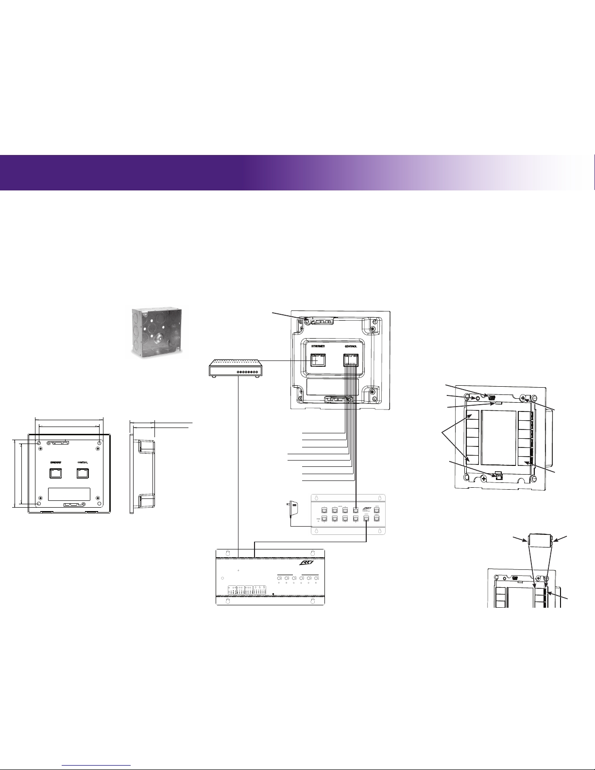
1) CB8 Connecting Block: Wire a Cat-5 cable from the KX2 Control Port to
the CB8 Connecting Block (see diagram).
2) Ethernet Port (Power over Ethernet): Wire a Cat-5 cable from the KX2
Ethernet Port to an 802.3af compliant Power-over-Ethernet router/switch
(Class #2).
NOTE: Using a non-compliant PoE device may damage the KX2.
3) Power Supply: Connect a power supply (+9VDC to +16VDC, .5A ) to the
“Ground” and “9-16VDC” pins of the Control Port (see diagram).
NOTE: The KX2 should NOT be powered from an RTI control
processor.
It’s Under Control
®
CONNECTIONS
CONTROL PORT
The Control Port on the KX2 uses a Cat-5 cable with RJ-45 termination. When
used in conjunction with an RTI control processor (e.g. RTI XP-6) and an RTI
connecting block (e.g. RTI CB-8), this port serves as the power source for
the KX2 in addition to infrared and RS-485 communication (see diagram for
pinout).
ETHERNET PORT
The KX2 Ethernet Port is designed for connection to an Ethernet network (LAN)
via Cat-5 cabling with RJ-45 termination. Additionally, the KX2 can be optionally
powered using Power-Over-Ethernet, allowing the power to be extended to the
KX2 over the same Cat-5 cable that carries Ethernet communication. When
powering the KX2 using PoE, a 802.3af compliant Power-over-Ethernet router/
switch (Class #2) must be used or damage to the unit may occur.
USB PORT
The KX2 USB port (located on the front of the unit beneath the bezel) is used to
update rmware and the programming data le using a USB-A to Mini-B cable.
POWERING THE KX2
The KX2 has many settings that can be adjusted directly through the control
panel. Please note that changes made directly in the KX2 control panel will be
overwritten by changes made in Integration Designer.
ACCESSING THE CONTROL PANEL
The Control Panel page can be displayed by pressing and holding down the
button located in the lower right corner of the KX2 (default labelled with the
power symbol), while applying power or resetting the KX2.
ADJUSTABLE SETTINGS
• Backlight Level • Time Out • Sound • Proximity Sensor
• Network Information
KX2
In-Wall Controller
MOUNTING
KX2 (Rear)
RESET
ETHERNET
EXPANSION
PORT 1 PORT 2 PORT 3
PORT 4
PORT 5
PORT 6
+
+ +
+ +
+
USB
RTI COM
POWER
STATUS
RS-232
POWER / IR
+12VDC TRIGGER
+3-24VDC SENSE
RELAYS (+30VDC, 5A MAX)
IR OUTPUT LEVEL
1
2
ModelXP-6
Advanced Control Processor
CB-8 Connecting Block
XP-6 Control Processor
Pin 8
Pin 7
Pin 6
Pin 5
Pin 4
Pin 3
Pin 2
Pin 1
Ground
Ground
Infrared
+9 to +16 VDC
+9 to +16 VDC
Infrared
RS-485-
RS-485+
Control Port
(Cat-5 Cable/
RJ-45 Jack)
Ethernet Port
(Cat-5 Cable/
RJ-45 Jack)
Ethernet
Router/Switch
(PoE Class#2)
Electrical Junction Box
4”h x 4”w x 1.5”d
D
12345678
1.2” (30.5mm)
1.3” (33mm)
4.4” (112mm)
4.6” (117mm)
PROGRAMMING
CONTROL PANEL
THE TOUCHSCREEN DISPLAY
The KX2 touchscreen display is programmed using the RTI Integration Designer
Programming Software. Normally it is organized into a series of pages containing
objects (buttons, text, graphics, etc.) that are related to each other. For
example, they may all display information necessary for controlling a particular
music server, room lighting, security system status etc.
UPDATING FIRMWARE
It is highly recommended that this and all RTI products have the latest rmware
installed. The rmware can be found in the Dealer section of the RTI website
(www.rticorp.com). Install the rmware using a USB cable (USB A to Mini B).
UPDATING SOFTWARE
RTI’s Integration Designer data les can be downloaded to the KX2 using a
USB cable (USB A to Mini B), or via the Ethernet network (LAN). If the KX2 is
hard-wired to a LAN and the router has DHCP enabled, the initial data le can be
downloaded over Ethernet.
Mounting Wings (2)
(One located on bottom
of KX2 also.)
KX2 (Front)
USB Port
Proximity and Ambient
Light Sensor
Programmable
Hard Buttons (12)
Touchscreen
“Power” Button
(Press to access
Control Panel-
see instructions)
Proximity Emitter
Reset Button
Mounting Wing
Screws (2)
HARD BUTTON REPLACEMENT
Button
Alignment
Tab
Button
Removal
Tabs
(Outer Edge)
KX2
Button
Pry up
here to
remove.
KX2 (Front)
KX2 DIMENSIONS
DOCUMENT NO.
B
C
D
12345678
0.534 (2)
0.648 (2)
3.4” (86mm)
3.789” (96.5mm)
1.2” (30.5mm)
2.354
0.712
1.3” (33mm)
3.4” (86mm)
3.789” (96.5mm)
4.4” (112mm)
4.6” (117mm)
KX2 (Rear)
(Cutout & Mounting Hole Dimensions)
KX2 (Side view)
 Loading...