

Page 1
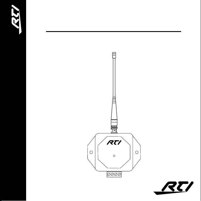
RM-433
Radio Frequency Receiver Module
IR-PRO
Professional Infrared Code Capture System
RM-433
Operation & Installation Guide
v1.0
RM-433
Receiver Module
DATA
+12VDC
GND
SIGNAL
N/C
Page 2

Introduction
The RM-433 is a radio frequency receiving device that operates at
433MhZ. It is designed to receive signals that are transmitted by
RTI universal system controllers.
The RM-433 contains a microprocessor that monitors all received
signals so that RF noise and data from non-RTI transmitters is
filtered out. When valid RTI data is detected, the RM-433 passes the
signal through its output driver which allows the data to travel long
distances over wire. The output driver is compatible with industry
standard infrared repeating systems, and can be wired together with
those systems or with additional RM-433 units. This allows RTI
control systems to be controlled from almost any location with
either IR or RF transmitters.
The RM-433 does not directly control A/V components - it is for
communicating to RTI control systems only.
Before using the RM-433, please read and follow all of the
instructions in this guide.
1
Page 3

Product Contents
Contents of the RM-433 sales kit include the following items:
! One (1) RM-433 radio frequency receiver module.
! One (1) flexible 1/2-wave whip antenna.
! One (1) 10 ft. (3m) hook-up wire.
! One (1) operation manual.
Features and Benefits
The RM-433 utilizes an innovative design concept that makes it an
ideal solution for professionally installed RTI control systems:
! Reliable RF reception due to matched antenna, connector,
and PCB.
! Modular design that allows multiple RM-433 units to be
wired together. This allows for any desired coverage area.
! Output signal is compatible with industry standard infrared
repeating systems. This allows multiple IR and/or RF
receivers to be wired together into an RTI control system.
! No dedicated power supply required. Power is derived
directly from the RTI control system.
! A feedback LED confirms operation.
! Available only to professional system integrators.
2
Page 4

Operation
The RM-433 is designed to operate with an RTI universal system
controller and central control system. It receives RF data that was
transmitted by the universal system controller, converts it to an
electrical signal, and transfers it to the central control system using
3-conductor wire. Power is derived from the control system, and no
programming or setup is required.
While power is applied to the RM-433 it will constantly monitor the
air for signals modulated at 433MhZ. The Data feedback LED
indicates the presence of these signals:
DATA LED
Off = No 433MhZ signal detected
Red = Noise or invalid data detected
Green = Valid data detected
Whenever the Data LED is green the RM-433 is sending the
received data through its output driver. If the Data LED is off or red,
the output driver is shut off. This prevents noise that is being
received by one RM-433 from interfering with valid data that is
being output by another RM-433 (if they are wired together to the
same control system).
3
Page 5

Connector Reference
RM-433
Receiver Module
DATA
+12VDC
GND
SIGNAL
N/C
+12VDC: Positive power supply connection. Connect to
+12VDC on RTI control system.
GND: Common ground connection. Connect to
GROUND on RTI control system.
SIGNAL: Data output connection. Connect to SIGNAL
IN on RTI control system.
N/C: No Connect. Do not connect this terminal.
Use 22
AWG
wire or larger. If Category 5 wire is used,
maintain pairs for each connection.
4
Page 6

Installation
The RM-433 can be mounted on a shelf, wall, or cabinet. See below
for recommended positioning. For the best reception connect two or
more RM-433 units together. This will help eliminate RF reception
drop-out due to multi-path interference. Up to ten RM-433 units can
be connected together as long as the total wire length does not
exceed 1000 ft. (300m).
5 ft. - 50 ft. (1.5m - 15m)
RM-433
Receiver Module
DATA
+12VDC
GND
SIGNAL
N/C
4 ft. (1.2m)
Minimum
3 ft. (1m)
Minimum
3 ft. (1m)
Minimum
RM-433
Receiver Module
DATA
+12VDC
GND
SIGNAL
N/C
5
Page 7

Mounting Hole Pattern
6
RM-433
Receiver Module
DATA
+12VDC
GND
3.0 in. (76mm)
SIGNAL
N/C
Page 8

Troubleshooting
If you are having problems with your RM-433 please read these
troubleshooting tips before contacting technical support.
The Data LED is constantly flashing red
• This does not necessarily indicate a problem that will effect
performance. If it does, move the RM-433 to a different area.
The Data LED never turns green
• Make sure the RM-433 is wired correctly to the central control
system, and verify the control system is powered-up.
• Make sure the RTI universal system controller is programmed
to output RF data.
The Data LED turns green when it receives a command, but the
control system does not respond
• Make sure the Signal terminal on the RM-433 is wired to the
Signal In terminal on the central control system. The Signal In
LED on the control system should illuminate.
• If there is also an infrared repeater connected to the control
system, make sure it is not injecting noise onto the signal line.
• Make sure the programming in the central control system
matches the universal system controller.
7
Page 9

Specifications
Power Requirements: +9VDC to +16VDC @ 60mA
RF Carrier Frequency: 433.92 MhZ
Output Drive: 200mA maximum
Operating Temperature: +32°F to +122°F
(+0°C to +50°C)
Operating Humidity: 5% to 95% non-condensing
Module Dimensions: 3.5 in. x 3.4 in. x 1.0 in.
(89mm x 86mm x 25mm)
Antenna Length: 13 in. (330mm)
Weight: 4.4 oz. (125 grams)
All specifications are subject to change.
8
Page 10

It's Under Control
Remote Technologies Incorporated
Remote Technologies Incorporated
Remote Technologies IncorporatedRemote Technologies Incorporated
18681 Lake Drive East
Chanhassen, MN 55317
Tel: 952-253-3100
Fax: 952-253-3131
www.rticorp.com
®
©
2004 Remote Technologies Inc. All rights reserved. Printed in USA.
 Loading...