

Page 1

Reference Manual - English - Version 4.3A
&
Barracuda
QABrowser
RTI article number: 9620501-00
Page 2

Welcome to Barracuda
and the QABrowser
The Barracuda is an X-ray Analyser/Multimeter for
everybody working with Quality Assurance and
Service of X-ray systems.
Page 3

NOTICE
Palm, palmOne, and TUNGSTEN are trademarks of PalmOne, Inc.
HotSync and Graffiti are trademarks of ACCESS CO., LTD
Microsoft, Windows, Win32, Windows XP, 2003, Vista, and 7 are either registered trademarks or
trademarks of Microsoft Corporation in the United States and/or other countries.
BLUETOOTH is a trademark owned by Bluetooth SIG, Inc., USA.
Notice
RTI Electronics Inc.
33 Jacksonville Road, Bldg. 1,
Towaco, NJ 07082,
USA
Phone: 800-222-7537 (Toll free)
Int. +1-973-439-0242
Fax: Int. +1-973-439-0248
E-mail
Sales: sales@rtielectronics.com
Support: support@rtielectronics.com
Service: service@rtielectronics.com
Web site: http://www.rti.se
Contact Information United States
RTI Electronics AB reserves all rights to make changes in the Barracuda, the
QABrowser, and the information in this document without prior notice.
RTI Electronics AB assumes no responsibility for any errors or consequential
damages that may result from the use or misinterpretation of any information
contained in this document.
Copyright © 2001-2012 by RTI Electronics AB. All rights reserved.
Content of this document may not be reproduced for any other purpose than
supporting the use of the product without prior permission from RTI Electronics
AB.
RTI Electronics AB
Flöjelbergsgatan 8 C
SE-431 37 MÖLNDAL
Sweden
Phone: Int. +46 31 7463600
Fax: Int. +46 31 270573
E-mail
Sales: sales@rti.se
Support: support@rti.se
Service: service@rti.se
Web site: http://www.rti.se
Contact Information World-Wide
Barracuda & QABrowser Reference Manual
2012-10/4.3A
III
Page 4

Intended Use of the Barracuda System
Accessory to diagnostic X-ray equipment to be used as an electrometer. Together with external
probes it is to be used for independent service and quality control, as well as measurements of
kerma, kerma rate, kVp, tube current, exposure time, luminance, and illuminance within
limitations stated below.
If installed according to accompanying documents, the product is intended to be used together
with all diagnostic X-ray equipment except for:
- therapeutical X-ray sources.
- X-ray equipment with tube potential below 20 kV.
- X-ray equipment on which the instrument cannot be mounted properly, e.g. equipment where
the beam field size is narrower than the active part of the detector.
- specific types of X-ray equipment listed in the instructions for use or in additional information
from the manufacturer.
With the X-ray installation in stand-by conditions without patients present, the product is intended
to be used:
- to provide the operator with information on radiation beam parameters that might influence
further steps in an examination but not an ongoing exposure.
- for assessing the performance of the X-ray equipment.
- for evaluation of examination techniques and procedures.
- for service and maintenance measurements.
- for quality control measurements.
- for educational purposes, authority supervision etc.
The product is intended to be used by hospital physicists, X-ray engineers, manufacturer's service
teams, and other professionals with similar tasks and competencies. The operator needs a short
training to be able to use the product as intended. This training can be achieved either by careful
study of the manual, studies of the built-in help function in measurement software or, on request,
in a short course ordered from the manufacturer.
The product is intended to be used inside X-ray rooms ready for clinical use and can safely be left
switched on and in any measuring mode in the vicinity of patients.
The product is NOT intended to be used:
- for direct control of diagnostic X-ray equipment performance during irradiation of a patient.
- so that patients or other unqualified persons can change settings of operating parameters during
and immediately before and after measurements.
Barracuda & QABrowser Reference Manual
2012-10/4.3A
Intended Use
IV
Page 5

Barracuda & QABrowser Reference Manual
2012-10/4.3A
Contents
1
Table of Contents
1.
........................................................................................................... 6
Introduction
..................................................................................................... 61.1 About this Manual
..................................................................................................... 61.2 Introduction to the Barracuda
..................................................................................................... 81.3 PC Requirements
..................................................................................................... 81.4 Palm OS Computer Requirements
2.
........................................................................................................... 10
Description of the Barracuda
..................................................................................................... 102.1 Overview of the Barracuda
..................................................................................................... 112.2 Cabinet and Modules
..................................................................................................... 142.3 The Multi-Purpose Detector (MPD)
..................................................................................................... 152.4 Setting Up the Barracuda for the First Time
..................................................................................................... 162.5 Setting Up the Barracuda
..................................................................................................... 172.6 Hardware and Specifications
.............................................................................................................172.6.1 Cabinet
..........................................................................................................172.6.1.1 General
..........................................................................................................182.6.1.2 Specifications, Cabinet
.............................................................................................................182.6.2 Multi-Purpose Detector (MPD)
..........................................................................................................182.6.2.1 General
..........................................................................................................192.6.2.2 Specifications, MPD
..........................................................................................................242.6.2.3 Typical Response, MPD
..........................................................................................................272.6.2.4 Angular Sensitivity, MPD
.............................................................................................................292.6.3 Signal-Extension Module (MP-SEM)
..........................................................................................................292.6.3.1 General
..........................................................................................................292.6.3.2 Specifications, MP-SEM
.............................................................................................................292.6.4 Electrometer Module (EMM)
..........................................................................................................292.6.4.1 General
..........................................................................................................302.6.4.2 Specifications, EMM
..........................................................................................................332.6.4.3 Optional Detectors
..........................................................................................................382.6.4.4 Typical Other Detectors
..................................................................................................... 412.7 Standards and Compliances
.............................................................................................................412.7.1 Waste Electrical and Electronic Equipment (WEEE)
.............................................................................................................422.7.2 Manufacturer's Declaration of Conformity
.............................................................................................................432.7.3 Intended Use
..................................................................................................... 442.8 Maintenance
.............................................................................................................442.8.1 Barracuda Batteries
..........................................................................................................442.8.1.1 Exchanging Batteries
..........................................................................................................442.8.1.2 Charging the Batteries
.............................................................................................................452.8.2 Updating the Barracuda Firmware
.............................................................................................................482.8.3 Managing Detector Calibrations
.............................................................................................................492.8.4 Transferring Detector Calibrations
.............................................................................................................502.8.5 Exchanging Modules
3. ........................................................................................................... 55Description of the QABrowser
..................................................................................................... 553.1 Introduction to the QABrowser
Page 6

Barracuda & QABrowser Reference Manual
2012-10/4.3A
Contents
2
..................................................................................................... 553.2 Starting the QABrowser
..................................................................................................... 563.3 Real-time Display and Waveforms
.............................................................................................................563.3.1 Using the Real-Time Display
.............................................................................................................613.3.2 Waveforms - Acquiring and Viewing
.............................................................................................................623.3.3 Measurement Settings
..........................................................................................................643.3.3.1 Settings - Conditions
..........................................................................................................683.3.3.2 Settings - Barracuda
..........................................................................................................703.3.3.3 Settings - MPD
..........................................................................................................723.3.3.4 Settings - Other Detectors
..................................................................................................... 723.4 QABrowser Applications
.............................................................................................................733.4.1 The Accuracy Application (single-parameter)
.............................................................................................................753.4.2 The Accuracy Application (multi-parameter)
..................................................................................................... 773.5 Data Logging
..................................................................................................... 793.6 Favourites
.............................................................................................................803.6.1 Getting Started with Favourites
.............................................................................................................833.6.2 Start here!
..................................................................................................... 833.7 QABrowser Setup
.............................................................................................................843.7.1 Regulations Setup
.............................................................................................................843.7.2 Units Setup
.............................................................................................................853.7.3 Log Setup
.............................................................................................................853.7.4 Preferences Setup
.............................................................................................................863.7.5 Detector Information
.............................................................................................................863.7.6 System Info
.............................................................................................................873.7.7 System Test
..................................................................................................... 873.8 Battery & Power Status
..................................................................................................... 893.9 Indicators and Symbols
..................................................................................................... 913.10 Installation of Palm OS Handheld Computers
.............................................................................................................913.10.1 Updating QABrowser on the handheld
.............................................................................................................933.10.2 Uninstalling the QABrowser
4. ........................................................................................................... 95Measurement Principles & Theory
..................................................................................................... 954.1 Overview of Capability for Measurement Modes
..................................................................................................... 954.2 Measurement Type Settings
..................................................................................................... 964.3 Update Modes
.............................................................................................................974.3.1 Using Timed Update Mode
.............................................................................................................984.3.2 Using Free Run Update Mode
..................................................................................................... 994.4 Display Messages and Active Messages
.............................................................................................................994.4.1 Active Messages
.............................................................................................................1004.4.2 Display Messages
..................................................................................................... 1024.5 Waveforms and Triggers
..................................................................................................... 1034.6 Measurement Principle for the MPD
..................................................................................................... 1044.7 HVL & Total Filtration
..................................................................................................... 1054.8 Linearity
..................................................................................................... 1064.9 Reproducibility
5. ........................................................................................................... 109Measurements with the Barracuda System
..................................................................................................... 1095.1 Introduction
..................................................................................................... 1105.2 Very Low Dose Rate Measurements with EMM-BiasW
Page 7

Barracuda & QABrowser Reference Manual
2012-10/4.3A
Contents
3
..................................................................................................... 1115.3 Radiography
.............................................................................................................1135.3.1 kVp, Time, Dose, and Dose Rate
.............................................................................................................1165.3.2 Dose Measurements with R100 or Ion Chamber
.............................................................................................................1175.3.3 HVL Application
.............................................................................................................1185.3.4 Quick-HVL and Total Filtration
..................................................................................................... 1205.4 Cine/Pulsed Radiography
.............................................................................................................1215.4.1 kVp, Time, Dose, and Dose Rate
.............................................................................................................1215.4.2 Pulse Measurements with R100 or Ion Chamber
.............................................................................................................1225.4.3 HVL, Quick-HVL, and Total Filtration
..................................................................................................... 1225.5 Fluoroscopy and Pulsed Fluoroscopy
.............................................................................................................1235.5.1 Image Intensifier Input Dose Rate
.............................................................................................................1255.5.2 kVp and Dose Rate
.............................................................................................................1275.5.3 HVL, Total Filtration, and Quick-HVL
.............................................................................................................1295.5.4 Pulsed Fluoroscopy
..................................................................................................... 1325.6 Mammography
.............................................................................................................1325.6.1 General
.............................................................................................................1345.6.2 Setting Up the Barracuda for Mammography
.............................................................................................................1365.6.3 kVp, Time, and Dose Measurements with the MPD
.............................................................................................................1385.6.4 Dose Measurements with the R100 or Ion Chamber
.............................................................................................................1405.6.5 HVL Application
.............................................................................................................1415.6.6 Mammo Compensations and Corrections
..........................................................................................................1415.6.6.1 Corrections for the Compression Paddle
..........................................................................................................1425.6.6.2 Normalization
..........................................................................................................1435.6.6.3 Beam Correction Factor
..........................................................................................................1435.6.6.4 Corrections for Angular Sensitivity
.............................................................................................................1445.6.7 Average Glandular Dose, AGD (MGD)
.............................................................................................................1455.6.8 Mammographic Pre-pulses
.............................................................................................................1455.6.9 Scanning Beam Mammography
..................................................................................................... 1465.7 Dental and Panoramic Dental
.............................................................................................................1495.7.1 kVp, Time, Dose, and Dose Rate
.............................................................................................................1525.7.2 Waveforms
.............................................................................................................1525.7.3 Panoramic Systems
.............................................................................................................1555.7.4 HVL, Total Filtration, and Quick-HVL
..................................................................................................... 1555.8 CT
.............................................................................................................1565.8.1 CT kVp
.............................................................................................................1585.8.2 CT Dose and CT Dose Index (CTDI)
.............................................................................................................1635.8.3 CT Scan Time (Exposure Time)
.............................................................................................................1635.8.4 CT mAs
.............................................................................................................1635.8.5 Parameters for CT Scanner Models
.............................................................................................................1645.8.6 Definition of CTDI
.............................................................................................................1645.8.7 Quick-HVL and Total Filtration
..................................................................................................... 1655.9 Tube Current Probes
.............................................................................................................1665.9.1 MAS-1B, Invasive mAs Probe
.............................................................................................................1685.9.2 MAS-2B, Non-invasive mAs Probe
.............................................................................................................1715.9.3 MAS-3, Non-invasive mAs Probe
..................................................................................................... 1745.10 Light Measurement
.............................................................................................................1745.10.1 Luminance - Monitor/Viewbox (cd/m²)
.............................................................................................................1755.10.2 Illuminance - Ambient Light (lx)
6. ........................................................................................................... 178Optional Accessories
Page 8

Barracuda & QABrowser Reference Manual
2012-10/4.3A
Contents
4
..................................................................................................... 1786.1 Holder & HVL Stand
..................................................................................................... 1786.2 Barracuda MPD Panoramic Holder
..................................................................................................... 1806.3 USB Serial Port Adapter
..................................................................................................... 1826.4 Barracuda Bluetooth Serial Module
7. ........................................................................................................... 186Problems and Solutions
..................................................................................................... 1867.1 Troubleshooting
..................................................................................................... 1887.2 Bluetooth
.............................................................................................................1887.2.1 Bluetooth Passkey
.............................................................................................................1907.2.2 Enable Bluetooth Passkey
..................................................................................................... 1917.3 How To Report a Problem
8. ........................................................................................................... 193Glossary
........................................................................................................... 204Index
Page 9

Introduction
Chapter 1
Page 10

1. Introduction
About this Manual
Barracuda & QABrowser Reference Manual
2012-10/4.3A
6
1 Introduction
About this Manual1.1
This manual is divided into a few main parts.
1. A general description of the Barracuda.
2. A general description of the QABrowser.
3. Some theoretical background and basic principles.
4. Descriptions on performing measurements with the system for different
modalities.
5. Description of different accessories for the Barracuda.
6. Troubleshooting tips, an FAQ, and a glossary.
Users who use the Barracuda with only a PC and oRTIgo are recommended to read at
least the following topics:
· Introduction
· Description of the Barracuda
· Measurements with the Barracuda System
This manual gives a short introduction to handheld computers and enough of
information to get started and use it with the Barracuda. However, it is advised (if you
are going to use a handheld computer) to study the manual that is included with your
handheld computer to get familiar with its capabilities.
Pictures in included manuals for detectors and probes may include an ADI module (a
small module with a connector attached to the detector cable). ADI modules are used
to store calibration data and used by other products than the Barracuda from RTI
Electronics. For the Barracudasystem, calibration data is instead stored inside the
system. See section Managing Detector Calibrations for more information.
The handheld computer is sometimes called "Palm" or "Palm computer" in this manual,
this is referring to all types of handheld computers running Palm OS or Windows
Mobile that currently are possible to use with the Barracuda and the QABrowser.
Typographical Rules
Terms in bold face are references to texts on screenshots, like buttons and texts, and
menu items. Other terms are italicized.
Introduction to the Barracuda1.2
Congratulations to your purchase of a Barracuda. You have now in your hand the most
powerful tool for X-ray analysis. It has been carefully designed to meet the needs of
both standard QA applications as well as advanced service/repair/calibration of
modern X-ray systems, while still being very simple and intuitive to use. It can measure
all the required parameters such as kVp, exposure time, dose, dose/pulse, dose rate,
tube current, mAs, waveforms, and much more. One single detector, the unique
multi-purpose detector (MPD) can be used for radiography, mammography,
fluoroscopy, pulsed fluoroscopy, cine, dental, dental panoramic, and CT (not CT dose).
48
Page 11
1. Introduction
Introduction to the Barracuda
2012-10/4.3A
7
Barracuda & QABrowser Reference Manual
The Barracuda can be used in two different ways:
· As a "meter" with a handheld computer and the QABrowser.
· As a complete "QA-system" with a PC and the oRTIgo software.
This manual describes the Barracuda and the QABrowser. The PC software, oRTIgo,
is described in a separate manual.
The Barracuda system's main features are:
· Very easy and intuitive to use
· Accurate
· No manual corrections are needed
· Measures on all modalities with one detector
· Specially designed measuring modes for pulsed waveforms
· Compact
· QABrowser or oRTIgo is used for control and data processing
· Waveform analyser with high-speed sampling and long storage time
· The modular design guarantee easy upgrade and enhanced serviceability
· RS-232 and USB interface
· Free upgrade of firmware (software in cabinet and modules)
· New and unique design
The modular design makes it very simple to upgrade your Barracuda hardware if you
later need more measuring capacity or when new technology requires new measuring
capabilities. RTI Electronics will continuously add new functions and make
improvements to the Barracuda. Free upgrades of the firmware (the software resident
in the cabinet and measuring modules) are available on RTI Electronics Web site at
http://www.rti.se.
If you have questions, comments, or feel that some functionality is missing, you are
welcome to contact us at RTI Electronics at sales@rti.se. You can of course also call
or send a fax (see notice section for details).
Page 12

1. Introduction
PC Requirements
Barracuda & QABrowser Reference Manual
2012-10/4.3A
8
PC Requirements1.3
To run the RTI Updater and the QABrowser Updater the following is required:
Minimum requirements
Windows XP, 2003, Vista, 7 32-bit, or 7 64-bit.
Pentium class 300 MHz, 64 MB RAM (24 MB free), 60 MB of HD
1
USB port or RS232 serial port
Display and graphics card with at least 800×600 resolution
Recommended requirements
Windows 7 32-bit
Pentium class 500 MHz, 128 MB RAM (32 MB free), 100 MB HD
USB port
CD/DVD-ROM for installation
Internet connection for updates (Recommended)
1: Virtual memory and available hard drive space. Microsoft recommends that you
have at least 20 % of your total HD space free for virtual memory.
Palm OS Computer Requirements1.4
To run the QABrowser the following is required:
Minimum requirements
· PalmOS v5.0 or higher
· 16 MB of memory
· Colour screen with a resolution of 320×320 pixels
· Palm connection:
Either cable with connector:
- Universal (Tungsten T, T2, T3)
- Multi (Tungsten E2, Tungsten T5, TX, Treo 650, ...)
Or Bluetooth wireless (with optional Bluetooth adapter for Barracuda).
Recommended requirements
· RTI Handheld Display or Palm Tungsten E2/TX
· Bluetooth wireless (with optional Bluetooth adapter for Barracuda).
Page 13

Description of the
Barracuda
Chapter 2
Page 14

2. Description of the Barracuda
Overview of the Barracuda
Barracuda & QABrowser Reference Manual
2012-10/4.3A
10
2 Description of the Barracuda
Overview of the Barracuda2.1
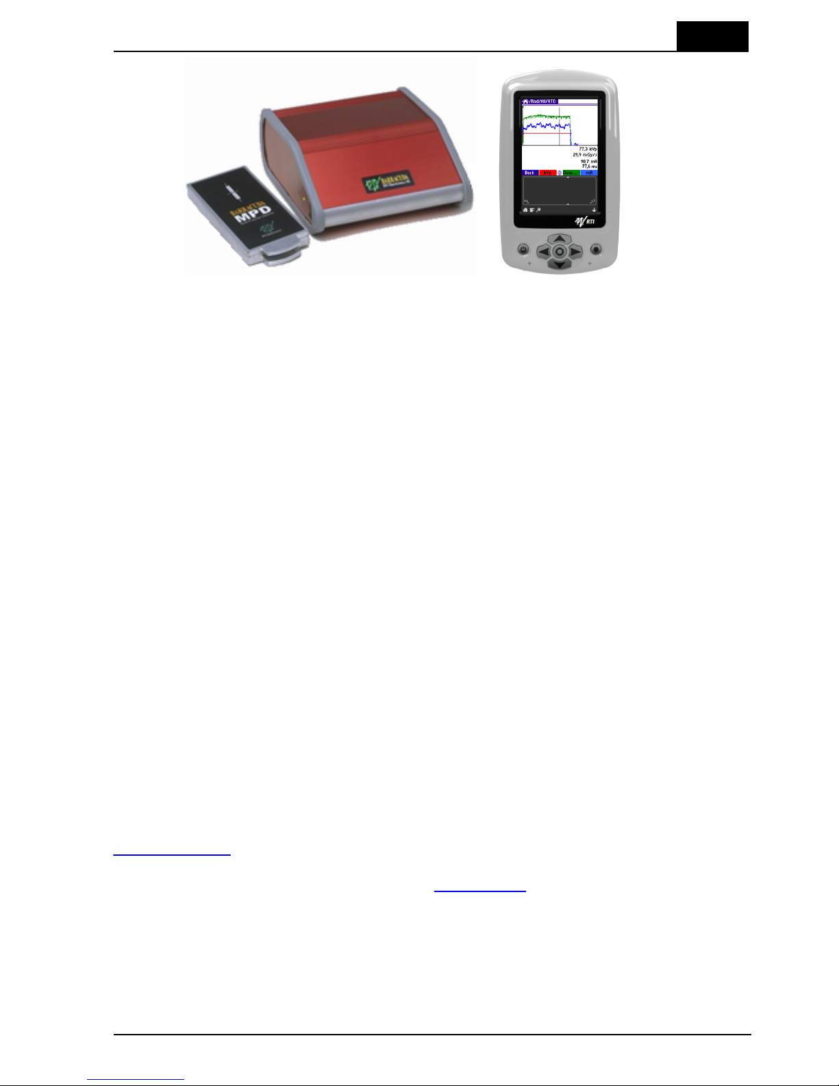
The main parts of a typical Barracuda system are:
· The cabinet, containing one or more modules
· The Multi-Purpose Detector, called MPD, measuring tube voltage, exposure time,
dose, and dose rate
· A handheld computer with the QABrowser software and/or a PC with the oRTIgo
software
Multi-Purpose Detector
(MPD)
Cabinet
(with modules)
Handheld computer
(RTI Handheld Display shown)
Many different probes and detectors can be used with the Barracuda. These probes
require at least one EMM (electrometer module):
· R100, solid-state dose detector for low dose rate measurements.
· R100B, solid-state dose detector for low or very low dose rate measurements.
· L100B, light detector for test of viewing boxes and monitor screens.
· MAS-1B, MAS-2B, or MAS-3, mAs probes for tube current and charge
measurements.
· DCT10 or DCT16, CT ionization chambers.
· Other ionization chambers with BNT, TNT, or BNC/Banana connectors.
Later in this manual the different probes and detectors are described.
Below a block diagram of a typical Barracuda system is shown.
Page 15

2. Description of the Barracuda
Overview of the Barracuda
2012-10/4.3A
11
Barracuda & QABrowser Reference Manual
Cabinet and Modules2.2
The cabinet is the main part of the Barracuda to which all detectors are connected. The
cabinet can be configured in different ways depending on the requirements of the user.
Connectors, switches, and indicators are located both on the cabinet and on the
contained modules. This section gives a brief description of the cabinet and the
modules. A more detailed description of each module is found in Hardware and
Specifications .
Charging of batteries
Indicates when the
internal batteries are
charging
External power supply
Indicates when the external
power supply is connected
Power switch
Turns the Barracuda on and
off
The Power switch is used to turn the Barracuda on and off. Barracuda has several
ways of saving power when it is inactive, but must be powered off manually since there
is no auto-power off function.
The indicator for Charging of batteries is lit when charging is enabled and chargeable
batteries are used. Only use recommended batteries and never charge
non-chargeable batteries. This may damage your Barracuda cabinet.
17
Page 16

2. Description of the Barracuda
Cabinet and Modules
Barracuda & QABrowser Reference Manual
2012-10/4.3A
12
The indicator for External power supply is lit when the Barracuda is powered from an
external power source. Use only the power supply that comes with the Barracuda.
Support for Palm Holder (for old Palm models)
Serial interface
Connects to a handheld
computer or PC
USB interface
Connects to a PC
Power supply input (12 V)
Use only approved power
supply
The Serial interface is an RS-232 interface and is used to connect to the handheld
computer or to a PC. Here a Bluetooth adapter, the RS232 PC interface (serial cable
between PC and Barracuda), or the Palm interface (serial cable between handheld and
Barracuda) may be connected. The data speed is 57,6 kbit/s when using a handheld
computer, and maximum 115 kbit/s when using a PC.
The USB interface is used to connect the Barracuda to a PC running the QA software
oRTIgo. Note that the USB connector cannot be used when connecting to a handheld
computer.
The external power supply (12 V) is connected to the Power connector. Use only the
power supply recommended by the manufacturer. Country-specific plugs are available.
On the rear of the cabinet all connectors for detectors and probes are found.
Page 17

2. Description of the Barracuda
Cabinet and Modules
2012-10/4.3A
13
Barracuda & QABrowser Reference Manual
EMM
Electrometer Module
MP-SEM
Signal Expansion Module for MPD.
Combined with MPM.
EMM LED
indicator
Indicates if the
module is selected
or active
EMM Input
Channel #2 (b)
EMM Input
Channel #1 (a)
MPM
Multi-Purpose
Module. Connects to
MPD.
MPM LED indicator
Indicates if the
module is selected or
active
MPM Connector
Connects to MPD via
the MPD Cable.
MP-SEM
MPD high-speed
electrometer input
Trig input
To MPD
Waveform out and Trig out
From MPD
The figure above shows a cabinet with three modules and three free slots ("dummy
modules"). The number and type of modules are depending on the configuration of
your Barracuda system.
An orange LED indicator is located on all modules. The LED indicator is used for
different purposes:
· Indicates that the module is selected.
· Used to guide the user to connect a probe or detector to the right module.
The function of the LED is described more in detail in the topic Hardware and
Specifications .
The following module types are presently available
MPM
Multi-Purpose Module. The Multi-Purpose Detector is connected to this
module via a 2 m cable (or an optional 6 m cable).
MP-SEM
This module is used for special measurements. The module has a
signal input that can be used to acquire any kind of external signal. The
module also has a Trig In and a Trig Out connector. This makes it
possible to start a measurement from an external signal rather than
from the measured signals. You can also supply a trig signal from the
Barracuda to other systems.
Five different types of EMM modules (electrometer modules) are available.
EMM-1Ch
One channel electrometer without bias voltage. This module is
necessary for all standard measurement with solid-state dose
detectors, light detector, and mAs probes.
EMM-2Ch
Two channel electrometer without bias voltage. It is the same as
17
Page 18

2. Description of the Barracuda
Cabinet and Modules
Barracuda & QABrowser Reference Manual
2012-10/4.3A
14
EMM-1Ch but it has two channels that can be used independent of
each other allowing you to measure with two external detectors
simultaneously.
EMM-Bias
One channel electrometer with built-in polarizing voltage supply (bias)
and floating input. This module is required when using ionization
chambers with LEMO connectors (BNT or TNT adapters are available).
The bias can be turned off, allowing use of solid-state dose detectors,
light detectors, and mAs probes. The bias voltage is user selectable
between –300 V and +300 V. A yellow LED is indicating when the bias
is activated. Note that turning on and off the polarizing voltage (bias)
takes approximately 15 seconds.
Warning: Always make sure that the bias is off before connecting
detectors.
EMM-BiasB
One channel electrometer with built-in polarizing voltage supply (bias).
It is the same as EMM-Bias but the bias voltage can be output either as
a floating input on the LEMO triaxial connector or on the 3 mm banana
connector.
This means that this module supports both ion chambers with triaxial
connectors (LEMO, BNT, or TNT connectors) as well as BNC/Banana
connectors.
EMM-BiasW
One channel electrometer with built-in polarizing voltage supply (bias).
It is the same as EMM-BiasB but it can only be used with unipolar
positive current detectors, like R100B, MAS-2B, and ion chambers.
This module supports both ion chambers with triaxial connectors
(LEMO, BNT, or TNT connectors) as well as BNC/Banana connectors.
Modules can easily be uninstalled or installed by the user at any time allowing easy
upgrade or solve technical problems without sending away the complete Barracuda
system for service. Read more in the topic Exchange of modules .
The Multi-Purpose Detector (MPD)2.3
The Multi-Purpose detector is a universal detector used for all type of X-ray systems;
radiography, cine, fluoroscopy, pulsed fluoroscopy, mammography, dental, panoramic
dental, and CT. You can measure the following parameters in one exposure with the
MPD:
· Tube voltage (kVp)
· Exposure time
· Dose (CT dose requires a special CT ionization chamber)
· Dose rate
· Dose/pulse and pulse rate
· Total filtration (radiography, fluoroscopy, dental, and CT, 50 - 150 kV, 1.5 mm to
38 mm Al)
· Quick-HVL (radiography, fluoroscopy, dental, and CT, 50 - 150 kV, 1.2 mm to
14 mm Al)
· kVp waveform
· Dose rate waveform
The estimations of total filtration and Quick-HVL are done from one single exposure
using a combination of detector and filters in the MPD. In situations when the total
50
Page 19

2. Description of the Barracuda
The Multi-Purpose Detector (MPD)
2012-10/4.3A
15
Barracuda & QABrowser Reference Manual
filtration cannot be automatically estimated, a "standard" HVL measurement may be
required. All measured kVp and dose values measured with the MPD are automatically
compensated for the actual beam quality. This means that no manual corrections of
measured data is needed.
Range indicator
(on the edge as
shown below)
Detector area
The white marking
indicates where the active
detector area is located.
Minimum X-ray field is
3×21 mm.
Range indicator (3 in this case)
The MPD utilizes a completely new technology using several detectors and filters to
measure. No manual filter changes are required since the filters are located inside the
MPD and moved by commands from the handheld computer or the PC. A range
indicator is visible on the edge at the top of the MPD. A number corresponding to each
filter is shown, and this number is also used in the QABrowser and oRTIgo to identify
different ranges. This indicator can be used to verify the mechanical function of the
MPD.
The active detector area is marked by a white rectangle on the top panel of the MPD.
The minimum X-ray field that can be used is 3×21 mm. The actual width of the detector
is 2.7 mm. The detector surface is 8 mm below the surface, as indicated by the lower
edge of the range indicator opening. The MPD has a special Check function to verify
the position of the MPD and compensate for small mis-alignments or inhomogenities.
The MPD is very sensitive and can measure at very low output from the X-ray tube.
The MPD connects to the MPM in the cabinet via a 2 m cable (an optional 6 m cable is
available). The normal way to work with the Barracuda is to place the cabinet and the
MPD close to the tube inside the X-ray room. The handheld computer or PC is
connected with a long cable and placed in the control room together with the user.
Setting Up the Barracuda for the First Time2.4
Before you use your Barracuda for the first time, please do the following:
· Mount the batteries.
· Attach the external power supply.
Page 20

2. Description of the Barracuda
Setting Up the Barracuda for the First Time
Barracuda & QABrowser Reference Manual
2012-10/4.3A
16
· Charge the system for 16 hours.
Then continue according to the following section.
Setting Up the Barracuda2.5
The Barracuda system comes in a customized case. Two different cases are available,
one smaller carrying case (CAS-6) with space for a basic Barracuda system.
The larger case (CAS-7) is a transportation case
with space for a complete Barracuda system
with all its accessories. The cases are designed
to store typical accessories to the Barracuda,
like Palmtop, probes, chargers, and cables.
The figure above shows the smaller case, the CAS-6.
To set up the Barracuda:
1.
Pick up the cabinet, the MPD, and the handheld computer from the case.
2.
Connect the MPD cable to the connector on the rear on the cabinet, see figure
below. The connector has the text "TOP" on one side. This text should be pointing
up when connecting the MPD cable. If there is no text use the two marks on one
side. These marks should be to the right when you are looking at the cabinet from
the rear. Do not use unnecessary force. To disconnect the MPD cable press the two
"buttons" on each side of the connector house and gently remove it.
MPD Cable with connector
3.
Connect the other connector to the MPD. The connector has the text "TOP" on one
side. The text should be at the same side as the MPD detector area. If there is no
text let the marks (from 2 above) be on the side towards the bottom of the MPD. Do
Page 21

2. Description of the Barracuda
Setting Up the Barracuda
2012-10/4.3A
17
Barracuda & QABrowser Reference Manual
not use unnecessary force. To disconnect the MPD cable press the two "buttons" on
each side of the connector house and gently remove it.
4. Place the MPD under the tube or mount the holder and HVL
stand for positioning of the MPD in the X-ray field. See the
figure to the left. The stand allows you to position the MPD (or
the R100 dose detector) and HVL filters in any angle including
upside-down. Use the light-field or other help to position the
MPD in the X-ray field. The MPD detector is not sensitive for
different field sizes as long as the entire sensitive detector
area is irradiated, but try to keep the field size down to
minimize scattering.
It is also recommended to position the MPD in such a
way that the detector area is orientated perpendicular to the
anode/cathode axis, to avoid the heel effect.
Recommended field size is 20×40 mm.
5. Optionally you may connect the power supply to the cabinet.
Now everything is set up with the hardware.
Hardware and Specifications2.6
Specifications are valid after a warm-up time of one minute and presuming reference
conditions. All specifications are for use together with the Barracuda unless otherwise
stated. All specifications can be changed without prior notice. RTI Electronics AB
assumes no responsibility for any errors or consequential damages that may result
from the misuse or misinterpretation of any information contained in these
specifications.
2.6.1 Cabinet
2.6.1.1 General
The cabinet is the hub of the Barracuda system. The cabinet holds the different
modules and controls their functionality. The cabinet also controls the data flow
between the modules and the user interface, which can be either a handheld computer
or a PC.
The cabinet has six places for modules, there are several different electrometer
modules, one signal extension module, and a multi-purpose module (that connects to
the multi-purpose detector) available. The modular design gives a flexible system,
which can be individually designed to fit almost any QA need. The Barracuda uses six
1.5 V R6 batteries (alkaline or chargeable) or an external 12 V DC power supply. The
chargeable batteries can be recharged when the Barracuda is powered from the
external power supply. The operation time depends on the number of modules used,
and mode of operation. See the table below for approximate operation times (with
Cabinet firmware v1.4A or newer).
There are two ways to control the Barracuda and to present measured data; either via
a handheld computer or through a PC. The cabinet has two different interfaces, RS232
and USB.
Page 22

2. Description of the Barracuda
Hardware and Specifications
Barracuda & QABrowser Reference Manual
2012-10/4.3A
18
2.6.1.2 Specifications, Cabinet
General
Size
155 × 135 × 62 mm, (6.1" × 5.3" × 2.4")
Weight
Approximately 1,0 kg
Operating temperature and
relative humidity
15 – 35 °C
at <80 % relative humidity
Storage temperature
–10 °C to +50 °C
Operating air pressure
Minimum 80 – 106 kPa
Power Source
Power supply
12 V AC/DC adapter
Battery operated
Six 1.5 V batteries type LR6 (size AA), alkaline or type HR6
chargeable NiMH. Operation time (with 1 EMM and 1 MPD),
typically:
· 5 hours with 2100 mAh NiMH batteries
· 6.5 hours with 2600 mAh NiMH batteries
· 3-4 hours with alkaline batteries.
External power
100-240 V AC 50/60 Hz with external adapter. Chargeable
batteries can be charged in the cabinet when external power is
connected.
When not running the MPD motor, the system may also be
supplied from a laptop computer via USB. The USB supply
current is limited, so it may not work in all cases.
PC Communication
USB
Max 12 Mbit/s (USB v1.1)
RS232 / Bluetooth
19.2 – 115 kbit/s
Handheld Computer Communication
RS232 / Bluetooth
19.2 – 57.6 kbit/s
2.6.2 Multi-Purpose Detector (MPD)
2.6.2.1 General
With this multi-purpose detector you will manage most of your measurements. Tube
voltage, exposure time, dose, and dose rate are measured for all kinds of modalities:
conventional radiography, fluoroscopy, pulsed fluoroscopy, cine, mammography,
dental, panoramic dental, and CT (kVp only, not dose and doserate). In one exposure,
the detector provides tube voltage, time, dose, dose rate, quick-HVL, and estimated
total filtration on radiographic, fluoroscopic, dental, and CT exposures. On pulsed
radiation and cine, also dose per pulse and pulse rate are measured. The
multi-purpose detector is very sensitive and can measure peak tube voltage for as low
outputs as 50 kV / 0.050 mA at 50 cm.
Page 23

2. Description of the Barracuda
Hardware and Specifications
2012-10/4.3A
19
Barracuda & QABrowser Reference Manual
Typically the exposure time has to be at least 5 ms to get a kVp value but it depends
on the waveform. On modern X-ray generators (high-frequency with fast rise and fall
times) the peak tube voltage can normally be measured with exposure time as short as
1 ms. Dose and time values will be given for even shorter exposure times.
The multi-purpose detector is connected to the multi-purpose module with a 2 m cable
(an optional 6 m cable is also available), however all specifications given are for the
2 m cable.
2.6.2.2 Specifications, MPD
The inaccuracy is here defined as the root of the square sum of systematic errors,
which has not been eliminated, and random errors (dispersion around a mean value).
The calculation of the inaccuracy is based on 15 different measurements and with a
confidence level of 95 %. Of the total inaccuracy, random error is 20 % and general
inaccuracy is 80 %.
Note: Irradiation time is often called exposure time in daily use.
Reference conditions
Temperature
+18 °C to +23 °C
Relative humidity
50 %
Air pressure
101.3 kPa
X-ray field size
Inside the MPD top panel.
Calibration is done with field size typically 5 mm less than the size of the
top panel.
Radiation quality
Radiography
Mammography
CT
70 kV, 2.5 mm Al
28 kV, 30 µm Mo
120 kV, 2.5 mm Al
Note: The reference conditions are given in reference to the IEC61674 standard.
Physical dimensions
Detector area
3 × 21.1 mm
Detector position
8.13 mm below top panel, as indicated in figure below.
Size
122 × 55 × 14 mm (4.8" × 2.1" × 0.55")
Weight
Approximately 250 g
Page 24

2. Description of the Barracuda
Hardware and Specifications
Barracuda & QABrowser Reference Manual
2012-10/4.3A
20
Parameters
Tube voltage (kVp)
The average of all samples with compensation for the ripple
(default method)
Time
Irradiation time (Exposure time)
Air kerma (Dose)
Measured air kerma (may be called dose or air kerma in this
manual)
Air kerma rate (Dose rate)
Average air kerma rate (may be called dose rate or air kerma rate
in this manual)
Total Filtration
Estimation of total filtration (for conventional radiography,
fluoroscopy, dental, and CT)
Quick-HVL
Estimation of Half Value Layer (for conventional radiography,
fluoroscopy, dental, and CT)
Half Value Layer
Standard HVL using filters for evaluation on radiography,
fluoroscopy, dental, and mammography (all for both pulsed and
conventional)
kV waveform
Waveform is calculated based on detector signals measured after
different thickness of filtration.
Dose rate waveform
Signal measured from radiation detector (ionization chamber or
solid-state detector).
Page 25

2. Description of the Barracuda
Hardware and Specifications
2012-10/4.3A
21
Barracuda & QABrowser Reference Manual
Measuring range and inaccuracy
Radiography, Fluoroscopy, and Dental
ParameterBQRange
Inaccuracy
Resolution
kVp (standard)
W / 3 mm Al
R1
35 – 155 kV
±1.5 %
4 digits
(10 or 100 V)
kVp dental
W / 3 mm Al
R1
35 – 105 kV
±1.5 %
As above
Irradiation time
0.1 ms – 2000 s
1 – 65535 pulses
±1 % or ±0.5 ms
±1 pulse
0.5 ms
1 pulse
Air kerma (Dose)
2
15 nGy – 1000 Gy
(2 µR – 100 kR)
±5 %
–
Air kerma rate
2
(Dose rate)
-Overall
15 nGy/s – 450 mGy/s
3
1.7 µR/s – 50 R/s
0.1 mR/min – 3000
R/min
±5 % or ±7 nGy/s
±5 % or ±0.8 µR/s
±5 % or ±0.05
mR/min
(for Irr. time >20 ms)
Typ. noise:
3 nGy/s
-Free run
-High Sensitivity
-Low Sensitivity
15 nGy/s – 12 mGy/s
2
150 nGy/s – 12 mGy/s
2
25 µGy/s – 450 mGy/s
2
±5 % or ±7 nGy/s
±5 % or ±7 nGy/s
±5 % or ±0.1 µGy/s
Typ. noise:
3 nGy/s
Estimated total
filtration
1.5 – 38 mm Al
(50 – 150 kV)
±10 % or ±0.3 mm
(60 – 120 kV,
HF/DC)
2 digits
(0.1 or 1 mm)
Quick-HVL
1.2 – 14 mm Al
4
(50 – 150 kV)
±10 % or ±0.2 mm
(60 – 120 kV,
HF/DC)
1
3 digits
(0.01 or 0.1 mm)
Note 1: This is valid for a tube with 13° anode angle. The HVL for a 22° anode is typically 0,5 mm
lower (@ 80 kV, 3 mm TF).
Note 2: All kerma and kerma rate ranges, inaccuracy, and resolution figures are valid for product
version 2 and higher of the MPD.
Note 3: The Kerma rate is calculated as the Kerma (Dose) divided by the Irradiation time. See
also Waveforms and Triggers .
Note 4: The HVL range is valid if also the TF is within its specified range. For high TF at high kV
the HVL range may be limited by this.
102
Page 26

2. Description of the Barracuda
Hardware and Specifications
Barracuda & QABrowser Reference Manual
2012-10/4.3A
22
Mammography
Parameter
BQ
Range
Inaccuracy
Resolution
kVp (standard)
Mo / 30 µm Mo
Mo / 25 µm Rh
Rh / 25 µm Rh
W / 50 µm Rh
W / 0.50 mm Al
Mo / 1.0 mm Al
W / 55 µm Ag
W / 75 µm Ag
W / 50 µm Rh (Gio)
M1
M3
M4
M6
M7
M8
M10
M11
M12
18 – 49 kV
22 – 44 kV
25 – 49 kV
22 – 46 kV
20 – 48 kV
18 – 49 kV
20 – 40 kV
20 – 40 kV
22 – 35 kV
±1.5 % or ±0.7 kV
±2 % or ±1 kV
±2 % or ±1 kV
±2 % or ±1 kV
±2 % or ±1 kV
±2 % or ±1 kV
±2 % or ±1 kV
±2 % or ±1 kV
±2 % or ±1 kV
4 digits
(10 V)
kVp (optional)
Mo / 30 µm Mo +
+ 2 mm Al
Mo / 2.0 mm Al
Rh / 1 mm Al
M1d
M2
M5
25 – 35 kV
18 – 49 kV
22 – 35 kV
±2 % or ±1 kV
±2 % or ±1 kV
±2 % or ±1 kV
4 digits
(10 V)
Irradiation time
0.1 ms – 2000 s
1 – 65535 pulses
±1 % or ±0.5 ms
±1 pulse
0.5 ms
1 pulse
Air kerma (Dose)
1
25 nGy – 1500 Gy
3 µR – 150 kR
±5 %
±5 %
–
Air kerma rate
1
(Dose rate)
-Overall
25 nGy/s – 750 mGy/s
2
30 µR/s – 86 R/s
1.8 mR/min –
5100 R/min
±5 % or ±12 nGy/s
±5 % or ±1.5 µR/s
±5 % or ±0.1 mR/min
(for Irr. time >20 ms)
Typ. noise:
6 nGy/s
-Free run
-High Sensitivity
-Low Sensitivity
25 nGy/s – 20 mGy/s
0.25 µGy/s – 20 mGy/s
45 µGy/s – 750 mGy/s
±5 % or ±12 nGy/s
±5 % or ±12 nGy/s
±5 % or ±0.2 µGy/s
Typ. noise:
6 nGy/s
Note 1: All kerma and kerma rate ranges, inaccuracy, and resolution figures are valid for product
version 2 and higher of the MPD.
Note 2: The Kerma rate is calculated as the Kerma (Dose) divided by the Irradiation time. See
also Waveforms and Triggers .
102
Page 27

2. Description of the Barracuda
Hardware and Specifications
2012-10/4.3A
23
Barracuda & QABrowser Reference Manual
Computed Tomography
Parameter
BQ
Range
Inaccuracy
Resolution
kVp (standard)
W / 3.0 mm Al
C1
45 – 155 kV
±1.5 %
4 digits
(10 or 100 V)
kVp (optional)
W / 3.0 mm Al +
0.25 mm Cu
W / 3 mm Al + 1.2 mm Ti
(Siemens Sensation 32) 2
GECT 2, 3
C2
C3 2
C4
80 – 150 kV
75 – 145 kV
75 – 145 kV
±1.5 %
±1.5 %
±1.5 %
4 digits
(10 or 100 V)
Irradiation time
0.1 ms – 2000 s
1 – 65535 pulses
±1 % or ±0.5 ms
±1 pulse
0.5 ms
1 pulse
Air kerma (Dose)
4 4 4
Estimated total
filtration
1.5 – 38 mm Al
(75 – 150 kV)
±10 % or ±0.3 mm
(75 – 120 kV, HF/DC)
2 digits
(0.1 or 1 mm)
Quick-HVL
1.2 – 14 mm Al
(75 – 150 kV)
±10 % or ±0.2 mm
(75 – 120 kV,
HF/DC)
1
3 digits
(0.01 or 0.1 mm)
Note 1: This is valid for a tube with 13° anode angle. The HVL for a 22° anode is typically 0,5 mm
lower (@ 80 kV, 3 mm TF).
Note 2: The C3 and C4 calibrations are only available for product versions 2.0 or higher.
Note 3: The C4 calibration may also be useful for new technology CTs, like Toshiba Aquilion 320
or Siemens Straton (when also HVL and TF is needed).
Note 4: CT dose is measured with a CT ionization chamber connected to an electrometer module.
See topic Specifications, EMM for details.
Pulses
Parameter
Range
Dose/pulse
8 nGy/pulse - 60 kGy/pulse
1
Pulse dose rate
Lower limit 10 µGy/s (70 mR/min) otherwise, same as
for air kerma rate.
Min. output peak dose rate
- High Sensitivity
- Low Sensitivity
dose rate (min. pulse width)
4 µGy/s (4 ms) / 30 µGy/s (0.5 ms)
20 µGy/s (4 ms) / 160 µGy/s (0.5 ms)
Pulse rate
0.5 – 180 Hz, resolution 0.5 Hz
Pulse width
4 ms - 2000 s
Duty cycle
5 - 95 %
Minimum pulse width
- High Sensitivity
- Low Sensitivity
pulse width (min. dose rate)
4 ms (4 µGy/s) / 0.5 ms (30 µGy/s)
4 ms (20 µGy/s) / 0.5 ms (160 µGy/s)
Minimum ripple
(pulse top to bottom)
50 %
Irradiation time
1 – 65535 pulses, resolution 1 pulse
Note 1: Max dose/pulse depends on the pulse length.
Note 2: All kerma and kerma rate ranges, inaccuracy, and resolution figures are valid for product
version 2 and higher of the MPD.
30
Page 28

2. Description of the Barracuda
Hardware and Specifications
Barracuda & QABrowser Reference Manual
2012-10/4.3A
24
2.6.2.3 Typical Response, MPD
The table below shows the typical response for the MPD at standardised radiation
qualities.
Radiography, Fluoroscopy, and Dental (measured using RTI RQ Code R1, W/Al)
Radiation quality
Mean energy
air kerma
(keV)
Total
Filtration
(mm Al)
Air kerma measurement
PTB
ISO 4037
IEC 61267
HVL
(mm Al)
Factor kQ
(Rel. RQR 5)
DV40
RQR 2
26,38
2,49
1,42
1,0186
DV50
RQR 3
29,14
2,46
1,77
0,9794
DV60
RQR 4
32,14
2,68
2,19
0,9949
DV70
RQR 5
34,84
2,83
2,571DV80
RQR 6
37,88
2,99
3,01
0,9976
DV90
RQR 7
41,1
3,18
3,48
0,9920
DV100
RQR 8
44,33
3,36
3,96
0,9920
DV120
RQR 9
50,86
3,73
5,00
0,9988
DV150
RQR 10
61,47
4,38
6,55
1,0199
Note: These values are typical values measured at PTB in Germany in 2007.
Radiation quality
Mean energy
air kerma
(keV)
Total
Filtration
(mm Al)
Air kerma measurement
PTB
ISO 4037
IEC 61267
HVL (mm Al)
Factor kQ
(Rel. RQR 5)
DH50
RQA 3
38,02
12,5
3,74
0,9997
DH60
RQA 4
45,02
18,7
5,32
1,0021
DH70
RQA 5
51,27
23,8
6,731DH80
RQA 6
57,71
29,0
8,12
1,0325
DH90
RQA 7
63,27
33,2
9,21
1,0309
DH100
RQA 8
68,57
37,4
10,10
1,0296
DH120
RQA 9
78,83
43,7
11,59
1,0191
DH150
RQA 10
94,32
49,4
13,23
1,0072
Note: These values are typical values measured at PTB in Germany in 2009.
Mammography, Mo / 30 µm Mo and 30 µm Mo + 2 mm Al (measured using RTI RQ
Page 29

2. Description of the Barracuda
Hardware and Specifications
2012-10/4.3A
25
Barracuda & QABrowser Reference Manual
Code M1)
Radiation quality
Mean energy
air kerma (keV)
Air kerma measurement
PTB
ISO 4037
IEC 61267
HVL (mm Al)
Factor kQ
(Rel. RQR-M2)
MMV25
RQR-M1
14,89
0,28
0,9781
MMV28
RQR-M2
15,44
0,31
1
MMV30
RQR-M3
15,7
0,33
1,0073
MMV35
RQR-M4
16,28
0,37
1,0060
MMH25
RQA-M1
18,61
0,59
0,9840
MMH28
RQA-M2
19,27
0,63
0,9818
MMH30
RQA-M3
19,75
0,67
0,9744
MMH35
RQA-M4
20,96
0,75
0,9804
Note: These values are typical values measured at PTB in Germany in 2007.
Mammography, Mo / 1 mm Al (measured using RTI RQ Code M8)
Radiation quality
Mean energy
air kerma (keV)
Air kerma measurement
PTB
ISO 4037
IEC 61267
HVL (mm Al)
Factor kQ
(Rel. MAV28)
MAV25
-
17,58
0,48
1,0033
MAV28
-
18,29
0,54
1
MAV30
-
18,66
0,56
0,9978
MAV35
-
19,36
0,61
0,9944
MAV40
-
19,89
0,64
0,9915
Note: These values are typical values measured at PTB in Germany in 2009.
Mammography, Mo / 25 µm Rh (measured using RTI RQ Code M3)
Radiation quality
Mean energy
air kerma (keV)
Air kerma measurement
PTB
ISO 4037
IEC 61267
HVL (mm Al)
Factor kQ
(Rel. MRV28)
MRV25
-
15,78
0,34
0,9945
MRV28
-
16,29
0,38
1
MRV30
-
16,54
0,39
0,9980
MRV35
-
17,02
0,43
0,9911
MRV40
-
17,4
0,45
0,9852
Note: These values are typical values measured at PTB in Germany in 2009.
Page 30

2. Description of the Barracuda
Hardware and Specifications
Barracuda & QABrowser Reference Manual
2012-10/4.3A
26
Mammography, Rh / 25 µm Rh (measured using RTI RQ Code M4)
Radiation quality
Mean energy
air kerma (keV)
Air kerma measurement
PTB
ISO 4037
IEC 61267
HVL (mm Al)
Factor kQ
(Rel. RRV28)
RRV25
-
15,57
0,32
1,0018
RRV28
-
16,34
0,37
1
RRV30
-
16,73
0,39
1,0036
RRV35
-
17,57
0,45
1,0089
RRV40
-
18,18
0,49
1,0081
Note: These values are typical values measured at PTB in Germany in 2009.
Mammography, W / 0.5 mm Al (measured using RTI RQ Code M7)
Radiation quality
Mean energy
air kerma (keV)
Air kerma measurement
PTB
ISO 4037
IEC 61267
HVL (mm Al)
Factor kQ
(Rel. WAV28)
WAV25
-
16,08
0,35
0,9924
WAV28
-
16,97
0,40
1
WAV30
-
17,49
0,43
0,9974
WAV35
-
18,73
0,51
0,9928
WAV40
-
19,79
0,58
1,0028
Note: These values are typical values measured at PTB in Germany in 2009.
Mammography, W / 50 µm Rh (measured using RTI RQ Code M6)
Radiation quality
Mean energy
air kerma (keV)
Air kerma measurement
PTB
ISO 4037
IEC 61267
HVL (mm Al)
Factor kQ
(Rel. WRV28)
WRV25
-
17,6
0,48
0,9978
WRV28
-
17,99
0,51
1
WRV30
-
18,19
0,52
1,0009
WRV35
-
18,78
0,56
0,9969
WRV40
-
19,54
0,61
0,9959
Note: These values are typical values measured at PTB in Germany in 2009.
Mammography, W / 50 µm Ag (measured using RTI RQ Code M10)
Radiation quality
Mean energy
air kerma (keV)
Air kerma measurement
PTB
ISO 4037
IEC 61267
HVL (mm Al)
Factor kQ
(Rel. WSV28)
WSV25
-
17,87
0,50
1,0108
WSV28
-
18,66
0,56
1
WSV30
-
18,92
0,58
0,9983
WSV35
-
19,57
0,63
0,9963
WSV40
-
20,22
0,68
0,9969
Page 31
2. Description of the Barracuda
Hardware and Specifications
2012-10/4.3A
27
Barracuda & QABrowser Reference Manual
Note: These values are typical values measured at PTB in Germany in 2009.
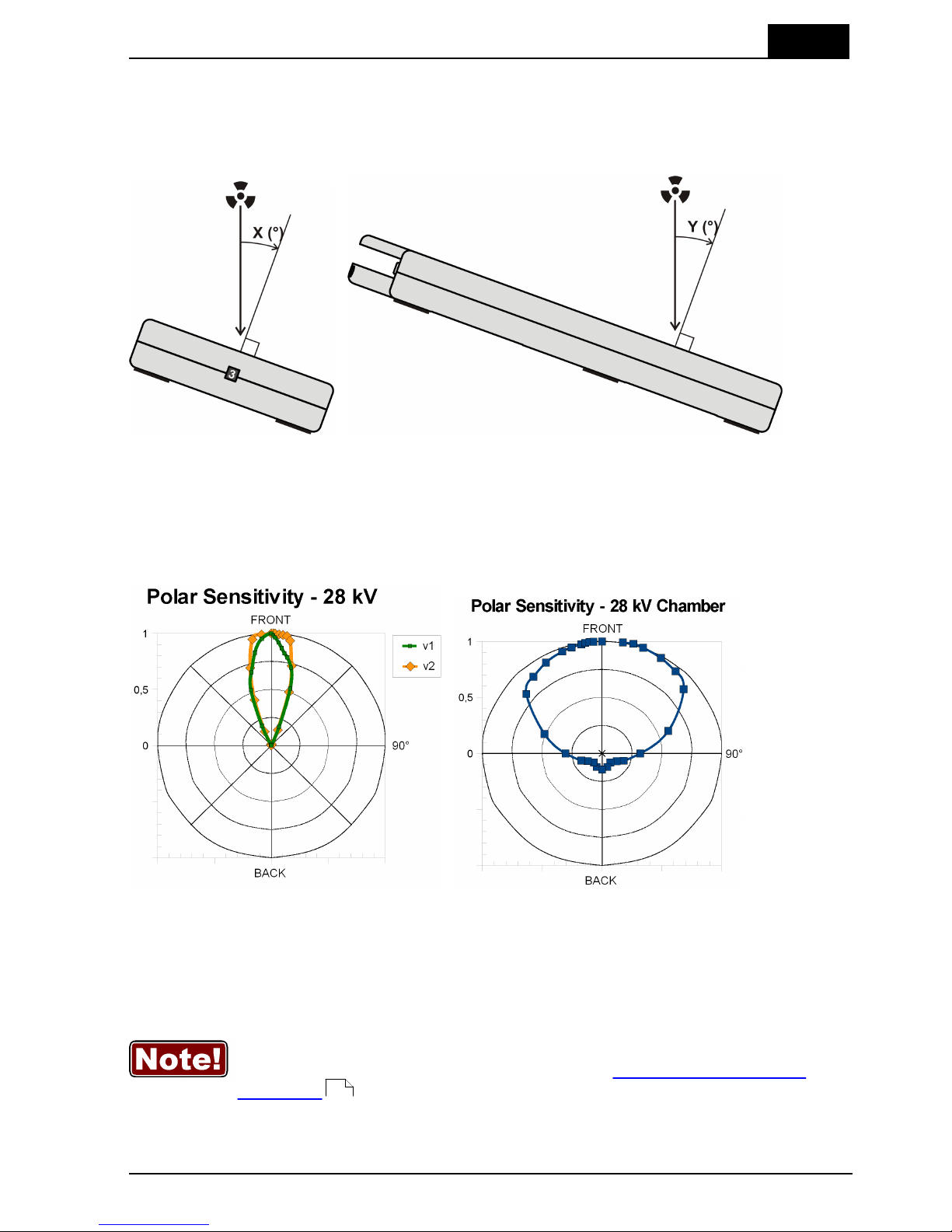
2.6.2.4 Angular Sensitivity, MPD
In this section you can see graphs of the typical angular sensitivity for dose measured
with the MPD at 28 and 70 kV. The setup is shown in figures below.
This "directional" behaviour makes it excellent for reproducible measurements, with
less influence by nearby spreading matter. This makes it possible to make accurate
HVL measurements even when measuring with "bad geometry", which is especially
interesting for mammography. To understand, please see the polar plot shown below.
The MPD is shown to the left, and a typical mammographic ion chamber to the right.
There are two different graphs, depending on the product version of your MPD. The
product version is the version number you can find on the label on the bottom of the
MPD. If the version of your MPD is 1.X, use the graphs marked v1. For 2.X and higher
use graphs marked v2.
For v1.X it is however important that you place the detector surface
perpendicular to the direction of the radiation source or that you make
corrections according to the tables in section Corrections for Angular
Sensitivity .
For radiography this is generally no problem, since most measurements are performed
in the middle of the field, perpendicular to the incident radiation.
143
Page 32

2. Description of the Barracuda
Hardware and Specifications
Barracuda & QABrowser Reference Manual
2012-10/4.3A
28
Page 33

2. Description of the Barracuda
Hardware and Specifications
2012-10/4.3A
29
Barracuda & QABrowser Reference Manual
2.6.3 Signal-Extension Module (MP-SEM)
2.6.3.1 General
The Signal Extension module is connected to the Multi-Purpose Module, and cannot
therefore be used separately.
Input and output signals:
· Analogue In
· Analogue Out
· Trig In
· Trig Out
The Analogue In makes it possible to sample a current signal via a LEMO triaxial
connector (e.g. tube current from a MAS probe, light from a L100 light detector, or tube
voltage from a voltage divider).
The Trig In makes it possible to trig the Barracuda from an external signal.
The Analogue Out gives the analogue radiation output measured by the Multi-Purpose
Detector, via a BNC connector attached to the Signal Extension Module.
The Trig Out makes it possible to trig an oscilloscope from the Multi-Purpose Detector.
2.6.3.2 Specifications, MP-SEM
General
Signal
Connector
Signal range
Analogue In
LEMO triaxial connector.
1 nA – 0.05 mA
Analogue Out
BNC out for the radiation output signal measured
with the MPD.
0 – 5 V
Trig In
BNC in for trig of the Barracuda from an external
signal.
Digital levels, 0/5 V
Trig Out
BNC out for trig of an external instrument on the
signal from the MPD.
Digital levels, 0/5 V
(No trig = 0 V, Trig = 5 V)
2.6.4 Electrometer Module (EMM)
2.6.4.1 General
The Electrometer Module have one or two electrometers with a LEMO triaxial
connectors for dose detectors, ionization chambers, mAs probes, or light detectors.
The module measures current, charge, time or pulses, and waveform.
Five different configurations are available:
· EMM-1Ch, single channel electrometer module
· EMM-2Ch, dual channel electrometer module
· EMM-Bias, single channel electrometer module with polarizing voltage (bias)
Page 34

2. Description of the Barracuda
Hardware and Specifications
Barracuda & QABrowser Reference Manual
2012-10/4.3A
30
between –300 to 300 V.
· EMM-BiasB, single channel electrometer module with polarizing voltage (bias)
between –300 to 300 V on either the triaxial connector or on a banana
connector.
· EMM-BiasW, single channel electrometer module with polarizing voltage (bias)
between –300 to 300 V on either the triaxial connector or on a banana
connector. Unipolar positive input only.
The single channel electrometer module EMM-1Ch measures exposure time and gives
the waveform with a resolution of 0.5 ms (low-speed mode). The QABrowser can show
the waveform for each exposure.
The dual channel electrometer module EMM-2Ch consists of two identical
electrometers as the one in EMM-1Ch. It can measure two electrometer signals
simultaneously. Exposure time is measured individually on the two channels.
The electrometer modules with polarizing (bias) voltage supply, EMM-Bias,
EMM-BiasB, and EMM-BiasW, are basically all the same electrometer as the one in
EMM-1Ch, but with an added bias voltage supply. They have floating input and the
bias voltage is selectable. The EMM-BiasB and EMM-BiasW also includes the option
to output the bias on a banana jack, for use with BNC/Banana type ion chambers. The
EMM-BiasW has a wider measurement range, but is unipolar only. All the bias
modules are only available as single channel electrometers.
2.6.4.2 Specifications, EMM
The inaccuracy is here defined as the root of the square sum of systematic errors,
which has not been eliminated, and random errors (dispersion around a mean value).
The calculation of the inaccuracy is based on 15 different measurements and with a
confidence level of 95 %. Of the total inaccuracy, random error is 20 % and general
inaccuracy is 80 %.
Note: Irradiation time is often called exposure time in daily use.
Reference conditions
Temperature
+18 °C to +23 °C
Relative humidity
50 %
Air pressure
101.3 kPa
Radiation quality
Radiography
Mammography
CT
70 kV, 2.5 mm Al
28 kV, 30 µm Mo
120 kV, 2.5 mm Al
Note: The reference conditions are given in reference to the IEC61674 standard.
General
Connector type
LEMO triaxial 0S, female-female-male
Page 35

2. Description of the Barracuda
Hardware and Specifications
2012-10/4.3A
31
Barracuda & QABrowser Reference Manual
Bias voltage (valid for EMM-Bias/BiasB/BiasW)
Range
-300 to +300 V (+20/-10 V)
Ripple
- Bias, BiasB
- BiasW
max 100 mV, typ. 30 mV
max 30 mV, typ. 20 mV
Max residual voltage (when LED off)
<1 V
Max continuous output current
32 µA (at ±300 V), not touchable
Atmospheric pressure sensor (valid for EMM-BiasW)
Measuring range
60 – 110 kPa (0.6 – 1 bar)
(resolution 0.1 kPa)
Inaccuracy (95-105 kPa)
±0.7 kPa
Inaccuracy (80-95 kPa)
±2.0 kPa
The EMM is a charge integrating device, making up to 2000 integrations per second.
This means that no "minimum" pulse width is needed to measure a charge, only the
minimum charge range needs to be reached. Current however, is calculated as the
average current for each integration cycle, see also Waveforms and Triggers . If the
pulse width is smaller than the integration time, the EMM will not be able to calculate
the peak current.
Measuring range and inaccuracy for charge
Parameter
Effective range
Total inaccuracy
Charge
- Unipolar (pos. or neg.)
- Bipolar
50 fC – >100 mC
at least ±50 mC
±1 % or ±12.5 fC
±0.5 % above 100 pC
Charge resolution
Reading×10-6 or 50 aC
–
Measuring range and inaccuracy for current and irradiation time
Parameter
Effective range
Total inaccuracy
Noise
Current EMM-1Ch/2Ch
- Unipolar (pos. or neg.)
- Bipolar
2 pA – 10 µA
-5 µA – +5 µA
±1 % or ±0.5 pA
±0.5 % above 100 pA
±50 fA
Current EMM-Bias/BiasB
- Unipolar (positive)
- Unipolar (negative)
- Bipolar
2 pA – 10 µA
-2 pA – -4.8 µA
-4.8 µA – +5.2 µA
±1 % or ±0.5 pA
±0.5 % above 100 pA
±50 fA
Current EMM-BiasW
- Unipolar (positive)
40 fA – 10 µA
(max neg. -40 nA)
±1 % or ±4 fA
±0.5 % above 100 pA
±1 fA
Max physical
input current
500 µA
–
–
Current resolution
–
102
Page 36

2. Description of the Barracuda
Hardware and Specifications
Barracuda & QABrowser Reference Manual
2012-10/4.3A
32
Parameter
Effective range
Total inaccuracy
Noise
- EMM-1Ch/2Ch/Bias/BiasB
- EMM-BiasW
Reading×10-6 or 100 fA
Reading×10-6 or 2.5 fA
–
Irradiation time
0.1 ms – 34000 s
1 – 65535 pulses
±1 % or ±0.5 ms
±1 pulse
Resolution
0.5 ms
For Current the specified Inaccuracy is valid for Irradiation times > 100 ms. Below
that, the inaccuracy of the time will also affect. This since the Current is calculated
as the Charge divided by the Irradiation time. Please see section Waveforms and
Triggers for further description.
Detailed current ranges
Parameter
Range
Total inaccuracy
Typ. noise
Current EMM-1Ch/2Ch
- High Sensitivity
- Unipolar positive
- Unipolar negative
- Bipolar
- Low Sensitivity
- Unipolar positive
- Unipolar negative
- Bipolar
2 pA – 95 nA
-2 pA – -90 nA
±2 pA – ±45 nA
1 nA – 10 µA
-1 nA – -10 µA
±1 nA – ±5 µA
±1 % or ±0.5 pA
±0.5 % above 100 pA
±1 % or ±10 pA
±50 fA
±500 fA
Current EMM-Bias/BiasB
- High Sensitivity
- Unipolar positive
- Unipolar negative
- Bipolar
- Low Sensitivity
- Unipolar positive
- Unipolar negative
- Bipolar
2 pA – 95 nA
-2 pA – -85 nA
±2 pA – ±47 nA
1 nA – 10 µA
-1 nA – -4.8 µA
4.8 µA – -1 nA/
1 nA – +5.2 µA
±1 % or ±0.5 pA
±0.5 % above 100 pA
±1 % or ±10 pA
±50 fA
±500 fA
Current EMM-BiasW
- Very High Sensitivity1
- Unipolar positive
- Moving average
- High Sensitivity
- Unipolar positive
- Low Sensitivity
- Unipolar positive
200 fA – 2.5 nA
40 fA – 2.5 nA
2 pA – 95 nA
1 nA – 10 µA
±1 % or ±20 fA
±1 % or ±4 fA
±1 % or ±0.5 pA
±1 % or ±10 pA
±5 fA
±50 fA
±500 fA
Note 1: To get access to the wide range of the EMM-BiasW, "very high" sensitivity must be
chosen. This alternative is only possible to choose in free run mode or in timed mode. See also
section Update Modes .
Pulses
Parameter
Range
Min. output peak current
- High Sensitivity
- High Sensitivity Ion Chambers
- Low Sensitivity
current (min. pulse width)
12.5 pA (4 ms) / 100 pA (0.5 ms)
50 pA (8 ms) / 400 pA (4 ms)
500 pA (4 ms) / 4000 pA (0.5 ms)
102
96
Page 37

2. Description of the Barracuda
Hardware and Specifications
2012-10/4.3A
33
Barracuda & QABrowser Reference Manual
Parameter
Range
- Low Sensitivity Ion Chambers
500 pA (8 ms) / 4000 pA (4 ms)
Pulse rate
- Normally
- Ion Chambers
0.5 – 100 Hz, resolution 0.5 Hz
0.5 – 25 Hz, resolution 0.5 Hz
Pulse width
4 ms - 2000 s
Duty cycle
5 - 95 %
Minimum pulse width
- Normally
- Ion Chambers
pulse width (min. peak current)
4 ms (12.5 pA) / 0.5 ms (100 pA)
8 ms (50 pA) / 4 ms (400 pA)
Pulse current
Same as for current (see above)
Smallest detectable charge/pulse
6.25 fC/pulse (4 ms) / 50 fC/pulse (0.5 ms)
Minimum ripple
(pulse top to bottom)
50 %
Irradiation time
1 – 65535 pulses, resolution 1 pulse
Note: Max dose/pulse depends on the pulse length.
Waveform recording time
At max sampling rate
320 ms (2 kSa/s)
At min sampling rate
40 s (16 Sa/s)
A total of 8 recording times are available, all separated by a factor of 2, i.e. 0.32, 0.63,
1.25, 2.5, 5.0, 10, 20, and 40 seconds.
The setting for Waveform recording time does NOT affect the Irradiation
time calculation from v3.0A of the firmware. This was an issue for earlier
versions.
2.6.4.3 Optional Detectors
Several different detectors, probes, and ion chambers from RTI Electronics can be
connected to the electrometer module (EMM). The measuring range are different
between the EMMs with bias and the two models without. The table below gives
measuring ranges for the most commonly used types.
The detector noise given is typical values at room temperature. The resolution can be
easily calculated by dividing the charge and current resolution, given in section
Specifications, EMM , by the typical sensitivity given for each detector below.
Example: An EMM-BiasW has a charge resolution of 50 aC and R100B has a
sensitivity of 55 µC/Gy. Thusly the R100B will have a dose resolution of 0.9 pGy.
Measuring range and inaccuracy
- R100B, Dose detector (typical sensitivity +55 µC/Gy)
Module type
Range
Inaccuracy
Typ. noise
EMM-BiasW
Air kerma (Dose)
100 pGy – 1.5 kGy
12 nR – 170 kR
±5 %
30
Page 38

2. Description of the Barracuda
Hardware and Specifications
Barracuda & QABrowser Reference Manual
2012-10/4.3A
34
Module type
Range
Inaccuracy
Typ. noise
Air kerma rate
(Dose rate)
(5 s moving average)
4 nGy/s – 76 mGy/s
460 nR/s – 8,7 R/s
26 µR/min – 520 R/min
1.6 mR/h – 31 kR/h
1 nGy/s – 76 mGy/s
±5 % or ±1 nGy/s
±5 % or ±100 nR/s
±5 % or ±6 µR/min
±5 % or ±360 µR/h
±5 % or ±250 pGy/s
±500 pGy/s
±100 pGy/s
EMM-1Ch/2Ch
Air kerma (Dose)
Air kerma rate
(Dose rate)
1 nGy – 1.5 kGy
0.12 µR – 170 kR
0.040 µGy/s – 160 mGy/s
4.6 µR/s – 18 R/s
0.26 mR/min – 1.1 kR/min
±5 %
±5 % or ±0.01 µGy/s
±5 % or ±1 µR/s
±5 % or ±0.06 mR/min
±5 nGy/s
EMM-Bias/BiasB
Air kerma (Dose)
Air kerma rate
(Dose rate)
1 nGy – 1.5 kGy
0.12 µR – 170 kR
0.040 µGy/s – 76 mGy/s
4.6 µR/s – 8,7 R/s
0.26 mR/min – 520 R/min
±5 %
±5 % or ±0.01 µGy/s
±5 % or ±1 µR/s
±5 % or ±0.06 mR/min
±5 nGy/s
Dose/pulse
1 nGy/pulse - 3 kGy/pulse
1
±5 %
-
Note 1: Max dose/pulse depends on the pulse length.
Note 2: For Kerma rate the specified Inaccuracy is valid for Irradiation times > 20 ms. Below that,
the inaccuracy of the time will also affect. This since the Kerma rate is calculated as the Kerma
(Dose) divided by the Irradiation time. Please see section Waveforms and Triggers for further
description.
Note 3: The standard calibration for the R100B is W/23 mm Al. This calibration was chosen since
the main use of the detector is to measure the dose to the image intensifier, after the phantom.
However, you can just as well use this probe for measurements of skin dose. The detector is very
linear in its energy response and will not be affected by a different filtration.
Pulses
Parameter
Range
Dose/pulse
1 nGy/pulse - 3 kGy/pulse
1
Pulse dose rate
Lower limit 10 µGy/s (70 mR/min), otherwise same
as for air kerma rate.
Min. output peak doserate
- High Sensitivity
- Low Sensitivity
Dose (min. pulse width)
0.23 µGy/s (4 ms) / 1.8 µGy/s (0.5 ms)
10 µGy/s (4 ms) / 73 µGy/s (0.5 ms)
Pulse rate
- Normally
0.5 – 100 Hz, resolution 0.5 Hz
Pulse width
4 ms - 2000 s
Duty cycle
5 - 95 %
Minimum pulse width
pulse width (min. peak doserate)
4 ms (0.23 µGy/s) / 0.5 ms (1.8 µGy/s)
Minimum ripple
(pulse top to bottom)
50 %
Irradiation time
1 – 65535 pulses, resolution 1 pulse
Note 1: Max dose/pulse depends on the pulse length.
102
Page 39

2. Description of the Barracuda
Hardware and Specifications
2012-10/4.3A
35
Barracuda & QABrowser Reference Manual
The table below shows the typical response for the R100B at standardised radiation
qualities, measured using RTI radiation quality code R1 (W/Al).
Radiation quality
Mean energy
air kerma
(keV)
Total
Filtration
(mm Al)
Air kerma measurement
PTB
ISO 4037
IEC 61267
HVL
(mm Al)
Factor kQ
(Rel. RQR 5)
DV40
RQR 2
26,38
2,49
1,42
1,087
DV50
RQR 3
29,0
2,46
1,77
1,044
DV60
RQR 4
32,0
2,68
2,19
1,013
DV70
RQR 5
34,8
2,83
2,571DV80
RQR 6
37,8
2,99
3,01
0,993
DV90
RQR 7
41,0
3,18
3,48
0,988
DV100
RQR 8
44,2
3,36
3,96
0,986
DV120
RQR 9
50,8
3,73
5,00
0,986
DV150
RQR 10
61,2
4,38
6,55
1,002
Note: Note: These values are typical values measured at PTB in Germany in 2009.
- R100, Dose detector (typical sensitivity -55 µC/Gy)
Module type
Range
Inaccuracy
Typ. noise
EMM-1Ch/2Ch
Air kerma (Dose)
Air kerma rate
(Dose rate)
1 nGy – 1.5 kGy
0.12 µR – 170 kR
0.040 µGy/s – 160 mGy/s
4.6 µR/s – 18 R/s
0.26 mR/min – 1.1 kR/min
±5 %
±5 % or ±0.01 µGy/s
±5 % or ±1 µR/s
±5 % or ±0.06 mR/min
±5 nGy/s
EMM-Bias/BiasB
Air kerma (Dose)
Air kerma rate
(Dose rate)
1 nGy – 1.5 kGy
0.12 µR – 170 kR
0.040 µGy/s – 76 mGy/s
4.6 µR/s – 8,7 R/s
0.26 mR/min – 520 R/min
±5 %
±5 % or ±0.01 µGy/s
±5 % or ±1 µR/s
±5 % or ±0.06 mR/min
±5 nGy/s
EMM-BiasW
N/A
N/A
N/A
Note 1: For Kerma rate the specified Inaccuracy is valid for Irradiation times > 20 ms. See Note
for R100B above.
- MAS-1B, Invasive mAs probe (sensitivity 1 nC/mAs)
Module type
Range
Inaccuracy
Typ. noise
EMM-1Ch/2Ch/
Bias/BiasB/BiasW
Tube charge
Tube current
Pulse tube current
0.001 mAs –
0.1 – 3000 mA
Lower limit 1 mA,
otherwise same as for tube
±1 %
±1 % or ±0.01 mA
±1.5 µA
Page 40

2. Description of the Barracuda
Hardware and Specifications
Barracuda & QABrowser Reference Manual
2012-10/4.3A
36
Module type
Range
Inaccuracy
Typ. noise
current.
Note 1: For Tube current the specified Inaccuracy is valid for Irradiation times > 100 ms. See
Note for R100B above.
- MAS-2B, Non-invasive mAs probe (sensitivity 1 nC/mAs)
Module type
Range
Inaccuracy
Typ. noise
EMM-1Ch/2Ch/
Bias/BiasB/BiasW
Tube charge
Tube current
Pulse tube current
0.1 mAs –
10 – 4000 mA
Lower limit 50 mA,
otherwise same as for
tube current.
±5 %
±5 % or ±2 mA (±3 %
at 250 mA)
±1 mA
Note 1: For Tube current the specified Inaccuracy is valid for Irradiation times > 20 ms. See Note
for R100B above.
- MAS-3, Non-invasive mAs probe (sensitivity -1 nC/mAs)
Module type
Range
Inaccuracy
Typ. noise
EMM-1Ch/2Ch/
Bias/BiasB
Tube charge
Tube current
Pulse tube current
0.001 mAs –
0.1 – 2000 mA
Lower limit 1 mA,
otherwise same as for
tube current.
±1 %
±1 % or ±0.02 mA
±5 µA
EMM-BiasW
N/A
N/A
N/A
Note 1: For Tube current the specified Inaccuracy is valid for Irradiation times > 20 ms. See Note
for R100B above.
- L100, Light detector (typical sensitivity -670 pA/nit or -200 pA/lx)
Module type
Range
Inaccuracy
Typ. noise
EMM-1Ch/2Ch/
Bias/BiasB
Luminance
Illuminance
0.03 – 72000 cd/m²
0.01 – 24000 lx
±5 % or ±0.006 cd/m²
±5 % or ±0.002 lx
±3 mcd/m²
±1 mlx
EMM-BiasW
N/A
N/A
N/A
Page 41

2. Description of the Barracuda
Hardware and Specifications
2012-10/4.3A
37
Barracuda & QABrowser Reference Manual
- L100B, Light detector (typical sensitivity 670 pA/nit or 200 pA/lx)
Module type
Range
Inaccuracy
Typ. noise
EMM-1Ch/2Ch/
Bias/BiasB
Luminance
Illuminance
0.03 – 72000 cd/m²
0.01 – 24000 lx
±5 % or ±0.006 cd/m²
±5 % or ±0.002 lx
±3 mcd/m²
±1 mlx
EMM-BiasW
Luminance
Illuminance
0.003 – 72000 cd/m²
0.001 – 24000 lx
±5 % or ±0.6 mcd/m²
±5 % or ±0.2 mlx
±0.3 mcd/m²
±0.1 mlx
- DCT10, CT ionization chamber (typical sensitivity 1.3 µC/Gym)
Module type
Range
Inaccuracy
Typ. noise
EMM-Bias/BiasB
CT air kerma
(CT Dose)
CT air kerma rate
(CT Dose rate)
0.4 µGym – 700 kGym
0.04 mGycm – 70 MGycm
16 µGym/s – 70 Gym/s
1.6 mGycm/s – 7 kGycm/s
12 Rcm/min – 34 MRcm/min
±5 %
±5 %
±5 % or ±1.6 µGym/s
±5 % or ±160 µGycm/s
±5 % or ±0.18 Rcm/min
±0.8 µGym/s
±80 µGycm/s
EMM-BiasW
CT air kerma
(CT Dose)
CT air kerma rate
(CT Dose rate)
40 nGym – 350 kGym
4 µGycm – 35 MGycm
1.6 µGym/s – 70 Gym/s
160 µGycm/s – 7 kGycm/s
1.2 Rcm/min – 34
MRcm/min
±5 %
±5 %
±5 % or ±160 nGym/s
±5 % or ±16 µGycm/s
±5 % or ±0.18 Rcm/min
±0.08 µGym/s
±8 µGycm/s
Note 1: For Kerma rate the specified Inaccuracy is valid for Irradiation times > 20 ms. See Note
for R100B above.
- Magna A600-MO52622 (1cc), Ionization chamber (typical sensitivity 38 nC/Gy)
Module type
Range
Inaccuracy
Typ. noise
EMM-Bias/BiasB
Air kerma (Dose)
Air kerma rate
(Dose rate)
1.5 µGy – 2 MGy
0.05 mGy/s – 250 Gy/s
0.3 R/min – 1500 kR/min
±5 %
±5 % or ±5 µGy/s
±5 % or ±40 µR/min
±1 µGy/s
EMM-BiasW
Air kerma (Dose)
Air kerma rate
(Dose rate)
150 nGy – 2 MGy
5 µGy/s – 250 Gy/s
30 mR/min – 1500 kR/min
±5 %
±5 % or ±500 nGy/s
±5 % or ±4 µR/min
±100 nGy/s
Note 1: For Kerma rate the specified Inaccuracy is valid for Irradiation times > 20 ms. See Note
for R100B above.
Note 2: The signal from an ion chamber is somewhat influenced by backscatter, if the chamber is
placed directly on for instance a table.
The table below shows the typical response for mammography of Magna
Page 42

2. Description of the Barracuda
Hardware and Specifications
Barracuda & QABrowser Reference Manual
2012-10/4.3A
38
A600-MO52622 at standardised radiation qualities, measured using RTI radiation
quality code M1.
Radiation quality
Mean energy
air kerma (keV)
Air kerma measurement
PTB
ISO 4037
IEC 61267
HVL (mm Al)
Factor kQ
(Rel. RQR-M2)
MV20
13,53
0,22
1,0018
MV25
RQR-M1
14,89
0,28
1,0110
MV28
RQR-M2
15,44
0,31
1
MV30
RQR-M3
15,7
0,33
1,0196
MV35
RQR-M4
16,28
0,37
1,0100
MV40
RQR-M5
16,71
0,39
1,0022
MV50
RQR-M6
17,3
0,42
0,9964
MH20
17,29
0,48
1,0109
MH25
RQA-M1
18,61
0,59
0,9781
MH28
RQA-M2
19,27
0,63
0,9873
MH30
RQA-M3
19,75
0,67
0,9869
MH35
RQA-M4
20,96
0,75
0,9862
MH40
RQA-M5
22,12
0,82
0,9833
MH50
RQA-M6
24,15
0,95
0,9877
Note: These values are typical values measured at PTB in Germany in 2007.
2.6.4.4 Typical Other Detectors
Several different detectors, probes, and ion chambers from other manufacturers can
be connected to the electrometer module (EMM). The measuring range are different
between the EMMs with bias and the two models without. The table below gives typical
measuring ranges for the some commonly used types.
To get the ranges in other units it is useful to know that 1 Gy corresponds to 114.1 R,
1 Gy/s corresponds to 114.1 R/s which equals 6846 R/min and 411 kR/h.
Measuring range and inaccuracy
- Radcal 6M, Ionization chamber (typical sensitivity 200 nC/Gy)
Module type
Range
Inaccuracy
EMM-Bias/BiasB
Air kerma
Air kerma rate
250 nGy – 330 kGy
0.01 mGy/s – 40 Gy/s
±5 %
±5 % or ±1 µGy/s (for time > 20 ms)
EMM-BiasW
Air kerma
Air kerma rate
25 nGy – 330 kGy
1 µGy/s – 40 Gy/s
5 mR/min – 250 kR/min
±5 %
±5 % or ±100 nGy/s (for time > 20 ms)
±5 % or ±0.7 µR/min (for time > 20 ms)
Page 43

2. Description of the Barracuda
Hardware and Specifications
2012-10/4.3A
39
Barracuda & QABrowser Reference Manual
- Generic 1 cm³, Ionization chamber (typical sensitivity 35 nC/Gy)
Module type
Range
Inaccuracy
EMM-Bias/BiasB
Air kerma
Air kerma rate
1500 nGy – 2 MGy
0.05 mGy/s – 250 Gy/s
±5 %
±5 % or ±6 µGy/s (for time > 20 ms)
EMM-BiasW
Air kerma
Air kerma rate
150 nGy – 2 MGy
6 µGy/s – 250 Gy/s
30 mR/min – 1500 kR/min
±5 %
±5 % or ±600 nGy/s (for time > 20 ms)
±5 % or ±4.2 µR/min (for time > 20 ms)
- Generic 3 cm³, Ionization chamber (typical sensitivity 100 nC/Gy)
Module type
Range
Inaccuracy
EMM-Bias/BiasB
Air kerma
Air kerma rate
500 nGy – 660 kGy
0.02 mGy/s – 80 Gy/s
±5 %
±5 % or ±2 µGy/s (for time > 20 ms)
EMM-BiasW
Air kerma
Air kerma rate
50 nGy – 660 kGy
2 µGy/s – 80 Gy/s
10 mR/min – 500 kR/min
±5 %
±5 % or ±200 nGy/s (for time > 20 ms)
±5 % or ±1.4 µR/min (for time > 20 ms)
- Generic 6 cm³, Ionization chamber (typical sensitivity 200 nC/Gy)
Module type
Range
Inaccuracy
EMM-Bias/BiasB
Air kerma
Air kerma rate
250 nGy – 330 kGy
0.01 mGy/s – 40 Gy/s
±5 %
±5 % or ±1 µGy/s (for time > 20 ms)
EMM-BiasW
Air kerma
Air kerma rate
25 nGy – 330 kGy
1 µGy/s – 40 Gy/s
5 mR/min – 250 kR/min
±5 %
±5 % or ±100 nGy/s (for time > 20 ms)
±5 % or ±0.7 µR/min (for time > 20 ms)
- Generic 15 cm³, Ionization chamber (typical sensitivity 500 nC/Gy)
Module type
Range
Inaccuracy
EMM-Bias/BiasB
Air kerma
Air kerma rate
100 nGy – 56 kGy
4 µGy/s – 16 Gy/s
±5 %
±5 % or ±0.4 µGy/s (for time > 20 ms)
EMM-BiasW
Air kerma
Air kerma rate
10 nGy – 56 kGy
0.4 µGy/s – 16 Gy/s
2 mR/min – 100 kR/min
±5 %
±5 % or ±40 nGy/s (for time > 20 ms)
±5 % or ±0.3 µR/min (for time > 20 ms)
Page 44

2. Description of the Barracuda
Hardware and Specifications
Barracuda & QABrowser Reference Manual
2012-10/4.3A
40
- Generic 60 cm³, Ionization chamber (typical sensitivity 2 µC/Gy)
Module type
Range
Inaccuracy
EMM-Bias/BiasB
Air kerma
Air kerma rate
25 nGy – 14 kGy
1 µGy/s – 4 Gy/s
±5 %
±5 % or ±0.1 µGy/s (for time > 20 ms)
EMM-BiasW
Air kerma
Air kerma rate
2.5 nGy – 14 kGy
0.1 µGy/s – 4 Gy/s
0.5 mR/min – 25 kR/min
±5 %
±5 % or ±10 nGy/s (for time > 20 ms)
±5 % or ±70 nR/min (for time > 20 ms)
- Generic 150 cm³, Ionization chamber (typical sensitivity 5 µC/Gy)
Module type
Range
Inaccuracy
EMM-Bias/BiasB
Air kerma
Air kerma rate
10 nGy – 5.6 kGy
0.4 µGy/s – 1.6 Gy/s
±5 %
±5 % or ±40 nGy/s (for time > 20 ms)
EMM-BiasW
Air kerma
Air kerma rate
1 nGy – 5.6 kGy
40 nGy/s – 1.6 Gy/s
0.2 mR/min – 10 kR/min
±5 %
±5 % or ±4 nGy/s (for time > 20 ms)
±5 % or ±30 nR/min (for time > 20 ms)
- Generic 300 cm³, Ionization chamber (typical sensitivity 10 µC/Gy)
Module type
Range
Inaccuracy
EMM-Bias/BiasB
Air kerma
Air kerma rate
5 nGy – 2.8 kGy
0.2 µGy/s – 0.80 Gy/s
±5 %
±5 % or ±20 nGy/s (for time > 20 ms)
EMM-BiasW
Air kerma
Air kerma rate
0.50 nGy – 2.80 kGy
20 nGy/s – 0.8 Gy/s
0.1 mR/min – 5 kR/min
±5 %
±5 % or ±2 nGy/s (for time > 20 ms)
±5 % or ±14 nR/min (for time > 20 ms)
Below you can see a graph showing the typical measurement ranges for ion chambers
with different volumes together with the electrometer EMM-BiasW.
Page 45

2. Description of the Barracuda
Hardware and Specifications
2012-10/4.3A
41
Barracuda & QABrowser Reference Manual
Standards and Compliances2.7
Hereafter you can find declarations of conformity, as well as documents describing the
intended use of the Barracuda system.
2.7.1 Waste Electrical and Electronic Equipment (WEEE)
The European Union Directive 2002/96/EC on Waste from Electrical and Electronic
Equipment (WEEE) places an obligation on manufacturers, distributors, and retailers
to take back electronics products at the end of their useful life.
The WEEE directive covers all RTI products being sold into the European Union (EU)
as of August 13, 2005. Manufacturers, distributors, and retailers are obliged to finance
the cost of recovery from municipal collection points, reuse, and recycling of specified
percentages per the WEEE requirements.
Instructions for disposal of WEEE by Users in the European Union
The symbol, shown left, is marked on the product, which indicates that this
product must not be disposed of with other waste. Instead, it is the user's
responsibility to dispose of the user's waste equipment by handing it over
to a designated collection point for the recycling of waste electrical and
electronic equipment. The separate collection and recycling of waste
equipment at the time of disposal will help to conserve
natural resources and ensure that it is recycled in a manner that protects human
health and the environment. For more information about where you can drop off your
waste equipment for recycling, please contact your local distributor from whom you
purchased the product.
Page 46

2. Description of the Barracuda
Standards and Compliances
Barracuda & QABrowser Reference Manual
2012-10/4.3A
42
2.7.2 Manufacturer's Declaration of Conformity
Page 47

2. Description of the Barracuda
Standards and Compliances
2012-10/4.3A
43
Barracuda & QABrowser Reference Manual
2.7.3 Intended Use
Page 48

2. Description of the Barracuda
Maintenance
Barracuda & QABrowser Reference Manual
2012-10/4.3A
44
Maintenance2.8
2.8.1 Barracuda Batteries
2.8.1.1 Exchanging Batteries
Serial number label
The battery compartment is found at the bottom
of the Barracuda cabinet.
To exchange batteries:
1. Unscrew the screw that holds the battery
compartment lid.
2. Place the batteries in the correct polarity
direction as indicated by the labels inside the
battery compartment. Placing the batteries in
the wrong direction will not damage the
Barracuda (unless you try to charge them) but
it will of course not function.
Battery compartment cover
Use six R6 (size AA) alkaline
or NiMH rechargeable batteries
3. Put back the lid and tighten the screw.
As always is the case for batteries, they should be removed if the device is not used for
a long time. They may leak acid that affects the battery compartment.
You will also find a label on the bottom side of the Barracuda. It tells you the
manufacturer's address, device type, version, conformity markings, and the serial
number of the product.
2.8.1.2 Charging the Batteries
If you use rechargeable batteries (NiMH), charging must be enabled from the handheld
computer (from the QABrowser). You should not try to charge other batteries than
rechargeable and the charging function must be disabled when alkaline batteries are
used. In future upgrades, the charging function will normally be turned off automatically
if alkaline batteries are installed. For now, make sure that the LED indicator is off when
charging is not allowed, i.e. when non-rechargeable batteries are inserted. Charging
may be manually turned on or can be set to automatically charge the batteries when
the external power supply is used. This you do from the QABrowser or oRTIgo. See
section Power Status for details of how to activate battery charging in the
QABrowser.
From version 1.3A of the Barracuda cabinet firmware, fast charging is supported.
During this a number of different charging cycles are used. You can see the charging
mode in use at present, by monitoring the orange charging LED, on the side of the
cabinet. In version 1.4A of the Barracuda cabinet firmware the charging is improved
further making it more compatible to different kinds of chargeable batteries.
87
Page 49

2. Description of the Barracuda
Maintenance
2012-10/4.3A
45
Barracuda & QABrowser Reference Manual
1. Deep charging. When the batteries are very discharged, a slower mode is used.
This is indicated by a 3 second cycle, with two short flashes.
2. Fast 1 A charging. This is indicated by a steady light from the LED.
3. Maintenance charging. A lower current is used to top the charging. This is indicated
by a 2 second cycle, where the light is on for 1.5 seconds.
4. Fully charged. The charging is on, but no actual charging current is used since the
batteries are fully charged. This is indicated by the LED being on for half a second
during a 3 second cycle.
The charging process is fully handled and monitored by the Barracuda cabinet
firmware, and when the charging is activated, the Palm or the PC does not need to be
attached for the charging to continue, even during the night (with chargeable batteries).
1! When you have started the software (QABrowser or oRTIgo) and enter
a measurement screen, the charging will be turned off. This is done to
minimize possible disturbances from the charging process when doing
low-level measurements. The charging process is reactivated as soon as
you leave the measurement screen.
2! Turning on and off the charging may give a varying battery level. Try to
keep keep charging turned on all the time when using chargeable
batteries. It is recommended to use chargeable batteries with 2100 mAh
to 2600 mAh rated capacity.
2.8.2 Updating the Barracuda Firmware
All firmware that is controlling the function of the Barracuda (in cabinet and modules) is
stored in flash memory to allow quick and easy update. The RTI Updater with the latest
firmware is always available free of charge on the RTI Electronics Web site at
http://www.rti.se. To update your Barracuda you must first download the latest version
and install it on a PC. The PC needs to have a serial interface or an USB to serial
adapter. If your system has bootloader v2.0A or newer, it can also be updated via the
USB interface.
A. You cannot use the Bluetooth Serial Module when updating your Barracuda. Please
use the normal serial cable that came with your Barracuda.
B. You will need to have access to an administrative account to install the software,
see section Windows Restricted User Accounts for details.
C. RTI Updater replaces the old Barracuda Updater software.
To update the Barracuda firmware (or bootloader):
1.
First download the latest version of the RTI Updater Setup from RTI Electronics Web
site.
2.
Unzip the file and run the file "RTI Updater Setup.exe" to install it on your PC. In the
end of the installation process you will get the question if you want to run that
updater immediately. If you have your Barracuda available you can connect it as
described in step #3. Answer "Yes" and continue with step #6.
3.
Connect the Barracuda. Use the serial or USB cable that came with your Barracuda
to connect your Barracuda to one of the serial (COM1 to COM99 is supported) or
Page 50

2. Description of the Barracuda
Maintenance
Barracuda & QABrowser Reference Manual
2012-10/4.3A
46
USB ports on the PC. Power on the Barracuda. Use the power supply to ensure that
no power failure occur during the update process. If you do not have a power supply
available, make sure you have fresh batteries in the Barracuda. You will get a notice
about that.
4.
Go to Start Menu | RTI Electronics | RTI Updater and select the RTI Updater.
5.
The RTI Updater starts and locates the Barracuda automatically if it is connected to
a COM or an USB port.
6.
If the Barracuda is found, the window in the figure above is shown. The different
modules are checked and after a while the start button is enabled. Click Start. If the
Barracuda cannot be found, a message with suggested solutions is shown.
7.
The updating process starts. The RTI Updater checks the current versions and
compares with the update. Modules with old firmware are automatically updated.
Page 51

2. Description of the Barracuda
Maintenance
2012-10/4.3A
47
Barracuda & QABrowser Reference Manual
8.
Note that storing the new firmware in the flash memory may take several minutes for
each module. The RTI Updater will indicate which modules have been updated.
9.
Power off the Barracuda and disconnect the serial cable when the program indicates
that everything is OK.
If you have any problem with your Barracuda after updating, re-install the firmware
again before contacting your local distributor or RTI Electronics. To re-install firmware
repeat step 1 to 9 above, but before performing step #6 go to the menu Settings and
select Always Overwrite.
If you want to see more details of what is updated, use the menu
Settings - Advanced, and you will see more information as shown in the
figure below.
Page 52

2. Description of the Barracuda
Maintenance
Barracuda & QABrowser Reference Manual
2012-10/4.3A
48
You normally also need to update the QABrowser and oRTIgo, when you
update the firmware. See section Updating the QABrowser and the
oRTIgo manual for details.
2.8.3 Managing Detector Calibrations
RTI Detector Manager is a special Windows software that gives an overview of all
calibrations for the detectors and probes in your system. You will find the RTI Detector
Manager on your Product CD, in the folder \Software\RTI Detector Manager\.,Start
the file RTI Detector Manager.exe by double-clicking it.
Select the instrument of interest (Barracuda)
and click OK.
If no instrument appears, check the
communication cable and that the
Barracuda is powered on, then click Rescan
.
91
Page 53

2. Description of the Barracuda
Maintenance
2012-10/4.3A
49
Barracuda & QABrowser Reference Manual
Next, the available detectors
are shown to the left.
When clicking a detector, the
available calibrations will
show up to the right (In this
case the MPD is
highlighted). The TV and TF
columns show an × if there
are calibrations for Tube
Voltage and/or Total
Filtration. The factor column
shows the calibration factor
(for dose in this case).
Here is another example
(R100). This type of detector
only contains a calibration
factor for dose.
2.8.4 Transferring Detector Calibrations
For the Barracuda, the calibration factors for the external detectors are stored inside
the cabinet.
If you have access to more than one cabinet you will need to transfer the detector
calibrations to the other cabinet(s) to be able to use all available detectors with all the
systems.
To transfer a detector:
1. Connect the cabinet, containing the calibrations, to a PC.
2. Start the RTI Detector Manager program (see Managing Detector Calibrations ).
3. Choose Main | File | Export.
48
Page 54

2. Description of the Barracuda
Maintenance
Barracuda & QABrowser Reference Manual
2012-10/4.3A
50
4. A tree-view of all the external
detectors is shown, with the
calibrations as "leaves". Mark the
detector or calibrations that you
want to transfer, and click Export.
Please note where your export file
is located.
5. Connect the other cabinet, start the RTI Detector Manager again, and choose Main
| File | Import.
6. The window shows all files exported, presently and earlier. Select the the proper file
(the one you just exported).
7. Mark the detectors and/or calibrations to be imported and click Import.
8. Click Store to Device to save the imported data to the Cabinet.
Done! You can use the same export file for importing detectors into more than one
cabinet.
2.8.5 Exchanging Modules
To change a Barracuda module you need only a small screwdriver. Before starting;
disconnect all detectors and the power supply. Make sure that the Barracuda is
powered off. Be careful not to power it on when you work with it if you have batteries
installed.
All modules have a specific "node" number. It is easier if this node number
corresponds to the slot where the module is mounted. Electrometer modules (all types)
have "2" as default node number. If more than one electrometer module is to be
installed in the same cabinet the node number of one of them must be changed.
Please contact your local distributor or RTI Electronics AB for guidance.
1. Power off the Barracuda
and disconnect all cables.
Page 55

2. Description of the Barracuda
Maintenance
2012-10/4.3A
51
Barracuda & QABrowser Reference Manual
2. Remove the side covers.
Start with the side where the
serial connector is located.
3. Use the screwdriver to
push out the pin that locks
the modules.
4. Use the screwdriver (or
better, a plastic pin to avoid
scratches) to carefully pull
out the module that should
be removed.
Page 56

2. Description of the Barracuda
Maintenance
Barracuda & QABrowser Reference Manual
2012-10/4.3A
52
5. Remove the module and
insert the new one.
6. Put back the pin that
locks the modules.
7. Put back the side covers.
Start with the side where the
power switch is located.
When sliding on the rubber
parts always start with the
back side (near the
modules). This makes sure
that the "notches" around
the modules are fitted
properly.
Page 57

2. Description of the Barracuda
Maintenance
2012-10/4.3A
53
Barracuda & QABrowser Reference Manual
8. Connect the MPD and the
Palm (or PC). Power on the
Barracuda.
Use the QABrowser System
Info to verify that the
new module is recognized
by the system.
86
Page 58

Description of the
QABrowser
Chapter 3
Page 59

3. Description of the QABrowser
Introduction to the QABrowser
2012-10/4.3A
55
Barracuda & QABrowser Reference Manual
3 Description of the QABrowser
Introduction to the QABrowser3.1
The QABrowser is a program that runs on a handheld computer. It will quickly guide
you through the measurements and tests of different X-ray systems. The QABrowser
controls the Barracuda and provides an intuitive user-interface. The instrument is
set-up based on the type of measurement you select. Two main measuring modes are
available; real-time display (RTD) and application mode.
In real-time display mode "virtual" meters are shown allowing you to read real-time
data. Up to six values can be measured and displayed at the same time. The built-in
applications allow you to do different tests such as accuracy, reproducibility, linearity,
HVL, and CTDI. There are also applications for viewbox test and monitor test using the
light detector. The QABrowser also allow you to look at waveforms and log data.
The text in this section assumes that you purchased your Handheld Display either
directly from RTI or a RTI dealer, which means that QABrowser is already installed and
configured on the Handheld Display. If you have purchased your handheld on your
own, then you first need to install the QABrowser to the handheld. How to do this for
Palm OS handhelds is described in the installation chapter in the HTML Help file on
your Product CD.
Starting the QABrowser3.2
Wireless through Bluetooth
1.
If you are using the Barracuda insert the Barracuda Serial Bluetooth Module.
2.
Turn on the meter.
3.
Launch the QABrowser by tapping on the QABrowser icon.
Please note that All needs to be selected at the top of the screen for the
QABrowser icon to be visible.
4.
The handheld will now search for available Bluetooth devices and show them to you,
select Current Discovery to limit the list to only show devices in range.
5.
Select your meter and press OK.
6.
If prompted enter the passkey for the meter which is “0000”.
Page 60

3. Description of the QABrowser
Starting the QABrowser
Barracuda & QABrowser Reference Manual
2012-10/4.3A
56
Cable or Holder
1.
Connect the cable to the Barracuda and to your handheld or connect the holder to
the Barracuda and position the handheld in the holder.
2.
Turn on the Barracuda
3.
If the QABrowser does not automatically launch, launch it manually tapping on the
QABrowser icon (see Bluetooth below).
If you experience any problems connecting through Bluetooth please see the
troubleshooting chapter , or visit the RTI website for more information.
Real-time Display and Waveforms3.3
This section will show how to make a measurement with the Barracuda and the
QABrowser. It is illustrated with an example using a radiographic X-ray unit. The
operation of the QABrowser has a general structure and the described procedures
applies also to other modalities. You can also follow this example using a
mammography or a dental system. You must then of course make the appropriate
selections of X-ray systems and your screen might look different from the screens
shown in this manual. However, you will be able to learn and follow the workflow of the
QABrowser. You will find specific information on how to perform different types of
measurements in the Measurements section.
Set up the Barracuda as described in topic Setting Up the Barracuda .
3.3.1 Using the Real-Time Display
There are two main measuring modes; Real-Time Display (RTD) and Applications in
the QABrowser. We will first see how to use the RTD to measure different parameters
and viewing waveforms. Earlier in the topic Setting Up the Barracuda was showed
how to set up the Barracuda system and how to start the QABrowser.
1. A list with different type of measurements is
shown. Note that the number of items in the list is
depending on the configuration of your Barracuda
system. Your list may have other choices than the
list shown here. To view items not visible, tap the
arrow or use the scroll button on the handheld
computer.
For this example, select Radiography.
188
16
16
Page 61

3. Description of the QABrowser
Real-time Display and Waveforms
2012-10/4.3A
57
Barracuda & QABrowser Reference Manual
2. A list with all different parameters are shown. You
can select to measure a single parameter or all at
the same time. In this example select All.
Note that the parameters shown here, are the
ones that are available with the current
configuration of your system.
A graphical picture of the cabinet's back side, showing the modules, is displayed on
the Select Detector screen. You can tap the different modules to view and select the
detector you want to use for that module. For the MPM, only the MPD detector is
available. You can also select beam quality when applicable and serial number if you
have several detectors of the same type.
Shows available
detectors for
selected module
Shows available
serial numbers for the
selected detector type
Selected module (MPM)
Selected module (EMM) and
input to use is indicated
3A. The next step is to select what you want to
measure and what detector you want to use. The
actual configuration for your Barracuda is now
shown. If your Barracuda has a MAS-probe you
can now decide if you want to measure mAs or not.
The MPD detector is selected to measure kVp,
time, dose, and dose rate. If you want to measure
mAs, tap also the EMM (electrometer module).
If you do not want to measure mAs or if you do not have a mAs probe, tap Select and
Page 62

3. Description of the QABrowser
Real-time Display and Waveforms
Barracuda & QABrowser Reference Manual
2012-10/4.3A
58
continue to step #7.
3B. When you tap the EMM, a list with available mAs
probes is shown. Select the mAs probe you want to
use.
3C. Tap Select to continue. The Barracuda is now set
up according to your choices.
4. The Real-Time Display (RTD) is now shown and you are ready to measure, see
figure below. The Barracuda is set to the most suitable settings for the selected type
of measurement, in this case radiography. The selected kV-range is 45-125 and the
beam quality (BQ) is W/3mmAl (reference beam quality). Depending on type of
measurement, you may have several kV-ranges and beam qualities to choose from.
For radiography, you have three different kV-ranges (35-75, 45-125, and 90-155) to
select between.You will have four displays on this screen if you do not have/use a
mAs-probe and six if you selected to measure mAs. The manual for the mAs-probe
explains how to connect it.
Change
kV-range by
tapping here
Here measurement
indicators are shown.
Change unit by tapping
the unit text
Change Beam Quality by
tapping here
Tap here to reset detectors
When you tap a unit, a list to select unit from is
shown. Tap the desired unit or tap Cancel to
keep the present one.
Page 63

3. Description of the QABrowser
Real-time Display and Waveforms
2012-10/4.3A
59
Barracuda & QABrowser Reference Manual
The first thing to do before starting to measure, is to verify that the Multi-Purpose
Detector is placed correctly in the X-ray field. A special function is available to do
this. Position the MPD under the tube as described in the topic Setting Up the
Barracuda .
The Position Check is usually not necessary for Radiography, but often
essential for the other modalities, in order to get more accurate
measurements. To skip go to 8.
5. Tap the kV-range selector, and a list will appear, as
shown left. Tap Check[C] to select the MPD
position check.
6. The Position Check screen is now shown. Set up
the X-ray generator. Recommended kV is:
· Radiography: use 70 kV
· Mammography: use 28 kV
· CT: use 120 kV (or any other available kV
setting).
7. Make an exposure. A message will be shown. If the
detector is incorrectly aligned, the QABrowser will
tell you to re-position the detector. For a small
misalignment a correction factor is applied and you
are allowed to continue without re-positioning the
detector. This message disappears automatically if
the position is OK.
If the displayed number is between 0.950 and 1.050 the position is acceptable and a
correction factor will be applied to correct the position to "1.000". The correction factor
is valid until you perform this check again or until you quit the QABrowser. It is
recommended to perform the position check after any repositioning of the detector or
after change of target/filter combination when measuring on a mammography unit.
You are now ready to make the first exposure. Set the generator to 80 kV. Make sure
that the correct kV range is used, in this case "R1[4] 45-125". When you make the first
exposure, the Barracuda will evaluate what kind of waveform it is (DC/HF,
16
Page 64
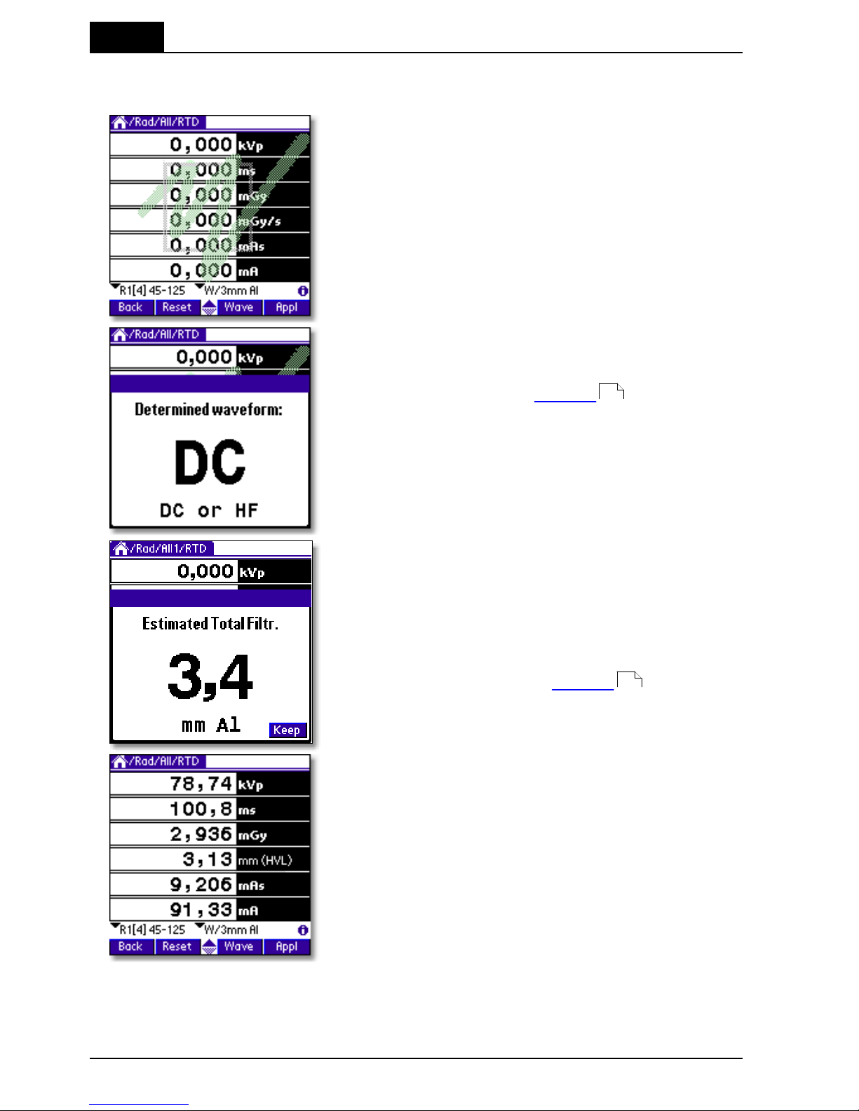
3. Description of the QABrowser
Real-time Display and Waveforms
Barracuda & QABrowser Reference Manual
2012-10/4.3A
60
3-phase/12p, 3-phase/6p, or 1-phase) and the total filtration. This is done for all
measurement types but mammography. Default values are "DC/HF" and 3.0 mm Al.
8. Make an exposure. Every time the Barracuda
recognizes an exposure the RTI logo is
superimposed on screen for a short while.
The Barracuda analyses the waveform and shows the
result automatically after the first exposure. If the
result is incorrect the actual waveform type needs to
be set manually, see topic Settings for more
information.
The Barracuda measures the total filtration for each
exposure (for all measurement types except
mammography). It is shown automatically after the
first exposure.
If you want the QABrowser to lock this value and not
estimate it again for the following exposures, tap
Keep. You can also enter the total filtration manually
under the settings, see topic Settings for more
information.
Up to six values can be shown simultaneously.
Measured kVp, dose, and dose rate values are
compensated depending on actual total filtration
(between 1.5 - 38 mm Al) and waveform type.
The display looks different depending on the type of parameter you selected in step
#3 and if you are using a mAs probe or not. In the pictures below you can see how
the screen looks if you do not measure mAs and if you select just Tube voltage.
62
62
Page 65

3. Description of the QABrowser
Real-time Display and Waveforms
2012-10/4.3A
61
Barracuda & QABrowser Reference Manual
The single parameter displays are large to allow reading from distance. In the single
parameter displays complementary values may be shown (in the figure above
exposure time and total filtration). Which complementary values that are shown
depends on the selected parameter. Up to three complementary values can be shown.
If any of the displayed values is not possible to compensate or cannot be measured
with full accuracy the symbol is displayed at the top of screen. If the symbol is
displayed you can tap it with the pen to display more information.
3.3.2 Waveforms - Acquiring and Viewing
Waveforms are always captured for each exposure you make. Up to three waveforms
are simultaneously captured and visualized with the QABrowser. The following
waveforms can be measured depending on configuration and selected type of
measurement:
· tube voltage (kVp) with the MPD
· dose rate with the MPD
· dose rate with a detector (R100 or an ion chamber) connected to an electrometer
module (EMM).
· tube current (mA) with a mAs-probe connected to an electrometer module (EMM).
For the Electrometer Charge and Current measurement types, it is also possible to get
the actual current input waveform.
In Continuous update mode you also have the possibility to restart the waveform
collection during the measurement. Every time you tap Hold, the waveforms are
acquired again. When you do this, the previously acquired waveforms will be replaced.
The waveforms available for viewing will be the ones from you last Hold tap.
To view waveforms after the exposure:
Page 66

3. Description of the QABrowser
Real-time Display and Waveforms
Barracuda & QABrowser Reference Manual
2012-10/4.3A
62
1. Tap Wave (or press the corresponding
button). The waveform screen appears and
waveforms are displayed. The kV waveform
takes a few seconds to calculate before it is
displayed.
2. The waveforms are displayed and you can
use the pen to move the cursor. Corresponding
cursor values are shown under the waveforms.
3. Tap kVp, Dose…, or mA once to hide/show
the corresponding waveform.
4. You can now make new exposures without returning to the real-time display. The
old waveforms are then erased, and the new ones are shown. If the
waveform recording time is much longer than the exposure time, you may only get a
part of the waveform, since the Barracuda is still capturing the waveform. Then you
can go back to the RTD and tap Wave again, when the waveform recording time has
passed, to get the full waveform.
3.3.3 Measurement Settings
As mentioned before all settings of the Barracuda are done automatically when you
select type of measurement. For example, when you choose fluoroscopy the detector
sensitivity is set to high. However, there might be situations where the default settings
cannot be used and settings must be adjusted. Use Settings to adjust the Barracuda
when necessary. The figure below shows how to access this function.
Tap this symbol to open the screen with
Settings for the Barracuda and the
various detectors
When you tap the symbol the Settings screen is shown. This can also be
Page 67

3. Description of the QABrowser
Real-time Display and Waveforms
2012-10/4.3A
63
Barracuda & QABrowser Reference Manual
accomplished by tapping the icon on the graffiti area (or the Tungsten T3, T5, TX
status bar). What is shown here is dependent on selected parameter(s) and used
detectors.
Conditions
Shows general conditions for the measurement. Different values can be shown
depending on selected measured parameter. Details about the Condition screens can
be seen in Settings - Conditions .
Tap Conditions to show the drop-down list with other
settings:
Barracuda: General settings for the Barracuda.
MPD: Specific settings for the MPD detector.
MAS-2: Specific settings for the external probe.
As seen, all detectors in use will show up in this list.
Barracuda
Shows general settings for the Barracuda. You can find
information about the different parameters in Settings -
Barracuda .
64
68
Page 68

3. Description of the QABrowser
Real-time Display and Waveforms
Barracuda & QABrowser Reference Manual
2012-10/4.3A
64
MPD
Shows specific settings for the MPD detector as well as
the serial number.
You can find information about the different parameters
in Settings - MPD .
MAS-2
Shows specific settings and the serial number for the
detector that is connected to the electrometer module
(EMM). In this case it is a MAS-2 probe.
You can find information about the different parameters
in Settings - Other Detectors .
Default values for the settings are depending on the selected type of measurement
and detector.
Tap Back to return to the real-time display.
3.3.3.1 Settings - Conditions
Here general conditions for the measurements are shown. Different values can be
shown depending on selected measured parameter.
Conditions - TF and Waveform
These are parameters of the X-ray generator which
influence the measurements. The Barracuda can
measure these, or you can set them yourself.
Total Filtr.
Shows actual total filtration value. Estimate means that a new
estimation will be performed at next exposure and the values will be
displayed on screen.
70
72
Page 69

3. Description of the QABrowser
Real-time Display and Waveforms
2012-10/4.3A
65
Barracuda & QABrowser Reference Manual
Waveform
Shows the actual waveform type. Determine means that a new
analyse of the waveform will be performed for the next exposure.
The result will be displayed on screen. The waveform types
supported are:
- DC/HF
- Single Phase
- 3-Phase 6-Pulse
- 3-Phase 12-Pulse
- AMX-4
- Pulsed
The first four can be automatically determined when Estimate is
chosen. The selected or set waveform is also shown with a symbol
on the Real-Time Display, see Indicators and Symbols .
AMX-4
The difficulties when measuring tube voltage on a GE AMX-4 is a well-known problem.
Due to high kV ripple at a frequency of 2 kHz it is hard for most non-invasive
kVp-meters to follow the kV waveform correctly.
This waveform type has an agreement with measurements made with the Keithley
Triad System 37946C mobile filter pack (50-135 kV), which is the only filter package
recommended by GE. According to GE, the use of the standard Keithley 37617C W-R
filter pack (50-150 kV) is not good enough. The results have further been verified with
measurements with a traceable high voltage divider that has sufficient bandwidth to
accurately follow the kV ripple from the AMX-4.
Therefore it is important to select the AMX-4 waveform
under Settings | Conditions.
More about the AMX-4 correction can be found in the
Application Note 1-AN-52020-1 from RTI Electronics
AB.
Pulsed
This waveform type should be used for pulsed fluoroscopy especially when the pulses
do not have a "good" square waveform shape. The exposure time must be longer than
the selected recording time when using this waveform type. Pulsed waveform type is
89
Page 70

3. Description of the QABrowser
Real-time Display and Waveforms
Barracuda & QABrowser Reference Manual
2012-10/4.3A
66
selected under Settings | Conditions in the same way as the AMX-4 waveform type.
Conditions - TP-factor
If an ion chamber is used, temperature and pressure
can be specified to get correct dose measurements.
The MPD and other semiconductor detectors
are virtually not affected by temperature and pressure.
Tapping Reset will set the T and P back to its default
values (101.3 kPa and 20 °C) resulting in a TP Factor
of 1.000.
The TP Factor is calculated as follows:
TP = P0/P × T/T0
where: P0 and T0 are the reference air pressure and absolute air temperature
(normally P0=101.3 kPa and T0=293 K [20 °C])
T and P are the actual absolute air temperature and pressure in the same
units (kPa and K)
Temperature
This value is used to calculate the TP-factor when ion chambers
are used. Temperature can be specified in Kelvin, degrees
Celsius, or degrees Fahrenheit. Unit is chosen in the QABrowser
Setup, under Units.
Pressure
This value is used to calculate the TP-factor when ion chambers
are used. Air pressure can be specified in several different units.
Unit is chosen in the QABrowser Setup, under Units.
Please note that the pressure easily changes by 10 %. For the same effect from
temperature, it must change 30 °C (or 54 °F).
If you have an EMM-BiasW module, the atmospheric
pressure is automatically measured when changing
Type of Measurement or starting a Favourite.
Page 71

3. Description of the QABrowser
Real-time Display and Waveforms
2012-10/4.3A
67
Barracuda & QABrowser Reference Manual
Conditions - Pulse rate
Conditions - Pulse rate
If a pulsed mode is used, like pulsed fluoroscopy or
pulsed radiography (cine) the pulse rate can be
specified in pulses per second (same as Hz). This
allows you to get a dose/pulse reading even if the
detector used (e.g. ion chamber) is too slow for the
Barracuda electrometer to detect the pulses. A
solid-state detector, like the R100, is however fast
enough to detect the frequency even for very low-level
signals.
Conditions - Compression paddle
For mammography, it is sometimes easier to do
measurements with the compression paddle in the field.
The compression paddle will however normally affect
the Barracuda kV and dose reading. With this check
box, all the measured values (kV, dose and HVL) will be
corrected according to what the user has selected. The
default setting the first time you start the software is
without the compression paddle in the field.
When selected you will see the settings for Scatter
factor and Equivalent thickness. The thickness is given
in mm Al, if you do not know, ask the manufacturer or
make a comparison with Aluminium filters. When this
option is active, an indicator on the RTD screen
indicates that this feature is on.
Scatter factor
If an ion chamber is positioned just below the compression
paddle, the measured dose will rise, because of side scattering
from the compression paddle material. The effect of this is
depending on the ion chambers angular dependence. Since the
MPD is almost insensitive to this, you can put a number here to
compare readings from the MPD with readings from an ion
chamber. See also section Average Glandular Dose, AGD (MGD)
.
When this is activated a red compression paddle indicator will
show in the top right corner of the RTD screen ( ).
144
Page 72

3. Description of the QABrowser
Real-time Display and Waveforms
Barracuda & QABrowser Reference Manual
2012-10/4.3A
68
Equiv. thickness
The given equivalent compression paddle thickness is used to
increase the accuracy of dose measurements when dose is
measured below the compression paddle. It is given in equivalent
thickness of aluminium.
This feature can also be used if you have additional
filtration in the beam. Add the equivalent thickness of aluminium.
Conditions - Beam Correction
Sometimes you may want to make comparable
measurements with known mechanical setup. For
instance if you want to emulate ion chamber
measurements in a particular scattering situation. Then
you can set a Beam Correction factor to get that
reading. In this case the ion chamber measures an
extra 25 % from side and back-scatter. Using this factor
makes the readings to be the same. It is of course
important that the mechanical setup in these cases are
the same. When this function is activated a red
horisontal indicator will show in the top right corner of
the RTD screen ( ).
Here you can see an example of
a holder that is used for some
customers to replace ion
chambers in ready-made fixtures.
3.3.3.2 Settings - Barracuda
Here general measurement settings for the Barracuda
are shown.
Post Delay
The post delay time defines how long time the Barracuda shall
wait and "look for more" after detecting what can be considered to
be "the end of the exposure". Default value is 250 ms. The
Page 73

3. Description of the QABrowser
Real-time Display and Waveforms
2012-10/4.3A
69
Barracuda & QABrowser Reference Manual
post-delay is necessary when measuring on units with some kind
of pre-pulse or for pulsed exposures.
The post delay can be set to: Off, 25 ms, 250 ms, 1 s, or Other…
(0-9999 ms).
The default value is set according to selected type of
measurement, see section Measurement Type Settings .
Trig source
This setting makes it possible to define the trig source for the
electrometer module.
Available settings are:
· Individually, each detector starts to measure individually
when it detects a signal.
· MPD, the measurement of all parameters (all modules) start
when the MPD starts to measure.
Default value is always MPD when it is used. This is the
recommended trig source.
Trig level (time)
Here you can set the level used for irradiation time measurements.
"Trig level (time)" (TL) is normally set to 50 % of the peak
waveform (SPEAK), but can be set between 10 and 90 %. The
irradiation time is then calculated as the end time minus the start
time.
· The start time is the first time the signal goes above TL×S
PEAK
.
· The end time is the last time the signal goes below TL×S
PEAK
.
See example below.
Update
This setting defines when Barracuda shall send
measured values to the QABrowser.
Four different alternatives are available:
· After exp., the QABrowser receives a new value
when the exposure terminates.
· Continuous, the Barracuda is continuously sending
data as long as radiation is detected. Displays in the
QABrowser are updated about every four seconds.
Typically used for Fluoroscopy.
· Timed, the user sets a measurement time. The user
95
Page 74

3. Description of the QABrowser
Real-time Display and Waveforms
Barracuda & QABrowser Reference Manual
2012-10/4.3A
70
then starts the measurement and the Barracuda will
measure all radiation received during the
measurement time, without any trig levels. When the
time has passed, a reading will be presented.
· Free run, the Barracuda will continuously measure
the radiation without any trig levels.
Default value is set according to selected type of
measurement and this parameter normally never needs
to be manually changed, unless really low-level
measurements are to be accomplished. See the sections
Measurement Type Settings and Update Modes
for more information.
Waveform
rec. time
The QABrowser is able to show a total of 640 samples.
The sampling interval is normally 0.5 ms, giving a total
measurement window of 320 ms. By increasing the
sampling interval, a sampling window up to 40 seconds,
or even more, can however be selected. This is very
handy when longer exposure times are used and the
waveforms need to be viewed.
The available range is however higher for some slower
detectors, typically ion chambers, and also when "Very
high" sensitivity is chosen for EMM-BiasW. See section
Update Modes for more information. The default value
is set according to selected type of measurement, see
section Measurement Type Settings .
Start after delay
When this is selected, the waveform recoding will start
after the set delay. This can be useful if you want to study
a phenomenon that occurs after the normal waveform
recording time. When this is selected the electrometer
waveform will not show simultaneously and you will get a
warning that the irradiation time measurement is
inaccurate. The reason for this is that the Barracuda
needs the waveform from start to be able to accurately
calculate the irradiation time.
This is a temporary setting, and it will be turned off when
you exit the RTD.
3.3.3.3 Settings - MPD
Here general measurement settings for the MPD are
shown. You can find information about the different
parameters below.
95 96
96
95
Page 75

3. Description of the QABrowser
Real-time Display and Waveforms
2012-10/4.3A
71
Barracuda & QABrowser Reference Manual
If Normalize to distance is checked, another section is
shown. See description below.
Sensitivity
Dose/TF
This is used to set the dose and TF sensitivity for the MPD.
The sensitivity can be set to: Low, High, and Very High.
Default value is set according to type of measurement.
Sensitivity kV
This is used to set the kV sensitivity for the MPD.
The sensitivity can be set to: Low and High.
Default value is set according to type of measurement selected.
Delay
The delay time defines how long time the Barracuda shall wait before
starting to measure kVp after that radiation has been detected.
The delay can be set to: Off, 5 ms, 25 ms, 100 ms, 500 ms, 1 s, 2 s,
or Other…(0-9999 ms)
The default value is set according to selected type of measurement,
see section Measurement Type Settings .
Window
This gives the possibility to define a fixed time that Barracuda
measures kVp after that the delay time has expired.
The window can be set to: Infinite, 5 ms, 10 ms, 25 ms, 100 ms, 200
ms, or Other…(0-9999 ms)
Default value is always "Infinite".
Normalize to
distance
If Normalize to distance is checked, you have the option to normalize
the dose reading to any given distance. Here you can enter your
Source to Detector Distance (SDD) and a normalizing distance (SDD
Norm), that you want the dose normalized to. When this is activated
a blue N will show in the top right corner of the RTD screen.
95
Page 76

3. Description of the QABrowser
Real-time Display and Waveforms
Barracuda & QABrowser Reference Manual
2012-10/4.3A
72
3.3.3.4 Settings - Other Detectors
Here general measurement settings for other detectors
or probes are shown. You can also see which module
the detector is connected to and the detector's serial
number. Note that different detectors have different
options.
Sensitivity
This is used to set the sensitivity for the electrometer module. The
sensitivity can be set to: Low, High, and Very High.
The Very High option is only available for the Barracuda EMM-BiasW.
Default value is set according to selected type of measurement and
used detector.
Threshold
This is used to set the trig level. It can be set to Low (½×), Normal, 2×,
4×, and 8×. The default value is "Normal". The setting "Low" can be
used if low signals are measured and a lower trig level is required.
However, the risk for false triggering increases when "Low" is used.
To avoid false triggering in a noisy environment use one of the
"higher" threshold levels.
Normalize to
distance
Note: Only for dose detectors!
If Normalize to distance is checked, you have the option to normalize
the dose reading to any given distance. Here you can enter your
Source to Detector Distance (SDD) and a normalizing distance (SDD
Norm), that you want the dose normalized to. When this is activated
an "N" symbol will show on the RTD screen.
QABrowser Applications3.4
There are several built-in applications available to simplify different standard QA tests.
Some applications are general and are available for many types of measurements and
parameter selections, while other are very specific for a certain parameter. Applications
can be used to analyse one or several parameters at the same time.
The first example shows how the accuracy of kVp can be tested using the built-in
application Accuracy. The second example shows a multi-parameter Accuracy
application.
Page 77

3. Description of the QABrowser
QABrowser Applications
2012-10/4.3A
73
Barracuda & QABrowser Reference Manual
3.4.1 The Accuracy Application (single-parameter)
1. Go to the real-time display that displays
only kVp. Tap Appl or press the
corresponding button to open the
application list.
It is recommended to make one exposure
first to analyse the waveform and estimate
the total filtration.
2. The Select application screen lists the
available applications for selected Type of
measurement and Selected parameter.
For kVp, only Accuracy and
Reproducibility are available.
Choose Accuracy by tapping it with the
pen. You can also use the scroll button to
highlight Accuracy and then press the
button that corresponds to Select (the
right-most button).
3. The accuracy application is shown on the
screen. The set values (for kVp) are
stored in a Set-value list. You can modify
the list or individual values.
To modify an individual set value tap with
the pen on it. In this case tap 60.
Page 78

3. Description of the QABrowser
QABrowser Applications
Barracuda & QABrowser Reference Manual
2012-10/4.3A
74
4. An input box is shown at the bottom of the
screen allowing input of a new set value.
Enter a new value using the pen on the
graffiti area, then tap OK.
Tap Cancel to leave without modifying the
set value.
If you want to, edit or view the complete set
value list. Then tap , at the top
of the screen, or the Menu icon (the lower
icon to the left of the graffiti area) and select
Options | Edit Set Value List from the
pull-down menu.
You can now change/delete/insert values in
the set value list for current application. Use
the graffiti area to enter new values.
Tap OK to save changes or Cancel to return
to the application without changing the list.
5. Make exposures according to the set
values. Measured values are shown and
the inaccuracy of kVp is calculated and
displayed for each exposure. You can
always tap a previous row and redo that
exposure. Number of exposures and
maximum inaccuracy is shown at the
lower part of the screen. Tap Graph to
show result in a graph.
Page 79

3. Description of the QABrowser
QABrowser Applications
2012-10/4.3A
75
Barracuda & QABrowser Reference Manual
The result is plotted in a graph together with
the maximum and minimum accepted limits
(dotted lines) for the tested parameter. The
limits are defined in the Setup, see topic
QABrowser Setup/Regulations for more
information. You can use the pen or buttons
to move the cursor to view result for
individual points.
3.4.2 The Accuracy Application (multi-parameter)
It is also possible to test several parameters at the same time. As an example
Radiography/All/Accuracy is used.
1. Tap Appl to activate the application
screen.
2. Available applications for Radiography/All
are shown. Choose Accuracy by tapping
it with the pen. You can also use the scroll
button to highlight Accuracy and then
press the button that corresponds to
Select (the right-most button).
84
Page 80

3. Description of the QABrowser
QABrowser Applications
Barracuda & QABrowser Reference Manual
2012-10/4.3A
76
3. The multi-parameter application is shown.
In this mode only one exposure at a time
is shown on the screen. You can here
also change individual set values or the
complete list for a specific parameter.
To modify an individual set value tap with
the pen on it. In this case tap 60.
4. An input box is shown at the bottom of the
screen allowing input of a new set value.
Enter a new value using the pen on the
graffiti area, then tap OK.
Tap Cancel to leave without modifying the
set value.
If you want to, edit or view the complete set
value list. Then tap , at the top
of the screen, or the Menu icon (the lower
icon to the left of the graffiti area) and select
Options | Edit Set Value List from the
pull-down menu.
You can now change/delete/insert values in
the set value list for current application. Use
the graffiti area to enter new values.
Tap OK to save changes or Cancel to return
to the application without changing the list.
Page 81

3. Description of the QABrowser
QABrowser Applications
2012-10/4.3A
77
Barracuda & QABrowser Reference Manual
5. Set the generator according to the set values. Make an exposure.
Measured and calculated values are shown for two seconds before the set values
for the next exposure is shown. Make all exposures in the list. You can always go
back to previous exposures by tapping the arrow symbols . You can at any time
go back and redo a previous exposure.
6. Perform all exposures in the list.
7. You can look at the result graphically for each parameter tested. Highlight a
parameter by tapping it with the pen (not the set value) and then tap Graph or
press the corresponding button. The accuracy limits (dotted lines) in the graph
are defined in the QABrowser Setup, see topic QABrowser Setup/Regulations
.
Data Logging3.5
The QABrowser can log data and save data in files on the handheld computer.
Prepare the data log by first entering some basic information about the measurement.
Open the pull-down menu and select Setup or go to the Start Screen and tap Setup.
From the Setup menu select Log.
84
Page 82

3. Description of the QABrowser
Data Logging
Barracuda & QABrowser Reference Manual
2012-10/4.3A
78
The first thing to do is to start a log session. This is done from Options | Start Log on
the pull-down menu. You open the pull-down menu by tapping or by
tapping the Menu icon to the left of the graffiti area. Activate the log by tapping Start
Log. You will now be asked to enter a Log Note. This can be some kind of information
that you want to save in the log file. Continue with OK or Don't Show if you do not
want to save a note.
The log is now activated and the result of
each exposure is being saved in the log file.
The active log is indicated with the animated
black symbol at the top of the screen. This
symbol is in motion as long as the data
saved in the log file. Now make some
exposures at some different kV stations.
In After exposure or Timed update modes a value will be written to the log file each
time the exposure indication is shown. For Continuous update mode a value will be
stored each time you tap the Hold button. In applications, the log values are stored
when you exit the application. This means that you can start the log after you have
done your measurements and still get all data to the log.
If you want to pause the log temporarily just select Options | Pause Log on the
pull-down menu. The log is still active but no data is saved in the file (the log indication
"freezes"). This makes it possible to make exposures that are not saved in the log file.
To resume data logging (into the same file) select Options | Pause Log again. If you
got bad reading, you can also use the pull-down menu time Options | Delete Last
Logged Value to delete single values from the log.
Note that when measuring in an Application, the data will not be stored in the log file
until you exit the Application. That means that even if you start the log after you have
begun measuring you will still get all the application measurements in the log file.
Page 83

3. Description of the QABrowser
Data Logging
2012-10/4.3A
79
Barracuda & QABrowser Reference Manual
You can stop and save the log from the pull-down menu by selecting Options | Save
Log. The contents of the log file is displayed. You can now:
Export
(only
PalmOS)
Export the log file to Memo Pad (a standard application in your
handheld). Read the manual for the handheld computer to get
more information about the Memo Pad.
Delete
Delete log file.
Favourites3.6
From the beginning we sought to make the menu structure of the QABrowser very
intuitive and simple to use. For a new user it is very simple to go step-by-step and
perform a measurement and at the same time learn how the QABrowser works.
However, once you become familiar with the interface, and find yourselves performing
the same types of measurements over and over again, you may desire to move
between these types of measurements more quickly. Instead of going up and down
through the menu trees we found that users would like to move across the tree
structure. The desire was to find a solution for this need but still be able to keep the
simplicity and intuitiveness of the existing menu structure. The solution to this is a
feature called "Favourites". We will recognise this term from the web browsers. This is
how it works:
When you find a specific RTD or application for a specific
type of measurement that you perform on a regular basis
you can add it to the Favourites list.
You may give the Favourite a title or use the one
suggested by the QABrowser.
If you instead select Start Here!, a special Favourite will
be created, that gets you right back to this test, the next
time you start the QABrowser.
Page 84

3. Description of the QABrowser
Favourites
Barracuda & QABrowser Reference Manual
2012-10/4.3A
80
Favourites are saved in a list under different groups.
Different groups are created with specific names
identifying those groups and then favourites are saved
within those groups. You then selects one of the
favourites from the list depending on what they intend to
measure with the Barracuda. For the next measurement
You may select another favourite from the list.
If you have any favourites saved, the QABrowser will
always start with the Favourites screen.
When a specific type of measurement is saved in the favourites list all the important
settings such as measuring mode, delay, window, post delay, sensitivity, detector type,
measuring units, and much more are saved with it. If you save an application, for
example "Accuracy", even the set value list is saved. That is, both an "Accuracy" table
for a Siemens generator with specific set values as well as another "Accuracy" specific
for a GE generator can be saved. When either of these new Favourites is selected you
will have all the proper set values without having to change anything.
The "Favourites" list is also always accessible from anywhere
in the program in the drop/down menu or by tapping the
"House" icon found on the Graffiti Pad.
The "House" icon on the Palm Tungsten T3,
T5, TX status bar can also be used.
.
3.6.1 Getting Started with Favourites
A smooth way to save time and quickly get started with the measurements with the
QABrowser, is by saving the settings as a favourite. Next time you do the same kind of
measurement you just open the favourite and start with the measurements.
Saving a Favourite
Page 85

3. Description of the QABrowser
Favourites
2012-10/4.3A
81
Barracuda & QABrowser Reference Manual
To save a favourite you have to be in RTD (realtime-display), as shown to the left. Then tap the
blue menu field, in the upper left corner. The
menu will be shown. Choose Options | Add to
Favourites....
The favourite must be saved in a group and a new
group is created by tapping New....
Creating a group, so that the favourite can be
saved in this.
Saving a favourite in a certain group (Mammo in
this case).
The saved favourites can be found in the menu
field, tap Options and then Favourites....
To start the favourite that you are interested of,
you have to mark the favourite and then tap
Select, in the bottom right corner.
Page 86

3. Description of the QABrowser
Favourites
Barracuda & QABrowser Reference Manual
2012-10/4.3A
82
Deleting a Favourite or Group
When you want to delete a favourite or a group, you have to be in the Favourites
window and then choose Edit in the menu. You can choose if you want to delete a
group or an individual favourite. You can even add a new group by tapping Add Group
.
Distributing Favourites between Different Users (only Palm OS)
After a HotSync between a PC and a Palm, the Palm transfers all the important files
stored in the Palm, to a backup folder in the PC. This folder can normally be found in
C:\<program files>\palmOne\<your palm name>\backup.
Note that <program files> varies
depending on your Windows
language version and <your
palm name> is the name of your
Palm device.
In this case the name of the
Palm is T3MW.
In this folder you can find all the favourites in the groups where they were saved. The
group is saved as a PDB file. By double-clicking this PDB file, it will be HotSynced in to
the Palm, the next time you run the HotSync function. See picture below.
This PDB file containing favourites can easily be shared between different users.
Page 87

3. Description of the QABrowser
Favourites
2012-10/4.3A
83
Barracuda & QABrowser Reference Manual
If you have more than one Palm account on your PC, then it is important to choose the
right Palm during a HotSync operation. And if you use a Palm with a PC which the
Palm have not been in contact before, then it is important to do a HotSync and create
an account.
3.6.2 Start here!
Start Here! is a function that makes it possible to define a default starting point for the
QABrowser. Assume that you mostly use the QABrowser for measurement on
radiography and that you use the real-time display to display all values.
Go to the screen where you want the QABrowser to start. Tap Start Here! to select this
screen as starting point for the QABrowser. You can now quit the QABrowser. Restart
and verify that it starts up with selected screen. Actually, Start Here! is a special case
of the Favourites, as described above, and can thus be found there.
QABrowser Setup3.7
The Barracuda Setup is used to define different
parameters that control the function of the QABrowser
and Barracuda. Open the QABrowser main menu and
select Setup.
Page 88

3. Description of the QABrowser
QABrowser Setup
Barracuda & QABrowser Reference Manual
2012-10/4.3A
84
3.7.1 Regulations Setup
Regulations is used to define the acceptance limits that are used in the built-in
applications.
1. Tap the value you want to change. Write a
new value on the graffiti area.
2. You can change parameter by tapping the
parameter name at the top of the screen.
3.7.2 Units Setup
Units Setup is used to change the preferred unit of measure for dose and dose rate, as
well as units for temperature and air pressure. These are then the default units for all
new tests.
Tap the unit you want to change and tap the desired
unit in the list that pops up.
When measuring in the RTD you can
temporarily change a unit by tapping the unit text with
the stylus.
Page 89

3. Description of the QABrowser
QABrowser Setup
2012-10/4.3A
85
Barracuda & QABrowser Reference Manual
3.7.3 Log Setup
The Log setup is used to define basic information about
the measurement that is saved in the log file. You can
also define:
· To display the log file automatically when it is
saved.
· To always log data, as soon as a measurement is
started.
· Ask for a note every time a new log is started.
· Additional data, such as detector setting are also
logged.
For further details on this see topic Data Logging .
3.7.4 Preferences Setup
Sleep time defines how for how long time the handheld
computer stays on when it is not used and charging is
off.
Stay on in Cradle defines that it should stay on as soon
as it is connected to and powered from the Barracuda.
Auto prompt is for the built-in applications in
multi-parameter mode. It defines how long time the
result from one exposure is shown before the cursor
moves on to the next position.
Lock unit prefixes means that the prefix of a unit is fixed and not auto-ranging.
Analyse waveform means that the Barracuda automatically analyses and determines
the type of waveform.
Indicate trig lets you select how a trig event will be presented to you. Can be all
combinations of sound and graphics.
Active messages lets you enable/disable the use of active messages (the QABrowser
automatically changes range or filter when the signal or tube voltage is too low/high).
77
Page 90

3. Description of the QABrowser
QABrowser Setup
Barracuda & QABrowser Reference Manual
2012-10/4.3A
86
3.7.5 Detector Information
The detector information screen lists all detectors available for the system. For each
module you can see the available detectors and probes.
3.7.6 System Info
System Info is used to get information about the
Barracuda system. You can tap the module name (in
this case MPM) to open a list with all modules, then
select one by tapping it.
You can tap the module name (in this case MPM) to
open a list with all modules. In this case an electrometer
module with bias is also present.
Serial Number
The serial number for the selected module.
Firmware
Firmware version of the internal software that is used in the
system.
Product v.
The product version is the hardware version. This is the version
printed on the product serial label.
Node nbr.
The node number normally indicates in which position the module
is located. Node #1 is the first module from left when viewing the
cabinet from the rear.
Page 91

3. Description of the QABrowser
QABrowser Setup
2012-10/4.3A
87
Barracuda & QABrowser Reference Manual
3.7.7 System Test
System Test is used to test different functions in the
Barracuda system.
Logo is fading the cabinet logo.
Beep generates a 2 second MPD beep.
Play Melody lets the MPD play the famous Swedish hit
song, "The Final Countdown".
Filter Test moves the MPD filter in a special sequence
and makes a double beep for each position. The
sequence is 4-5-4-C-1-2-3-4-5-4-3-2-1-C.
Battery & Power Status3.8
The battery status for the Barracuda and handheld are displayed together on a
informative display, as shown below. You access this screen on the menu (tap the
icon) by selecting Info - Power Status.
Note that the Barracuda must be powered by the mains power supply and the
handheld attached to the Barracuda with a cable in order for the handheld to be
charged.
The screen consists of four various types of indicator and controls.
1. Battery Level
For both the Barracuda and the Palm you can
monitor the charge level by the fill of the battery
symbol.
2. Power Status
A little power supply indicator to the right tells
you when the Barracuda are powered by an
external power supply.
This indicator must of course be visible for the charging to commence.
You can also monitor the charging cycle on the Barracuda charging LED. See section
Charging the Batteries for more info.
3. Charge Control Selector
This selector controls whether the charging of the batteries is active or not. This is only
present for the Barracuda, since the charging of the Palm batteries are fully handled by
the Palm OS. Note that this only should be turned on if the Barracuda has chargeable
batteries. Be careful! Charging other types of batteries may cause battery leakage and
damage your Barracuda.
Note also that the system may turn off the charging, if non-chargeable batteries has
been detected.
4. Start-up Charging Checkbox
With this you select whether the charging should be automatically enabled when the
44
Page 92

3. Description of the QABrowser
Battery & Power Status
Barracuda & QABrowser Reference Manual
2012-10/4.3A
88
Barracuda system is powered on. For the Palm this should normally always be on.
Barracuda Charging
Make sure that chargeable batteries
are inserted before enabling charging.
Palm Startup Charging
You can select the ability to have the Barracuda charge the Palm from the time the
Barracuda is turned on. This feature means that if the handheld has dead batteries the
Barracuda can still be used to measure. It is not necessary to bring the cradle and
power supply for the handheld.
With this feature a completely dead
handheld can be connected to the
Barracuda and it will start charging as soon
as the Barracuda is turned on. The checkbox
"Enable charging at startup" needs to be
checked, for this to work (default on).
In the figure example you can see that the
charging is on and that the system is set-up
to automatically commence Palm charging
when the Barracuda is powered on.
2: If you have the optional Barracuda serial Bluetooth Module, make sure
the Module is plugged in when powering on the Barracuda. The system
will check for the Bluetooth Module, and it will indicate that it was detected
by 2 flashes with the RTI logo a few seconds after power on. If this does
not work, the checkbox "Enable charging at startup" needs to be checked.
The Barracuda can be powered from a power supply, alkaline batteries, or chargeable
batteries.
If the Barracuda is powered from batteries the following warnings are displayed when
the batteries are low:
Page 93

3. Description of the QABrowser
Battery & Power Status
2012-10/4.3A
89
Barracuda & QABrowser Reference Manual
When the batteries are running low a
warning message will be shown. You should
now connect the power supply or install new
batteries as soon as possible.
You typically have more than half an hour
left with 2600 mAh batteries.
When the batteries are too low to operate
the Barracuda, an error message is shown.
You should not continue to work without
connecting the power supply or installing
new batteries.
Indicators and Symbols3.9
Different indicators (symbols) are used to indicate status and to guide you in different
situations. You can tap same of the indicators to get more information:
This symbol may be preceding a text or a value. It indicates that if you tap
it, a drop-down list with more choices will appear, allowing you to change
the corresponding value/text/setting.
This symbol indicates that settings information is available. Tap this icon to
open the additional information screen. Here are measurement information
and settings for the Barracuda and its detectors found. This menu is
accessed when you need to override the default settings of the Barracuda
that are set by the QABrowser. See topic Settings for more information.
This "play" symbol indicates that the system has been trigged, and the
continuous readings (fluoro) are being updated. When the radiation stops
this symbol will disappear and a green RTI logo will briefly be
superimposed over the whole screen. If you get this symbol when there is
no signal press reset. If it comes over and over you may need to increase
the trig level, by raising the threshold, see topic Settings .
This "pause" symbol indicates that hold has been activated during
measurement on fluoroscopy.
62
62
Page 94

3. Description of the QABrowser
Indicators and Symbols
Barracuda & QABrowser Reference Manual
2012-10/4.3A
90
This symbol indicates that there are more items not visible in a list. Tap the
symbol or press the up/down buttons to view not visible items.
This symbol is similar to the previous. Tap to move the cursor bar up and
down in the built-in applications (accuracy, linearity, reproducibility, and so
on). Grey arrows indicates that the end has been reached. It may also be
used to step between different "rows" in the Quickbar.
This symbol is also similar to the previous ones. It is used for the built-in
applications (accuracy, linearity, reproducibility, and so on), when multiple
parameters is measured, i.e. "All" etc. Tap left or right to move between the
different reading screens. Grey arrows indicates that the end has been
reached, as indicated by the text in between.
This is an animated symbol. Its "movement" indicates that the log is
enabled and active. Tap it to toggle between pause and active.
This icon on the top left side of the Graffiti area takes you to the Favourites,
see section Favourites .
This icon on the bottom left side of the Graffiti area is the menu icon.
Tapping this symbol brings down the drop-down menu from the top of the
screen.
This icon on the bottom right side of the Graffiti area takes you to the
settings screen, see section Measurement Settings .
This icon is not used by the QABrowser.
Measurement symbols. These are shown in the upper rightmost corner of the real-time
display (RTD) and application screens. These are either attention messages, settings
affecting your measurement readings, or settings you have made. Especially when
using favourites they will give you a quicker overview. A surrounding square indicates
the relative position of the three first, as they may be shown simultaneously.
This symbol indicates that the function Beam Correction is active. The set
beam correction factor can be changed under Settings .
This symbol indicates that the function normalize to distance is active. The
set distances can be changed under Settings .
For mammography. This symbol indicates that a compression paddle is
used in the beam. The doses measured by the MPD detector can then be
compensated to simulate the scatter effect, that an ion chamber shows
when a compression paddle is positioned directly above the detector. The
equivalent thickness and scatter factor can be changed under Settings
.
79
62
62
62
62
Page 95

3. Description of the QABrowser
Indicators and Symbols
2012-10/4.3A
91
Barracuda & QABrowser Reference Manual
Waveform indication. This symbol indicates that the waveform was set or
determined as DC/HF. Tube voltage readings are affected by this. The
waveform functionality can be changed under Settings .
Waveform indication. This symbol indicates that the waveform was set or
determined as single phase. Tube voltage readings are affected by this.
The waveform functionality can be changed under Settings .
Waveform indication. This symbol indicates that the waveform was set or
determined as 3-Phase 6-Pulse. Tube voltage readings are affected by this.
The waveform functionality can be changed under Settings .
Waveform indication. This symbol indicates that the waveform was set or
determined as 3-Phase 12-Pulse. Tube voltage readings are affected by
this. The waveform functionality can be changed under Settings .
Waveform indication. This symbol indicates that the waveform was set as
AMX-4, from General Electric. See Settings - Conditions for more
information. Tube voltage readings are affected by this. The set waveform
can be changed under Settings .
This symbol indicates that one or more measured value is not displayed
with maximum accuracy. This indicator is for example shown when the
Barracuda is unable to apply a correction/compensation to a measured
value. Tap the symbol to get a detailed description of the problem.
The indicators may appear in different situations and in different places in the
QABrowser but they always have the same meaning and functionality.
Installation of Palm OS Handheld Computers3.10
Please note that if you purchased your Handheld Display (or Palm OS or Windows
mobile handheld computer) either directly from RTI or a RTI dealer, the QABrowser is
already installed and configured on the handheld. So if this is the case the only reason
for you to install the software on your PC is if:
1.
You need to update the QABrowser software on the handheld, using the QABrowser
Updater.
2.
You have lost or uninstalled the QABrowser from the handheld.
If you have a Windows Mobile device, please see the QABrowser for Windows Mobile
User's Manual for instructions on how you install the QABrowser.
For the RTI Handheld Display or Palm OS handheld computer, see the HTML help file
on your Product CD for details.
3.10.1 Updating QABrowser on the handheld
The QABrowser Updater helps you to install/update the QABrowser software on the
handheld computer.
To update/install the QABrowser:
1. First install the QABrowser Setup as described in the previous chapter.
62
62
62
62
64
62
Page 96

3. Description of the QABrowser
Installation of Palm OS Handheld Computers
Barracuda & QABrowser Reference Manual
2012-10/4.3A
92
2. In the end of the installation process you will get the question if you want to run
that updater immediately. If you have your handheld computer and the cradle
available you can continue directly and step #4 below can be ignored. Perform
step #6 and answer "Yes".
3. Attach the HotSync cable.
4. Go to Start | RTI Electronics | QABrowser Updater | QAB Updater to start the
QABrowser Updater.
5. The QABrowser Updater
starts. If the PC is used with
more than one handheld
computer you are asked to
select user.
6. Select the user name of the
handheld computer and click
the OK button.
7. The QABrowser Updater is now preparing the files that should be installed on the
handheld computer. A message is shown when this is completed.
8. Now press the HotSync
button on the
cradle/connector. A box
appears on the screen
indicating that the HotSync
process is active.
9. All the required files are now being installed onto your handheld computer. This
Page 97

3. Description of the QABrowser
Installation of Palm OS Handheld Computers
2012-10/4.3A
93
Barracuda & QABrowser Reference Manual
process may take several minutes. When the HotSync Progress window
disappears, all files have been transferred to the handheld computer. At the same
time, a complete backup of your handheld has been done and saved on the PC.
10. You can now remove the handheld computer from the cradle. You may be asked
to make a Reset of the handheld computer. Do that by tapping the Reset button.
The update/installation of the QABrowser is now completed.
Note that when you have updated you QABrowser, you may get an Attention message
like one of these.
Then you must also update your Barracuda firmware, see Updating the Firmware
for more information.
3.10.2 Uninstalling the QABrowser
There are two parts that you need to do to remove the QABrowser installation
completely.
1. Remove the QABrowser on you handheld device.
2. Uninstall the QABrowser Updater on your PC.
Removing the QABrowser from your handheld
Simply remove by deleting the icon on the Palm. You find a Delete... menu in the
Application Launcher.
Removing the QABrowser Updater from your PC
This is accomplished by using the Windows Control Panel "Add and Remove
Programs" or by choosing Start | RTI Electronics | QABrowser Updater | Uninstall
QAB Updater.
45
Page 98

Measurement Principles &
Theory
Chapter 4
Page 99

4. Measurement Principles & Theory
2012-10/4.3A
95
Barracuda & QABrowser Reference Manual
4 Measurement Principles & Theory
The QABrowser has a number of measurement algorithms and applications built-in.
This section describes some about the principles, how some values are calculated,
and the basic use of such measurements.
Overview of Capability for Measurement Modes4.1
The following graph shows an overview of some common capabilities the different
X-ray measurement types have in the QABrowser.
Modality
HVL
Application
Estimated TF
Quick-HVL
Radiography
OKOKOK
Cine/Pulsed exposure
OKOKOK
Fluoroscopy
OKOKOK
Pulsed Fluoroscopy
OKOKOK
Mammography
OK––CT–OKOK
Dental
OKOKOK
Panoramic Dental (OPG)
OKOKOK
Measurement Type Settings4.2
For both the QABrowser and oRTIgo a number of measuring settings and update
modes can be selected, some of them also determines active sensitivity range (the
selected integration time etc.) and also controls the way the displays and/or
electrometers are reset. The table below shows the default settings used by the
QABrowser.
Modality
Update
mode
kV
delay
(ms)
Post
delay
(ms)
WF
(ms)
Auto
reset
Radiography
AE
5
250
320
–
Cine/Pulsed exposure
AE
5
1000
320
–
Fluoroscopy
C0250
320
Yes
Pulsed Fluoroscopy
C
0
1000
320
Yes
Mammography
AE
5
250
320
–CTAE
5
1500
640
–
Dental
AE
200
250
640
–
Panoramic Dental (OPG)
C
200
250
640
Yes
Light
C–250
640
Yes
Abbreviations: AE=After Exposure, T=Timed, C=Continuous, FR=Free run, WF
=Waveform recording time
Page 100

4. Measurement Principles & Theory
Update Modes
Barracuda & QABrowser Reference Manual
2012-10/4.3A
96
Update Modes4.3
As described under Measurement Type
Settings and seen in the figure to the left,
the following four update modes are
available:
· After exp., the QABrowser receives a new value when the exposure terminates.
This means when the output goes under the trig level and stays there at least the
time set by Post Delay under Settings | Barracuda. Reset time is one second.
· Continuous, the Barracuda is continuously sending data as long as radiation is
detected. Displays in the QABrowser are updated about every four seconds.
Typically used for Fluoroscopy. Reset time is one second.
· Timed, the user sets a measurement time. The user then starts the measurement
and the Barracuda will measure all radiation received during the measurement
time, without any trig levels or background compensation. When the time has
passed, a reading will be presented. It has a long reset time for increased
accuracy, which varies with the sensitivity, as seen in the table below.
· Free run, the Barracuda will continuously measure the radiation without any trig
levels or background compensations. No applications are available when using
this mode. The mode has a feature called moving average which calculates the
average of the measured values during a defined time, to increase accuracy by
lowering the time resolution. This function gives a larger stability to the
measurements. Free run also has a long reset time for increased accuracy, see
the table below.
Default value is set according to selected type of measurement and this parameter
normally never needs to be manually changed, unless really low-level measurements
are to be accomplished.
However, to measure on real low-level signals the Timed or Free run update mode
may be used, see topic Very Low Dose Rate Measurements with EMM-BiasW .
Update mode
Auto
reset
Reset
time
(s)
Sample
time
(ms)
Min. WF
rec. time
(s)
Max. WF
rec. time
(s)
After Exposure
–10.5-64
0.32 1
40
Timed (Low/High sens.)
–40.5-64
0.32 1
40
Timed (Very High sens.)
–
30
20-2560
13
2000
Continuous
Yes
1
0.5-64
0.32 1
40
Free run (Low/High sens.)
–40.5-64
0.32 1
40
Free run (Very High sens.)
–
30
20-2560
13
2000
Note 1: If your detector is slower (typically ion chambers) the minimum WF recording time may
95
110
 Loading...