

AMR-350
Mini Audio Amplifier
All Rights Reserved
Version: AMR-350_2017V1.0
User Manual

Mini Audio Amplifier
Preface
Read this user manual carefully before using the product. Pictures shown in this manual
is for reference only, different model and specifications are subject to real product.
This manual is only for operation instruction only, not for any maintenance usage. The
functions described in this version are updated till November 3, 2017. In the constant
effort to improve our product, we reserve the right to make functions or parameters
changes without notice or obligation. Please refer to the dealers for the latest details.
Trademarks
Product model and logo are trademarks. Any other trademarks mentioned in this manual
are acknowledged as the properties of the trademark owner. No part of this publication
may be copied or reproduced without prior written consent.
FCC Statement
This equipment generates, uses and can radiate radio frequency energy and, if not
installed and used in accordance with the instructions, may cause harmful interference
to radio communications. It has been tested and found to comply with the limits for a
Class B digital device, pursuant to part 15 of the FCC Rules. These limits are designed
to provide reasonable protection against harmful interference in a commercial
installation.
Operation of this equipment in a residential area is likely to cause interference, in which
case the user at their own expense will be required to take whatever measures may be
necessary to correct the interference
Any changes or modifications not expressly approved by the manufacture would void
the user’s authority to operate the equipment.

Mini Audio Amplifier
SAFETY PRECAUTIONS
To insure the best from the product, please read all instructions carefully before using
the device. Save this manual for further reference.
Unpack the equipment carefully and save the original box and packing material for
possible future shipment
Follow basic safety precautions to reduce the risk of fire, electrical shock and injury
to persons.
Do not dismantle the housing or modify the module. It may result in electrical shock
or burn.
Using supplies or parts not meeting the products’ specifications may cause damage,
deterioration or malfunction.
Refer all servicing to qualified service personnel.
To prevent fire or shock hazard, do not expose the unit to rain, moisture or install this
product near water.
Do not put any heavy items on the extension cable in case of extrusion.
Do not remove the housing of the device as opening or removing housing may
expose you to dangerous voltage or other hazards.
Install the device in a place with fine ventilation to avoid damage caused by
overheat.
Keep the module away from liquids.
Spillage into the housing may result in fire, electrical shock, or equipment damage. If
an object or liquid falls or spills on to the housing, unplug the module immediately.
Do not twist or pull by force ends of the optical cable. It can cause malfunction.
Do not use liquid or aerosol cleaners to clean this unit. Always unplug the power to
the device before cleaning.
Unplug the power cord when left unused for a long period of time.
Information on disposal for scrapped devices: do not burn or mix with general
household waste, please treat them as normal electrical wastes.

Mini Audio Amplifier
Contents
1. Introduction ........................................................................................................................................ 1
1.1 Introduction to AMR-350 ........................................................................................................... 1
1.2 Features ................................................................................................................................... 1
1.3 Package List ............................................................................................................................. 1
2. Panel Description ............................................................................................................................... 2
2.1 Front Panel ............................................................................................................................... 2
2.2 Rear Panel ............................................................................................................................... 3
3. System Connection ............................................................................................................................ 4
3.1 Usage Precaution ..................................................................................................................... 4
3.2 System Diagram ....................................................................................................................... 4
3.3 Connection Procedure .............................................................................................................. 4
3.4 Audio Output Connection .......................................................................................................... 5
3.4.1 Stereo Output (default): 2x50Watt@8Ohm .................................................................... 5
3.4.2 Mono Output: 1x100Watt@4Ohm ................................................................................. 5
3.5 Loop Connection ...................................................................................................................... 6
3.6 Application ................................................................................................................................ 6
4. System Control .................................................................................................................................. 7
4.1 Front Panel Button Control ....................................................................................................... 7
4.2 IR Control ................................................................................................................................. 8
4.3 RS232 Control .......................................................................................................................... 9
4.3.1 RS232 Control Software ............................................................................................... 9
4.3.2 Basic Setting ................................................................................................................ 9
4.3.3 RS232 Command ........................................................................................................ 11
4.4 TCP/IP Control ....................................................................................................................... 12
4.4.1 Control Mode ...............................................................................................................12
4.4.2 Control via TCP/IP Communication Software ...............................................................14
4.4.3 Control via Web-based GUI .........................................................................................15
4.4.4 Port Management ........................................................................................................17
5. Specification .....................................................................................................................................18
6. Panel Drawing ................................ ................................................................ ..................................19
7. Troubleshooting & Maintenance ........................................................................................................20
8. Customer Service .............................................................................................................................21

Mini Audio Amplifier
1
1. Introduction
1.1 Introduction to AMR-350
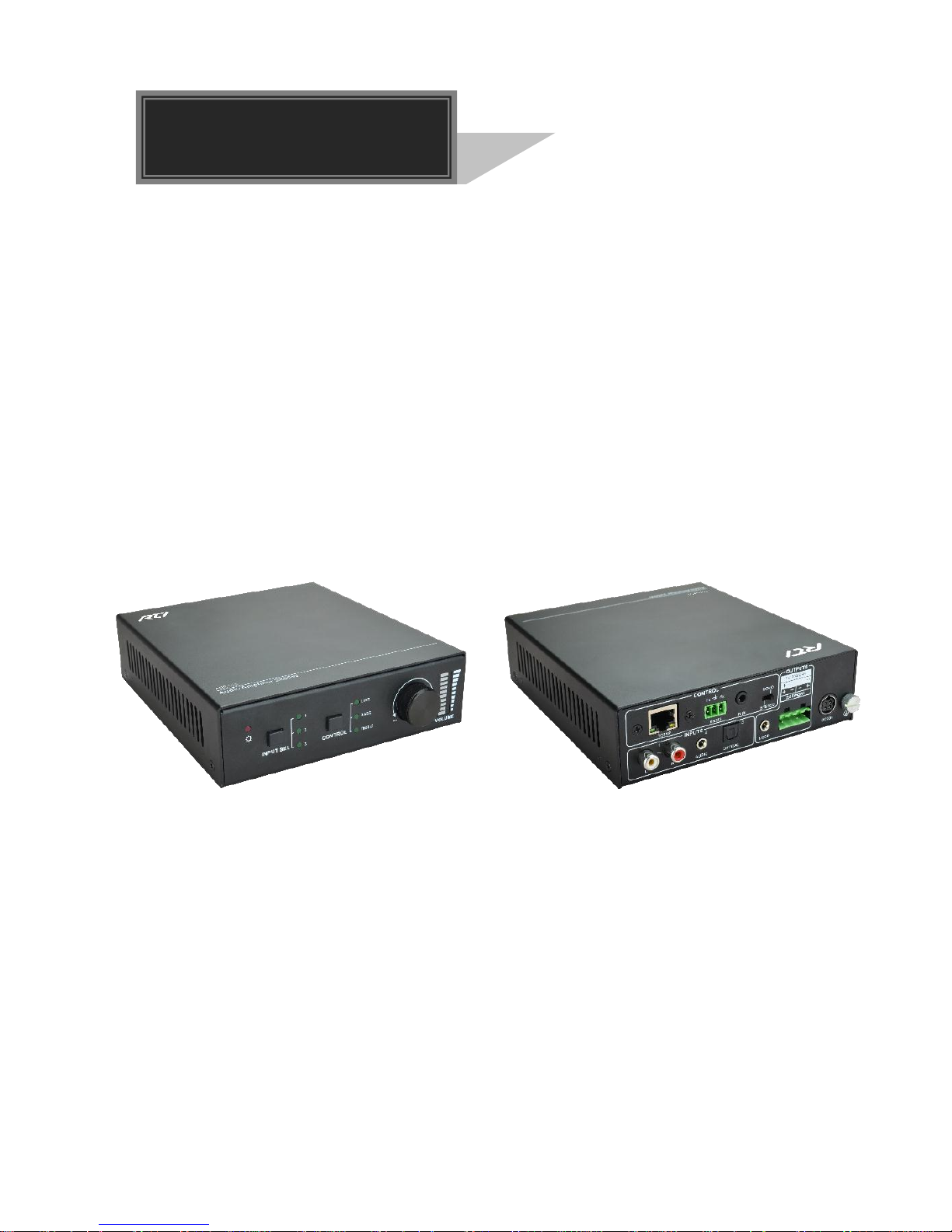
The AMR-350 is a compact-size digital amplifier (Class-D) with 3 inputs (1 L+R stereo
audio, 1 analog audio, 1 optical fiber audio). It features switchable stereo or mono
output, and boasts complete EQ adjustment and intuitive work status display, making it
an ideal addition to a classroom or conference room application.
1.2 Features
3 audio inputs: 1 L+R stereo, 1 analog, 1 optical fiber.
Switchable stereo / mono output.
Complete EQ management: including LINE, BASS and TREBLE.
Easy volume adjustment via a rotary knob.
Audio loop output.
Intuitive LED indicators for input source, control and volume setting.
Controllable via RS232, IR, TCP/IP (optional).
Web-based GUI.
Power off memory
1.3 Package List
1 x AMR-350
2 x Detachable Mounting Ears
4 x Screws
2 x Pluggable Terminal Blocks (1 3-pin& 1 4-pin)
1 x IR Remote
1 x Power Adapter (DC 36V 2.66A)
1 x User manual
1 x IR Receiver (5V, without carrier)
Please confirm if the product and the accessories are all included, if not, please
contact with the dealers.
Mini Audio Amplifier
2
2. Panel Description
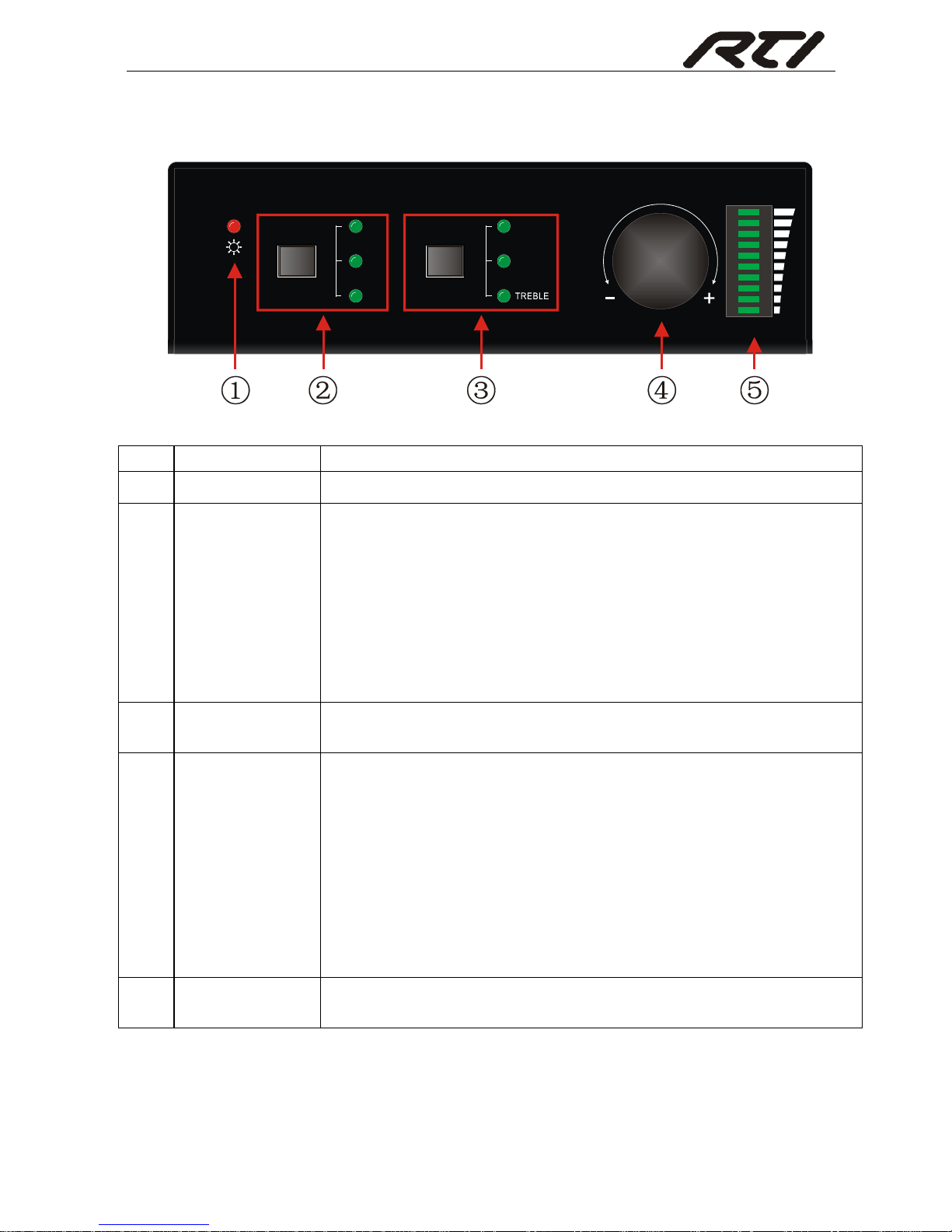
2.1 Front Panel
Figure 2- 1 Front Panel
No.
Name
Description
①
Power LED
Illuminates red when powered on.
②
Input Selection
Press to select any one of the 3 inputs, indicators will light
accordingly.
Input 1~3 corresponds to audio sources connected to the 3
audio input ports separately.
1: L+R stereo audio.
2: 3.5mm analog audio.
3: optical audio.
③
Control
Press to select the audio to be controlled, including LINE,
BASS and TREBLE.
④
Volume Knob
Press to mute/unmute the audio.
Note: after pressed the button to mute the audio, except
pressing it again to restore the audio at the same volume,
users can rotate the knob to enable audio output at
respective volume.
Rotate the knob to adjust volume, volume bars will change
accordingly
Clockwise Rotation: Volume up.
Anticlockwise Rotation: Volume down.
⑤
Volume Bars
Indicate real-time volume setting, 10 bars in total, no volume
bar will be lighted when the audio is muted.
Operation Format: “INPUT SEL” + “CONTROL” + “Volume Knob”
Example: To adjust bass audio of input 3, select input 3 -> choose bass -> adjust the
volume knob.
CONTROLINPUT SEL
1
2
3
LINE
BASS
VOLUME
Mini Audio Amplifier
3
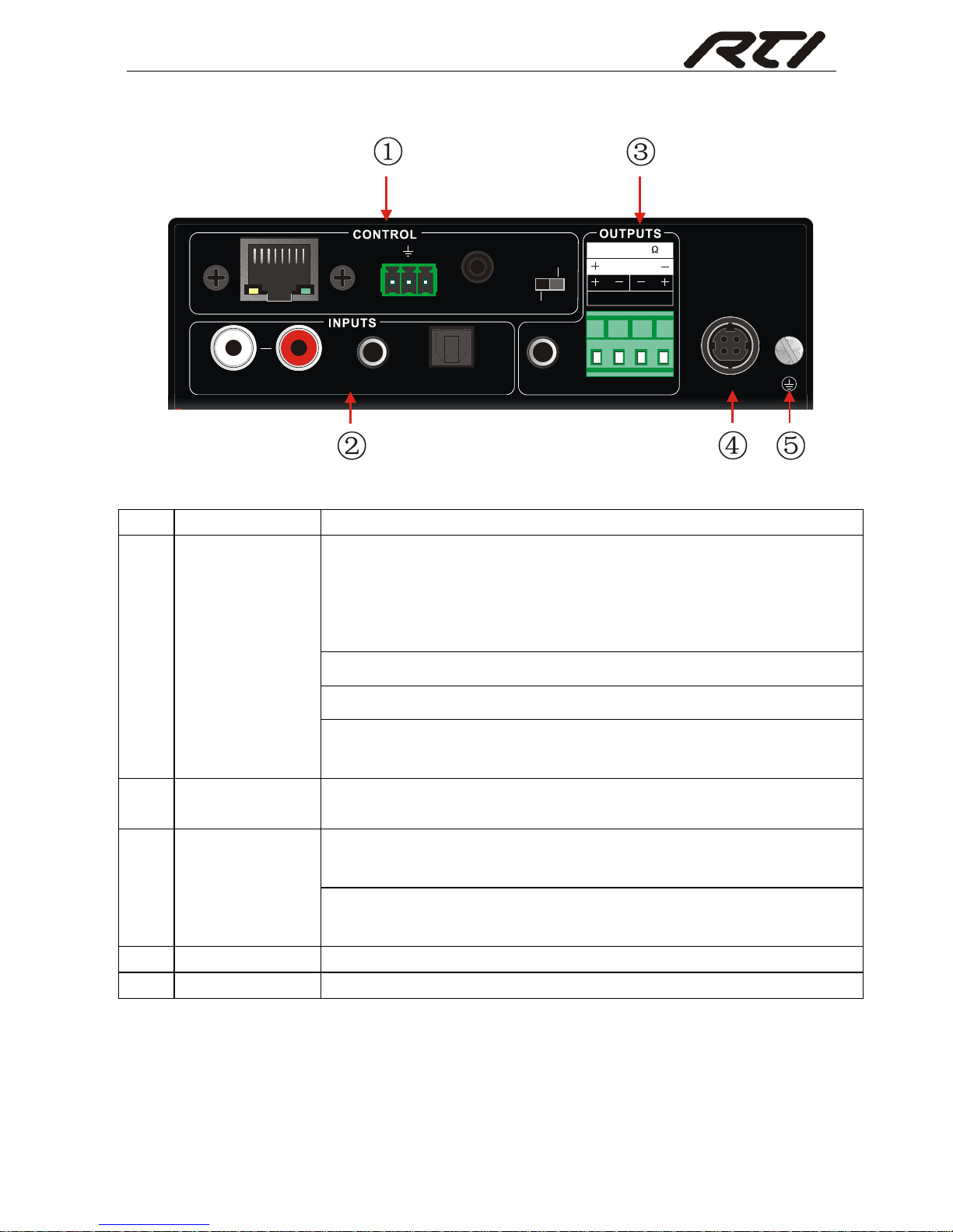
2.2 Rear Panel
Figure 2- 2 Rear Panel
No.
Name
Description
①
CONTROL
TCP/IP: (optional) Connect with control device to enable IP
control via web-based GUI& TCP/IP communication software;
Indicators will blink when connected to control device and
communicated normally.
RS232: Connect with control device to enable serial control.
IR IN: Connect with IR receiver to collect infrade signal.
Channel Switcher: Dial to STEREO or MONO to enable
corresponding output mode.
②
INPUTS
Audio inputs area, 3 audio inputs in total, including 1 stereo
audio, 1 analog audio and 1 optical audio.
③
OUTPUTS
LOOP: Analog audio loop output port, available only when
input signal is L+R stereo audio.
Audio Output: Including stereo audio (2x50W@8Ω), or mono
output (1x100W@4Ω).
④
DC 36V
Insert DC 36V 2.66A power adapter here.
⑤
GND
Connect to grounding.
Dial the Channel Switcher to demand status before connecting output device.
Once connected, do not try to change the status while it’s working.
LOOP
3
1
DC 36V
IR INRS232
Tx
Rx
AUDIO OPTICALL R
2
TCP/IP
2x50W 8@
Ω
1x100W 4 @
STEREO
MONO
Mini Audio Amplifier
4
3. System Connection
3.1 Usage Precaution
Verify all components and accessories included before installation.
System should be installed in a clean environment with proper temperature and
humidity.
All of the power switches, plugs, sockets and power cords should be insulated and
safe.
All devices should be connected before power on.
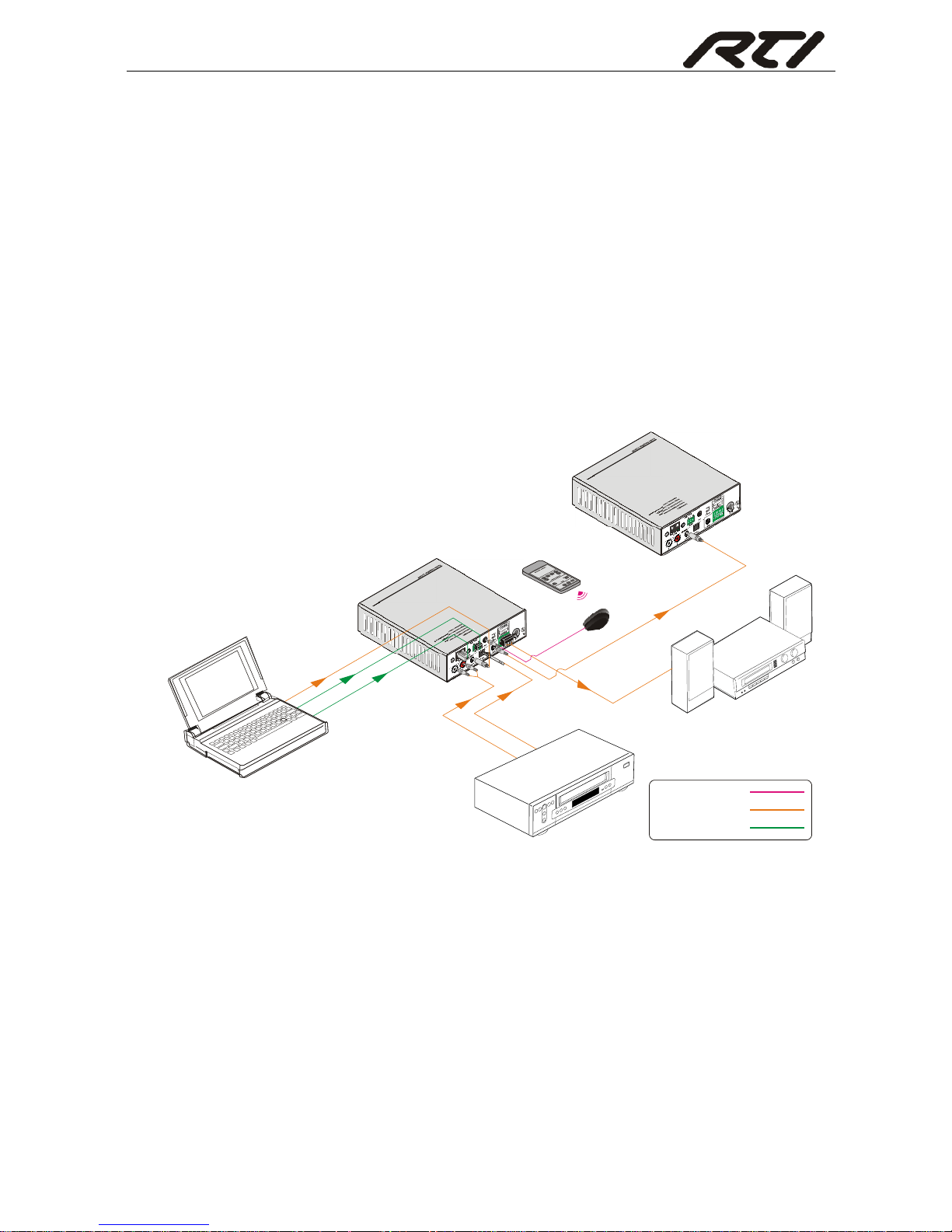
3.2 System Diagram
Figure 3- 1 System Diagram
3.3 Connection Procedure
Step1. Connect audio sources (such as Blue-ray DVD) to INPUT ports of the device with
audio cables;
Step2. Dial the Channel Switcher to the right status, and connect audio output devices
(such as speakers) to audio output port accordingly (Specified in 3.4 Audio
Output Connection).
Step3. (optional) Insert an IR receiver (5V, without carrier) to IR IN to enable IR control.
Laptop
Speaker
Audio Amplifier
IR Remote
IR Receiver
Audio Amplifier
IR Signal:
AUDIO Signal:
Control Signal:
DVD
Mini Audio Amplifier
5
Step4. (optional) Connect a control device (e.g. a PC) to RS232 port to enable serial
control.
Step5. (optional) Connect a control device (e.g. a PC) to TCP/IP port to enable IP
control.
Step6. Plug DC 36V power adaptor to the power port of AMR-350.
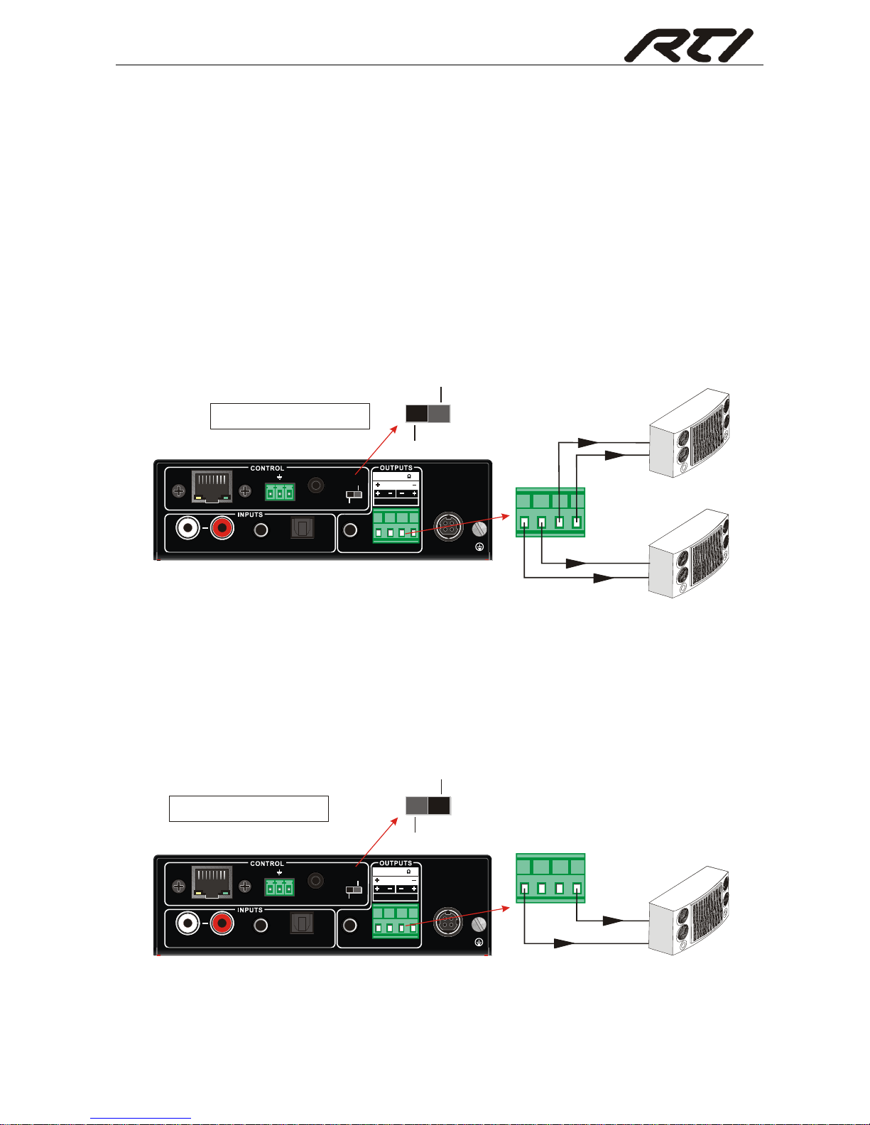
3.4 Audio Output Connection
3.4.1 Stereo Output (default): 2x50Watt@8Ohm
Dial the switcher to STEREO to enable 2 50Watt@8Ohm stereo output mode. Connect
the amplifier regularly (as shown in the following figure):
Figure 3- 2 Stereo Output Connection
3.4.2 Mono Output: 1x100Watt@4Ohm
To enable mono 1x100Watt@4Ohm output, dial the switcher to MONO, and connect
output devices as the figure below:
Figure 3- 3 Mono Output Connection
LOOP
3
1
DC 36V
IR INRS232
Tx
Rx
AUDI O OPTICALL R
2
TCP/ IP
2x50W 8@
Ω
1x100W 4 @
STER EO
MONO
Speaker
Speaker
Switch to "STEREO"
STEREO
MONO
LOOP
3
1
DC 36V
IR INRS2 32
Tx
Rx
AUDI O OPTICALL R
2
TCP/ IP
2x50 W 8@
Ω
1x10 0W 4 @
STER EO
MONO
Speaker
STEREO
MONO
Switch to "MONO"

Mini Audio Amplifier
6
3.5 Loop Connection
AMR-350 boasts a LOOP port for audio signal loop output, max 255 units can be looped
within the same operation system. Connect AMR-350 like this:
Figure 3- 4 Loop Connection
Then audio signal sent to the first AMR-350 is cascaded to other connected AMR-350,
which enables multiple AMR-350 share the same audio source.
Audio loop output is available only when the 1
st
AMR-350 select input 1/2 as source.
Audio control operations are not available to looped audio signal.
3.6 Application
AMR-350 has a good application in various occasions, such as computer realm,
monitoring, big screen displaying, meeting room, education and bank & securities
institution etc.
Laptop
Speaker
Audio Amplifier
Speaker
Speaker
Audio Amplifier

Mini Audio Amplifier
7
4. System Control
4.1 Front Panel Button Control
Front panel buttons provides direct audio control including input source selection and
audio effect adjustment.
Figure 4- 1 Front Panel Buttons
Operation Format: Input Sel + Control + Volume Knob (indicators and volume bar will
display real-time operation).
Input selection (area ①):
Press button INPUT SEL to switch among the 3 inputs cyclely, relative LED will
light to indicate real-time selection. There are 3 selectable audio sources,
corresponding to the 3 audio input ports on the rear panel separately.
1: L+R stereo audio
2: 3.5mm analog audio
3: optical audio
Control (EQ management) (area ②):
Including LINE, BASS and TREBLE, press button Control to switch among the 3
inputs circularly, relative LED will light to indicate real-time selection.
Volume Knob (area ③):
Clockwise Rotation: Volume up
Anticlockwise Rotation: Volume down
About the Volume Bar (area ④):
Volume bar indicates real-time volume setting, 10 bars in total, the higher the volume is,
the more bars will be illuminated. In different EQ control, volume bar tend to act
differently:
LINE: Line volume can be 0~60, one more volume bar will light when the volume is
turned up by 6.
BASS: bass volume can be 0~10
TREBLE: treble volume can be 0~10
CONTROLINPUT SEL
1
2
3
LINE
BASS
VOLUME

Mini Audio Amplifier
8
4.2 IR Control
Connect an IR receiver (5V, without carrier) to IR IN port on the rear panel, users are
able to control the amplifier by the included IR remote (see as below):
Figure 4- 2 IR Remote
Input Selection
Unmute
Mute
Volume Control
Including LINE, BASS
and TREBLE volume
adjustment

Mini Audio Amplifier
9
4.3 RS232 Control
AMR-350 boasts a 3-pin pluggable terminal block for serial control. The definition of
its pins is listed in the table below.
No.
Pin
Function
1
N/u
Unused
2
Tx
Transmit
3
Rx
Receive
4
N/u
Unused
5
Gnd
Ground
6
N/u
Unused
7
N/u
Unused
8
N/u
Unused
9
N/u
Unused
Connect AMR-350 to the control device (e.g. a PC) with RS232 cable and set the
parameters in the right manner, the control device is capable to control AMR-350 via
designed software.
4.3.1 RS232 Control Software
Installation: Copy the control software file to the computer connected with
AMR-350.
Uninstallation: Delete all the control software files in corresponding file path.
4.3.2 Basic Setting
Firstly, connect AMR-350 with an input device and an output device. Then, connect it
with a computer which is installed with RS232 control software. Double-click the
software icon to run this software.
Here we take the software CommWatch.exe as example. The icon is showed as below:

Mini Audio Amplifier
10
The interface of the control software is showed as below:
Please set the parameters of COM number, bound rate, data bit, stop bit and the parity
bit correctly, only then will you be able to send command in Command Sending Area.
Parameter Configuration area
Monitoring area, indicates
whether the command
sent works.
Command Sending area
Parameter Configuration area
Monitoring area, indicates
whether the command
sent works.
Command Sending area

Mini Audio Amplifier
11
4.3.3 RS232 Command
Case-sensitive.
“[“, “]” in the commands are only for easy recognition and not necessary in real
operations. Other symbols including “!” “#” are parts of the commands.
Feedbacks listed in the column “Feedback” are only for reference, feedbacks may
vary according to different operations.
Communication protocol: Baud rate: 9600; Data bit: 8; Stop bit: 1; Parity bit: none.
Command
Description
Feedback Example
#RST!
Factory reset.
@RST:OK!
#IPA?!
Report IP address of device.
@IPA:192.168.0.178!
#RAV:[XX]A01!
Route audio input [XX] to output 01.
[XX] =01 or 02 or 03.
@RAV:AUDIO 01 TO OUT
01!
#VOL:OUTMUTE!
Mute output audio (speaker).
@VOL:OUT MUTE!
#VOL:OUTUNMUTE!
Unmute output audio (speaker).
@VOL:OUT UNMUTE!
#VOL:OUTUP!
Volume up for output audio.
XX=00~60.
@VOL:OUT XX!
#VOL:OUTDN!
Volume down for output audio.
@VOL:OUT XX!
#VOL:OUT[XX]!
Set volume to [XX] for output audio.
XX=00~60.
@VOL:OUT XX!
#VOL:BASUP!
Volume up for output audio. XX=00~10.
@VOL:BAS XX!
#VOL:BASDN!
Volume down for output audio. XX=00~10.
@VOL:BAS XX!
#VOL:BAS[XX]!
Set volume to [XX] for output audio.
XX=00~10.
@VOL:BAS XX!
#VOL:TREUP!
Volume up for output audio. XX=00~10.
@VOL:TRE XX!
#VOL:TREDN!
Volume down for output audio. XX=00~10.
@VOL:TRE XX!
#VOL:TRE[XX]!
Set volume to [XX] for output audio.
XX=00~10.
@VOL:TRE XX!
#RPT:STATUS?!
Report system status.
@RAV:AUDIO 01 TO OUT
01!
@VOL:OUT UNMUTE!
@VOL:OUT 30!
@VOL:BAS 00!
@VOL:TRE 00!

Mini Audio Amplifier
12
4.4 TCP/IP Control
AMR-350 boasts option TCP/IP port for IP control.
Default settings: IP: 192.168.0.178; Subnet Mast: 255.255.255.0; Gateway: 192.168.0.1;
Serial Port: 4001.
IP& gateway can be changed as you need, Serial Port cannot be changed.
Connect the Ethernet port of control device and TCP/IP port of AMR-350, and set same
network segment for the 2 devices, users are able to control the device via web-based
GUI or designed TCP/IP communication software.
4.4.1 Control Mode
The AMR-350 can be controlled by PC without Ethernet access or PC(s) within a LAN.
Controlled by PC without Ethernet access
Connect a computer to the TCP/IP port of the AMR-350, and set its network segment to
the same as the AMR-350’s.
Same network
segment as the
switcher

Mini Audio Amplifier
13
Controlled by PC(s) in LAN
Connect AMR-350, a router and several PCs to setup a LAN (as shown in the following
figure). Set the network segment of AMR-350 to the same as the router’s, then PCs
within the LAN are able to control AMR-350.
Follow these steps to connect the devices:
Step1. Connect the TCP/IP port of the AMR-350 to Ethernet port of PC with straight-thru
CAT5e/6.
Step2. Set the PC’s network segment to the same as the AMR-350’s.
Step3. Set the AMR-350’s network segment to the same as the router.
Step4. Set the PC’s network segment to the original ones.
Step5. Connect the AMR-350 and PC(s) to the router. PC(s) within the LAN is able to
control the AMR-350 asynchronously.

Mini Audio Amplifier
14
4.4.2 Control via TCP/IP Communication Software
(Exampled by TCPUDP software)
1) Connect a computer and AMR-350 to the same network. Open the TCPUDP
software (or any other TCP/IP communication software) and create a connection,
enter the IP address and port of AMR-350 (default IP: 192.168.0.178, port:4001):
2) After connect successfully, we can enter commands to control the AMR-350, as
below:
Here you will receive the
feedback when a command
is sent.
Enter your command here.
Commands are the same with
RS232 commands listed in 4.3.3
RS232 Communication

Mini Audio Amplifier
15
4.4.3 Control via Web-based GUI
AMR-350 provides with built-in GUI for convenient TCP/IP control. GUI allows users to
interact with AMR-350 through graphical icons and visual indicators.
Type 192.168.0.178 (default IP, changeable via GUI) in your browser, it will enter the
log-in interface shown as below:
Figure 4- 3 Log-in interface
GUI interfaces can be displayed in Chinese/ English, selectable by clicking 中文/
ENGLISH.
Type the right name and password in relative column:
Name: admin; Password: admin (default setting, changeable via GUI)
Click LOGIN, it will show the audio selection interface as shown below:
Audio Selection:
Figure 4- 4 Network Control

Mini Audio Amplifier
16
In this interface, you can:
Select input
Mute/ Unmute
LINE/ BASS/ TREBLE control: drag the volume dot to turn down/ up the
corresponding volume
Switch to network configuration interface by clicking NETWORK
Network Configuration:
Figure 4- 5 Audio Selection
In this interface, you can:
Configure network settings:
IP: support DHCP and Static IP, choose demanded state by clicking the button.
DHCP: IP Address, subnet mask and gateway are fixed in this mode.
Static IP: set IP Address, subnet mask and gateway manually. Make sure the IP is
different with control device’s.
Modify password: type in new password in the column, max at 5 numbers/ letters.
Inquire software version.
Switch to audio selection interface by clicking AUDIO SEL.
If there is any modification in this interface, press Save to restore the settings, or press
Cancel to withdraw. Click ADUIO SEL to return to NETWORK interface.
Clear the cache of the browser beforehand to ensure reliable GUI operation.

Mini Audio Amplifier
17
4.4.4 Port Management
Type the designed website 192.168.0.178:100 (Default, changeable via GUI) in your
browser. Enter correct username and password (same with GUI name and password) to
log in the WebServer:
Here is the main configuration interface of the WebServer:
In this interface, you can:
Change website display language
Modify network settings: Go to Internet Settings -> WAN
Upgrade TCP/IP module: Go to Administration -> Upload Program -> Select
program file -> Start upgrading
Reboot the device after upgrading.

Mini Audio Amplifier
18
5. Specification
Input
Input Signal
1 x L+R stereo audio; 1x 3.5mm analog audio;
1 x Optical Fiber audio
Connectors
2 x RCA; 1x 3.5mm TRS plug;1x SPDIF
Input impedance
>10KΩ
Output
Output Signal
1 x LOOP; 2 x Stereo audio/1 Mono audio;
Connectors
1 x 3.5mm jack;1 x 4-pin 5.08mm connector
Damping coefficient
>100
Control
Control Ports
1 x RS232 (3-pin pluggable terminal block);
1 x IR IN (3.5mm female); 1 x TCP/IP (RJ45 female, optional)
Panel Control
Front panel buttons& rear panel switcher
General
SNR
80dB
THD+ Noise
1%@1KHz 50W
Separation
75dB 20Hz~20KHz
Damping coefficient
100
Voltage Gain
32dB
Power Supply
DC 36V 2.66A
Power Consumption
1.48W
Work Temperature
0~50℃
Relative Humility
10%~90%
Dimensions (W*H*D)
148 mm x 44 mm x 165 mm
Net Weight
720g
Note: All nominal levels are at ±10%.

Mini Audio Amplifier
19
6. Panel Drawing
Audio Amplifier 2x50W
AMR-350
CONTR OLINPUT S EL
1
2
3
LINE
BASS
VOLUM E
LOOP
3
1
DC 36V
IR INRS232
Tx
Rx
AUDIO OPTICA LL R
2
TCP/IP
2x50W 8@
Ω
1x100W 4 @
STEREO
MONO
148 mm
1
6
5
m
m
4
4
m
m
11
7
m
m

Mini Audio Amplifier
20
7. Troubleshooting & Maintenance
Problem
Potential Cause
Solution
No output audio
Loose or broken connection at
input/ output end.
Reconnect the devices.
No connected source at the
chosen input channel.
Insert source to the port or
change for other input
channels.
Audio has been muted.
Press the volume knob to
unmute.
Wrong output connection.
Connect output according to
different transmission mode
(stereo or mono).
Power indicator is
off and the device
respond nothing to
any operation
Not energized yet.
Energize the device.
Loose or broken power
connection.
Reconnect the power adapter.
Fail in TCP/IP
control
Control device and AMR-350
are on different network
segment.
Set the network segment of
control device to the same with
AMR-350’s.
Network segment of AMR-350
is different with LAN’s.
Set the network segment of
AMR-350 to the same with
LAN’s.
Fail in RS232
control
Loose or broken RS232
connection.
Reconnect the devices or
change for another RS232
cable.
Wrong command.
Send the exact command
listed in 4.3.3.
Wrong communication
protocol.
Set the protocol to: Baud rate:
9600; Data bit: 8; Stop bit: 1;
Parity bit: none.
Fail in IR control
Run out of battery.
Change for new batteries.
Exceed effective control
distance or angle.
Adjust control distance and
angle.
No loop output
No connected source at input 1
& 2 of the 1st AMR-350.
Connect audio source to input
1 or 2 of the 1st AMR-350.
Wrong input selection at the 1st
AMR-350.
Select input 1/2 at the 1st
AMR-350.
If your problem persists after following the above troubleshooting steps, seek further
help from authorized dealer or our technical support.

Mini Audio Amplifier
21
8. Customer Service
The return of a product to our Customer Service implies the full agreement of the terms
and conditions hereinafter. There terms and conditions may be changed without prior
notice.
1) Warranty
The limited warranty period of the product is fixed 3 (three) years.
2) Scope
These terms and conditions of Customer Service apply to the customer service
provided for the products or any other items sold by authorized distributor only.
3) Warranty Exclusions:
Warranty expiration.
Factory applied serial number has been altered or removed from the product.
Damage, deterioration or malfunction caused by:
Normal wear and tear.
Use of supplies or parts not meeting our specifications.
No certificate or invoice as the proof of warranty.
The product model showed on the warranty card does not match with the
model of the product for repairing or had been altered.
Damage caused by force majeure.
Servicing not authorized by distributor.
Any other causes which does not relate to a product defect.
Shipping fees, installation or labor charges for installation or setup of the product.
4) Documentation:
Customer Service will accept defective product(s) in the scope of warranty coverage
at the sole condition that the defeat has been clearly defined, and upon reception of
the documents or copy of invoice, indicating the date of purchase, the type of
product, the serial number, and the name of distributor.
Remarks: For further assistance or solutions, please contact your local distributor.


Remote Technologies Incorporated
5775 12th Avenue East, Suite 180
Shakopee, MN 55379
Tel: 952-253-3100
Fax: 952-253-3131
www.rticorp.com
 Loading...