


1
www.r-techwelding.co.uk
Tel: 01452 733933 : Fax 01452 733939
PLASMA 50CNC
INVERTER PLASMA CUTTER
OPERATION INSTRUCTI ONS
Version 2016-1

2

3
Thank you for selecting the R-Tech PLASMA 50CNC Inverter Plasma Cutter
The PLASMA 50CNC has many benefits over traditional transformer plasma cutters, including infinite power
control, Pilot arc starting and quick fitting cost effective torch, long life cost effective torch consumables, 60%
industrial duty cycle and CNC interface to connect to CNC Plasma System.
We want you to take pride in operating our PLASMA 50CNC as much pride as we have taken in making this
product for you. Please read all information in this manual before operation
PLEASE EXAMINE CARTON AND EQUIPMENT FOR DAMAGE IMMEDIATELY
When this equipment is shipped, title passes to the purchaser upon receipt from the courier. Consequently all claims for
material damaged in shipment must be made by purchaser against the transportation company used. Please record your
equipment identification below for future reference. This information can be found on data plate at rear of machine.
Product PLASMA 50CNC
Serial No. ___________________________________
Date of Purchase _____________________________
Where Purchased _____________________________
Whenever you request replacement parts or information on this equipment please always supply information you have
recorded above
This product is covered by 2 years collect and return UK warranty, R-Tech will cover cost of collection, repair and return of
item to UK mainland (other areas are RTB). External items, torch, earth lead etc are covered by 3 months warranty. Any
faults/damage found caused by customer will be charged pro-rata.
Pay particular attention to the safety instructions we have provided you for your protection. The level of
seriousness to be applied to each section is explained below
WARNING
This statement appears where the information must be followed exactly to avoid serious personal injury.
CAUTION
This statement appears where the information must be following to avoid a minor personal injury or damage to this
equipment.

4
Introduction
The R-Tech PLASMA 50CNC is a member of our field acclaimed family of welding products. Premium
features include:
1. Inverter power source - more efficient to operate, provides smoother weld characteristics.
2. CNC Interface giving Start, Arc Success & voltage reading for THC systems
3. NON-HF Pilot Arc starting – No local interference compared to HF start machines
4. Pilot arc restart - ideal for cutting mesh etc
5. Digital amp meter
6. Quick fitting torch for easy torch fitment/replacement
7. Long life -Low cost torch consumables
8. 60% Duty cycle at 50 Amps @ 40
O
C
Recommended Processes
The R-Tech PLASMA 50CNC is recommended for the plasma cutting processes within its output capacity of
50 Amps DC
Equipment Limitations
The R-Tech PLASMA 50CNC is protected from overloads beyond the output ratings and duty cycle as per machine
specifications with thermostat protection of the output coils and rectifiers and is rated at 50 Amps at 60% duty cycle
on a ten minute basis. If the duty cycle is exceeded a thermal protector will shut machine off until the machine cools.
Technical Specifications
Model R-Tech P50CNC
Input Power 220 / 240V 50/60Hz
Fuse rating
32 Amps
Rated output current
50 Amps
Current adjustment range
20 – 50 Amps
No load voltage
200V
Duty cycle @ 40c
60 %
Starting Mode
Pilot Arc – Cartridge start NON HF
Air pressure
70 PSI
Max Cutting Thickness – Hand Torch – Clean Cut – Mild Steel
18mm
Max Cutting Thickness – Hand Torch – Severance Cut – Mild Steel
24mm
Max Cutting Thickness – Machine Torch Piercing – Clean Cut – Mild Steel
12mm
Air post flow
- 25s
Dimensions
390 x 190 x 290
Weight
18KG

5
Safety Precautions
Read entire section before starting install ati on
WARNING!
Electric Shock can kill. Only qualified personnel should perform this installation. Turn off input power at the fuse box
before working on this equipment. Do not touch electrically live parts. Always connect the machine to an earthed
mains supply as per national recommended standards.
Select suitable location
Place the plasma cutter where clean cooling air can freely circulate in and out of the front & rear louver vents. Dirt, dust or
any foreign material that can be drawn through vents into plasma cutter must be kept to a minimum. Failure to observe
these precautions can result in excessive operating temperatures which can lead to plant failure.
Grinding
Do not direct grinding particles towards the plasma cutter. An abundance of conductive material can cause plant failure.
Transport Unloading
Never underestimate the weight of equipment, never move or leave suspended in the air above people. Use
recommended lifting equipment at all times.
WARNING!
Falling Equipment can cause injury. Never lift plasma cutter with gas bottle attached. Never lift above personnel.
Tilting
Machine must be placed on a secure level surface or on a recommended undercarriage/trolley. This machine may topple
over if this procedure is not followed.
Environmental Rating
The plasma power source carries the IP21S rating. It may be used in normal industrial and commercial environments.
Avoid using in areas where water / rain is around.

6
Electrical Installation
WARNING!
ELECTRIC SHOCK CAN KILL
Machine grounding and High Frequency Interference Protection
This plasma cutter must be grounded to earth. See national electrical codes for proper grounding methods. The high
frequency generator being similar to a radio transmitter may cause interference to radio, TV and other electronic
equipment. These problems may be the result of radiated interference. Proper grounding methods can reduce or eliminate
this. Radiated interference can develop in the following ways
1. Direct interference from welder power source
2. Direct interference from the welding leads
3. Direct interference radiated from feedback into power lines
4. Interference from re-radiation by un-ground ed meta lli c obj ects .
Keeping these contributing factors in mind, installing equipment as per following instructions should minimize
problems.
1. Keep the welder input power lines as short as possible and enclose as much of them as possible in metal
conduit or equivalent shielding. There should be a good electrical contact between this conduit and ground
(Earth).
2. Keep the work and electrode leads as short as possible. Tape the leads together where practical.
3. Be sure the torch and earth leads rubber coverings are free from cuts and cracks that allow welding power
leakage
4. Keep earth lead connection to work in good condition, clean area on workbench where earth clamp is situated
on a regular basis.
Input Connections
Make sure the voltage, phase and frequency of input power is as specified on machine rating plate located at rear of
machine.
Have a qualified electrician provide suitable input power as per national electrical codes. Make sure machine is earthed /
grounded.
Make sure fuse or circuit breaker is correct rating for machine. Using fuses or circuit breakers smaller than recommended
will result in nuisance shut off from welder inrush currents even if cutting at low amperages. Failure to follow these
instructions can cause immediate failure within the welder and void machines warranty.
Turn the input power OFF at the mains switch & fuse box before working on this equipment. Have a qualified electrician
install & service this equipment. Allow machine to sit for 5 minutes minimum to allow the power capacitors to discharge
before working inside this equipment. Do not touch electrically live parts

7
The PLASMA 50CNC Plasma Cutters require a 240V 50/60Hz 1-Phase supply. It requires a 32A fused supply. It comes
with a mains cable attached. Connect wires according to national coding.
Brown wire Live
Blue wire Neutral
Green/Yellow Wire Earth (Ground)
Connecting to a mains electrical supply
THIS MACHINE IS OF AN INDUSTRIAL SPECIFI CATION AND MUST BEFITTED TO A
32AMP 240V MAINS INPUT - DO NOT RUN ON 13AMP PLUG – FAILURE TO RUN ON
CORRECT SUPPLY WILL IN-VALIDATE WARRANTY
Connecting to an Engine Driven Generator
If connecting this Plasma Cut t er to an engine driven generator please ensure the
following
Minimum Generator KVA Output 12KVA continuous
Generator to be fitted w ith AVR (automatic voltage regul ation)
DO NOT USE ON A GENERATOR WITHOUT AVR
Connecting to a generator without the above minimum requirements will
invalidate your warranty.

8
Connections for PLASMA 50CNC
Rear Machine connections
Fig 1
1. Air pressure regulatin g kn ob
This regulates the air pressure as displayed in gauge on front of machine. To adjust pressure pull knob upwards and
turn to adjust pressure, once correct pressure is obtained press down knob to secure.
2. Air pressure input
Screw supplied PCL fitting into regulator ensuring no air leaks. You can also fit other connectors to suit your needs
3. Earth connection
This can be used to earth the machine to workbench if you are experiencing interference - Not normally used
4. Mains input cable
Fit required plug as per your electrical installation
9
5. POWER On/Off Switch
Turns machine on and off, the switch illuminates when machine turn on
6. CNC Interface
This is the socket where the CNC cable is connected. (Plug is supplied with machine)
CNC Interface connections
PINS
Start cut
1 & 2 – close circuit to start
OCV Positive (default 50/1 divided)
6
OCV Negative (default 50/1 divided)
4
Arc sucess – OK to move
9 & 10 – closed when arc OK
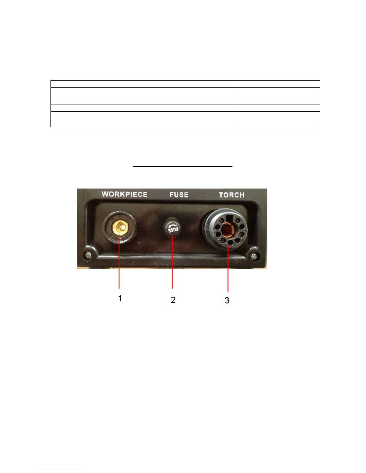
Front machine connections
Fig 2
1. Earth / Work piece connector
Connect the earth lead to this connector. Insert male connector into socket and twist clockwise until tight.
Secure other end of earth lead to work piece via the earth clamp.
2. FUSE
30A Pilot arc fuse – Protects in case of short circuit in torch head
3. Torch power connector
Connect the main torch euro socket by locating and pushing in and the screw retainer clockwise until tight.
When fitting CNC machine to holder, do not overtighten clamp onto torch housing as this can affect pilot arc
starting

10
Controls and Settings
Fig 1
1. Air pressure gauge
This shows the air pressure as set by regulator at rear of machine. This should be set to 70PSI when the test
gas button is activated.
2. Amperage control knob
This adjusts the amperage (cutting power) from 20 to 50 amps
3. L.E.D amperage display
When cutting this shows the actual cutting amperage
4. Test Gas / Cutting selector switch
When in the up position this is test gas mode, when setting air pressure switch to test gas so you obtain actual
air flow cutting pressure When in the down position this is cutting mode, you can now
start cutting
5. Auto / Standard switch
When in the down position this is in standard cutting mode, this is the normal operating position for plasma
cutting with a hand held and machine type torch, when in the up position this is in auto mode (4T) this is for
special applications when using automated machinery.
6. Indication of too low air pressure
The led will not be shown when the air pressure is less than 26psi and the machine will not work. Adjust
pressure to correct 70PSI, led will light and you can resume cutting.

11
Operating machine
SAFETY PRECAUTIONS
WARNING!
ELECTRIC SHOCK CAN KILL
Do not touch electrically live parts or electrode with skin or wet clothing.
Insulate yourself from work and ground
Always wear dry insulating gloves
WARNING!
FUMES AND GASES can be dangerous
Keep your head out of fumes & gases produced from welding. Use ventilation or exhaust to remove fumes &
gases from breathing zone and general area.
WARNING!
WELDING SPARKS can cause fire or explosion
Keep flammable material away from work area. Do not weld on containers that have held combustibles
WARNING!
ARC RAYS can burn
Wear eye, ear and body p rotection M ake s u re work area is protected by proper shi eld ing to av oi d injury to passers
by.

12
Operating Machine – Hand Torch
Please ensure all torch consumables are tight before use
1. Ensure machine has been setup as previously stated
2. Turn on the machine and the power light indicates and cooling fan is running
3. Set the function switch in the test gas position, air will flow from torch head, now set the air pressure in
gauge using adjuster on regulator on rear of machine to 70PSI, Once the correct air pressure has been set
press down the adjuster on air regulator and set the function switch to the cutting position
4. Ensure earth clamp is connected to work piece or workbench ensuring a good clean point of contact
5. Select cutting amperage knob to desired cutting power (the following guide lines will vary in accordance to
material grade, characteristics and user operation)
a. 20 Amps for up to 6mm clean cut on mild steel
b. 30 Amps for up to 9mm clean cut on mild steel
c. 50 Amps for up to 18mm clean cut on mild steel, when cutting aluminium, alloys and stainless steel
cutting thickness is reduced by approximately 20%
6. Hold torch in starting position on work and press torch switch and the high frequency will initiate the pilot
arc and contact with the work piece and machine will automatically switch to main cutting power. Once you
come to the end of cut on work piece the machine will sense this and turn off main cutting power and pilot
arc will re-engage, to stop cutting release switch.
7. Getting correct amperage / cutting speed for desired job.
8. The combination of correct cutting amperage and travel speed can change per user; here are some tips on
obtaining optimum settings.
9. Blow back when cutting, If you experience blow back and the metal is not cut all the way through, you
either are traveling too fast or you need to increase the cutting amperage
10. Cutting arc is erratic and work is being cut all way through. You are traveling too slow or cutting with too
high amperage for work.
11. It can take a while to get used to plasma cutting if never done before. Experiment with settings on some
scrap material until you find the best amperage / cutting speed for user.
12. If you ever have any questions on settings call us and speak to one of our experienced technicians who will
be happy to help you.
13
Operating Machine – Machine Torch CNC
Please ensure all torch consumables are tight before use
1. Ensure machine has been setup as previously stated
2. Turn on the machine and the power light indicates and cooling fan is running
3. Set the function switch in the test gas position, air will flow from torch head, now set the air pressure in
gauge using adjuster on regulator on rear of machine to 70PSI, Once the correct air pressure has been set
press down the adjuster on air regulator and set the function switch to the cutting position
4. Ensure earth clamp is connected to work piece or workbench ensuring a good clean point of contact
5. Select cutting amperage knob to desired cutting power (the following guide lines will vary in accordance to
material grade, characteristics and user operation)
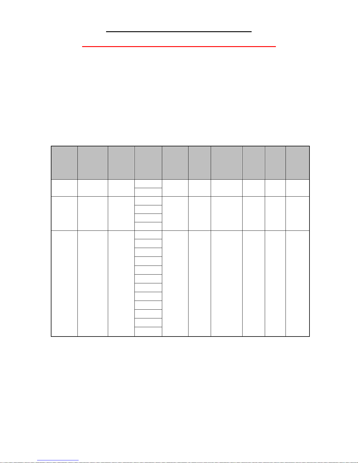
Plasma
Current
(amps)
Material
Thickness
(mm)
AVHC10
Pierce
Delay
Seconds
Plasma
Test Gas
Air
Pressure
Mach-3
THC
Feed
Rate
Pierce
Height
SheetCam
Pierce
Delay
Cut
Height
Best
Feed
Rate
Fastest
Feed
Rate
30
1
0.2
70 PSI
20%
3.5
0.0
1.7
1320
2430 2 0.2
70 PSI
20%
3.5
0.0
1.7
1140
2070
40
3
0.2
70 PSI
20%
3.5
0.0
1.7
1760
3240
4
0.3
70 PSI
30%
3.5
0.1
1.7
1310
1310 5 0.3
70 PSI
30%
3.5
0.2
1.7
1120
1120 6 0.3
70 PSI
30%
3.5
0.2
1.7
940
940
50
1
0.2
70 PSI
20%
3.5
0.0
1.7
2200
4050
2
0.2
70 PSI
20%
3.5
0.0
1.7
1900
3450
3
0.2
70 PSI
20%
3.5
0.0
1.7
1650
2850
4
0.3
70 PSI
30%
3.5
0.1
1.7
1400
2350
5
0.3
70 PSI
30%
3.5
0.2
1.7
1200
1900
6
0.3
70 PSI
30%
3.5
0.2
1.7
980
1500
7
0.4
70 PSI
30%
3.5
0.3
1.7
800
1150
8
0.4
70 PSI
30%
3.5
0.4
1.7
650
870
9
0.4
70 PSI
30%
3.5
0.5
1.7
520
640
10
0.5
70 PSI
30%
3.5
0.6
1.7
410
470
11
0.5
70 PSI
30%
3.5
0.7
1.7
320
365
12 0.6 70 PSI 30% 3.5 0.8 1.7
255
310
When cutting aluminum, alloys and stainless steel cutting thickness is reduced by approximately 20%
Common question: Why is cut depth reduced when cutting with CNC when compared to hand cutting?
Hand cutting you generally start from edge of work, when CNC cutting you normally start with a pierce
so this is why maximum cut depth is reduced.
6. Once above amperage is set and parameters are set on CNC system you are ready to start cutting.
7. Getting correct amperage / cutting speed for desired job.
8. The combination of correct cutting amperage and travel speed can change per user; here are some tips on
obtaining optimum settings.

14
9. Blow back when cutting, If you experience blow back and the metal is not cut all the way through, you
either are traveling too fast or you need to increase the cutting amperage
10. Cutting arc is erratic and work is being cut all way through. You are traveling too slow or cutting with too
high amperage for work.
11. It can take a while to get used to plasma cutting if never done before. Experiment with settings on some
scrap material until you find the best amperage / cutting speed.
12. If you ever have any questions on settings call us and speak to one of our experienced technicians who will
be happy to help you on 01452 733933

15
Replacing torch consumables
WARNING!
ELECTRIC SHOCK CAN KILL
Please ensure machine is turned off before changing con sumables
If cutting performance is po or you probably need to check / change t he torch con sumables. T o change the pl asma
cutting consumables carry out the follow ing proc edure
1. Switch off machine
2. Ensure torch has cooled down to avoid burns
3. Unscrew the retaining nozzle
4. Remove the cutting tip
5. Check the condition of cutting electrode, replace cutting electrode if tip is worn 1-2 mm and end is concave
6. Fit new cutting tip if required if cutting hole is distorted or an angled cut happens replace the cutting tip
7. It is normally good practice to replace electrode and cutting tip as a pair
8. Check condition of brown baker lite swirl ring, if signs of pitting / burning replace item
9. Refit retaining nozzle by screwing on hand tight
10. Turn machine back on and continue cutting

16
Maintenance
Routine and periodic maintenance
WARNING!
ELECTRIC SHOCK CAN KILL
Turn the input power OFF at the mains switch & fuse box and remove mains plug from socket before working
on this equipment.
Have a qualified electrician install & service this Plasma cutting equipment. Allow machine to sit for 5 minutes
minimum after disconnection from mains power to allow the power capacitors to discharge before working inside
this equipment.
Do not touch electrically live parts
1. Periodically (3-6 months depending on use / environment), remove the side/top panels of machine and
clean out machine with a low pressure dry air line paying particular attention to PC Boards, Fan blades and
switchgear
2. Failure to maintain plant can void manufacturer’s warranty.
3. Inspect input and output cables & hoses for fraying and cuts, replace if damaged present
4. Keep cutting torch and earth cables in good condition
5. Clean air vents to ensure proper air flow and cooling
6. The fan motor has sealed bearings which requires no maintenance

17
Fault Diagnostics
1. Power light not lit
Check machine on/off switch is in the on position, Check Input power to machine, Check plug wiring, Check
mains trip / fuses.
2. No output - Fan runs - Power light is lit
Check torch connections are secure and torch switch operation, try replacing plasma cutting torch
3. No output - Power light is lit - Warning light is lit
Welding application may have exceeded recommended duty cycle, allow machine to cool down until the
warning light goes out.
4. No output– Power light is lit– Air at torch tip– No Pilot Arc
Check condition of torch consumables and replace if worn
Check pilot arc protecting fuse on front panel of machine and replace if blow – If fuse keeps blowing contact
R-Tech for repair / replacement torch
Please ensure machine is switched off before checking fuses
Check for water in water trap at rear of machine, if water is present, drain air compressor, clean water out of air
lines, empty water trap by pressing water release button on bottom of air regulator water trap. Fit new
consumables as per instructions earlier in this manual
5. Machine keeps overheating - Warning light is lit on machine
Check if fan is running if not contact R-Tech for repair
Check the cooling vents for obstruction; blow out machine with clean dry low pressure air supply.
Check for adequate ventilation around machine
6. Erratic cutting - Torch spitting when cutting
Check torch consumables and replace if necessary as per instructions earlier in this manual
Check if correct amperage for thickness of metal, if travel speed is too slow or too much cutting power, increase
speed of cut or reduce cutting amperage. (When machine senses no metal left to cut it will switch of main
cutting power and switch on pilot arc, this is the pilot arc restart)
Water contamination in torch head, check for water in water trap at rear of machine, if water is present, drain air
compressor, clean water out of air lines and empty water trap by pressing water release button on bottom of air
regulator water trap. Fit new torch consumables as per instructions earlier in this manual

18
Plasma Torch Consumab les parts list
Model R-Tech P50CNC Torch Spares
Electrode
RT-PT100-52556
Cutting Tip 1.0mm
RT-PT100-51246.10
Retaining Nozzle
RT-PT100-60500
Double Pointed Spacer
RT-PT100-60444
Swirl Ring
RT-PT100-60025
O-Ring
RT-PT100-51190.41
Torch Head – Machine Type
RT-PT100-09710
Complete 6M Machine Torch
RT-P100CNC-6MMT
Complete 6M Hand Torch
RT-PT100-09721LG
You can order spares from our website here
Or call our sales department on 01452 733933

19

20
 Loading...