

Page 1

BEC 7300N
(802.11n) draft ADSL2+ Firewall Router
User Manual
Page 2

2
Table of Contents
Chapter 1 ............................................................................................... 4
1.1 Introduc ing the BEC 7300N ............................................... 4
1.2 Features .............................................................................. 6
1.3 Applications of the BEC 7300N .......................................... 9
Chapter 2 ............................................................................................. 10
2.1 Important Notes ................................................................ 11
2.2 Package Contents ............................................................. 11
2.3 The Front LEDs ................................................................. 12
2.4 The Rear Ports .................................................................. 13
2.5 Cabling .............................................................................. 14
Chapter 3 ............................................................................................. 15
3.1 Before Configuration ........................................................ 16
3.2 Factory Default Settings................................................... 20
3.3 LAN and WAN Port Addresses ........................................ 21
3.4 Information from your IS P ................................................ 22
3.5 Configuring with your BEC 7300N ................................... 22
Chapter 4 ............................................................................................. 27
4.1 Status ................................................................................. 28
4.2 Quick Start ........................................................................ 29
4.3 WAN ................................................................................... 30
4.4 WLAN ................................................................................. 31
Chapter 5 ............................................................................................. 34
5.1 Status ................................................................................. 35
5.1.1 ADSL St atus ................................................................... 37
5.1.2 ARP Table ....................................................................... 38
5.1.3 DHCP Table .................................................................... 38
5.1.4 System Log .................................................................... 39
5.1.5 Firewall Log .................................................................... 39
5.1.6 UPnP Portmap ............................................................... 40
5.2 Quick Start ........................................................................ 41
5.3 Configuration .................................................................... 46
5.3.1 LAN (Local Area Network) ............................................. 46
5.3.2 WAN (Wide Area Network) ............................................. 63
5.3.3 System ............................................................................ 73
5.3.4 Firewall ........................................................................... 78
5.3.5 QoS (Quality of Service) ................................................ 88
5.3.6 Virtual Server ................................................................. 94
5.3.7 Time Schedule ............................................................... 98
5.3.8 Advanced ..................................................................... 100
5.4 Save Configuration t o Fla s h ...........................................114
Page 3

3
5.5 Restart ..............................................................................114
5.6 Logout ..............................................................................115
Chapter 6 ............................................................................................116
Page 4

4
Chapter 1
Introduction
1.1 I nt roducing the BEC 7300N
Thank you for purchasing the BEC 7300N Router. Your new router is an all-in-one unit that
combines an ADSL modem, ADSL2/2+ router and Ethernet network switch to provide
everything you ne ed to get the mach ines on your netw or k connected to the I nter net over an
ADSL broadband connection.
The BEC 7300N router complies with ADSL2+ standards for deployment worldwide and
supports downstr eam rates o f up to 24 M bps and upst rea m rates of up t o 1 Mbps. Desig ned
for small office, home office and residential users, the router enables even faster Internet
connections. You can enjoy AD SL services and broadband multimedia appl icati ons suc h as
interactive gaming, video streaming and real-time audio much easier and faster than ever
before.
The BEC 7300N supports PPPoA (RFC 2364 – PPP (Point-to-Point Protocol) over ATM
Adaptation Layer 5), RFC 1483 encapsulation over ATM (bridged or routed), PPP over
Ethernet (RFC 2516) t o est abl ish a co nnec tio n w ith your ISP. Your new router also su ppor t s
VC-based and LLC-ba sed mul ti plexing.
The perfect solution for connecting a small group of PCs to a high-speed br oadband Intern et
connection, the BEC 7300N allows multiple users to have high-speed Internet access
simultaneously.
Your new router also serves as an Internet firewall, protecting your network from access by
outside users. Not only does it provide a natural firewall function with Network Address
Translati on (NAT), it also provides r ich firew all featur es to sec ure y our networ k. All i ncoming
data packets are monitored and filtered. You can also configure your new router to block
internal users from accessi ng the Int er net.
Page 5

5
The BEC 7300N provides two levels of security support. First, it masks LAN IP addresses
making them invisible to outside users on the Internet, so it is much more difficult for a
hacker to target a machine on your network. Second, it can block and redirect certain ports
to limit the services that ou t si de users can access. To ensure that games and other I nt er net
applications run properly, you can open specific ports for outside users to access internal
services on your network.
The Integrated DHCP (Dynamic Host Control Protocol) client and server services allow
multiple users to get IP addresses automatically when the router boots up. Simply set local
machines as a DHCP client to accept a dynamically assigned IP address from the DHCP
server and reboot. Each time a local machine is powered up; the router recognizes it and
assigns an IP address to instantly connect it to the LAN.
For advanced users, Virtual Service (port mapping) functions allow the product to provide
limited visibility to local machines with specific se rvices for outside users. For instance, a
dedicated web server can be connected to the Internet via the router and then incoming
requests for web pages that are received by the router can be rerouted to your dedicated
local web server, even though the server now has a different IP address.
Virtual Serv er can also be used to r e-task se rvices t o multiple se rvers. F or insta nce, you ca n
set the router to allow separated F TP, Web, an d Multiplayer game servers t o share the same
Internet-visible IP address while still protecting the servers and LAN users from hackers.
Page 6

6
1.2 Features
Express Internet A ccess – ADSL2/2+ capable
The BEC 730 0N compl ies w ith ADSL worldwide standards. S upport ing dow nstream rates of
8Mbps with ADSL, the r outer is ca pable of up to 12/24 Mbps with ADSL2/2+, and upstream
rates of up to 1 Mbps. Users enjoy not only high-speed ADSL services but also broadband
multimedia applications such as interactive gaming, video streaming and real-time audio
which are easier and faster than ever. The router is compliant with Multi-Mode standard
(ANSI T1.413, Issue 2; G.dmt (ITU G.992.1); G.hs (ITU G994.1); G.dmt.bis (ITU G.992.3);
and G.dmt.bisplus (ITU G.992.5)
802.11n Wireless AP with WPA Support
With integrated 802.11n Wireless Access Point in the router, the device offers a quick and
easy access among wired network, wireless network and broadband connection (ADSL)
with single device simplicity, and as a result, mobility to the users. In addition to 300 Mbps
802.11n data rate, it also interoperates backward with existing 802.11g and 802.11b
equipment. The Wirele ss Prot ected Acce ss (WPA) and Wireless En cry ption Protoc ol ( WEP)
supported features enhance the security level of data protection and access control via
Wireless LAN.
Fast Ethernet Switch
A 4 -port 10/100Mbps fast Ethernet switch is built-in with automatic switching between MDI
and MDI-X for 10Base-T and 100Base-TX ports, with auto detection allowing you to use
either straight or cross-over Ethernet cables.
EWAN
Besides using ADSL to get connected to the Internet, BEC 7300N offers its Ethernet port 1
as a WAN port to be used to connect to Cable Modems, VDSL and fibre optic lines. This
alternative, yet faster method to connect to the internet will provide users more flexibility to
get online.
Multi-Protocol to Establish a Connection
The router supports PPPoA (RFC 2364 - PPP over ATM Adaptation Layer 5), RFC 1483
encapsulation over ATM (bridged or routed), PPP over Ethernet (RFC 2516) to establish a
connection with an ISP. The router also supports VC-based and LLC-based multiplexing.
Page 7

7
Universal Plug and Play (UPnP) and UPnP NAT Traversal
This protocol is used to enable simple and robust connectivity among stand-alone devices
and PCs from many different vendors, and it makes setting up a network simple and
affordable. UPnP architecture leverages TCP/IP and the Web to enable proximity
networking in addition to control and data transfer among networked devices. With this
feature enabled, you can seamlessly connect to Net Meeting or MSN Messenger.
Network Addr ess T ranslatio n
Network Address Tra nsl ation ( NA T) allow s mul tiple use rs t o access outsi d e resour ces s uc h
as the Internet simultaneously with one IP address/one Internet access account. Many
application layer gateways (ALG) are supported such as web browser, ICQ, FTP, Telnet,
E-mail, News, Net2phone, Ping, NetMeeting, IP phone and others.
Firewall
NAT technology su pports si mple firew alls and pr ovides opti ons for blocki ng acce ss fro m the
Internet, like Telnet, FTP, TFTP, WEB, SNMP and IGMP.
Domain Name System Relay
Domain Name System (DNS) relay provides an easy way to map a domain name with a
user-friendly name such as www.google.com with an IP address. When a local machine
sets its DNS server to the router’s IP address, every DNS conversion request packet from
the PC to this router is forwarded to the real DNS on the outside network.
Dynamic Domain Name System (DDNS)
The Dynamic DNS service allows you to alias a dynamic IP address to a static hostname.
This dynamic IP addre ss is the WAN IP addre ss. To use t he serv ice, you must fir st apply for
an account from a DDNS service such as http://www.dyndns.org/.
PPP over Ethernet (PPPoE)
The BEC 7300N provides an embedded PPPoE client function to establish a connection.
You get greater access speed without changing the operation concept, while sharing the
same ISP account and pay ing for one access account. No PP PoE client so ftware is req uired
for the local co mputer. Automa tic R eco nnect and Disco nnect Timeo ut (Idle Timer ) function s
are also provided.
Quality of Service (QoS)
Page 8

8
QoS gives you full control over which types of outgoing data traffic should be given priority
by the router, ensuring important data like gaming packets, customer information, or
management information move through the router ay lightning speed, even under heavy
load. The QoS features are configurable by Internal IP address, External IP address,
protocol, and port. You can thr ottl e the speed at whi ch different types o f outgoing data pass
through the router, to e nsure P 2P users d on’t satur ate u ploa d bandw i dth, or office brow si ng
doesn’t bring cli ent web serv ing to a halt. In additi on, or alt ernativel y, you can sim ply change
the priority of different types of upload data and let the router sort out the actual speeds.
Virtual Server:
You can specify which services ar e visible to outside user s. The router detect s an incoming
service request and forw ards i t to the speci fic l ocal co mputer for hand ling. F or example, you
can assign a PC i n a LAN to act as a Web serv er inside and ex pose it to the o utside netw ork.
Outside users can br owse inside the web se rver directly whi le it is prot ected by NAT. A DMZ
host setting is also provided for local computers exposed to the outside Internet network.
Dynamic Host Configuration Protocol (DHCP) Client and Server
On a WAN site, the DHCP client obtains an IP address from the Internet Service Provider
(ISP) automatically. On a LAN site, the DHCP server allocates a range of client IP
addresses, including subnet masks and DNS IP addresses and distributes them to local
computers. This provides an easy way to manage the local IP network.
Rich Packet Filtering
This feature filters the packet based on IP addresses as well as Port numbers. Filtering
packets to and from the Internet provides a higher level of security control.
Web-based GUI
A web-based GUI offers easy configuration and management. It also supports remote
management capability for remote users to configure and manage this product.
Firmware Upgradeable
You can upgrade the router with the latest firmware through its web-based GU I.
Page 9
9
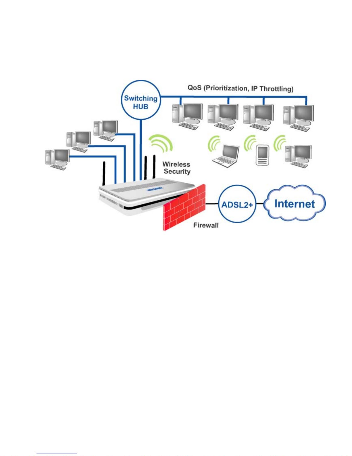
1.3 Applications of the BEC 7300N
Page 10

10
Chapter 2
Product Overview
Standards-Based Technology
The BEC 7300N Wireless Rout er utiliz es the 802.11n st andard. The IEEE 802.11n standard
is an extension of t he 802.11g standard. It incr eases t he dat a rate up to 300 Mb ps w ithin th e
2.4GHz band, utiliz ing OFDM technology . This means that in most env ironments, w ithin the
specified range of t hi s device, you will be abl e to t ransfer large files quickly or even w atch a
movie in MPEG format over your network without noticeable delays. This technology works
by transmitting high-speed digital data over a radio wave utilizing OFDM (Orthogonal
Frequency Division Multiplexing) technology. OFDM works by splitting the radio signal into
multiple smaller sub-si gnals that are then t ransmitted si multaneously at different fr equencies
to the receiver. OFDM reduces the amount of crosstalk (interference) in signal
transmissions.
Installation Considerations
The BEC 7 300N Wirel ess Router le ts you acc ess your ne twork, usin g a wirel ess connection,
from virtually anywhere within its operating range. Keep in mind, however, that the number,
thickness and l ocation o f walls, cei lings, or other objects that th e wirel ess signals must p ass.
Keep the number of walls and ceilings between the BEC 7300N and other network devices
to a minimum - each wall or ceiling can reduce your BEC 7300N wireless product’s range
from 3-90 feet (1-30 meters.)
Position your devices so that the number of walls or ceilings is minimized. Be aware of the
direct line between network devices. Position the devices so that the signal will travel
straight through a wall or ceiling (instead of at an angle) for better reception. Building
Materials can impe de the w ireless si gnal - a solid metal door or alu minium st uds may hav e a
negative effect on range.
Try to position wireless devices and computers with wireless adapters so that the signal
passes throug h dr y wall or open doorw ay s and not other materials. Keep your product away
(at least 3-6 feet or 1-2 meter s) from electrical devices or appliances that generate extreme
RF (radio frequency) noise.
Page 11
11
2.1 Important Notes
2.2 Package Contents
BEC 7300N ADSL2+ Router
CD-ROM containing the onli ne manual
RJ-1 1 ADSL/telepho ne Cable (1.8M)
Ethernet (CAT-5 LAN) Cable (1.8M Straight)
AC-DC power adapter (12V DC, 1A): for 7300N
Quick Start Guide (1 05*150 mm)
Antennas (3 pcs)
Place the BEC 7300N on a stable surface.
Only use the power adapter that comes with the package. Using
a different voltage rating power adaptor may damage the router.
Attention
Do not use the BEC 7300N in high humidity or high
temperatures.
Do not use the same p ower sour ce for the BEC 7300N as oth er
equipment.
Do not open or re pair the cas e yoursel f. If the BEC 7300N is too
hot, turn off the power immediately and have it repaired at a
qualified service center.
Avoid using this product and all accessories outdoors.
Warning
Page 12
12
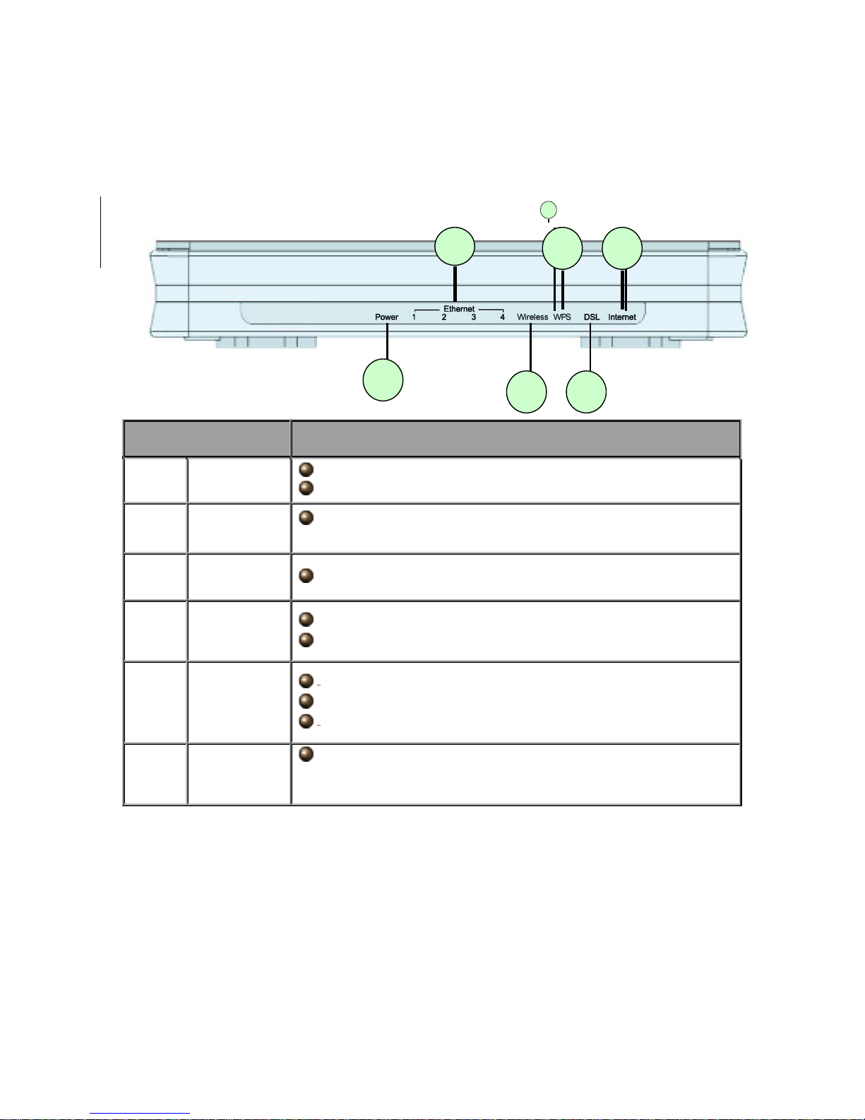
2.3 The Front LEDs
LED Meaning
1 Internet :
Lit red when WAN port fails to get IP address.
Lit green when WAN port gets IP address successfully.
2 DSL:
Lit when successfully connected to an ADSL DSLAM
(“linesync”).
3. WPS Blinking when WPS is in progress.
4 Wireless:
Lit green when the wireless connection is established.
Flashes when sending/receiving data.
5
Ethernet
Port 1-4:
Lit when connected to an Ethernet device.
Green for 100Mbps; Orange for 10Mbps.
Blinking when data is Transmitted / Received.
6 Power :
When the power is plugged in, it will lit Red and when the
system is ready, it will lit Green. Whilst the system is rebooting
or firmware upgrading, the LED light flashes.
1
1
1
3 5 6 4 2
Page 13
13
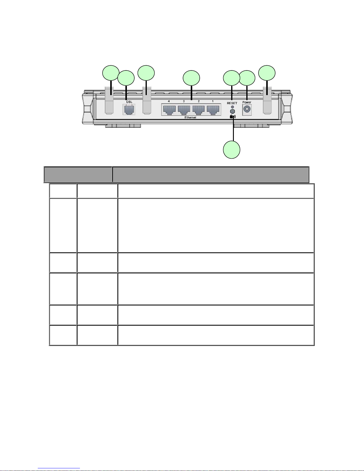
2.4 The Rear Ports
1 Power
Connect the supplied power adapter to this jack.
2 Reset
After the router is powered on, press this reset button using the
end of paper clip or other small pointed object to reset the router
and to restore it to factory default settings.
1. Recovery procedures for non-
working routers (e.g. after a
failed firmware upgrad e flash ).
2. Recovery procedures for a lost web interface password:
3 WPS
Push WPS button to trigger Wi-Fi Protected Setup function.
4
Ethernet
Connect a UTP Ethernet cable (Cat-5 or Cat-5e) to one of the
four LAN ports when connecting to a PC or an office/home
network of 10Mbps or 100Mbps.
Note: Only Ethernet port 1 can be used for EWAN.
5 DSL
Connect the supplie d RJ -
1 1 (“ teleph one” ) cabl e to this port when
connecting to the ADSL/telephone network.
6 Antenna
Connect the detachable antenna to this port.
Port Description
3
Page 14

14
Before powering on the router to enter the recovery process, please
configure the IP address of the PC as 192.168.1.100 and procee d with
the following step by step guide.
1. Power the router off.
2. Hold the "Reset Button”.
3. Power on the router. Then Router's IP will reset to Emergency IP
address (Say 192.168.1.1)
4. Download the firmware.
The detail instruction in Reset Button
1. Recovery procedur e s for n on-working routers ( e. g . a f t er a fai l ed firmware upgrade fl ash):
Hold the Reset Button on the back of the modem in. Keep thi s button held in and turn o n the
modem. Once the lights on the modem have stopped flashing, release the Reset Button.
The modem's emergency-reflash web interface will then be accessible via
http://192.168.1.1 where you can upload a firmware image to restore the modem to a
functional state. Please note that the modem will only respond via its web interface at this
address, and will not respond to ping requests from your PC or to telnet connections.
2.5 Cabling
One of the most common causes of problems is because of bad cabling or ADSL line(s).
Page 15

15
Make sure that all co n nect e d d evices are turned on. O n th e front of the product is a ba nk of
LEDs. V eri fy that t he LAN Link and ADSL l ine LEDs are li t. If th ey are not , ver ify that y ou are
using the proper cables.
Ensure that all other devices connected to the same telephone line as your router (e.g.
telephones, fax machines, analog modems) have a line filter connected between them and
the wall socket (unless you are using a Central Splitter or Central Filter installed by a
qualified and li censed electrician) , and t o ensure t hat all line fil ters ar e correctly inst alled an d
the right way around. Missing line filters or line filters installed being the wrong way around
can cause problems with your ADSL connection, which includes frequent disconnections.
Chapter 3
Installation
Page 16

16
You can configure the BEC 7300N rout er thr oug h the c onveni ent an d user -friendly inter fac e
of a web browser. Most popular operating systems such as Linux and Windows
98/NT/2000/XP/Me include a web browser as a standard application.
3.1 Before Configuration
PCs must have a properly installed Ethernet interface which connects to the router directly
or through an external repeater hub. In addition, PCs must have TCP/IP installed and
configured to ob tain an IP address through a DHCP server or a fixed IP address t hat must be
in the same subn et as the ro uter. The default IP ad dress o f the r outer is 192.168.1.1 and the
subnet mask is 255.255.255.0 (i.e. any attached PC must be in the same subnet, and have
an IP address in the range between 192.168.1.1 and 192.168.1.253). The easiest way is to
configure the PC is t o obtai n an IP address automati cally from the r outer using DHCP. If y ou
encounter any problems accessing the router’s web interface you are advised to uninstall
any kind of sof tware firew all on your PC s, as they can ca use problem s when tryi ng to access
the 192.168.1.1 IP address of the router.
Please follow the steps below for installation on y our P C’s network environment. First of all,
check your PC’s network components. The TCP/IP protocol stack and Ethernet network
adapter must be installed. If not, please refer to your Windows-related or other operating
system manuals.
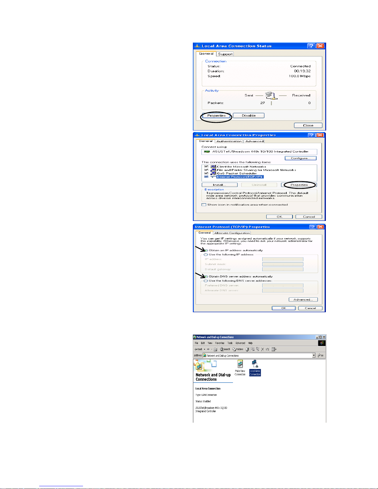
Configuring a PC in Windows XP
1. Go to Start / Control Panel (in Classic
View). In the Control Panel, double-click
on Network Connections
2. Double-click Local Area Connection.
Any TCP/IP cap able w orkst ation ca n be used to comm unicate w ith or
through the BEC 7300N. To configure other types of workstations,
please consult the manufacturer’s documentation.
Page 17
17
3. In the Local Area Connection Status
window, click Properties.
4. Select Internet Protocol (TCP/IP) and
click Properties.
5. Select the Obtain an IP address
automatically and the Obtain DNS
server address automatically radio
buttons.
6. Click OK to finish the configuration.
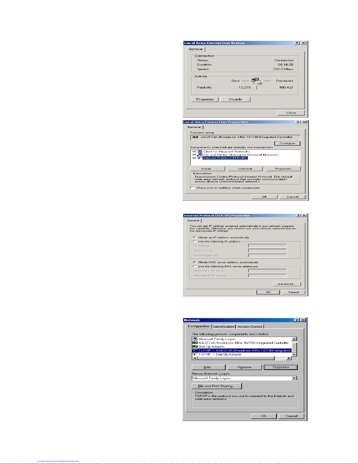
Configuring a PC in Windows 2000
1. Go to Start / Settings / Control Panel.
In the Control Panel, double-click on
Network and Dial-up Connections.
2. Double-click Local Area Connection.
Page 18
18
3. In the Local Area Connection Status
window click Properties.
4. Select Internet Protocol (TCP/IP) and
click Properties.
5. Select the Obtain an IP address
automatically and the Obtain DNS
server address automatically radio
buttons.
6. Click OK to finish the configuration.
Configuring PC in Windows 98/Me
1.Go to Start / Settings / Control P anel.
In the Control Panel, double-click on
Network and choose the
Configuration tab.
2.Select TCP/IP ->NE2000 Compatible,
or the name of your Network Interface
Card (NIC) in your PC.
Page 19
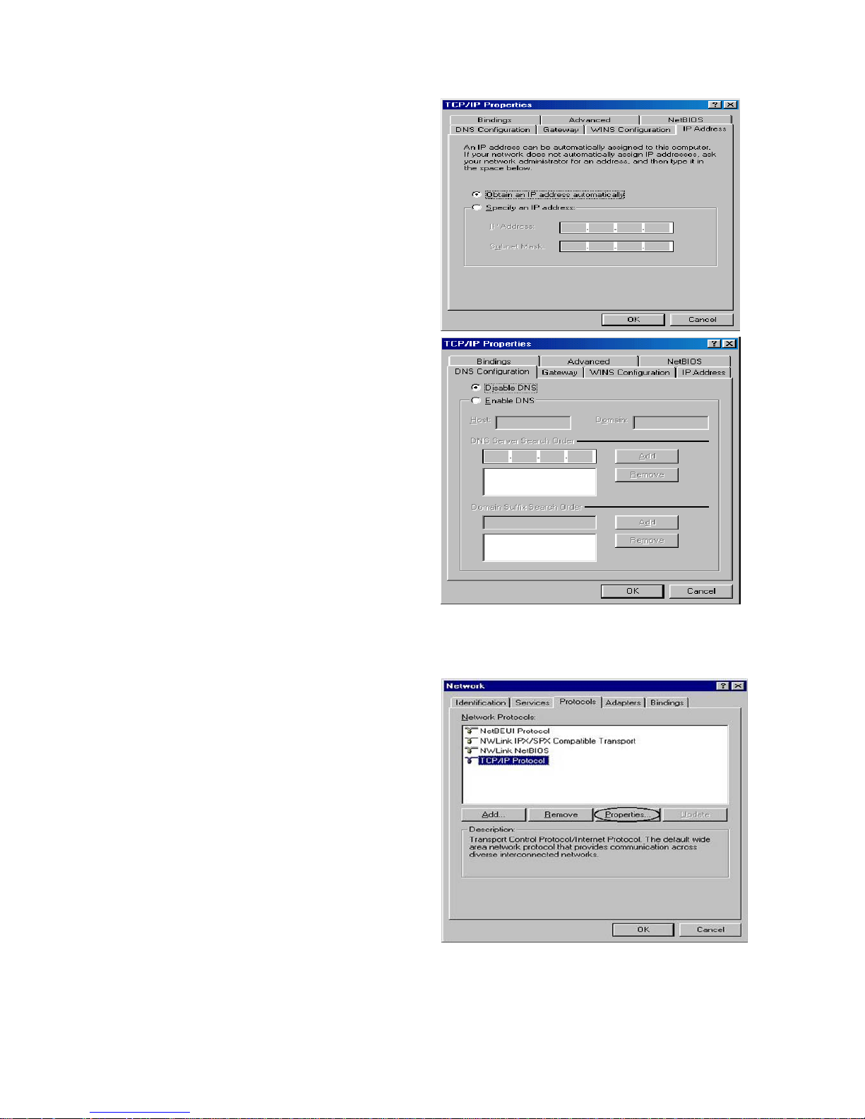
19
3.Select the Obtain an IP address
automatically radio button.
4.Then select the DNS Configuration tab.
5.Select the Disable DNS radio button
and click OK to finish the configuration.
Configuring PC in Windows NT4. 0
1.Go to Start / Settings / Control Panel. In
the Control Panel, double-click on
Network and choose the Protocols tab.
2.Select TCP/IP Protocol and click
Properties.
Page 20
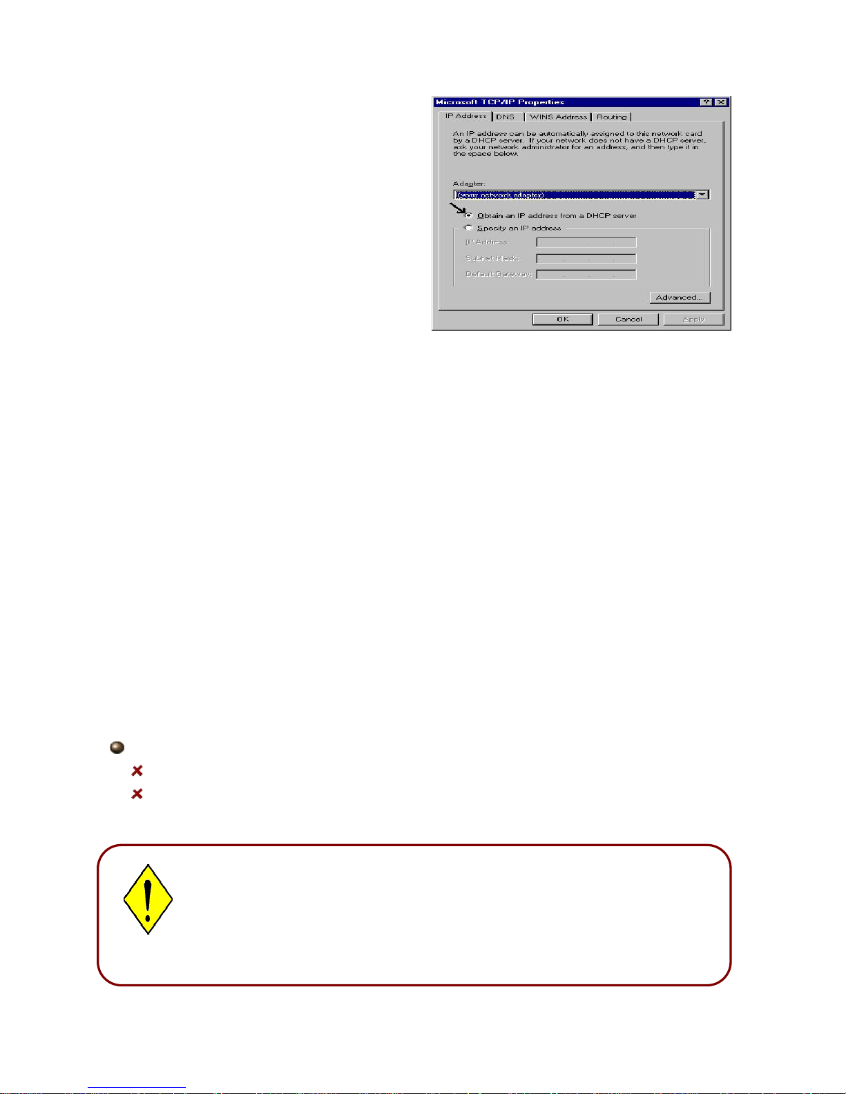
20
3.Select the Obtain an IP address from a
DHCP server radio button and click OK.
3.2 Factory Default Settings
Before configuring the BEC 7300N router, you need to know the following default settings.
Web Interface: (Username and Password)
Username: admin
Password: admin
The default username and password are “admin” and “admin” respectively.
Attention
If you ever forget the username/password to login to the router, you
may press the RESET button up to 6 seconds then release it to restore
the factory default settings.
Caution: After pressing the RESET button for more than 6 seconds then release it, to
be sure you power cycle the device again.
Attention
Page 21

21
LAN Device IP Settings:
IP Address: 192.168.1.1
Subnet Mask: 255.255.255.0
ISP setting in WAN site:
PPPoE
DHCP Server:
DHCP server is enabled.
Start IP Address: 192.168.1.100
IP pool counts: 100
3.3 LAN and WAN Port Addresses
The parameters of LAN and WAN ports are preset at the factory. The default values are
shown below.
LAN Port WAN Port
IP address 192.168.1.1 The PPPoE function is
enabled to automatically get
the WAN port configuration
from the ISP, b ut y ou h av e to
set the username and
password first.
Subnet Mask 255.255.255.0
DHCP server function Enabled in ports 1, 2, 3 and 4
IP addresses for
distribution to PCs
100 IP addresses continuing
from 192.168.1.100 thr oug h
192.168.1.199
Page 22

22
3.4 Information from your IS P
Before configuring this device, you have to check with your ISP (Internet Service Provider)
what kind of services are provided, such as PPPoE, PPPoA, MPoA or Pure Bridge.
Gather the information as illustrated in the following table and keep it for reference.
PPPoE VPI/VCI, VC-based/LLC-based multiplexi
ng, Username, Password,
Service Name, and Domain Name System (DNS) IP address (it can be
automatically assigned by your ISP when you connect or be set
manually).
PPPoA VPI/VCI, VC-based/LLC-
based multiplexing , U ser nam e, Password, and
Domain Name System (D
NS) IP address (it can be automatically
assigned by your ISP when you connect or be set manually).
RFC1483 Bridged VPI/VCI, VC-based/LLC-based multiplexing to use Bridged Mode.
RFC1483 Routed VPI/VCI, VC-based/LLC-based multiplexing, IP address, Subnet mask,
Gateway address, and Domain Name System (DNS) IP address (it is
fixed IP address).
3.5 Configuring with your BEC 7300N
Easy Sign On:
After setting up the router with appropriate cables plugged, proceed to load the internet
browser to surf Internet, the EZSO WEB GUI will be popped up and request you to input
some basic information you get from ISP. After this, you can surf Internet right away.
1. To configure this device, you must have IE 5. 0 / Net scape 4.5 or
above installed
2. You may configure the router for Internet access in two ways:
(A) Easy Sign-On (EZSO) (B) Web Configuration
Page 23
23
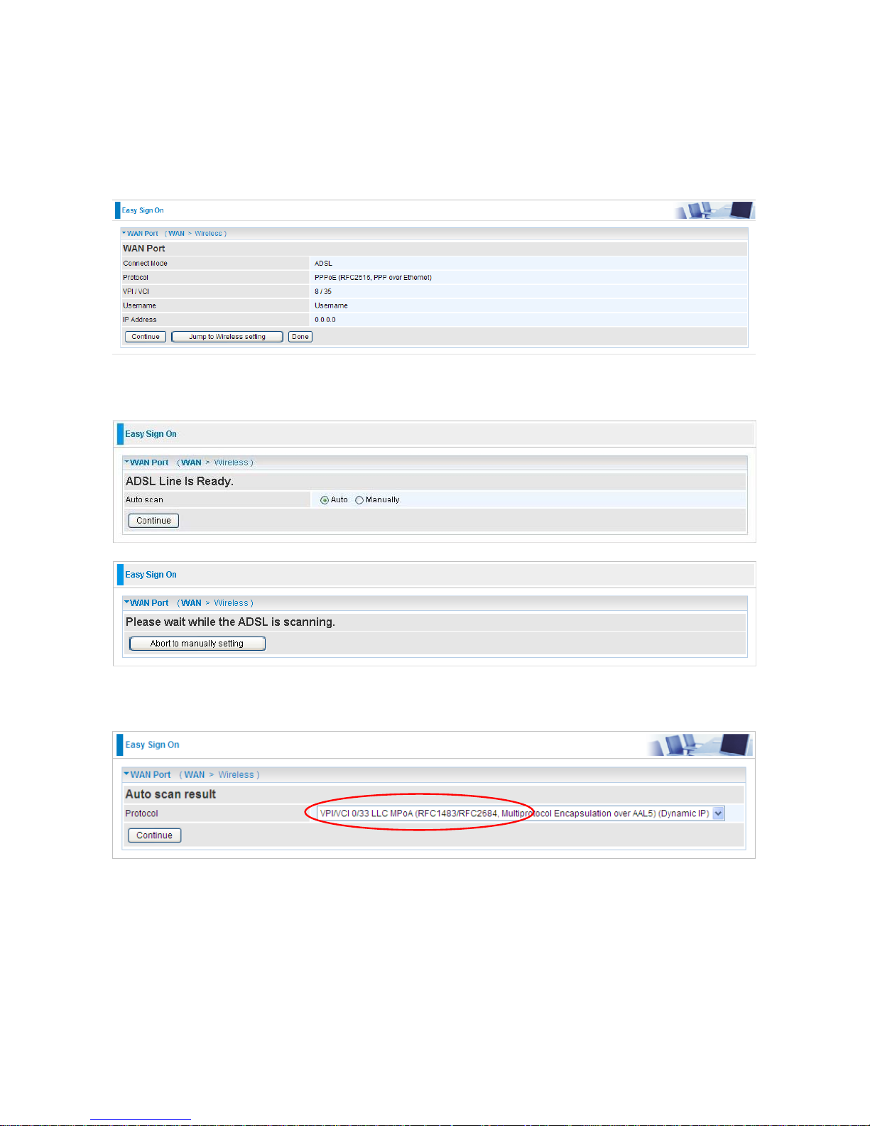
Follow the Easy Sign-On configuration wizard and it will guide you to complete the basic
network configuration.
1. Click continue.
2. Choose “Auto” or “Manually” to scan ADSL information.
3. Show Auto scan result - Protocol information.
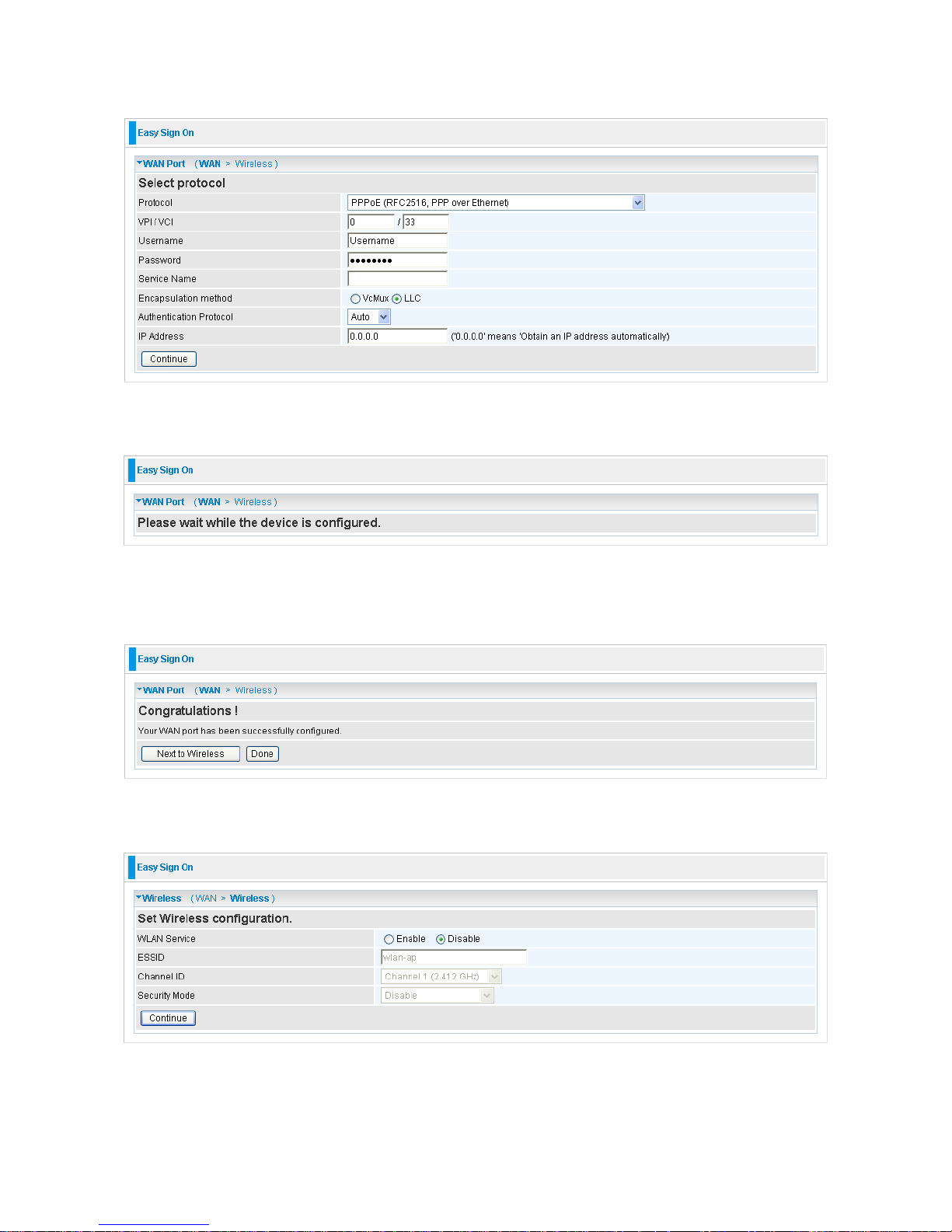
4. Please enter “Username” and “Password” as supplied by your ISP (Internet Service
Provider) and click continue.
Page 24
24
5. Wait for the device to be configured.
6. You’ve have completed the W A N p or t se t up and now click “ Nex t to Wir eless” to proceed
to the wireless configuration.
7. Please configure the Wireless LAN setting and click Continue.
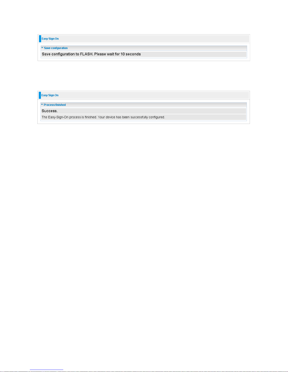
8. Save Configuration.
Page 25
25
9. Congratulations!! You’ve completed the setup procedure and you are now ready to surf
the Internet, enjoy.
Page 26
26
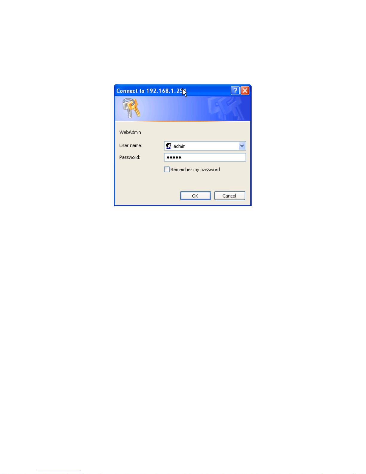
Web Configuration:
Open your web brow ser , enter the IP address o f your router , w hich by default is 192.168.1.1,
and click “Go”, a user name and password window prompt appears. The default username
and password are “admin” and “admin”.
Congratulations! You have successfully logged on to your BEC 7300N Router!
Page 27
27
Chapter 4
Basic Configuration
Once you have logged on to your BEC 7300N Router via your web browser, you can begin
to set it up according to your requirements. On the configuration homepage, the left
navigation pane links you directly to the setup pages, which include:
Advance (Switch to Advance Configuration mode)
Status
Quick Start
WAN
WLAN
Page 28
28
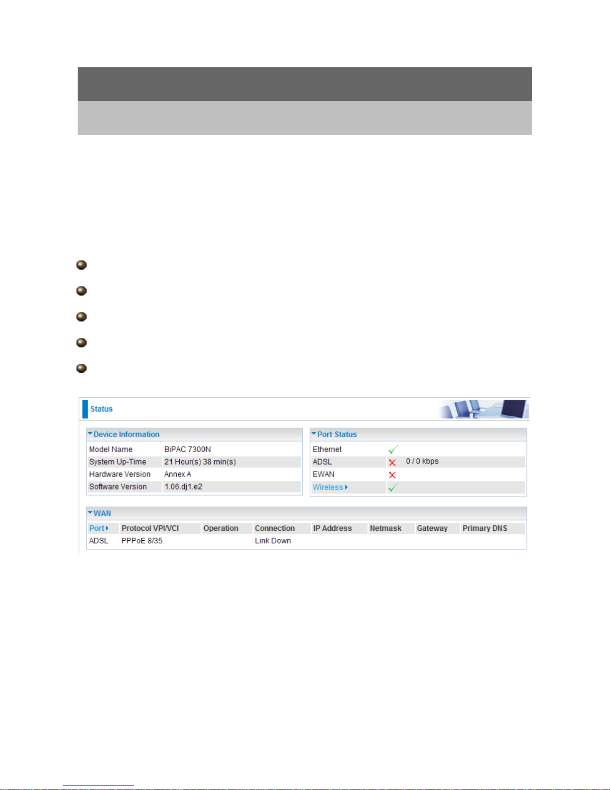
4.1 Status
Device Information
Model Name: Provide a name for the router for identification purposes.
System Up-Time: Records system up-time.
Hardware Version: Device version
Software Version: Firmware version
Port Status
Port Status:User can l ook up to see if they ar e connected to Eth ernet, ADSL or Wireless.
WAN
Port: Name of the WAN connection.
Protocol VPI/VCI: Virtual Path Identifier and Virtual Channel Identifier
Operation: Current available operation.
Connection: The current connection status.
IP Addr ess: WAN port IP address.
Primary DNS: The IP address of the primary DNS server.
Net mask: WAN port IP subnet mask.
Gateway: The IP address of the default gateway.
Page 29
29
4.2 Quick Start
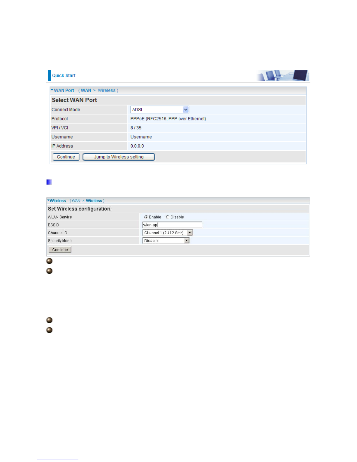
Set Wireless configuration
WLAN Service: Default setting is set to Enable.
ESSID: The ESSID is the unique name of a wireless access point (AP) to be
distinguished from another. For security purpose, change to a unique ID name to the AP
which is already built-in to the router’s wireless interface. It is case sensitive and must not
excess 32 character s. Make sure y our wireless cl ients hav e exactly the ES SID as the dev ice,
in order to get connected to your network.
Channel ID: Select the ID channel that you would like to use.
Security Mode: You can disable or enable with WPA or WEP for protecting wireless
network. The default mode of wireless security is Disable.
Page 30
30
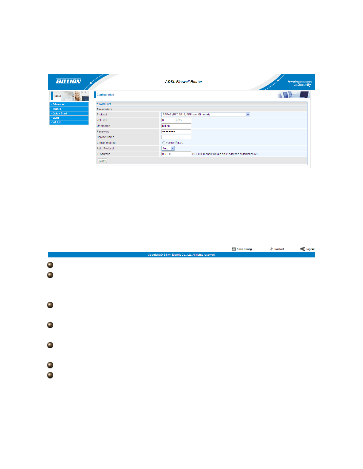
4.3 WAN
VPI/VCI: Enter the VPI and VCI information provided by your ISP.
Username: Enter the username provided by your ISP. You can input up to 128
alphanumeric characters (case sensitive). This is in the format of “username@ispname”
instead of simply “username”.
Password: Enter the password provided by your ISP. You can input up to 128
alphanumeric characters (case sensitive)
Service Name: This item is for ident ifica ti on purpos es. If it i s req uired, your ISP prov i des
you the information. Maximum input is 15 alphanumeric characters.
Encap. method: Select the encapsulation format, the default is LLC. Select the one
provided by your ISP
Auth. Protocol: Default is Auto. Your ISP advises on using Chap or Pap.
IP Addr ess: Your WAN IP address. Leave this at 0.0.0.0 to automatically obtain an IP
address from your ISP.
Page 31

31
4.4 WLAN
WLAN Service: Default setting is set to Enable.
ESSID: The ESSID is the unique name of a wireless access point (AP) to be
distinguished from another. For security propose, change to a unique ID name to the AP
which is already built-in to the router’s wireless interface. It is case sensitive and must not
excess 32 character s. Make sure y our wireless cl ients hav e exactly the ES SID as the dev ice,
in order to get connected to your network.
Note: ESSID is case sensitive and must not excess 32 characters.
Hide ESSID: It is function in which transmits its ESSID to the air so that when wireless
client searches for a ne twor k, router ca n then be di scover ed and r ecog nized. D efault se tting
is Disable.
Enable: Select Enable if you do not want broadcast your ESSID. When select
Enable, no one will be able to locate the Access Point (AP) of your router.
Disable: When Disable is selected, you can allow anybody with a wireless client to
be able to locate the Access Point (AP) of your router.
Regulation Domain: There are seven Regulation Domains for you to choose from,
including North America (N.America), Europe, France, etc. The Channel ID will be
different based on thi s se tti ng .
Channel ID: Select the ID channel that you would like to use.
Page 32

32
Security Mode: You can disable or enable with WPA or WEP for protecting wireless
network. The default mode of wireless security is Disable.
Security Parameters
WPA Pre-Shared Key
WPA Shared Key: The key for network authentication. The input format is in character
style and the key size should be in the range between 8 and 63 characters.
Group Key Renewal: The period of renewal time for ch ang i ng t he s ecu r i ty key between
wireless client and Access Point (AP). This process is done automatically.
WPA2 Pre-Shared Key
WPA 2 Shar ed K ey: The key for network authentication. The input format is in character
style and key size should be in the range between 8 and 63 characters.
Group Key Renewal: The period of renewal time for ch ang i ng t he s ecu r i ty key between
wireless client and Access Point (AP). This process is done automatically.
Page 33

33
WEP
WEP Authentication: To prevent unauthorized wireless stations from accessing data
transmitted over the network, the r outer offers secure dat a encryption , known as WEP. If you
require high secur ity for transmissio ns, there are thr ee options t o select from: Open Sy stem ,
Share key or Both.
Default Used WEP Key: Select the encryption key ID; please refer to Key (1~4) below.
Passphrase: This is used to generate WEP keys automatically based upon the input
string and a pre-defined algorithm in WEP64 or WEP128. You can input the same string in
both the AP and Client card settings to generate the same WEP keys. Please note that you
do not have to enter Key (1-4) as below when the Passphrase is enabled.
Ke y (1 -4): Enter the key to encrypt wireless data. To allow encrypted data transmission,
the WEP Encryption Key values on all wireless stations must be the same as the router.
There are four keys for your selection. The input format is in HEX or ASCII style, 5 and 13
ASCII codes are required for WEP64 and WEP128 respectively no any separator is
included.
Page 34

34
Chapter 5
Advance Configuration
Once you have logg ed on to your BEC 7300N Router via your web browse r , you can begin to
set it up accordi ng t o your req uirem ent s. On the c on figurat ion ho mepag e, the l e ft nav ig ation
pane links you directly to the setup pages, which include:
Basic (Switch to Basic Configuration Mode)
Status (ADSL S t atus, ARP Table, DHCP Table, System Log, Firewal l Log, UPnP Portmap)
Quick Start
Configuration (LAN, WAN, System, Firewall, QoS, Virtual Server, Time Schedule and
Advanced)
The following sections provide an overview of the settings available for configuring your
router.
Page 35

35
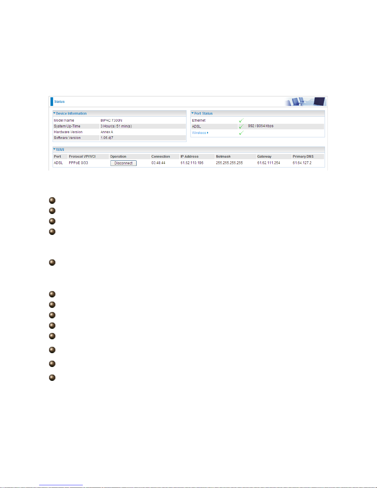
5.1 Status
Device Information
Host Name: Provide a name for the router for identification purposes. Host Name lets
you change the router name.
Page 36

36
System Up-Time: Records system up-time.
Current time: Set the current time. See the Time Zone section for more information.
Hardware Version: Device version.
Software Version: Firmware version.
MAC Address: The LAN MAC address.
WAN
Port: Name of the WAN connection.
Protocol VPI/VCI: Virtual Path Identifier and Virtual Channel Identifier
Operation: Current available operation.
Connection: The current connection status.
IP Addr ess: WAN port IP address.
Port Status:User can l ook up to see if they ar e connected to Eth ernet, ADSL or Wireless.
Net mask: WAN port IP subnet m ask.
Gateway: The IP address of the default gateway.
Primary DNS: The IP address of the primary DNS server.
Port Status
Page 37

37
5.1.1 ADSL St atus
DSP Firmware Version: DSP code version
DMT Status: Current DMT Status
Operational Mode: To show the state when user select “AUTO” on connect mode.
Upstream: Upstream rate.
Downstream: Downstream rate.
SNR Margin (Upstream): This is noise margin in upstream.
SNR Margin (Downstream): This is noise margin in downstream.
Line Attenuation (Upstream): This is attenuation of signal in upstream.
Line Attenuation (Downstream): This is attenuation of signal in downstream.
ADSL Mode: There are four modes “Open Annex Type and Follow DSLAM’s
Setting”, ”Annex A”, ”Annex L”, ”Annex M” and “Annex J” that user can select for this
connection.
Modulator: There are seven modes “AUTO”,”ADSL
Multimode”,”ADSL2”, ”ADSL2+”,”G.Lite”, “T1.413” and “G.DMT” that user can select for
this connection.
Page 38

38
5.1.2 ARP Table
This section displays the router’s ARP (Address Resolution Protocol) Table, which shows
the mapping of Internet (IP) addresses to Ethernet (MAC) addresses. This is useful as a
quick way of determini ng t he MA C addr ess o f the network interface o f your PC s to use with
the router’s Firewall – MAC Address Filt er function. See the Firewall section o f this manual
for more information on this feature.
IP Addr ess: It is IP Address of internal host that join this network.
MAC Address: The MAC address of internal host.
5.1.3 DHCP Table
IP Address: The current corresponding DHCP-assigned dynamic IP address of the
device.
MAC Address: The MAC Address of internal dhcp client host.
Client Host Name: The Host Name of internal dhcp client.
Register Information: Register time informatio n
Page 39

39
5.1.4 System Log
Display system log s accumulate d up to the pr esent time. You can trace hi storical in formation
with this function.
5.1.5 Firewall Log
Firewall Log displays log information of any unexpected action with your firewall settings.
This page displays the router’s Firewall Log entries. The log shows log entries when you
have enabled Intrusion Detection or Block WAN PING in the Configuration – Firewall
section of the interface. Please see the Firewall section of this manual for more details on
how to enable Firewall logging.
Page 40

40
5.1.6 UPnP Portmap
The section lists all port-mappi ng establ ished usi ng UPnP (Univ ersal Plug and Play). Please
see the Advanced section of this manual for more details on UPnP and the router’s UPnP
configuration options.
Page 41

41
5.2 Quick Start
ADSL
Connect mode: ADSL
Protocol: The current ATM protocol in the device
VPI / VCI: The current value of VPI / VCI in the device
IP address: To show current value of IP address in the device.
EWAN
Click on Continue to choose the Protocol to c onnect with E WAN or cl ick Jump to Wireless
Setting to use Protocol: Obtain an IP Address Automatically to connect and setup wireless
settings at the same time.
Page 42

42
Obtain an IP Ad dress A utomatically
When connecting to the ISP, BEC 7300N also functions as a DHCP client. BEC 7300N can
automatically obtain an IP address, subnet mask, gateway address, and DNS server
addresses if the ISP assigns this information via DHCP.
Protocol: The current ATM protocol in the device
Click on the Continue button and wait for your connection to be connected.
If connection is successful the following image will be shown.
Page 43

43
Fixed IP Address
Select this option to set static IP information. You will need to enter in the Connection type,
IP address, Netmask, and gateway address, provided to you by your ISP. Each IP address
entered in the fiel ds must be in the appropriate IP form, whi ch is four IP octets sep arated by
a dot (x.x.x.x). The Router will not accept the IP address if it is not in this format.
Protocol: The current ATM protocol in the device
IP Addr ess: Your WAN IP address. Leave this at 0.0.0.0 to automatically obtain an IP
address from your ISP.
Netmask: The default i s 0.0.0.0. User ca n change i t to other such as 255.2 55.255.0. T ype
the subnet mask assigned to you by your ISP (if given).
Gateway: You must specify a gateway IP address (supplied by your ISP)
Click on the Continue button and wait for your connection to be connected.
If connection is successful the following image will be shown.
Page 44

44
PPPoE
PPPoE (PPP over Ethernet) provides access control in a manner similar to dial-up services
using PPP.
Protocol: The current ATM protocol in the device
Username: Enter the username provided by your ISP. You can input up to 128
alphanumeric characters (case sensitive). This is in the format of “username@ispname”
instead of simply “username”.
Password: Enter the password provided by your ISP. You can input up to 128
alphanumeric characters (case sensitive).
Service Name: Enter a name for this connection.
IP Addr ess: Your WAN IP address. Leave this at 0.0.0.0 to automatically obtain an IP
address from your ISP.
Auth. Protocol: Default is Auto. Your ISP advises on using Chap or Pap.
Click on the Continue button and wait for your connection to be connected.
If connection is successful the following image will be shown.
Page 45

45
Set Wireless configuration
WLAN Service: Default setting is set to Enable.
ESSID: The ESSID is the unique name of a wireless access point (AP) to be
distinguished from another. For security propose, change to a unique ID name to the AP
which is already built-in to the router’s wireless interface. It is case sensitive and must not
excess 32 character s. Make sure y our wireless cl ients hav e exactly the ES SID as the dev ice,
in order to get connected to your network.
Channel ID: Select the ID channel that you would like to use.
Security Mode: You can disable or enable with WPA or WEP for protecting wireless
network. The default mode of wireless security is Disable.
Page 46

46
5.3 Configuration
Click this item to access the follow ing sub-items tha t configur e the A DSL router: LAN, WAN,
System, Firewall, QoS, Virtual Server, Time Schedule and Advanced.
These functions are described in the following sections.
5.3.1 LAN (Local Area Network)
A Local Area Network (LAN) is a shared communication system to which many computers
are attached and is limited to the immediate area, usually the same building or floor of a
building.
There are six items within the LAN section: Ethernet, IP Alias, Wireless, Wireless
Security, WPS and DHCP Server.
5.3.1.1 Ethernet
The router support s more tha n o ne Ether net I P addr ess es in t he LA N, and w i th disti nct LAN
subnets through which you can access the Internet at the same time. Users usually only
have one subnet in their LAN. The default IP address for the router is 192.168.1.1.
IP Addr ess: The default IP on this router.
Netmask: The default subn et mask on t his router.
Page 47

47
RIP: RIP v1, RIP v2, RIP v1+v2 and RIP v2 Multicast.
5.3.1 .2 IP Alias
This function allows the creation of multiple virtual IP interfaces on this router. It helps to
connect two or more lo cal networks to the IS P or remote no de. In this case, a n internal router
is not required.
IP Addr ess: Specify an IP address on this virtual interface.
Netmask: Specify a subnet mask on this virtual interface.
5.3.1.3 Wireless
Parameters
WLAN Service: Default setting is set to Enable.
Mode: The defau lt sett ing is 802.11g+n (Mixed mode). If you do not know or have both
Page 48

48
11g and 11n devices in your network, then keep the default in mixed mode. From the
drop-down manual, you can select 802.11g if you have only 11g card. If you have only 11b
card, then select 802.11b. If you have only 11n card, then select 802.11n.
ESSID: The ESSID is the unique name of a wireless access point (AP) to be
distinguished from another. For security propose, change to a unique ID name to the AP
which is already built-in to the router’s wireless interface. It is case sensitive and must not
excess 32 character s. Make sure y our wireless cl ients hav e exactly the ES SID as the dev ice,
in order to get connected to your network.
Note: ESSID is case sensitive and must not excess 32 characters.
Hide ESSID: It is function in which transmits its ESSID to the air so that when wireless
client searches for a ne twor k, router ca n then be di scover ed and r ecog nized. D efault se tting
is Disable.
Enable: Select Enable if you do not want broadcast your ESSID. When select
Enable, no one will be able to locate the Access Point (AP) of your router.
Disable: When Disable is selected, you can allow anybody with a wireless client to
be able to locate the Access Point (AP) of your router.
Regulation Domain: There are seven Regulation Domains for you to choose from,
including North America (N.America), Europe, France, etc. The Channel ID will be
different based on thi s se tti ng .
Channel ID: Select the ID channel that you would like to use.
Channel Wdith: Select either 20 MHz or 20/40 MHz for the channel bandwidth. The
higher the bandwidth the better the performance will be.
Tx Power Level: It is function that enhances the wireless transmitting signal strength.
User may adjust this power level from minimum 0 up to maximum 100.
Note: The Power Lev el maybe di f ferent in eac h access netw ork user premises environment
and choose the most suitable level for your network.
AP MAC Address: It is a unique hardware address of the Access Point.
AP Firmware Version: The Access Point firmware version.
WPS service: Enable / disable
WPS State: Current WPS state in AP. It is be used for WCN (Windows Connect Now).
Configured: This AP i s be con figured v ia WPS. It is not all ow to con figur e via WCN.
Unconfigured: This AP is un-configured via WPS. It can be configure via WCN.
Wireless Distribution System (WDS)
Page 49

49
It is a wireless access point mode that enables wireless link and communication with other
access point. It is easy to be installed, simply define the peer’s MAC address of the
connected AP. WDS takes advantages of cost saving and flexibility which no extra wireless
client device is required to bridge between two access points and extending an existing
wired or wireless infrastructure network to create a larger network.
WDS Service: The de faul t setting is Disable. Check Enable radio butto n to activate this
function.
1. Peer WDS MAC Address: It is the associated AP’s MAC Address. It is important that
your peer’s AP must include your MAC address in order to acknowledge and
communicate with each other.
2. Peer WDS MAC Address: It is the second associ ated AP’s MAC Address.
3. Peer WDS MAC Address: It is the third associated AP’s MAC Address.
4. Peer WDS MAC Address: It is the fourth associated AP’s MAC Address.
Note: For MAC Address, Semicolon ( : ) or Dash (-) must be included.
5.3.1.4 Wireless Security
You can disable or enable with WPA or WEP for protecting wireless network. The default
mode of wireless security is Disable.
Page 50

50
WPA Pre-Shared Key
WPA Algorithms: TKIP (Temporal Key Integrity Protocol) / AES (Advanced Encryption
Standard) utilizes a stronger encryption method and incorporates Message Integrity Code
(MIC) to provide protection against hackers.
WPA Shared Key: The key for network authentication. The input format is in character
style and key size should be in the range between 8 and 63 characters.
Group Key Renewal: The period of renewal time for changing the security key
automatically between wireless client and Access Point (AP).
WPA2 Pre-Shared Key
WPA2 Algorithms : TKIP (Temporal Key Integrity Protocol) / AES (Advanced Encryption
Standard) utilizes a stronger encryption method and incorporates Message Integrity Code
(MIC) to provide protection against hackers.
WPA2 Shared Key: The key for network authentication. The input format is in character
style and key size should be in the range between 8 and 63 characters.
Group Key Renewal: The period of renewal time for changing the security key
Page 51

51
automatically between wireless client and Access Point (AP).
WEP
WEP Authentication: To prevent unauthorized wireless stations from accessing data
transmitted over the network, the r outer offers secure dat a encryption , known as WEP. If you
require high secur ity for transmissio ns, there are thr ee options t o select from: Open System,
Share key or Both.
Default Used WEP Key: Select the encryption key ID; please refer to Key (1~4) below.
Passphrase: This is used to generate WEP keys automatically based upon the input
string and a pre-defined algorithm in WEP64 or WEP128. You can input the same string in
both the AP and Client card settings to generate the same WEP keys. Please note that you
do not have to enter Key (1-4) as below when the Passphrase is enabled.
Ke y (1 -4): Enter the key to encrypt wireless data. To allow encrypted data transmission,
the WEP Encryption Key values on all wireless stations must be the same as the router.
There are four keys for your selection. The input format is in HEX or ASCII style, 5 and 13
ASCII codes are required for WEP64 and WEP128 respectively no any separator is
included.
5.3.1.5 WPS
WPS feature is follow Wi-Fi Alliance WPS standard and it ease set up of security-enabled
Wi-Fi netw orks i n the h ome a nd small o f fice env ir onment. R educe s by hal f the use r st ep s t o
configure a network and supports two methods that are familiar to most consumers to
configure a network and enable security.
Page 52

52
Set up of security-enabled Wi-Fi network
Step 1: Note down the AP’s PIN from Web (Ex: 78749887).
Step 2: Open wireless client’s WPS utility (Ex: Atheros Jumpstart WPS utility), select
“Configure a wireless network” and apply “next” button.
Step 3: Enter AP’s PIN into the utility and click on the “next” button.
Page 53

53
Step 4: These are two ways to trigger AP as Enrolee role, you can choose one to do it.
Push AP’s WPS button 1 second and release it. Or
In the AP’s WPS configuration page, change Role to “Enrollee” and apply
“Start” button.
Step 5: Jumps tar t WPS utility search WPS AP.
Step 6: SSID and security will be generated automatically (You can change it) and apply
“next” button.
Page 54

54
Step 7: WPS set up complete. And you have set up security-enabled Wi-Fi networks.
Page 55

55
Set up of security-enabled Wi-Fi network using WCN in Vista
Step 1: Note down the AP’s PIN from Web (Ex: 78749887).
Step 2: Set WPS State to “Unconfigured” at Wireless page and click “Apply”.
Step 3: In Vista`s Control Panel, select Network and Internet and choose View network
computers and devices. Double click the “ADSL Firewall Router” icon and enter the AP`s
PIN code then click “Next”.
Page 56

56
Step 4: Enter the AP SSID and apply “Next” button.
Page 57

57
Step 5: Enter the Passphrase and apply “Next” button.
Step 6: WCN set up complete. And you have set up security-enabled Wi-Fi networks.
Page 58

58
Adding a new WPS device (wireless client) to a network - Use PBC Method
Step 1: Push AP’s WPS button more than one second and you will see AP’s WLAN led will
flashing per second.
Step 2: Open wireless client’s WPS utility, select “Join a wireless network” and apply “next”
button.
Note: After you push AP’s WPS button, below steps should be completed between 2
minutes.
Step 3: Select “Push the button on my access point” and apply “next” button.
Page 59

59
Step 4: New WPS device have join into the wireless network.
Adding a new WPS device (wireless client) to a network - Use PIN Method
Step 1: Open wireless client’s WPS utility, select “Join a wireless network” and apply “next”
button.
Page 60

60
Step 2: Note down the wireless client’s PIN (Ex: 41538142) and apply “Start” button for
active wireless client WPS PI N met hod.
Step 3: Enter wireless client’s PIN into “Enrollee’s PIN” of Web and apply “Start” button.
Page 61

61
Step 4: New WPS device have join into the wireless network.
Adding a new WPS device (wireless client) to a network - Use PIN Method
Step 1: Open wireless client’s WPS utility, select “Join a wireless network” and apply “next”
button.
5.3.1.6 DHCP Server
You can disable or enable the DHCP (Dynamic Host Configuration Protocol) server or
enable the router’s DHCP relay functions. The DHCP protocol allows your router to
dynamically assign IP addresses to PCs on your network if they are configured to obtain IP
addresses automatically.
DHCP Server Mode: Disable
To disable the router’s DHCP Server, check Disabled and then click Apply. When the
DHCP Server is disabled, you will need to manually assign a fix ed IP address to e ach PC on
your network, and set the default gateway for each PC to the IP address of the router (the
default is 192.168.1.1).
Page 62

62
DHCP Server Mode: DHCP Server
To configure the router’s DHCP Server, check DHCP Server. You can then configure
parameters of the DHCP Server including the IP pool (starting IP address and ending IP
address to be allocated to PCs on your network), lease time for each assigned IP address
(the period of time the IP address assigned will be valid), DNS IP address and the gateway
IP address. These details are sent to the DHCP client (i.e. your PC) when it requests an IP
address from the DHCP server. Click Apply to enable this function. If you check “Use
Router as a DNS Server”, the AD SL Router p erforms the d omain name look up, finds t he IP
address from the ou tsi de netw ork auto maticall y and for wards i t back to t he req uesting PC in
the LAN (your Local Area Network).
DHCP Server Mode: DHCP Relay
If you check DHCP Relay and then you must enter t he IP address of the DHCP server whi ch
assigns an IP address back to the DHCP client in the LAN. Use this function only if advised
to do so by your network administrator or ISP. Click Apply to enable this function.
Page 63

63
5.3.2 WAN (Wide Area Network)
A WAN (Wide Area Network) is an outside connection to another network or the Internet.
There are two items within the WAN section: WAN Profile and ADSL Mode.
Page 64

64
5.3.2.1 WAN Profile
Main Port--ADSL
PPPoE Connection (ADSL)
PPPoE (PPP over Ethernet) provides access control in a manner similar to dial-up services
using PPP.
Description: A user-definable name for this connecti on.
VPI/VCI: Enter the VPI and VCI information provided by your ISP.
Encap. method: Select the encapsulation format, the default is LLC. Select the one
provided by your ISP
Username: Enter the username provided by your ISP. You can input up to 128
alphanumeric characters (case sensitive). This is in the format of “username@ispname”
instead of simply “username”.
Password: Enter the password provided by your ISP. You can input up to 128
alphanumeric characters (case sensitive)
Service Name: This item is for ident ifica ti on purpos es. If it i s req uired, your ISP prov i des
you the information. Maximum input is 15 alphanumeric characters.
NAT: The N AT (Network Address Translation) feature allow s multi ple users to acc ess the
Internet through a single ISP account, sharing a single IP address. If users on your LAN
have public IP addresses and can access the Internet directly, the NAT function can be
disabled.
IP Address: Your WAN IP address. Leave this at 0.0.0.0 to automatically obtain an IP
Page 65

65
address from your ISP.
Auth. Protocol: Default is Auto. Your ISP advises on using Chap or Pap.
Obtain DNS Autom atically: Select this check box to use DNS.
Primary DNS/ Secondary DNS: Enter the IP addresses of the DNS servers. The DNS
servers are passed to the DHCP clients along with the IP address and the Netmask.
Connection:
Always on: If you want the router to establish a PPPoE session when starting up
and to automatically re-establish the PPPoE session when disconnected by the ISP.
Connect to Demand (un-select Always On): If you want to establish a PPPoE
session only when there is a packet requesting access to the Internet (i.e. when a
program on your computer att empts to acc ess th e Inter net). In t his m ode, you must s et
Idle Timeout value at same time.
Idle Timeout: Auto-disconnect the broadband firewall gateway when there is no activity
on the line for a predetermi ne d per iod of time. The minimum value is 10 minutes.
MTU: Maximum Trans mission Unit. The size of the largest datagram (excluding
media-specific headers) an IP attempts to send through the interface.
PPPoA Connection (ADSL)
PPPoA stands for Point to Point Protocol over ATM Adaptation Layer 5 (AAL5). It provides
access control and billing functionality in a manner similar to dial-up services using PPP.
Description: User-defi nabl e na me for the connect ion.
VPI/VCI: Enter the VPI and VCI information provided by your ISP.
Encapsulation method: Select the encapsulation format, the default is LLC. Select the
Page 66

66
one provided by your ISP
Username: Enter the username provided by your ISP. You can input up to 128
alphanumeric characters (case sensitive). This is in the format of “username@ispname”
instead of simply “username”.
Password: Enter the password provided by your ISP. You can input up to 128
alphanumeric characters (case sensitive).
NAT: The N AT (Network Address Translation) feature allow s multi ple users to acc ess the
Internet through a sing le IP accou nt, s hari ng a sing le IP a ddress. If users on y our L AN h av e
public IP addresses and can access the Internet directly, the NAT function can be disabled.
IP Address: Your WAN IP address. Leave this at 0.0.0.0 to automatically obtain an IP
address from your ISP.
Authentication Protocol: Default is Auto. Your ISP should advises you on whether to
use Chap or Pap.
Obtain DNS Automatically : Select this check box to use DNS.
Primary DNS/ Secondary DNS: Enter the IP addresses of the DNS servers. The DNS
servers are passed to the DHCP clients along with the IP address and the Netmask.
Connection:
Always on: The router will establish a PPPoA session when starting up and to
automatically re-establish the PPPoA session when disconnected by the ISP.
Connect to Demand (un-select Always On): If you want to establish a PPPoA
session only when there is a packet requesting access to the Internet (i.e. when a
program on your com p uter attempts to acce s s the Internet). In this mod e, y ou must set
Idle Timeout value at same time.
Idle Timeout: Auto-disconnect the broadband firewall gateway when there is no activity
on the line for a predetermined period of time. The minimum value is 10 minutes.
MTU: Maximum Transmission Unit. The size of the largest datagram (excluding
media-specific headers) that the IP attempts to send through the interface.
Page 67

67
MPoA Connection (ADSL)
Description: Your description of this connection.
VPI and VCI: Enter the VPI and VCI information provided by your ISP.
Encap. method: Select the encapsulation format, the default is LLC. Select the one
provided by your ISP.
Encap. mode: Choose whether you want the device to function as bridge mode or
routing mode.
NAT: The N AT (Network Address Translation) feature allow s multi ple users to acc ess the
Internet through a single IP account, sharing the single IP address. If users on your LAN
have public IP addresses and can access the Internet directly, the NAT function can be
disabled.
IP Address: Your WAN IP address. Leave this at 0.0.0.0 to automatically obtain an IP
address from your ISP.
Netmask: The default is 255.255.255.0. User can change it to other such as
255.255.255.128. Type the netmask assigned to you by your ISP (if given)
Gateway: Enter the IP address of the default gateway.
Obtain DNS Automatically : Select this check box to use DNS.
Primary DNS/ Secondary DNS: Enter the IP addresses of the DNS servers. The DNS
servers are passed to the DHCP clients along with the IP address and the netmask.
Page 68

68
Pure Bridge Connections (ADSL)
Description: A user-definable name for this connecti on.
VPI/VCI: Enter the VPI and VCI information provided by your ISP.
Encap. method: Select the encapsulation format, this is provided by your ISP.
Page 69

69
Main Port—EWAN
Besides using ADSL to get connected to the Internet, BEC 7300N offers its Ethernet port 1
as a WAN port to be used to connect to Cable Modems, VDSL and fibre optic lines. This
alternative, yet fas ter method to con nect to the inter net will provide users wit h more flexibility
to get online
Obtain an IP Ad dress A utomatically (EWAN)
When connecting to the ISP, BEC 7300N also functions as a DHCP client. BEC 7300N can
automatically obtain an IP ad dr ess , netmask, gateway address, and DN S se r v er addr esse s
if the ISP assigns this information via DHCP.
Line Speed: Set the downstream and upstream of your connection in kilobytes per
second. The connection speed is used by QoS settings.
NAT: The NAT (Network Address Translation) feature allow s multipl e users to acc ess the
Internet through a single ISP account, sharing a single IP address. If users on your LAN
have public IP addresses and can access the Internet directly, the NAT function can be
disabled.
Obtain DNS Automatically : Select this check box to use DNS.
Primary DNS/ Secondary DNS: Enter the IP addresses of the DNS servers. The DNS
servers are passed to the DHCP clients along with the IP address and the netmask.
MAC Spoofing: Select Enable and enter a MAC address that will temporarily change
your router’s MAC add ress to the one y ou hav e speci fied i n thi s field . Leav e i t as D isabl ed i f
you do not wish to change the MAC address of your router.
Page 70

70
Fixed IP Address (EWAN)
Select this option to set static IP information. You will need to enter in the Connection type,
IP address, netmask, and gateway address, provided to you by your ISP. Each IP address
entered in the fiel ds must be in the appropriate IP form, whi ch is four IP octets sep arated by
a dot (x.x.x.x). The Router will not accept the IP address if it is not in this format.
Line Speed: Set the downstream and upstream of your connection in kilobytes per
second. The connection speed is used by QoS settings.
NAT: The N AT (Network Address Translation) feature allow s multi ple users to acc ess the
Internet through a sing le IP accou nt, s hari ng a sing le IP a ddress. If users on y our L AN h av e
public IP addresses and can access the Internet directly, the NAT function can be disabled.
IP Add ress: Your WAN IP address. Leave this at 0.0.0.0 to automatically obtain an IP
address from your ISP.
IP Netmask: The default is 0.0.0.0. User can change it to other such as
255.255.255.0.Type the netmask assigned to you by your ISP (if given).
Gateway: You must specify a gateway IP address (supplied by your ISP)
Obtain DNS Automatically : Select this check box to use DNS.
Primary DNS/ Secondary DNS: Enter the IP addresses of the DNS servers. The DNS
servers are passed to the DHCP clients along with the IP address and the netmask.
MAC Spoofing: Select Enable and enter a MAC address that will temporarily change
your router’s MAC add ress to the one y ou hav e speci fied i n thi s field . Leav e i t as D isabl ed i f
you do not wish to change the MAC address of your router.
Page 71

71
PPPoE (EWAN)
PPPoE (PPP over Ethernet) provi des access control i n a manner si milar to di al-up services
using PPP.
Line Speed: Set the downstream and upstream of your connection in kilobytes per
second. The connection speed is used by QoS settings.
Username: Enter the username provided by your ISP. You can input up to 128
alphanumeric characters (case sensitive). This is in the format of “username@ispname”
instead of simply “username”.
Password: Enter the password provided by your ISP. You can input up to 128
alphanumeric characters (case sensitive).
Service Name: Enter a name for this connection.
NAT: The N AT (Network Address Translation) feature allow s multi ple users to acc ess the
Internet through a sing le IP accou nt, s hari ng a sing le IP a ddress. If users on y our L AN h av e
public IP addresses and can access the Internet directly, the NAT function can be disabled.
IP Address: Your WAN IP address. Leave this at 0.0.0.0 to automatically obtain an IP
address from your ISP.
Auth. Protocol: Default is Auto. Your ISP advises on using Chap or Pap.
Obtain DNS Automatically : Select this check box to use DNS.
Primary DNS/ Secondary DNS: Enter the IP addresses of the DNS servers. The DNS
servers are passed to the DHCP clients along with the IP address and the subnet mask.
MAC Spoofing: Select Enable and enter a MAC address that will temporarily change
your router’s MAC add ress to the one y ou hav e speci fied i n thi s field . Leav e i t as D isabl ed i f
you do not wish to change the MAC address of your router.
Page 72

72
5.3.2.3 ADSL Mode
ADSL Mode: There are four modes “Open Annex Type and Follow DSLAM’s
Setting”, ”Annex A”, ”Annex L”, ”Annex M” and “Annex J” that user can select for this
connection.
Modulator: There are seven modes “AUTO”,”ADSL multimode”,”ADSL2”,”ADSL2+”,
“G.Lite:”, “T1.413” and “G.DMT” that user can select for this connection.
Page 73

73
5.3.3 System
There are five items within the System section: Time Zone, Firmware Upgrade,
Backup/Restore, Restart, User Management and Mail Alert.
Page 74

74
5.3.3.1 Time Zone
The router does not have a real time clock on board; instead, it uses the Simple Network
Time Protocol (SNTP) to get the current time from an SNTP server outside your network.
Choose your local time zone, click Enable and click the Apply button. After a successful
connection to the Internet, the router retrieves the correct local time from the SNTP server
you have specified. If you prefer to specify an SNTP server other than those in the
drop-down list, sim ply enter i t s IP address as shown above. Your ISP may prov i de an SN TP
server for you to use.
Resync Period (in minutes) is th e per iodic i nter v al the rout er w ai ts be fore it resy nch ro niz es
the router’s time with that of the specified SNTP server. To avoid unnecessarily increasing
the load on your specified SNTP server you should keep the poll interval as high as
possible – at the absolute minimum every few hours or even days.
Page 75

75
DO NOT power down the router or int err upt t h e firmware upgrade w hil e i t
is still in process. Improper oper atio n may damage th e rout er. Please see
section 2.4 for emergency recovery procedures.
5.3.3.2 Firmware Upgrade
Your router’s “firmware” is the software that allows it to operate and provides all its
functionality. Think of your router as a dedica ted compu ter , and the fir mware as the so ftware
it runs. Over time this software may be improved and modified. Your router allows you to
upgrade the software it runs to take advantage of these changes.
Clicking on Browse allows you to select the new firmware image file you have downloaded
to your PC. Once the correct file is selected, click Upgrade to update the firmware in your
router.
Restart Device with: To choose “Factory Default Settings” or “Current Settings” which
uses your current setting on the new firmware (it is highly advised to use Factory Default
Settings over Current Settings for a clean firmware upgrade) .
New Firmwar e Image: Type in the location of the file you wish to upload in this field or
click Browse… to locate it.
Browse…: Click Browse … to find the file with the .afw file extension that you wish to
upload. Remember that you must decompress compressed (.zip) files before you can
upgrade from the file.
Upgrade: Click upgrade to begin the upload process. This process may take up to thre e
minutes.
Warning
Page 76

76
5.3.3.3 Backup / Restore
These functions al low y ou to sav e and back u p your ro uter’s cur rent setting s to a file on you r
PC, or to restore a previously saved backup. This is useful if you wish to experiment with
different settings, knowing that you have a backup handy in the case of any mistakes. It is
advisable to backup your router’s settings before making any significant changes to your
router’s configuration.
Press Backup to select where on your local PC to save the settings file. You may also
change the name of the file when saving if you wish to keep multiple backups.
Press Browse… to select a file from your PC to restore. You should only restore settings
files that have been generated by the Backup function, and that were created when using
the current version of the router’s firmware. Setting s f il e s s ave d t o yo ur PC should not
be manually edited in any way.
Select the settings files you wish to use, and press Restore to load those settings into the
router.
Page 77

77
5.3.3.4 Restart Router
Click Restart with option Current Settings to reboot your router and save the current
configuration to device.
If you wish to restart the router using the factory default settings (for example, after a
firmware upgrade or if you have saved an incorrect configuration), select Factory Default
Settings to reset to factory default settings.
5.3.3.5 User Management
In order to prevent unauthorized access to your router’s configuration interface, it requires
all users to login w ith a password. Y ou can s et up multiple user accounts, each w ith their own
password.
You are able to Edit existing users and Add new users who are able to acce ss the device’s
configuration interface. Once you have clicked Edit on the account you want to edit, the
information of t he account w ill be display ed above. Just go ahea d and change t he passw ord.
You can change the user’s password, whether their account is active and Valid. These
options are the same when creating a user account, with the exception that once created
you cannot change the username. You cannot delete the default admin account; however
you can delete a ny oth er creat ed acc ount s by clicki ng ticki ng th e box un der Delete and then
press the Edit/Delete button.
Page 78

78
You are strongly advised to ch a ng e the password on the defaul t “ admin” account when you
receive your router, and any time you reset your configuration to Factory Defaults.
5.3.3 .6 Mail Alert
Send a log via email, if WAN IP is changed or if intruders accessing your computer without
permission
5.3.4 Firewall
Firewall and Access Control
Your router includes a full SPI (Stateful Packet Inspection) firewall for controlling Internet
access from your LAN , as well as helpi ng to prevent att acks from hac kers. In additi on to this,
when using NA T (Network Address Transl ation) the router act s as a “natural” Internet firew all,
since all PCs on your LAN use private IP addresses that cannot be directly accessed from
the Internet. See the WAN configuration section for more details on NAT.
Page 79

79
When using Virtual Servers (port mapping) your PCs are exposed to the
ports specified opened in your firewall packet filter settings.
Firewall: Prevents access from outside your network.
NAT na tural firewall: This masks LAN users’ IP addresses, which are invisible to outside
users on the Int er ne t, making it much m or e difficult for a hacke r to targ et a mac hi ne on your
network. This natur al fi r ewall is on when the NAT function is en abl e d.
Firewall Security and Policy (General Settings): Inbound direction of Packet Filter rules
prevent unauthorized computers or applications accessing your local network from the
Internet.
Intrusion Detection: Enable Intrusion Detection to detect, prevent, and log malicious
attacks.
MAC Filter rules: Prevents unauthorized computers accessing the Internet.
URL Filter: Blocks PCs on your local network from unwanted websites.
Page 80

80
A detailed explanation of each of the following five items appears in the Firewall section
below: Packet Filter, M AC Address Filter, Intrusion detection, Block WAN PING and
URL Filter.
5.3.4.1 Packet Filter
Packet filtering enables you to configure your router to block specified internal/external
users (IP address) from Internet acc ess, or yo u can di sable specific service requests (Port
number) to /from Internet. This configurat ion progr am allows you to set up to 6 differen t filter
rules for different users based on their IP addresses or their network Port number. The
relationship among all filters is “or” operation, which means that the router checks these
different filter rules one by one, starting from the first rule. As long as one of the rules is
satisfied, the specified action will be taken.
Page 81

81
Rule Name: Users-define description to ident ify this entr y . The maximum name leng th is
32 characters, and then can choose application that they want from listbox.
Internal IP Address / External IP Address: This is the Address-Filter used to allow or
block traffic to/from particular IP address(es). Input the range you want to filter out. If you
leave empty or 0.0.0.0, it means any IP address.
Protocol: Specify the packet type (TCP, UDP, ICMP, etc.) that the rule applies to.
Select TCP if you wi sh to s earch for the conne ction-bas ed appl ication serv ice on th e remote
server using the port number. Or select UDP if you want to search for the connectionless
application service on the remote server using the port number.
Action: If a packet matches this filter rule, Forward (allows the packets to pass) or
Drop (disallow the packets to pass) this packet.
Internal Port: This Port or Port Range defines the ports allowed to be used by the
Remote/WAN to connect to the application. Default is set from range 0 ~ 65535. It is
recommended that this option be configured by an advanced user.
External Port: This is the Port or Port Range that defines the application.
Direction: Determine whether the rule is for outgoing packets or for incoming packets.
Time Schedule: It is self-defined time period. You may specify a time schedule for your
prioritization policy. For setup and detail, refer to T ime Schedule section.
Log: Choose “log” if you wish to generate logs when the filer rule is applied to a packet.
Add: Click this butt on to add a new packe t filt er rule and th e added r ule wi ll appear at the
bottom table.
Edit: Check the Rule No. you wish to edit, and then click “Edit”.
Delete: Check the Rule No. you wish to delete, and then click “Delete”.
Page 82

82
5.3.4.2 MAC Filte r
A MAC (Media Access Control) address is the unique network hardware identifier for each
PC on your netw ork’s interface (i.e. its Netw ork Int er face C ard or Ether net ca rd). U sing y our
router’s MAC Address Filter function, you can configure to block specific machines from
accessing your LAN.
There are no pre-defined MAC address filter rules; you can add the filter rules to meet your
requirements.
MAC Address: Enter the MAC addresses you wish to manage.
Time Schedule: It is self-defined time period. You may specify a time schedule for your
prioritization policy. For setup and detail, refer to Time Schedule section.
If the DHCP serv er option i s enabled, y ou mus t be very careful i n assigni ng
IP addresses o f a filtered privat e IP rang e to av oid conflict s because y ou do
not know which PC in the LAN is assigned which IP address. The easiest
and safest way is that the filtered IP address is assigned to a specific PC
that is not allowed to access an outside resource such as the Internet. You
configure the filtered IP address manually for this PC, but it stays in the
same subnet with the router.
Attention
Page 83

83
5.3.4.3 Intrusion Detection
Check Enable if you wish to detect intruders accessing your computer without permission.
The router automatically detects and blocks a DoS (Denial of Service) attack if a user
enables this function. This kind of attack is not to access confidential data on the network;
instead, it aims to disrupt speci fic eq uipment or the entire n etwork. If this happe ns, users w ill
have trouble accessing the network resources.
Intrusion Detection: Check Enable if you wish to detect intruders accessing your
computer without permission.
Maximum TCP Open Handshaking Count: This is a threshold value to decide whether
a SYN Flood attempt is occurring or not. Default value is 100 TCP SYN per seconds.
Maximum Ping Count: This is a t hreshold v alue to decid e whether an ICMP Ech o Storm
is occurring or not. Default value is 15 ICMP Echo Requests (PING) per second.
Maximum ICMP Count: This is a thr eshold t o decide whet her an ICM P flood is occu rring
or not. Default v alue is 100 ICM P packets per seconds exce pt ICMP Echo Req uests (PING) .
Log: Check Log if y ou wish to generate logs w hen th e fil er rule is ap pli ed t o th e Intrusion
Detection.
Page 84

84
For SYN Flood, ICMP Echo Storm and ICMP flood, IDS will just warn the user in the Event
Log but it will not be able to protect against such attacks.
Hacker attack types recognized by the IDS
Intrusion Name Detect Parameter Blacklist
Type of Block
Duration
Drop Packet Show Log
Ascend Kill
Ascend Kill data Src IP DoS Yes Yes
WinNuke
TCP
Port 135, 137~139,
Flag: URG
Src IP DoS Yes Yes
Smurf
ICMP type 8
Des IP is broadcast
Dst IP
Victim
Protection
Yes Yes
Land attack
SrcIP = DstIP Yes Yes
Echo/CharGen Scan
UDP Echo Port and
CharGen Port
Yes Yes
Echo Scan
UDP Dst Port =
Echo(7)
Src IP Scan Yes Yes
CharGen Scan
UDP Dst Port =
CharGen(19)
Src IP Scan Yes Yes
X’mas Tree Scan
TCP Flag: X’mas Src IP Scan Yes Yes
IMAP
SYN/FIN Scan
TCP Flag: SYN/FIN
DstPort: IMAP(143)
SrcPort: 0 or 65535
Src IP Scan Yes Yes
SYN/FIN/RST/ACK
Scan
TCP,
No Existing session
And Scan Hosts
more than five.
Src IP Scan Yes Yes
Net Bus Scan
TCP
No Existing session
DstPort = Net Bus
12345,12346, 3456
SrcIP Scan Yes Yes
Back Orifice Scan
UDP, DstPort =
Orifice Port (31337)
SrcIP Scan Yes Yes
SYN Flood
Max TCP Open
Handshaking Count
(Default 100 c/sec)
Yes
ICMP Flood
Max ICMP Count
(Default 100 c/sec)
Yes
ICMP Echo
Max PING Count
(Default 15 c/sec)
Yes
Page 85

85
Src IP: Source IP Src Port: Source Port
5.3.4.4 Block WAN PING
5.3.4.5 URL Filter
Keywords Filtering: Allow s blocking by specific keywords wi thi n a p ar ti cul ar URL r at her
than having to specify a complete URL (e.g. to block any image called “advertisement.gif”).
When enabled, your sp ecified key words l ist is checke d to see i f any keyw ords are presen t in
URLs accessed to d etermine if th e connection attempt sh ould be bloc ked. Note tha t the URL
Dst Port: Destination Port Dst IP: Destination IP
Check Enable if you wish to exclude outside PING requests from reaching this router.
URL (Uniform Resour ce Locator – e.g. an address in the form of http://www.example.com )
filter rules allow you to prevent users on your network from accessing particular websites
from their URL. There are no pre-defined URL filter rules; you can add filter rules to meet
your requirements.
Page 86

86
filter blocks web browser (HTTP) connection attempts using port 80 only.
For example, the UR L http://www.abc.com/abcde.html woul d be dro pped si nce the ke yw ord
“abcde” occurs in the URL.
Domains Filtering: Checks the domain name in URLs accessed against your list of
domains to block or allow. If it matches, the URL request is sent (Trusted) or dropped
(Forbidden). The checking procedure is:
1. Check the domain in th e UR L to determine if it is in the trusted list . If y es, the co nnecti on
attempt is sent to the remote web server.
2. If not, it is checked with the forbidden list. If present, the connection attempt is dropped.
3. If the packet matches neither of the above, it is sent to the remote web server.
4. Please be note that the completed URL, “www” + domain name shall be specified. For
example to block traffic to www.google.com.au, enter “www.google” or
“www.google.com”
Restrict URL Features: This function enhances the restriction to your URL rules.
Block Java Applet: Blocks Web content which includes the Java Applet to prevent
Page 87

87
someone who wants to damage your system via the standard HTTP protocol.
Block ActiveX: Blocks ActiveX
Block Cookies: Blocks Cookies
Block Proxy: Blocks Proxy
Except IP Address:
Time Schedule: It is self-defined time period. You may specify a time schedule for your
prioritization policy. For setup and detail, refer to Time Schedule section.
Log: Click “Log” if you wish to generate logs when the filer rule is applied to the URL
Filter.
Page 88

88
5.3.5 QoS (Q u ality of Service)
Quality of Service Introduc t ion
If you’ve ever foun d your ‘net’ speed has slowed to a crawl beca use anot her famil y mem ber
is using a P2P file sharing program, you’l l understand why the Qualit y of S er vice features in
the routers is such a breakthrough for home users and office users.
QoS: Keeping Your Net Connection Fast and Responsive
Configurable by internal IP address, external IP address, protocol, and port, the Quality of
Service (QoS) gi ves you full control over w hich types of o utgoing da ta tr affic s hould be g iven
priority by the router, ensuring bandwidth-consumption data like gaming packets,
latency-sensitiv e application like voice, or even mi ssion critical files, move through the router
at lightning speed, even under heavy load. You can throttle the speed at which different
types of outgoing data pass through the router. In addition, you can simply change the
priority of different types of upload data and let the router sort out the actual speeds.
QoS Setup
Please choose the QoS in the Configuration item of the left window as depicted below.
After clicking the QoS item, you can Add/Edit/Delete a QoS policy. This page will show the
brief information for policies you have added or edited. This page will also display the total
available (Non-assigned) bandwidth, in percentage, can be assigned.
Application: A name that identifies an existing policy.
Page 89

89
Direction: The traffic flow direction to be controlled by the QoS policy.
There are two settings to be provided in the Router:
L AN to WAN: You want to control the traffic flow from the local network to the outside
world. e.g., you have a FTP server inside the local network and you want to have a limited
traffic rate controlled by the QoS policy. So, you need to add a policy with LAN to WAN
direction setting.
WAN to L AN : Control Traffic flow from the WAN to LAN. The connection maybe either
issued from LAN to WAN or WAN to LAN.)
Protocol: The Protocol will be controlled. For GRE protocol, there is no need to specify
the IP addresses or Application ports in this page. For other protocols, at least one value
shall be given.
ANY: No protocol type is specified.
TCP
UDP
ICMP
GRE: For PPTP VPN Connections.
DSCP Marking: Differenti ated Ser vices Code Point (DSCP), it is the first 6 bits in the ToS
byte. DSCP Mar king allow s user s to cl assify traf fic based on D SCP v alue an d sen d p acke t s
to next Router.
Note: To be sure the router(s) in the backbones network have the capability in executing and
checking the DSCP through-out the QoS network.
Page 90

90
DSCP Mapping Table
ADSL2+ Router Standard DSCP
Disabled None
Best Effort Best Effort (000000)
Premium Express Forwarding (101 110)
Gold service (L) Class 1, Gold (001010)
Gold service (M) Class 1, Silver (001100)
Gold service (H) Class 1, Bronze (001110)
Silver service (L) Class 2, Gold (010010)
Silver service (M) Class 2, Silver (010100)
Silver service (H) Class 2, Bronze (010110)
Bronze service (L) Class 3, Gold (011010)
Bronze service (M) Class 3, Silver (011100)
Bronze service (H) Class 3, Bronze (011110)
Rate Type: 2 types are provided:
Limited (Maximum): specify a limited data rate for this policy. It also is the maximal
rate for this policy. As above FTP server example, you may want to “throttle” the outgoing
FTP speed to 20% of 256K and limit to it, you may use this type.
Guaranteed (Minimum): specify a minimal data rate for this policy. For example,
you want to provide a guaranteed data rate for your outside customers to access your
internal FTP server with, say at least, 20% of your total bandwidth. You can use this type.
Then, if there is av ailable bandw idth that is not used , it will be given to this p olicy by following
priority assignment.
Ratio: Assign th e data rat io for this poli cy to be cont rolled. For ex amples, we w ant to only
allow 20% of the total data transfer rate for the LAN-to-WAN direction to be used for FTP
server. Then we can specify here with data ratio = 20. If you have ADSL LINE with
256K/bps.rate, t he est imated data r ate, in kbps, for t hi s r ul e i s 20%*256*0.9 = 4 6kbps. (For
0.9 is an estimated factor for the effective data transfer rate for a ADSL LINE from LAN to
WAN. For WAN-to-LAN, it is 0.85 to 0.8).
Page 91

91
Priority: Specify the priority for the bandwidth that is not used. For examples, you may
specify two dif ferent QoS policies for different applications. Bo th applications need a minimal
bandwidth and need more bandwidth, beside the assigned one, if there is any
available/non-used one available. So, you may specify which application can have higher
priority to acquire the non-used bandwidth.
High
Normal: The default is normal priority.
Low
For the sample priority assignment for different policies, it is served in a First-In-First-Out
way.
Internal IP A ddress: The IP address values for Local L AN machine s you w ant to control .
(For IP p acket s from LAN to W AN, i t is t he so urce IP ad dress. F or IP p ackag es from W AN t o
LAN, it is the destination IP address.)
Internal Port: The Application port values for local LAN machines you want to control.
(For TCP/UDP p acke t s from LAN to WAN, it is the source port val ue. F or TCP/U DP pack et s
from WAN to LAN, it is the destination port value.)
External IP Address: The IP address values for Remote WAN machines you want to
control. (For IP packets from LAN to WAN, it is the destination IP address. For IP packages
from WAN to LAN, it is the source IP address.)
External Ports: The Application port values for remote machines you want to control.
(For TCP/UDP packets from LAN to WAN, it is the destination port value. For TCP/UDP
packets from WAN to LAN, it is the source port value.)
Time Schedule: Scheduling your prioritization policy.
Page 92

92
QoS example for your Network
Connection Diagram
ADSL Subscription Rate
Upstream: 256 kbps
Downstream: 2048 Mbps
Example QoS Plan
Application
IP or Ports
Control Flow
Data Rate
Time Schedule
VoIP User
192.168.1.1
Outgoing
Minimal 20% with high priority
for non-
used bandwidth with
DSCP marking Class 1 Gold
Service.
Always
FTP Sever
192.168.1.100
Incoming and
Outgoing
outgoing :minimal 30%. Data
rate.
incoming :minimal 30%. Data
rate.
Both with low priority for
non-used bandwidth.
Only Working
Hours 9:00 to
17:00 Monday
to Friday.
HTTP web
browsing
users
80
Incoming and
Outgoing
outgoing : limited 20%. Data
rate.
incoming : limited 30%. Data
rate.
Always
HTTP web
browsing users
Restricted PC
Normal PCs
VoIP
Page 93

93
Example QoS Setup
V oIP application
V oice is lat ency -sensi tiv e appli catio n. Most VoIP devices are use d SI P pr otoc ol and the port
number will be assigned by SIP module automatically. Better to use fixed IP address for
catching VoIP packets as high priority.
Page 94

94
5.3.6 Virtual Server
In TCP and UDP networks a port is a 16-bit number used to identify which application
program (usually a server) incoming connections should be delivered to. Some ports have
numbers that are pre-assigned to them by the IANA (the Internet Assigned Numbers
Authority), and these are referred to as “well-known ports”. Servers follow the well-known
port assignments so clients can locate them.
If you wish to run a server on your network that can be accessed from the WAN (i.e. from
other machines on the Internet that are outside your local network), or any application that
can accept incoming connections (e.g. Peer-to-peer/P2P software such as instant
messaging applications and P2P file-sharing applications) and are using NAT (Network
Address Translation), then you need to configure your router to forward these incoming
connection attempts using specific ports to the PC on your network running the application.
You also need to use port forwarding if you wish to host an online game server.
The reason is that when using NAT, your publicly accessible IP address is used by and
points to your router, which needs to deliver all traffic to the private IP addresses used by
your PCs. Please see the WAN configuration section of this manual for information on NAT.
The Internet Assigned Numbers Authority (IANA) is the central coordinator for the
assignment of uni que p aramet er val ues for I nternet protoc ols. P ort number s range from 0 to
65535, but only port numbers 0 to 1023 are reserved for privileged services and are
designated as “well-known ports”. The registered ports are numbered from 1024 through
49151. The remaining ports, referred to as dynamic ports, or private ports, are numbered
from 49152 through 65535.
Page 95

95
Examples of well-known and registered port numbers are shown below, for further
information, please see IANA’s website at: http://www.iana.org/assignments/port-numbers
Port Number Protocol Description
20
TCP
FTP Data
21
TCP
FTP Control
22
TCP & UDP
SSH Remote Login Protocol
23
TCP
Telnet
25
TCP
SMTP (Simple Mail Transfer Protocol)
53
TCP & UDP
DNS (Domain Name Server)
69
UDP
TFTP (Trivial File Transfer Protocol)
80
TCP
World Wide Web HTTP
110
TCP
POP3 (Post Office Protocol Version 3)
119
TCP
NEWS (Network News Transfer Protocol)
123
UDP
NTP (Network Time Protocol)
161
TCP
SNMP
443
TCP & UDP
HTTPS
1503
TCP
T.120
1720
TCP
H.323
4000
TCP
ICQ
7070
UDP
RealAudio
Well-known and Registered Ports
Page 96

96
5.3.6.1 Port Mapping
Application: Select the service you wish to configure
Protocol: Automatic when you choose Application from listbox or select a protocol type
which you want.
External Port & Internal Port: Enter the public port number & range you wish to
configure.
Internal IP Add ress: Enter the IP address of a specific internal ser ver to which requests
from the specified port is forwarded.
Add: Click to add a new virtual server rule. Click again and the next figure appears.
Edit: Check the Rule No. you wish to edit and then click “Edit/Delete”.
Delete: Check the Rule No. you wish to delete, then click “Edit/Delete”.
Since NAT acts as a “natur al” Internet firewall, your router protect s your network fro m access
by outside users, as all incoming connection attempts point to your router unless you
specifically create Virtual Server entries to forward those ports to a PC on your network.
When your router needs to allow outsi de users to access inter nal ser ver s, e.g. a web se rver,
FTP server, Email server or game ser ver, the router can act as a “v irtual serv er”. You can set
up a local server w ith a speci fic port n umber for the serv ice to use, e.g. web/HTTP (port 80),
FTP (port 21), Telnet (port 23), SMTP (port 25), or POP3 (port 110). When an incoming
access request to the router for a specified port is received, it is forwarded to the
corresponding intern al ser ver.
For example, if you set the port number 80 (Web/HTTP) to be mapped to the IP Address
192.168.1.2, then all in coming H TTP req ues ts fro m out sid e users are forwar ded to t he loc al
server (PC) with the IP address of 192.168.1.2. If the port is not listed as a predefined
application, you need to add it manually.
Page 97

97
In addition to specifying the port number used, you also need to specify the protocol used.
The protocol is determined by the particu lar appl ication . Most applic ations use TCP or UDP,
however you can specify other protocols using the drop-down Protocol m enu. Se tting the
protocol to “all” causes all incoming connection attempts using all protocols on all port
numbers to be forwarded to the specified IP address.
5.3.6.2 DMZ
DMZ: The DMZ Host is a local computer exposed to the Internet. When setting a particular
internal IP address as the DMZ Host, all incoming packets are checked by the Firewall and
NAT algorithms, it is then passed to the DMZ host when a packet received does not use a
port number in use by any other Virtual Server entries.
Page 98

98
5.3.7 Time Schedule
The Time Schedule supports up to 16 time slots which helps you to manage your Internet
connection. In each time profile, you may schedule specific day(s) i.e. Monday through
Sunday to restrict or allowing the usage of the Internet by users or applications.
This Time Schedule correlates closely with router’s time, since router does not have a real
time clock on board; it uses the Simple Network Time Protocol (SNTP) to get the current
time from an SNTP serv er fro m the Int ernet. R efer t o T ime Zon e for details. You router time
should correspond with your local time. If the time is not set correctly, your Time Schedule
will not function properl y.
1. If you disable the NAT option in the WAN-ISP section, the Virtual
Server function becomes invalid.
2. If the DHCP server option is enabled, you have to be very careful in
assigning the IP addresses of the virtual servers in order to avoid
conflicts. The easiest w ay of con figuring V irtua l Servers is to manual ly
assign a static IP address to each virtual server PC, with an address
that does not fall i nto th e rang e o f IP ad dresse s tha t ar e issu ed by the
DHCP server. You can configure the virtual server IP address
manually, but it must still be in the same subnet as the router.
Attention
Using port mapping does have security implications, since outside users
are able to connect to PCs on your network. For this reason you are
advised to use specific Virtual Server entries just for the ports your
application requires instead of simply using DMZ or creating a Virtual
Serv
er entry for “All” protocols, as doing so results in all connection
attempts to your public IP address accessing the specified PC.
Page 99

99
Name: A user-define description to identify this time portfolio.
Day in a week: The default is set from Sunday through Saturday. You may specify the
days for the schedule to be applied.
Start Time: The def ault is set a t 8:00 AM. You may specify the s tart time of the sc hedule.
End Time: The default is set at 18:00 (6:00PM). You may specify the end time of the
schedule. Select the Apply button to apply your changes.
Page 100

100
5.3.8 Advanced
Configuration options within the Advanced section are for users who wish to take
advantage of the more advanced features of the router. Users who do not understand the
features should not attempt to reconfigure their router, unless advised to do so by support
staff.
There are seven items within the Advanced section: Static Route, Dynamic DNS, VLAN,
Device Management, IGMP, SNMP Access Control and Remote Access.
 Loading...