

Page 1
Ph. (877) 351-4702
www.RTC-Solutions.com
4380 Oakes Road, Suite 804
Fax (919) 845-8102
Email: info@RTC-Solutions.com
Davie, FL 33314
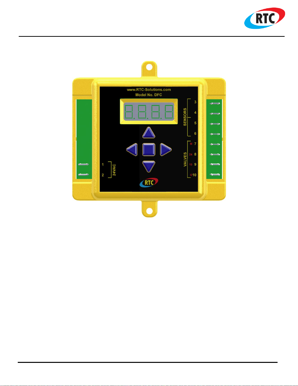
Model No. DFC
DFC
Direct Fired Control
DIGITAL ENHANCED GAS FIRED MODULATING CONTROL
This manual covers the following product(s):
Table of Contents
Overview ............................................................................................................................................................................ 2
Normal Operation ................................................................................................................................................................ 2
Programming ...................................................................................................................................................................... 3
Features ............................................................................................................................................................................. 3
Valve Connections ............................................................................................................................................................... 4
Menu Map ........................................................................................................................................................................... 5
Installation ......................................................................................................................................................................... 6
Specifications ...................................................................................................................................................................... 6
DOC# T0008 2.2.2015 DFC O&M 1
Page 2
Ph. (877) 351-4702
www.RTC-Solutions.com
4380 Oakes Road, Suite 804
Fax (919) 845-8102
Email: info@RTC-Solutions.com
Davie, FL 33314
Overview
ENT
DN
UP
DN
UP
Figure 2: DFC Keys
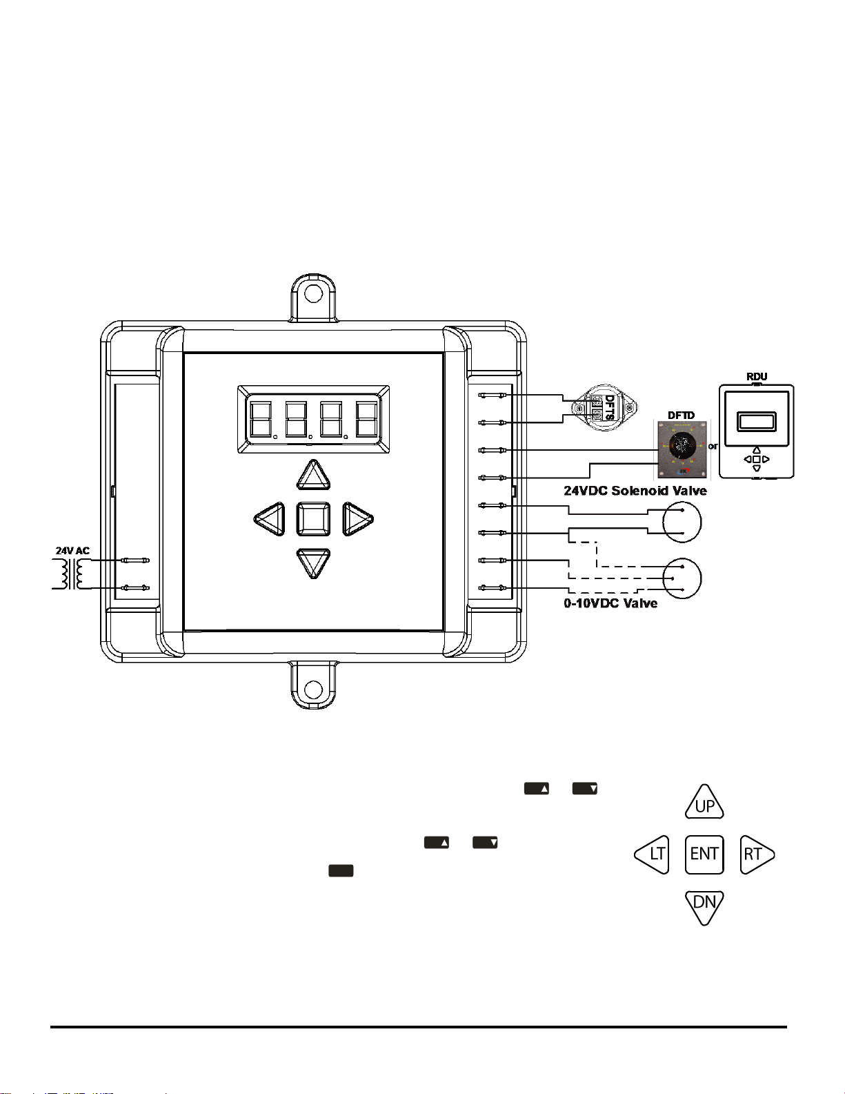
Figure 1: DFC Schematic Layout
The Direct Fired Control (DFC) is a digital gas fired heating control. The control has a simple five button interface with a
four digit LED display. All programmable parameters can be accessed through the user menu with the five button
interface. The DFC’s setpoint temperature sensing operation ranges from 40°F (4°C) to 250°F (121°C). There is a
temperature sensor input that connects to provide a discharge temperature. The setpoint may be adjusted by the controls
internal menu settings or by an external remote, such as the DFTD and RDU. There is a combination of two modulating
outputs that will power either a 0-24V DC solenoid or a 0-10V DC actuated valve. User parameters are stored in non-
volatile memory, and are retained even during a power outage. Also, the DFC is powered by 24V AC.
Normal Operation
The DFC will always display the current discharge air temperature. Press the or
key to change the discharge setpoint temperature. Once the key is pressed, the LED will
display the text for the current setpoint temperature. Use the or key in order to set
a new discharge temperature. Then press the key to save the changes made. If a key is
not pressed for 10 seconds, the DFC will exit without saving. When adjusting the setpoint
range, the setpoint cannot surpass the set Low and High values. For instance, if Low
(“SPLo”) is set to 80°F and High (“SPhi”) is set to 150°F, the setpoint is adjustable between
80°F to 150°F.
DOC# T0008 2.2.2015 DFC O&M 2
Page 3

Ph. (877) 351-4702
www.RTC-Solutions.com
4380 Oakes Road, Suite 804
Fax (919) 845-8102
Email: info@RTC-Solutions.com
Davie, FL 33314
Programming
ENT
DN
UP
ENT
ENT
LT
ENT
DN
UP
RT
DN
UP
ENT
Connection for 0-24V DC use terminals 7 and 8
Connection for 0-10V DC use terminals 8, 9, and 10
1 24 VAC
2 24 VAC
3 DFTS
4 DFTS
5 DFTD or RDU
6 DFTD or RDU
7 PW M For Sol enoi d Valve
8 24 VDC Valve Output
9 0-1 0VDC Valve Output
10 Va l ve Ground
Figure 3: DFC Modulating Output
Terminals
Please refer to the “DFC Menu Map” on Page 4 for programming in program mode. To enter program mode, hold the
key down for 3 seconds until “SPLo” is displayed. Use the and keys to navigate to the desired menu
parameter as shown in column 1. To edit a menu parameter, press the key once on the desired parameter. The
current value of that parameter will be displayed as shown in column 2. Use the and keys again to edit the
parameters for column 2. Press the key to save the changes made or the key to cancel without saving and return
to column 1. If a key is not pressed for 10 seconds or the key is held for 3 seconds while in program mode, the
control will return to normal mode.
Features
Alarms:
Error messages on the DFC will be scrolled across the display with a detailed message. This will allow users to realize the
issue in order to resolve the error faster. The list of errors and their meanings are below.
1. “dFtS oPEn” – There is no Discharge Temperature Sensor connected to the DFC. Therefore, no discharge
temperature reading can be made.
2. “dFtd oPEn” – The user has the Remote (“rEtd”) parameter on the DFC enabled, but no external control is found
to take a reading.
3. “dFts ShortEd” – There is a short in the connection of the Discharge Temperature Sensor.
4. “dFtd ShortEd” – The user has the Remote (“rEtd”) parameter on the DFC enabled and there is a short in the
connection.
To resolve an issue check the wiring connections. Please refer to “Installation” on page 5 for proper terminal connections.
Password:
When trying to access program mode, if the DFC is password protected the display will show “PASS”. Otherwise the
display will show “SPLo”, which is the start of program mode. If password protected no menu settings may be altered
until the correct password is entered. In order to enter the password press the key while “PASS” is displayed and
use the and keys to set the DFC to the factory set password (21). Once on the number 21, press the key
again to access program mode. If the wrong password is entered then the DFC will return to normal mode.
Modulating Valve Outputs:
The DFC has the ability to power either a 24V DC or a 10V DC modulating valve. Only one valve at a time may be connected.
DOC# T0008 2.2.2015 DFC O&M 3
Page 4

Ph. (877) 351-4702
www.RTC-Solutions.com
4380 Oakes Road, Suite 804
Fax (919) 845-8102
Email: info@RTC-Solutions.com
Davie, FL 33314
Valve Connections
DFC
Solenoid
ACT-4.0
Belimo
Siemens
Term 7: PWM
PWM
Term 8: 24VDC
24VDC
Red: 24VDC
2: 24VDC
Red: 24VAC
Term 9: 0-10V Output
Green: 0-10V Input
3: 2-10V Input
Gray: 0-10V Input
Term 10: Ground
Blue: Ground
1: Ground
Black: Ground
DOC# T0008 2.2.2015 DFC O&M 4
Page 5

Ph. (877) 351-4702
www.RTC-Solutions.com
4380 Oakes Road, Suite 804
Fax (919) 845-8102
Email: info@RTC-Solutions.com
Davie, FL 33314
Menu Map
vEr
What you want to do
What you see
What it means
DFC Menu Map
Column 1
Column 2
Set the lowest the user can adjust the
temperature to in normal mode for setpoint.
Adjust the discharge setpoint.
Set the Valve Maximum Output percentage.
Valve Reverse Output.
Select the desired aggression/speed of the PID
curve for the valve (Standard, Low, or High).
Low (SPLo) can be set from 40°F - 240 °F and must be
at least 10°F less than the High. High (SPhi) can set be
from 50°F - 250°F and must be at least 10°F greater
than the Low. These will limit how far the user can
change the temperature outside of programming
mode.
Setpoint (SP) may be adjusted within the menu map or
on the main screen with the up and down arrows, then
pressing enter to save the selected setpoint.
When adjusting the discharge setpoint temperature
above the outside air it will result in turning the
burner on and modulate the system at that specified
setpoint.
Column 1 shows the menu parameters
Arrow Keys:
Up and Down: to navigate or adjust a menu parameter
Right: to access column 2 for editing a parameter
Left: to return to column 1 without saving a parameter
Enter: to return to column 1 with saving a parameter
Column 2 shows the factory set defaults for each
parameter. Temperature defaults are shown in °F.
Figure 4: Menu Map
PASS
100
dAbL
EnAb
1.01.1
vdEL
vLo
10
0
LT
RT
SPhi
SP
rEtd
9 0
7 5
dAbL
EnAb
SPLo
40
DN
ENT
UP
Set the highest the user can adjust the
temperature to in normal mode for setpoint.
Enables or Disables the use of an external remote
control for adjusting the setpoint.
Set the Valve Startup Delay from 0 to 30 seconds.
Set the Valve Minimum Output percentage.
Remote (rEtd) allows the user to use the DFC’s built-in
interface when disabled (dAbL) or an external remote
control when enabled (EnAb) in order to adjust the
setpoint.
dAbL
vhi
Lo
EnAb
Std
hi
Pid
rEvo
° C 0 ° F
toFS
ForC
Set a temperature offset. For example, to correct
for duct losses or sensor calibration errors.
Set the control to convert the temperature to
display either °F or °C.
The password may either be enabled or disabled.
View the software version number.
Valve Minimum Output (vLo), controls the percentage
the valve will operate when in the closed position
Valve Maximum Output (vhi), controls the percentage
the valve will operate when in the open position
Valve Reverse Output (rEvo), causes the valve voltage
output to be inverted. For example, if the discharge
temperature increases then the valve voltage output
will decrease
DN
UP
DOC# T0008 2.2.2015 DFC O&M 5
Page 6

Ph. (877) 351-4702
www.RTC-Solutions.com
4380 Oakes Road, Suite 804
Fax (919) 845-8102
Email: info@RTC-Solutions.com
Davie, FL 33314
Installation
Figure 5: DFC Front Panel
Figure 6: DFC Side view
Power Requirements
Current Rating 24V Output
DFC Ambient Temperature Limits
Operating
Accuracy
24V AC
1A
40-250°F (4-48°C)
+/-3°F (1°C)
4.84
4.93
4.50
1.527
Figure 7: DFC Terminal
Number Layout
1 24VAC
2 24VAC
3 DFTS
4 DFTS
5 DFTD or RDU
6 DFTD or RDU
7 PW M For Sol enoi d Va l ve
8 24VDC Va lve Output
9 0-10 VDC Val ve Output
10 Va lve Ground
Wiring for the DFC is convenient for the user with easy access to all terminal connections.
Specifications
***All dimensions are in inches ***
DOC# T0008 2.2.2015 DFC O&M 6
 Loading...