

Page 1

AP21 Series T ime Switch
Operation/Service Manual
(use this manual for Ver 3.02 and higher)
“Helping Kids Get To School Since 1987”
RTC Manufacturing, Inc.
1016 Enterprise Place * Arlington, TX 76001
www.rtc-traffic.com
(817) 860-1217
Page 2

AP21 SERIES TIME SWITCH
OPERA TION/SERVICE MANUAL
Table of Contents 2
A. Introduction 3
B. Specifications
Programming Capabilities 3
Electrical 3
Power Fail Backup 4
Accuracy 4
Physical 4
C. Wiring 4
D. Description of Display and Keyboard
Alpha-Numeric Display 5
Keyboard 5
E. Programming Instructions
AP21 Cursor 6
Auto Prompt Display 6
Entering Data 6
Quick Reference Program Guide 7
Program Guide Key 8
Special Code 8
Time Switch Keys 8
Programming Procedures for:
TIME 8
DATE 9
DAY 9
DST 9
BASIC Program Steps 10
ANNUAL Program Steps 10
SLEEP MODE 11
PULSE 11
MANUAL Operation 12
SECONDS Display 12
PROGRAM TRANSFER 12
F. Warranty 12
G. Service 12
H. Theory of Operation 13
I. Schematic & Part List 13
2
Page 3

AP21 SERIES OPERATOR’S MANUAL
OPERATIONS/SERVICE MANUAL
A. INTRODUCTION
The AP21 is an single circuit, calendar programmable solid state time switch. It is used for switching electric circuits
according to pre-set time and date program. The AP21 AUT O PROMPTING alpha-numeric display makes programming fast
and simple. It is designed to control zone flashers, time-of-day flash, or any other traffic application where holiday skip is
desired. The output relay is rated at 120 VAC, 15 amps resistive load. The output can be programmed for momentary
operation such as required for ringing bells in school, churches or industrial facilities. The relay output can also be disabled by
SLEEP MODE function to allow time switch to maintain data without operating the relay.
B. SPECIFICATION
PROGRAMMING CAP ABILITIES
1. Auto Prompting Display - Provides display information to guide the operator during programming. From a cold start it will
prompt the operator in setting the time through setting the basic program steps.
2. 16 Program S teps - Each step can be programmed for a specific day of the week, for Monday through Friday only , for
Saturday and Sunday only , or for every day of the week.
3. 10 Skip Plans - Each skip plan has a starting and ending date that prevents the output relay from activating. This
feature can be used to skip a specific day or a group of consecutive days.
4. Programmable Daylight Saving T ime Adjustment - The AP21 can be programmed to automatically adjust its time for
daylight savings time changes according to U.S. law, even if the law changes.
5. Automatic Leap Year Compensation.
6. Manual Override - The output relay can be manually energized or de-energized from the keyboard. The manual
override remains in effect until the next programmed step occurs.
7. Sleep Mode - Deactivates relay output while maintaining all timing data during summer vacation.
8. Pulse Output - The output can be programmed to operate as constant contact or a momentary contact programmable
from 1 to 99 seconds.
9. Program Transfer - This option allows the operator to program an AP21 and download that program to another AP21 with
the use of a simple unit-to-unit transfer cable.
ELECTRICAL
Power Requirements - 95V AC to 135VAC, 60HZ., 3 V A maximum.
10.5VDC to 14.3VDC less than 1 Watt through full
range of supply volt age (0.2 to 0.58 average)
Outputs - AP21, SPDT relay rated at 15 AMP resistive at 120VAC.
Wiring - T erminal block can accommodate #10 to #24 AWG wire.
3
Page 4
POWER FAIL BACKUP
Program and time keeping is maintained for 48 hours on a rechargeable capacitive backup system in the event of a power
failure. The output and display are disabled during backup. The AP21 resumes normal operation when power is restored.
ACCURACY
Time Keeping - Synchronous with the AC power line and 4 PPM on DC power. During a power failure it is quartz crystal
controlled with an accuracy of +/-.005% throughout its full temperature range.
Programmed Events - On/Off events are programmable with a one minute resolution and occur at the zero second of that
minute.
PHYSICAL
3.7"W x 8.0"H x 1.55"D
Weight - Approximately 2 lbs.
Mounting - Mounting hole provided (AP21/AP21T).
Operating Temperature Range - -30 to +74 C.
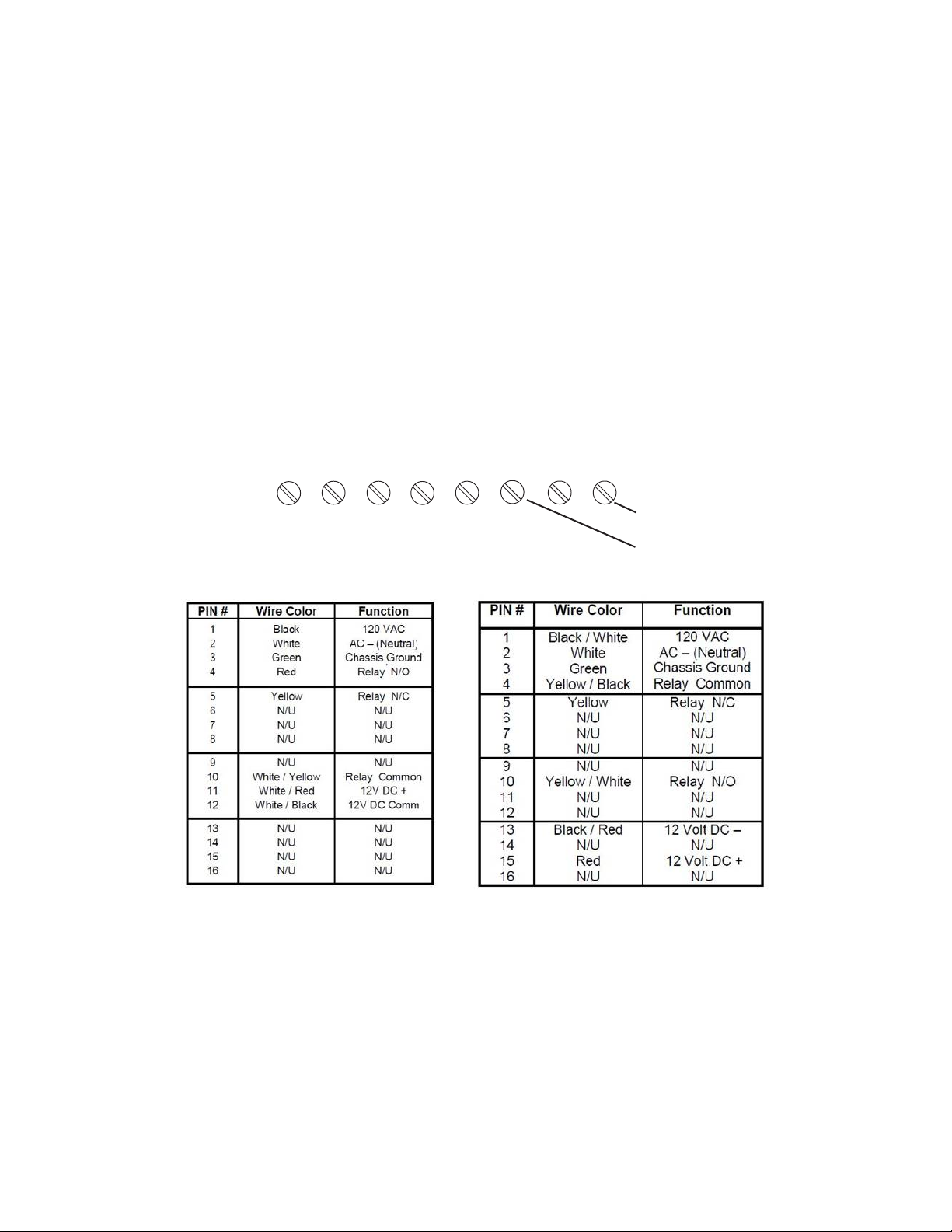
C. WIRING
Remove power before wiring connection. Observe all safety precautions.
AP21
AC-
AC+ COM
GND
N/O-12V+12V
N/C
Terminal Block
Relay moveable (in)
Relay N/O (out)
TXDOT Wiring AP2T/CPR
Standard Wiring AP21T/CPR
AP21TR OCT AL BASE MOUNT PIN OUT (Discontinued product)
T o install the AP21TR requires an eight pin oct al base Potter and Brumfield #27E122 or equal. Mount this base in a suitable
location and wire the terminals of the base as follows:
AC Version DC Version
1. Relay Common 1. Relay Common
2. Line 2.
3. Relay normally open 3. Relay normally open
4. Relay normally closed 4. Relay normally Closed
5. 5.
6. 6. -12VDC
7. Neutral 7.
8. 8. +12VDC
4
Page 5

D. DESCRIPTION OF DISPLAY AND KEYBOARD
1. ALPHA-NUMERIC DISPLAY – Used for displaying time, day, date, output status and for
displaying information during programming or reviewing stored programs.
2. KEYBOARD – Many of the AP21 keys serve multiple functions. Those keys are clearly labeled
with their functions printed adjacent to the key . They cannot be used incorrectly as the display will AUTO
PROMPT the user as to which key to press.
AM/ON (#1) KEY – Used for setting time to AM when in the time set or programming modes. Also used
for setting output to ON or OFF when in the programming mode. Also used for setting the output to ON
manually.
PM (#2) KEY – Used for setting the time to PM when in the time set or programming modes.
TIME (#3) KEY – Used for entering the set time mode.
ANNUAL (A) KEY – Used for entering the annual programming mode and for stepping through the stored
annual programs for review. The annual programs contain the skip plans in calendar schedule form.
BASIC (B) KEY – Used for entering the basic programming mode and for stepping through the stored
basic programs for review. The basic programs contain the daily timed events instructions.
CLEAR (C) KEY – Used for clearing all annual skip plans and basic program steps.
DATE (D) KEY – Used for entering the set date mode for entering date or reviewing the date.
EXIT (#) KEY – Used for exiting the set time, set date, or program mode.
OFF (#0) KEY – Used for setting the output to OFF when in the programming mode. Also used for
setting the output to OFF manually.
STEP/ENTER (*) KEY – Used for entering all commands and for stepping through the set time, set date
or program data entry.
DST (#7) KEY – Used for entering or changing the daylight savings time program.
DAY (#4) KEY – Used for setting the current day of the week.
(#5) KEY (PULSE) – Used for programming the output relay/s for steady or pulse operation.
5
Page 6

E. PROGRAMMING INSTRUCTIONS
THE AP21 CURSOR - On many of the AP21 display screens you will see a flashing square character called the cursor . The
cursor indicates that you may now enter or change the data at that position of the display .
AUTO PROMPT DISPLAY - On a cold start with a discharged back-up capacitor, the AP21 will automatically prompt the
operator through the programming procedure. The operator simply has to follow the display and enter the appropriate data as
the cursor advances through the program entries. Y ou may exit this sequence if desired by pressing the EXIT (#) key and the
unit will default to the time display mode. From the time display mode, you may enter any of the set time, date, or program
modes manually .
ENTERING DA TA - From the cursor , you enter the appropriate data and press the ENTER (*) key . The cursor will automatically
advance to the next position. If the data at the cursor is correct, simply press the ENTER (*) key to advance the cursor . The
AP21 will not allow you to enter an invalid number (i.e., the unit will not accept the number 13 for a month entry). The cursor
will remain in its position until a valid entry is made, so keep pressing the keys until you see the correct number at the cursor
and then press the ENTER (*) key .
6
Page 7

AP21 QUICK REFERENCE PROGRAM GUIDE
NOTE: The display of the AP21 will automatically blank after about 5 minutes of keyboard inactivity, simply press any key
to reactivate the display .
St art from the time display mode:
TIME:Press the TIME (3) key, press ENTER (*), and enter the
time as follows:
HH * MM * AM/PM *
(enter) (enter) (enter)
DATE: Press the DATE (D) key, press ENTER (*), and enter the
date as follows:
MM * DD * YY *
DAY: Press the DA Y (4) key, press ENTER (*), and enter the
day of the week as follows:
Day-of-week *
(press the DA Y (4) key to advance the day)
DST: Press the DST (7) key, press ENTER (*), and enter the
spring and fall Daylight Savings Time as follows:
S DST: MM * SUN *
F DST: MM * SUN *
Current U.S. law: Spring = Month 3, Sunday 2
Fall = Month 11, Sunday 1
BASIC: Press the BASIC (B) key, press ENTER (*), key in
the step number, press ENTER (*), and enter the program
step information as follows:
Day/s * HH * MM * AM/PM * ON/OFF *
ANNUAL: Press the ANNUAL (A) key, press ENTER (*), key in
the skip number, press ENTER (*), and enter the
annual skip plan program as follows:
START: MM * DD * YY *
END: MM * DD * YY *
Note: Single Day skip- Start & End date are the same.
MANUAL: To manually operate the output relay:
To turn on: 1 *
To turn off: 0 *
7
Page 8

SECONDS: Key in 33 and press the ENTER (*) key . Press the
EXIT (#) key to go back to normal time display.
TRANSFER: Key in “78” on the AP21 you wish to transfer from, press ENTER (*).
Connect the transfer cable (RTC Part # 91107), press ENTER (*).
CLEAR: Press the clear (C) key, press ENTER (*).
Press ANNUAL (A) key to clear all of the Annual programs.
Press BASIC (B) clear all of the Basic programs.
Key: * = enter
WDY = Mon thru Fri MM = month of the year
EDY = every day of the week DD = day of the month
WND = Sat & Sun only YY = year
HH = hour of the day
MM = minute of the hour
SUN = the Sunday of the month for DST change
1 = first Sunday
2 = second Sunday
3 = third Sunday
4 = fourth Sunday
L = last Sunday
Special Codes: 0 = Manual operation - OFF
1 = Manual operation - ON
7 = DST (daylight saving time change)
45= Sleep Mode (Disables output relay)
77 = Clear all data for reprogramming
78 = Program transfer between AP21 unit s
99 = Software version
88 = Prevents the screen from blanking
88 again allows the screen to blank
(HH : MM) - Colon flashing= Display Blanking, Colon steady= Display “ON” continuous
Time Switch Keys:
1 = AM and ON
2 = PM
3 = TIME (time-of-day)
4 = DA Y (day-of-week)
5 = PULSE (pulse or steady output/s)
7 = DST (Daylight Savings T ime)
0 = OFF (relay off)
A = ANNUAL (programs)
B = BASIC (programs)
C = CLEAR (clear all annual or basic programs)
D = DA TE (month, day, year)
# = EXIT (exit to the time display mode)
* = ENTER (enter the data at the cursor)
Procedure for reviewing or changing the TIME:
· Start from the time display mode
· Press the TIME (#3) key
8
Page 9

· Press the ENTER (*) key
· Press the ENTER (*) key if the hour displayed is correct or, key
in the correct hour then press the ENTER (*) key ,
the cursor will advance to the minute position
· Press the ENTER (*) key if the minute displayed is correct or, key
in the correct minute then press the ENTER (*) key ,
the cursor will advance to the AM/PM position
· Press the ENTER (*) key if the AM/PM displayed is correct or, key
in the correct AM/PM then press the ENTER (*) key,
the new time will begin and the display will return to the time display mode
Procedure for reviewing or changing the DATE:
· Start from the time display mode
· Press the DATE (D) key
· Press the ENTER (*) key if the month displayed is correct or, key
in the correct month then press the ENTER (*) key ,
the cursor will advance to the day position
· Press the ENTER (*) key if the day displayed is correct or, key
in the correct day then press the ENTER (*) key ,
the cursor will advance to the year position
· Press the ENTER (*) key if the year displayed is correct or, key
in the correct year then press the ENTER (*) key ,
the display will return to the time display mode
Procedure for reviewing or changing the DAY:
· Start from the time display mode
· Press the DAY (#4) key
· Press the ENTER (*) key
· Press the ENTER (*) key if the day displayed is correct or,
advance to the correct day by pressing the DA Y (#4) key,
Press the ENTER (*) key , the display will return to the time display mode
Procedure for reviewing or changing the DST (Daylight Saving Time):
· Start from the time display mode
· Press the DST (#7) key
· Press the ENTER (*) key, the SPRING DST display will show
· Press the ENTER (*) key if the month displayed is correct or, key
in the correct month then press the ENTER (*) key ,
(NOTE: key in 00 (zero,zero) to defeat the DST feature)
the cursor will advance to the Sunday position
· Press the ENTER (*) key if the Sunday displayed is correct or,
key in the correct Sunday then press the ENTER (*) key ,
the display will advance to the FALL DST display
· Press the ENTER (*) key if the month displayed is correct or, key
in the correct month then press the ENTER (*) key ,
the cursor will advance to the Sunday position
· Press the ENTER (*) key of the Sunday displayed is correct or,
key in the correct Sunday then press ENTER (*) key ,
the display will return to the time display mode
9
Page 10

Procedure for entering or changing the BASIC program steps:
· Start from the time display mode
· Press the BASIC (B) key
· Press the ENTER (*) key
· Key in specific program step number to be changed,
then press the ENTER (*) key
· Press the ENTER (*) key if the day/s displayed is correct or,
advance to the correct day/s by pressing the DA Y (#4) key,
then press the ENTER (*) key ,
the cursor will advance to the hour position
· Press the ENTER (*) key if the hour displayed is correct or, key
in the correct hour then press the ENTER (*) key ,
the cursor will advance to the AM/PM position
· Press the ENTER (*) key if the AM/PM displayed is correct or, key
in the correct AM/PM then press the ENTER (*) key,
the display will advance to the ON/OFF position
· Press the ENTER (*) key if the ON/OFF displayed is correct or,
toggle the ON or OFF then press the ENTER (*) key ,
the cursor will advance to the next program step number
· Repeat the programming process or press the EXIT (#) key
to return to the time display mode
Procedure for reviewing the BASIC program steps:
· Start from the time display mode
· Press the BASIC (B) key
· Press the ENTER (*) key
· Press the BASIC (B) key to advance through the basic program steps
· Press the EXIT (#) key to escape to the time display mode
Procedure for clearing a specific BASIC program step:
· Start from the time display mode
· Press the BASIC (B) key
· Press the ENTER (*) key
· Key in the step number to be cleared then press the ENTER (*) key
· Press the ENTER (*) key to advance the cursor to the hour
· Key in 00 (zero, zero) for the hour then press the ENTER (*) key,
· the program step is cleared and the display returns to step 00.
· Key in another step number to be cleared or press EXIT (#) to
return to the time display mode
Procedure for entering or changing the ANNUAL skip plan program steps:
· Start from the time display mode
· Press the ANNUAL (A) key
· Press the ENTER (*) key
· Key in specific skip plan number to be changed,
then press ENTER (*) key , the START date (MM-DD-YY) will be displayed
· Press the ENTER (*) key if the month displayed is correct or, key
in the correct month then press the ENTER (*) key ,
the cursor will advance to the day position
· Press the ENTER (*) key if the day displayed is correct or, key
10
Page 11

in the correct day then press the ENTER (*) key ,
the cursor will advance to the year position
· Press the ENTER (*) key if the year displayed is correct or, key
in the correct year then press the ENTER (*) key ,
the display will advance to the END date (MM-DD-YY)
· Press the ENTER (*) key if the month displayed is correct or,
key in the correct month then press the ENTER (*)key ,
the cursor will advance to the day position
· Press the ENTER (*) key if the day displayed is correct or, key
in the correct day then press the ENTER (*) key ,
the cursor will advance to the year position
· Press the ENTER (*) key if the year displayed is correct or, key
in the correct year then press the ENTER (*) key ,
the display will advance to the next skip plan number
· Repeat the programming process or press the EXIT (#) key
to return to the time display mode
Procedure for reviewing the ANNUAL skip plan program steps:
· Start from the time display mode
· Press the ANNUAL (A) key
· Press the ENTER (*) key
· Press the ANNUAL (A) key to advance thru the annual skip plan
program steps
· Press the EXIT (#) key to escape to the time display mode
Procedure for clearing all of the ANNUAL programs:
· Start from the time display mode
· Press the CLEAR (C) key
· Press the ENTER (*) key
· Press the ANNUAL (A) key to clear all annual programs
· The display returns to the time display mode
Procedure for clearing a specific ANNUAL program:
· Start from the time display mode
· Press the ANNUAL (A) key
· Press the ENTER (*) key
· Key in the skip number to be cleared then press the ENTER (*) key
· Key in 00 (zero, zero) for the month then press the ENTER (*) key,
the skip plan is cleared and the display returns to skip 00.
· Key in another skip number to be cleared or,
press the EXIT (#) key to return to the time display mode
Procedure for activating SLEEP MODE:
. St art from the time display mode
. Key in 45 and press ENTER (*), SLEEP MODE will be displayed
Procedure for deactivating SLEEP MODE:
. Start from the SLEEP MODE display
. Key in 45 and press ENTER (*) key to remove sleep mode
Procedure for reviewing or changing the PULSE:
· Start from the time display mode
· Press the #5 key
· Press the ENTER (*) key
· Press the ENTER (*) key if the pulse displayed is correct or,
11
Page 12

key in the correct pulse then press the ENTER (*) key ,
(0 = steady , 1 to 9 seconds = pulse)
the display will return to the time display mode
Procedure for MANUAL operation of the output relay:
ON · Start from the time display mode
· Press the #1 key
· Press the ENTER (*) key, the output relay is turned on
· The display returns to the time display mode
OFF · St art from the time display mode
· Press the #0 key
· Press the ENTER (*) key, the output relay is turned off
· The display returns to the time display mode
Procedure for displaying SECONDS in the time display:
· Start from the time display mode
· Key in 33 and press ENTER (*), the seconds display will be shown
· Press the EXIT (#) key to return to the normal time display mode
Procedure for program transfer operation:
· Start from the time display mode
· Key in 78 on the AP21 you wish to transfer from, press ENTER (*)
· Connect a transfer cable to both AP21 units
· Press ENTER (*) on the AP21 you wish to transfer the program from
· The display on both units returns to the time display mode
F. WARRANTY
RTC Manufacturing, Inc. hereby warrants that, provided the time switch was properly installed, operated and maintained by
the user, RTC will at its option, either replace or repair without charges any time switch found to be defective in materials
and/or workmanship for two (2) years from the date of shipment.
Products returned for warranty must be shipped freight prepaid. RTC will pay the shipping charges for repaired products
returned to the customer via regular surface freight. Overnight delivery must be requested in advance and will be billed to
the customer.
In no event shall RTC Manufacturing, Inc. be liable for any injury , loss or damage, whether direct, consequential or incidental
to persons or property arising out of purchaser’s ability or inability to use the time switch.
G. SERVICE
It is recommended that all service for the AP21 be performed by the factory or by a factory authorized service represent ative.
If you repair your AP21 time switches without factory support, please note the following:
CAUTION: Before removing or replacing any IC1 or IC2, the 1 FD super capacitor must be totally discharged to
avoid damage. On the left side of the printed circuit assembly, there are two test points. One is ground and the
other is the super capacitor connection. Use a clip lead to short these test points together to discharge the super
capacitor. It is recommended that the clip lead be left in place until the repair is completed.
12
Page 13

RTC Manufacturing, Inc. is committed to provide ongoing service support for time switches in or out of warranty. Please
ship your repairs freight prepaid to the dealer in your area:
OR
RTC Manufacturing, Inc.
1016 Enterprise Place
Arlington, TX 76001
If the customer/end user ships directly to RTC, shipping charges will be paid by RTC for repaired products returned to the
customer/end user via regular surface freight. Overnight delivery must be requested in advance and will be billed to the
customer/end user.
H.
THEORY OF OPERATION
The AP21 is a microprocessor based device. Because of the large scale integrated circuit s used, there are only three (3) IC’s
that make up the time switch.
IC1 is a 6805 type microprocessor with built-in RAM and ROM. The built-in RAM is used for storing the time, date and program
information. The built-in ROM contains the AP21 operating software (approximately 4 k-bytes). The software of the AP21 time
switch is copyrighted. Reproductions of any kind are strictly prohibited by law.
IC2 is the real time clock. This circuitry is used only during power failures to keep time until power returns.
I. Schematics and Parts List are available directly from RTC.
“Helping Kids Get To School Since 1987”
RTC Manufacturing, Inc.
1016 Enterprise Place * Arlington, TX 76001
www.rtc-traffic.com
(817) 860-1217
13
 Loading...