

Page 1
English
MODEL RTA - 4805L
Thanks for purchasing one of our products.
Please read carefully the assembly instructions before the installation.
Please save this manual for future reference.
MODEL RTA-4805L
Page 2
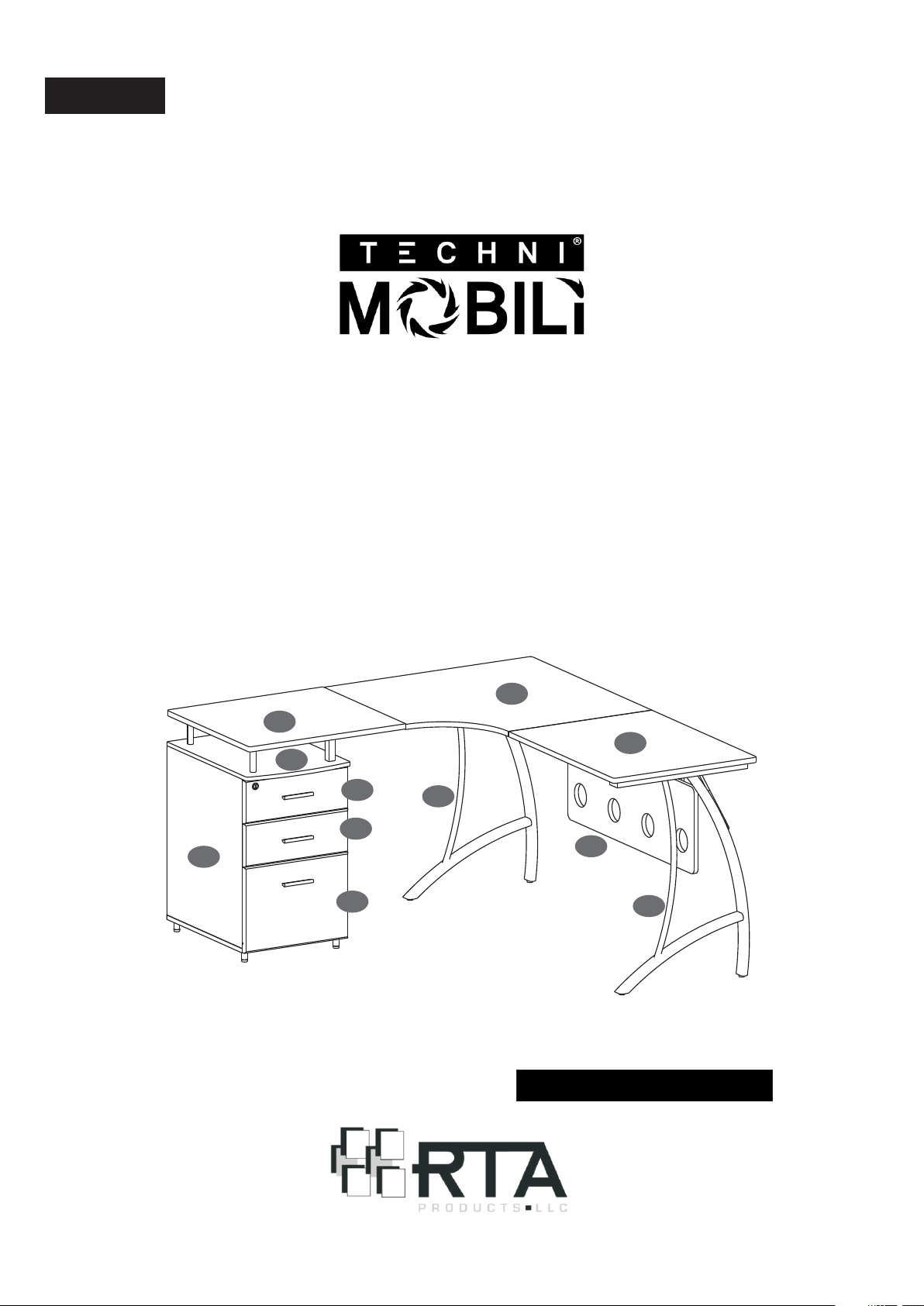
Spanish
INSTRUCCIONES DE ENSAMBLAJE.
MODELO RTA - 4805L
Gracias por comprar uno de nuestros productos.
Por favor lea cuidadosamente las instrucciones de ensamblaje antes de
instalar la unidad.
Por favor guarde este manual para referencias futuras.
19
16
20
7
23
24
1
28
8
40
9
MODELO RTA-4805L
Page 3
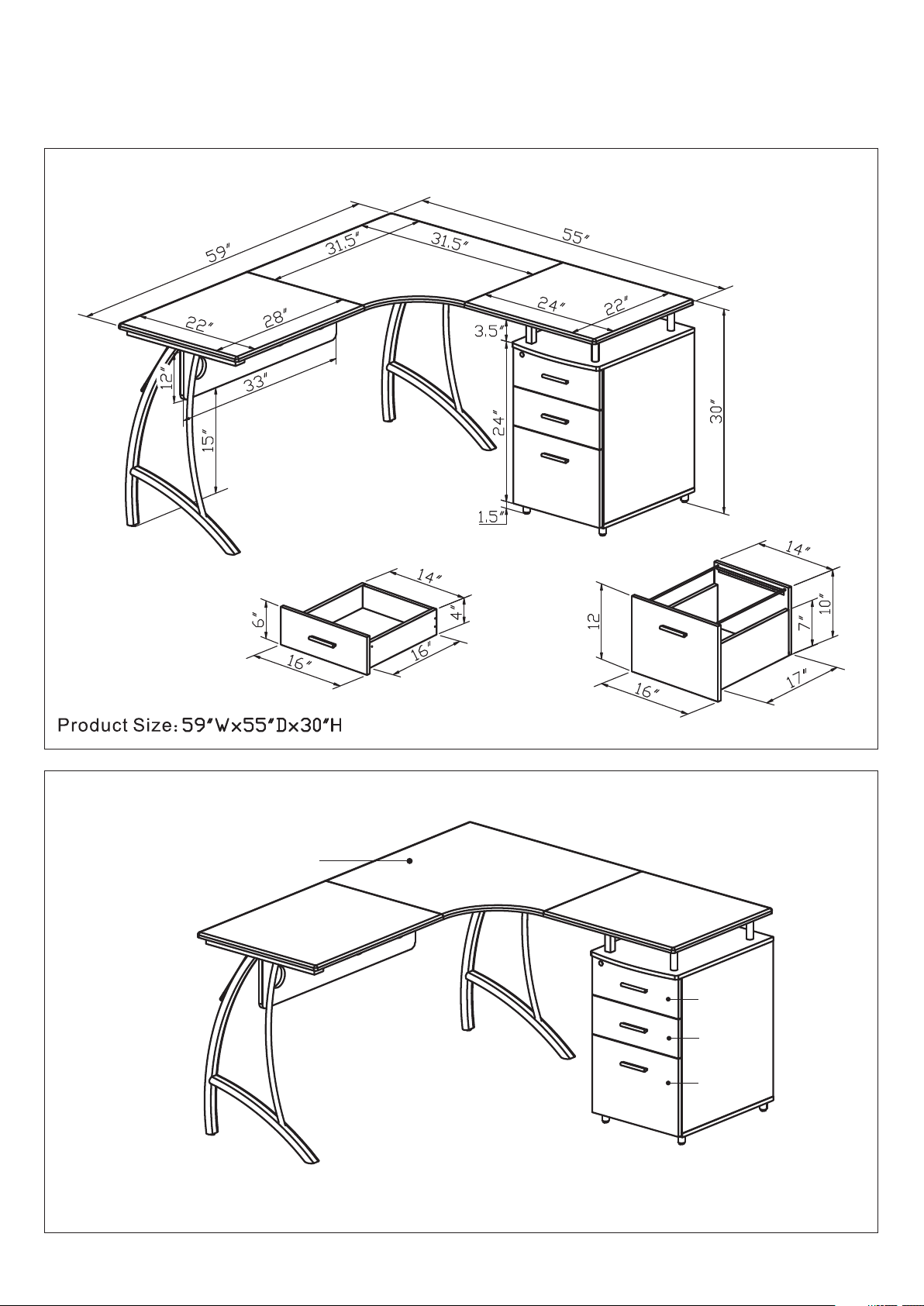
RTA-4805L
DIMENSIONS
MAXIMUM WEIGHT CAPACITIES
TABLETO P 10 0Lbs
DO NOT ex ceed this limit
Please use care an d good judgement
when placing obj ects on wood surface
TOP DRAWER 22 Lb s
MIDD LE D RAWE R 22 Lbs
BOTTOM DRAWER 22Lb s
Page 4

RTA-4805L
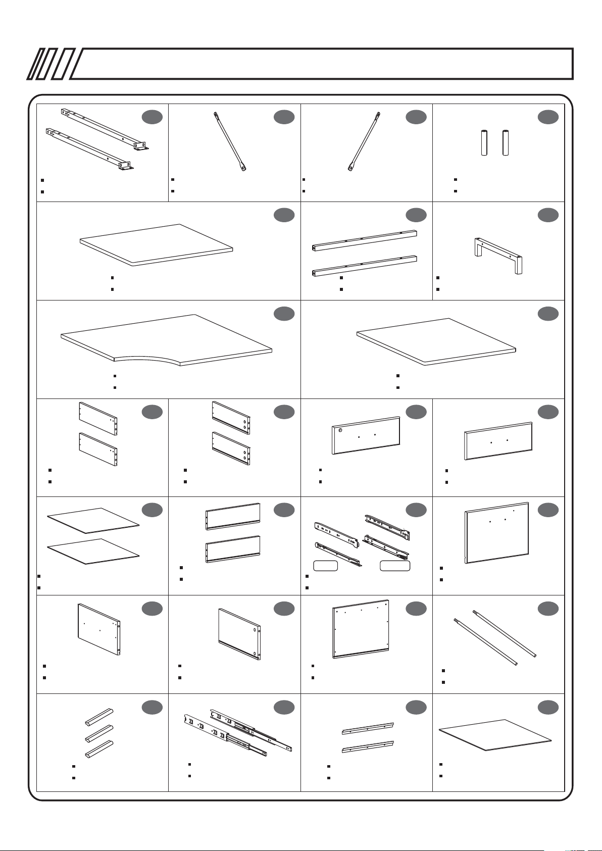
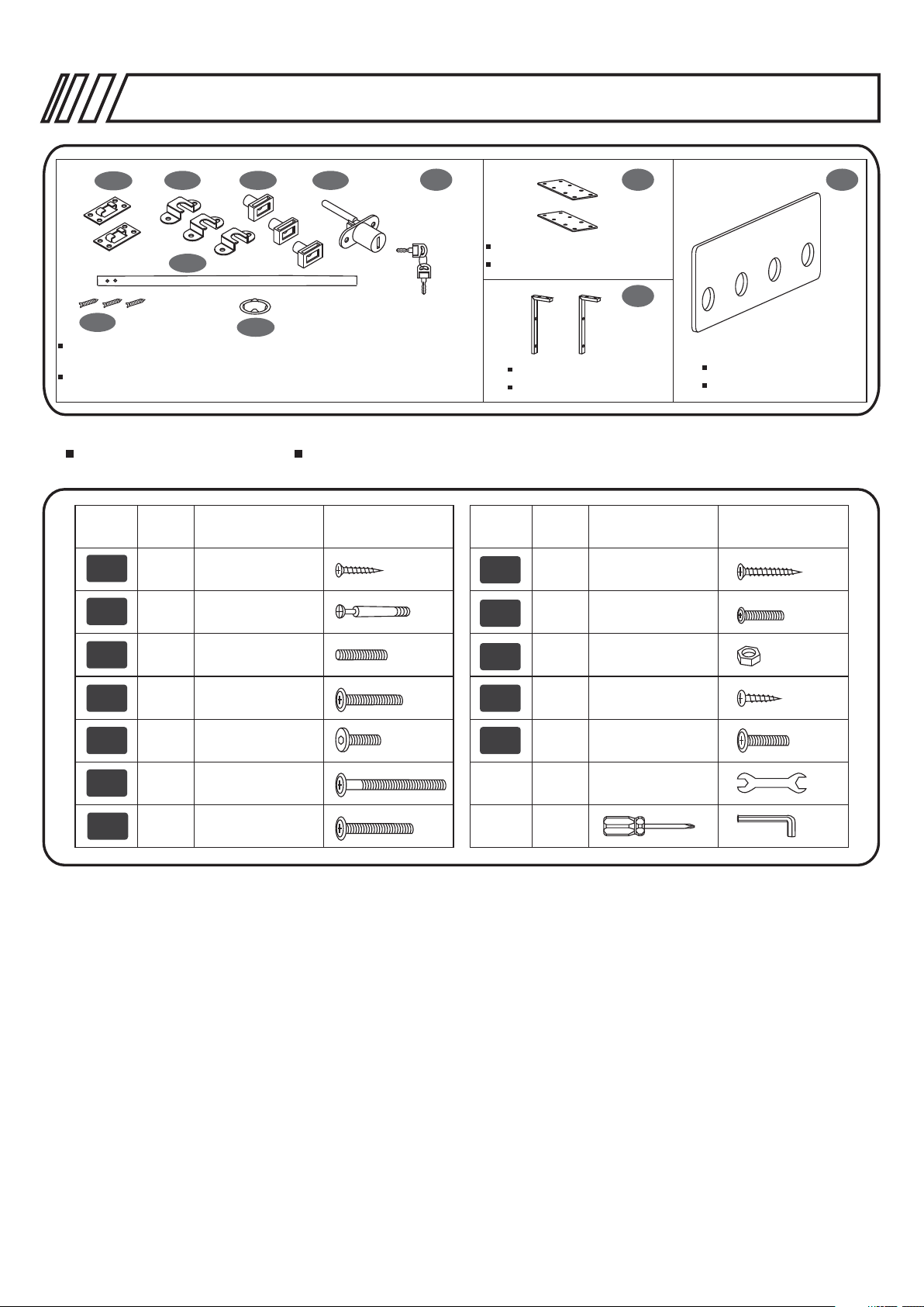
PARTS LIST LISTA DE PIEZAS
19
16
7
P.4
20
23
8
24
1
28
1 4
2
40
9
3
Bottom Panel
Panel inferior
5
Left Panel
Panel izquierdo
6
X8Pcs
Studs
Topes
7
Cabinet Top Panel
Panel superior del ca binete
Right Panel
Panel derecho
Left Frame
Estructura izquierda
X4Pcs
Back Panel
Panel posterior
8
9
Bottom Support Tube
Tubo de soporte inferior
10
Left Front Connect Tube
Tub o frontal d e co nexión
izqu ie rdo
11
Right Frame
Estructura derecha
Left Back Connect Tube
Tub o posteri or d e conexió n
dere ch o
Page 5
RTA-4805L
P.5
X2Pcs
Right Connect Tube
Tubo de conexión derecho
Small Table Panel
Panel de mesa pequeño
Corner Table Panel
Panel de mesa esquine ro
12
13
Right Support Structure
Estructura de soporte derecha
16
19
14
Left Support Structure
Estructura de soporte izquierd a
17
Long Tube
Tubo largo
X2Pcs
Big Table Panel
Panel de mesa grande
15
X2Pcs
Top Support Tube
Tubo de soporte superior
18
Support Frame
Estructura de soporte superior
20
21
X2Pcs
Small Drawer Left Panel
Panel izquierdo de ga veta
pequeña
25
X2Pcs
Small Drawer Bottom Panel
Panel inferior de gaveta inferio r
29
File Drawer Left Panel
Panel izquierdo de ga veta de
archivo
22
X2Pcs
Small Drawer Right Panel
Panel derecho de gave ta
pequeña
26
Small Drawer Back Panel
Panel posterior de gaveta
pequeña
30 31
File Drawer Right Panel
Panel derecho de gave ta de
archivo
Top Drawer Front Panel
Panel frontal de gaveta
superior
2Sets
(4pcs each set)
Izq ui erdo
Left
Small Drawer Slider
Deslizador de gaveta pequeña
File Drawer Back Panel
Panel posterior de gaveta de
archivo
Derec ho
Right
23
27
24
Middle Drawer Front Panel
Panel frontal de gaveta del
medio
28
File Drawer Front Panel
Panel frontal de gaveta de
archivo
32
X2Pcs
Hanging File Tubes
Tubo de sostén para carpeta
Handle
Manija
33 36
3534
X2Pcs
X3Pcs
File Drawer Slider
Deslizador de gaveta de
archivo
Folder Hanger
Colgador para carpe ta
X2Pcs
File Drawer Bottom Panel
Panel inferior de gaveta de
archivo
Page 6
RTA-4805L
P.6
37A 37B
37E
37C
37D
37
38
X2Pcs
Connect Metal Plate
Plato metálico de conexión
39
37F
A,B,C-Metal Plates; D-Lock and Key; E-Metal Bar; F-Screws for 37C;
G-Metal Ring
A,B,C-Metales de cerrojo; D-Ce rrojo y llave; E-Barra de cerrojo;
F-Tornillo para 37C; G-Aro de metal
37G
Back Structure
Estructura Posterior
X2Pcs
SCREWS LIST TORNILLOS
PART PARTQTY. QTY.ITEM ITEM
A
B
50
28
3X15 MM
6X40 MM
H
12
I
6
4X35 MM
4X20 MM
40
Long Back Panel
Panel Posterior Largo
C
D
E
F
G
6
24
18
2
4
6X25 MM
6X35 MM
6X12 MM
6X115 MM
6X40 MM
J
K
L
6
16
8
1
1
M6
4X14 MM
6X20 MM
Page 7
RTA-4805L
P.7
Page 8
30mm
RTA-4805L
P.8
Page 9
RTA-4805L
P.9
Page 10
RTA-4805L
P.10
Steps
Pasos
1
2121
29
37B37B
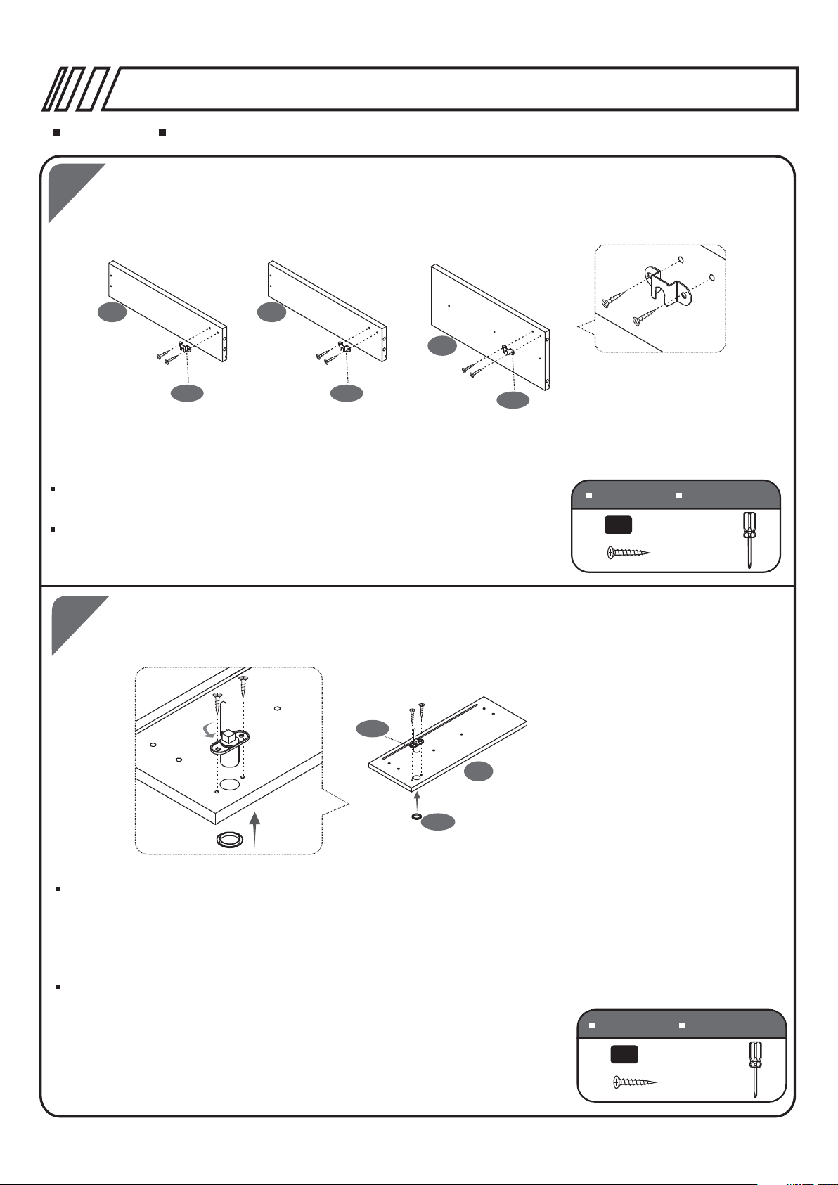
Use Screws (A) to fix the Metal Plates (37B) to the Small Drawer Left
Panels (21) and the File Drawer Left Panel (29).
Use tornillos (A) para fijar las partes (37B) a los Paneles Izquierdos de
las gavetas pequeñas (21) y el Panel Izquierdo de la Gaveta de Archivo (29).
37B
SCREWS
3X15 MM
A
TORN ILLOS
6PCS
2
37D
23
37G
Press the Metal Ring (37G) into the hole of the Top Drawer Front Panel (23)
from the face of the panel. Use Screws (A) to assemble the Lock (37D) to the
Top Drawer Front Panel (23).
Make sure the rod on the lock is facing down, and the key must turn
counter-clockwise.
Presione el Aro de metal (37G) sobre el hueco del Panel Superior de la
Gaveta Superior (23) por la parte delantera. Use tornillos (A) para ensamblar
el Cerrojo (37D) al Panel Frontal de la Gaveta Superior.
Aseg rese que el tubo del cerrojo quede en posición hacia abajo, y que la
ú
llave gire contra las manecillas del reloj.
SCREWS
3X15 MM
A
TORN ILLOS
2PCS
Page 11

3
RTA-4805L
21
23
25
22
22
21
25
24
22
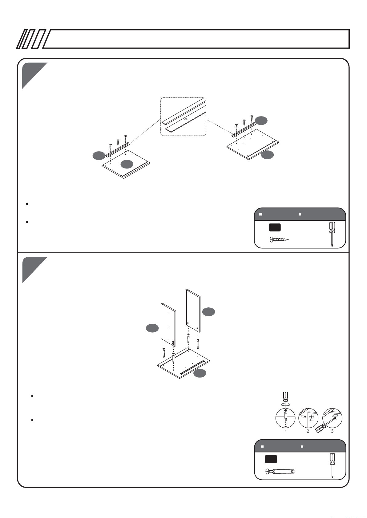
Screw Bolt (B) to the back of the Top Drawer
22
Front Panel (23) and the Middle Drawer Front
Panel (24). Place the Small Drawer Left &
Right Panels (21&22) over the Bolts (B) and
secure the Panels (21&22) by turning their
cam locks.
Slide down the Small Drawer Bottom Panels (25)
between the Left, Right, and Front Panels (21,
22, 23), making sure it fits into the grooves.
Atornille los pernos (B) a la parte posterior del
Panel Frontal de la Gaveta Superior (24).
Coloque los Paneles Derecho e Izquierdo (21 &
22) sobre los pernos (B), y asegure los paneles
(21 & 22) haciendo girar los cerrajes.
Deslice los Paneles Inferiores de las Gavetas
Pequeñas (25) entre los Paneles Izquierdo,
derecho y Frontal (21, 22 & 23), asegurándose
que quede entre los canales.
P.11
4
21
21
26
21
22
21
26
22
SCREWS
6X40 MM
B
TORN ILLOS
8PCS
Use Screws (H) to fix Small Drawer Back Panel (26) between Small Drawer
Left & Right Panels (21&22).
Use tornillos (H) para ensamblar el Panel Posterior de las Gavetas
Pequeñas (26) entre los paneles (21 & 22).
SCREWS
4X35 MM
H
TORN ILLOS
8PCS
Page 12

5
Izquierdo
Left
27
Izquierdo
Left
27
RTA-4805L
Derecho
Right
27
21
Derecho
Right
27
21
P.12
Derecho
Right
27
27
Left
Izquierdo
SEPARATE THE SLIDERS (27) BY
THEIR SHAPE: THE “L” SHAPE ONES
WILL BE USED IN STEP #5, AND THE
FLAT ONES IN STEP #17.
SEPARE LOS DESLIZADORES (27) DE
ACUERDO A SU FORMA: LOS QUE
TIENEN FORMA “L” SE USARÁN EN EL
PASO #5, Y LOS PLANOS EN EL PASO #17.
Align and match the selected holes of the moving part of the Small Drawer Sliders (27) with the pre-drilled
holes of the Small Drawer Left & Right Panels (21&22) as illustrated and then use Screws (A) to fix them.
Alinee los hoyos de la parte movible de los Deslizadores de las Gavetas Pequeñas (27) con los hoyos
pre-perforados en los paneles Izquierdo y Derecho (21 & 22) como se muestra, y luego asegúrelos con
los tornillos (A).
SCREWS
A
TORN ILLOS
3X15 MM
8PCS
6
24
33
23
33
Use Screws (I) to fix the Handles (33) to the Top Drawer Front Panel (23) and
Middle Drawer Front Panel (24).
Use tornillos (I) para ensamblar las manijas (33) al Panel Frontal de la Gaveta
Superior (23) y el Panel Frontal de la gaveta del medio (24).
SCREWS
4X20 MM
I
TORN ILLOS
4PCS
Page 13
7
RTA-4805L
P.13
35
35
31
Use Screws (A) to fix the Folder Hangers (35) to the File Drawer Front & Back
Panels (28&31).
Use tornillos (A) para ensamblar los Colgadores de la Gaveta de Archivo (35)
a los paneles (28 & 31).
8
30
29
28
SCREWS
3X15 MM
A
TORN ILLOS
6PCS
28
Screw Bolts (B) to the back of the File Drawer Front Panel (28). Place the
File Drawer Left & Right Panels (29&30) over the Bolts (B) and secure the
Panels (29&30) by turning their cam locks.
Atornille los pernos (B) a la parte posterior del Panel Frontal de la Gaveta de
Archivo (28). Coloque los Paneles Derecho e Izquierdo (29 & 30) sobre los
pernos (B), y asegure los paneles (29 & 30) haciendo girar los cerrajes.
SCREWS
6X40 MM
B
TORN ILLOS
4PCS
Page 14

9
10
RTA-4805L
36
29
31
30
P.14
Slide down the File Drawer Bottom Panel (36) between the Left, Right, and
Front Panels (28, 29 & 30), making sure it fits into the grooves.
Deslice los Paneles Inferiores de la Gaveta de Archivo (36) entre los
Paneles Izquierdo, derecho y Frontal (28, 29 & 30), asegurándose que
quede entre los canales.
Use Screws (H) to fix the File Drawer Back Panel (31) to the File Drawer Left
& Right Panels (29&30).
11
29
31
32
Use tornillos (H) para ensamblar el Panel Posterior de la Gaveta de
Archivo (31) a los paneles Izquierdo y Derecho (29 & 30).
30
SCREWS
4X35 MM
H
TORN ILLOS
4PCS
Insert the Hanging Files Tubes (32) and screw into File Drawer Front Panel (28).
Attention: Do not over tighten them, as doing so will cause
damaged to the panel.
28
Inserte los Tubos de Sostén para carpetas (32) atornillándolos al Panel
Frontal de la Gaveta de Archivo (32).
ATENCIÓN: No los apriete demasiado, porque pueden dañar
el panel.
Page 15

RTA-4805L
P.15
12
34
2
Palanca de cerradura
Corredara externa
34A 34B
Open the slider (34) and hold it as shown. Press the locking lever up hard with the tip of your thumb to
separate sliders into the outer rail (34a) and the inner rail (34b). (34b) will be used on step# 13, and (34a)
on step# 17.
Abra el deslizador (34) y sosténgalo como se muestra. Presione fuerte la palanca de cierre hacia arriba
con la punta del dedo para separar los deslizadores en partes (34a) y (34b). (34b) se usará en el paso #13,
y (34a) en el paso #17.
Corredara interna
13
14
29
34B
28
Use Screws (A) to fix the Inner Rail (34B) to the File Drawer
Left & Right Panels (29&30).
Use tornillos (A) para ensamblar los deslizadores (34B) a los
Paneles Izquierdo y Derecho de la Gaveta de Archivo (29 & 30).
34B
30
SCREWS
3X15 MM
A
TORN ILLOS
6PCS
Use Screws (I) to fix the Handle (33) to the File Drawer Front Panel (28).
33
Use tornillos (I) para ensamblar la manija (33) al Panel Frontal de la
Gaveta de Archivo (28).
SCREWS
4X20 MM
I
TORN ILLOS
2PCS
Page 16

15
RTA-4805L
37E
37F
37F
P.16
Tighten the metal plates
on the marked position
of the metal bar
Apriete las piezas entre la posición
marcada en la barra
16
37A
37A
37C
First slide into the Metal Bar (37E) the 5 Metal Plates in the order
shown in the drawing (37A, 37C, 37C, 37A, 37C). Then, tighten
the Metal Plates (37C) on the marked position of the Metal
Bar (37E) with Screws (37F).
Primero deslice en la Barra de Metal (37E) las 5 piezas metálicas
en el orden mostrado (37A, 37C, 37C, 37A, 37C). Después, apriete
las piezas (37C) entre la posición marcada en la barra (37E),
con los tornillos (37F).
37F
1
37A
Use Screws (A) with the Metal Plates (37A) to assemble the Metal
Bar (23E) to the Left Panel (1).
Use tornillos (A) con las piezas (37A) para ensamblar la barra (23E)
al panel (1).
SCREWS
3X15 MM
A
TORN ILLOS
8PCS
Page 17

17
RTA-4805L
27
Izquierdo
Left
27
X2
Derecho
Right
27
P.17
34A
Frente
X2
1
Use Screws (A) to assemble the Small Drawer Sliders (27) and the Outer
Rails (34A) to the Left & Right Panels (1&2). On (27), use the second hole
from the front, and third hole from the end. On (34A), use the second and
fifth hole from the end. Do not screw (34A) at the front yet.
Use tornillos (A) para ensamblar los Deslizadores de la Gaveta Pequeña (27)
y los rieles (34A) a los paneles Izquierdo y Derecho (1 & 2).En (27), use el
Segundo hueco del frente, y el tercero del final. En (34A), use el Segundo y
quinto hueco del final. No atornille (34A) al frente todavía.
34A
34A
2
18
34A
Frente
SCREWS
3X15 MM
A
TORN ILLOS
12PCS
1
34A
Close the rails (34A) and slide the part with the bearings towards the back.
The front hole will be visible on (34A), and secure them with screws (A).
Cierre los rieles (34A) y deslice la balinera hacia atrás. El hueco del frente
quedará visible en (34A), y asegúrelos con tornillos (A).
2
SCREWS
3X15 MM
A
TORN ILLOS
2PCS
Page 18

RTA-4805L
19
3
2
1
First screw the Bolts (B) on the inside face of the Left & Right Panels (1&2).
Place the Back Panel (3) over the Bolts and tighten all cam locks on the inside
face of Back Panel (3).
P.18
Primero atornille los pernos (B) en la parte interior the los Paneles Izquierdo y
Derecho (1 & 2). Coloque el Panel Posterior (3) sobre los pernos y gire todos
los cerrajes de la parte interior del Panel Posterior (3).
20
4
8
X4
6
9
SCREWS
6X40 MM
B
X4
6
X4
5
TORN ILLOS
4PCS
Fix the Studs (6) to the Left & Right Frames (8&9). Use Screws (C) to assemble
the Legs Bottom Support Tube (5) to the Bottom Panel (4). Then fix the Studs (6)
to the tubes (5).
Inserte los Topes (6) a las Estructuras Izquierda y Derecha (8 & 9). Use tornillos (C)
para ensamblar los Tubos de Soporte Inferior (5) al Panel Inferior (4). Luego ensamble
los Topes (6) a los tubos (5).
SCREWS
C
TORN ILLOS
6X25 MM
4PCS
Page 19

21
RTA-4805L
7
1
P.19
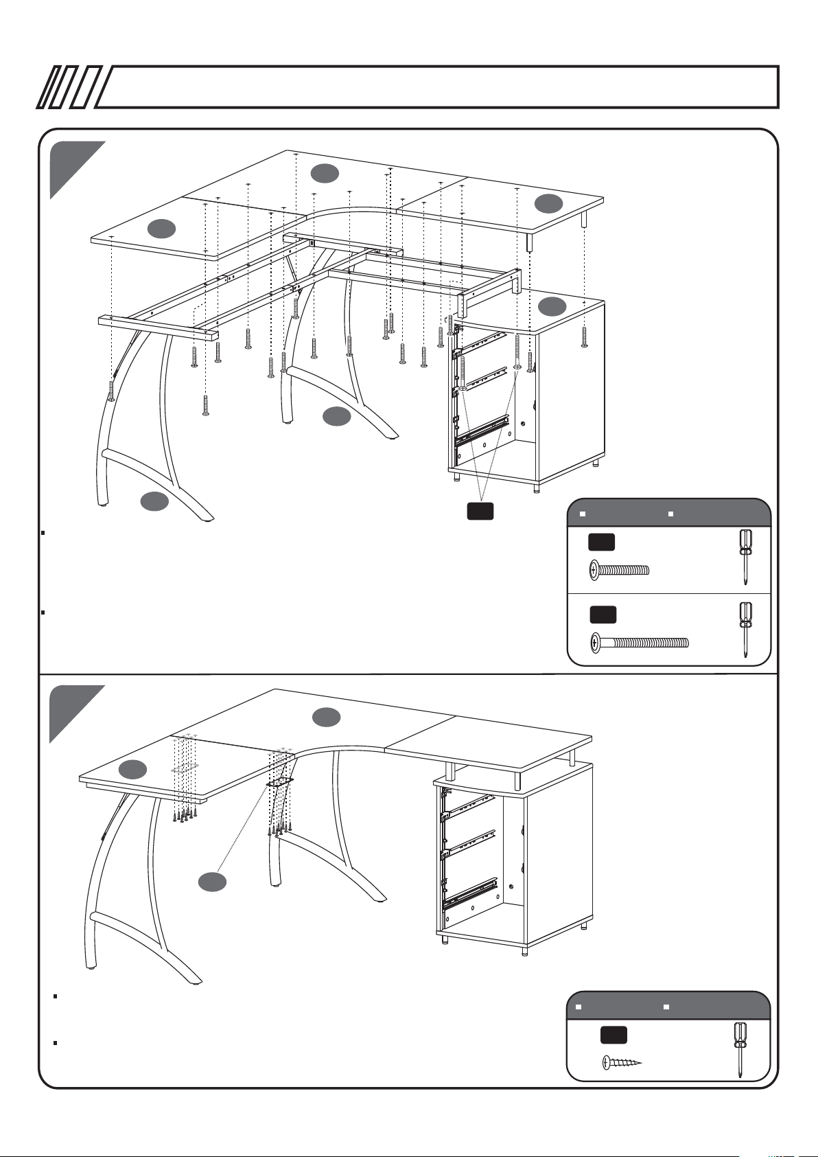
Screw the Bolts (B) in the corresponding holes of the back face of
the Bottom & Top Panels (4&7). Then place the Left & Right
Panels (1&2) over the bolts of the Bottom Panel (4). Then insert the
bolts of the Top Panel (7) into the holes of the Left & Right
Panels (1&2). Finally tighten the cam locks in the inside faces of the
Left & Right Panels (1&2).
Atornille los pernos (B) en los hoyos correspondientes en la parte
2
posterior de los Paneles Superior e Inferior (4 & 7) . Luego coloque
los Paneles Izquierdo y Derecho (1 & 2) sobre los pernos del Panel
Inferior (4). Luego inserte los pernos del Panel Superior (7) en los
hoyos de los Paneles Izquierdo y Derecho (1 & 2). Por ultimo, gire
los cerrajes en la parte interior de los
Paneles Izquierdo y Derecho (1 & 2).
22
4
SCREWS
6X40 MM
B
TORN ILLOS
12PCS
15
15
16
Use Screws (C) to fix the Top Support Tubes (15) to the Small Table Panel (16).
Use tornillos (C) para unir los los Tubos de Soporte Superior (15) al Panel de mesa pequeño (16).
SCREWS
6X25 MM
C
TORN ILLOS
2PCS
Page 20

RTA-4805L
P.20
23
23
10
10
11
11
12
12
Insert the Right Connect Tubes (12) into the Left Front
Connect Tube (10) and Left Back Connect Tube (11).
Use Screws (D&J) to tighten them.
Inserte los Tubos de Conección Derecho (12) en el
Tubo frontal de Conección Izquierdo (10) y el Tubo
Posterior de Conección Derecho (11). Use tornillos
y tuercas (D & J) para asegurarlos.
12
TORN ILLOS
4PCS
4PCS
12
SCREWS
6X35 MM
D
M6
J
24
39
40
Use Screws (L) to fix the Back Structures (39) to the Long Back Panel (40).
Use tornillos (L) para ensamblar la Estructura posterior (39) al Panel Posterior Largo (40).
SCREWS
6X20 MM
L
4PCS
TORN ILLOS
Page 21

RTA-4805L
**There are 2 options to assemble your desk, please choose it
according to your preference, and follow the next steps A or B.
**Hay 2 opciones para ensamblar su escritorio, por favor escoja
una de acuerdo a su preferencia, y continue con los siguientes
pasos A o B.
P.21
A -A71
A
B
B1-B7
Page 22

RTA-4805L
A1
8
9
10
11
12
Use Screws (E) to fix the Left Front Connect Tube, Left Back Connect Tube
and Right Connect Tube (10, 11&12) to the Left & Right Frames (8&9).
Please pay attention to the position of the tubes as shown.
Use tornillos (E) para ensamblar el Tubo Conector Frontal de la Izquierda, el
Tubo posterior de conección derecho y el Tubo Conector derecho (10, 11 & 12)
a las estructuras Izquierda y Derecha (8 & 9). Por favor fíjese bien en las
posiciones de los tubos tal como se muestra.
SCREWS
6X12 MM
E
16PCS
P.22
TORN ILLOS
A2
8
J
E
14
D
11
12
E
D
13
Assemble the Right Support Structure (13) to the Right Frame (9) and Right
Connect Tube (12) using Screws (D, E, J). Assemble the Left Support
Structure (14) to the Left Frame (8) and Left Back Connect Tube (11) using
Screws (D, E, J). Please pay attention to the position of the screws.
Ensamble la Estructura de Soporte Derecha (13) a la Estructura Derecha (9)
y el Tubo Conector Derecho (12) usando tornillos (D, E, J). Ensamble la
Estructura de soporte izquierda (14) a la Estructura Izquierda (8) y el Tubo
posterior de conexión derecho (11) usando tornillos (D, E, J). Por favor fíjese
bien en las posiciones de los tornillos tal como se muestra.
J
9
SCREWS
6X35 MM
D
6X12 MM
E
2PCS
M6
J
TORN ILLOS
2PCS
2PCS
Page 23

A3
RTA-4805L
P.23
17
17
10
18
SCREWS
6X40 MM
G
TORN ILLOS
4PCS
Use Screws (G) to assemble the Long Tubes (17) between the Left Front Connect Tube (10) and the
Support Frame (18).
Use tornillos (G) para ensamblar los Tubos Largos (17) entre el Tubo frontal de conexión izquierdo (10)
y la Estructura de soporte superior (18).
A4
19
16
SCREWS
6X35 MM
D
6X115 MM
F
TORN ILLOS
18PCS
2PCS
20
7
8
9
F
Assemble the Small Table Panel (16), the Corner Table Panel (19) and the
Big Table Panel (20) using Screws (D&F).
DO NOT TIGHTEN ANY SCREWS UNTILL ALL ARE IN PLACE.
Please pay attention of the position of the screws.
Ensamble el Panel de mesa pequeño (16), Panel de Mesa Esquinero (19),
y el Panel de Mesa Grande (20) usando tornillos (D & F).
NO APRIETE NINGUN TORNILLO HASTA QUE TODOS ESTÉN COLOCADOS.
Por favor fíjese bien en las posiciones de los tornillos tal como se muestra.
Page 24

RTA-4805L
P.24
A5
Assemble the Connect Metal Plates (38) on the bottom and between the
Corner Table Panel (19) and the Big Table Panel (20) using Screws (K).
Ensamble los Platos Metálico de Conexión (38) por debajo y entre medio
del Panel de Mesa Esquinero (19) y el Panel de Mesa Grande (20) usando
tornillos (K).
19
38
X2
20
SCREWS
4X14 MM
K
TORN ILLOS
16PCS
A6
1st
Inner sil ver ball
bearing s li de
HUMP
23
24
28
Make sure inner silver ball
bearing slide is at the front
of the slide mount and in
lock position(over the hump),
as shown.
Asegúrese que las bal ineras
estén hacia el frente como se
muestra.
2nd
Alig n bo th sides of s li de runner s
to sli de m ounts' op en ings,th en
slid e al l the way in. Ap ply small
forc e to i nsert com pl etely if ne ed ed
Alinee los deslizad ores en ambos
lados y deslice lenta y firmemente .
Aplique un poco de fuerza si fuera
necesario.
Carefully slide drawers onto rails and push firmly and evenly until they are completely closed.
Deslice firme pero cuidadosamente las gavetas hasta que queden completamente cerradas.
Page 25

A7
RTA-4805L
P.25
19
20
40
Use Screws (L) to assemble the Back Structures (39) to the Big Table
Panel (20) and the Corner Table Panel (19).
Use tornillos (L) para ensamblar las Estructuras Posteriores (39) al Panel
de Mesa Grande (20) y al Panel de Mesa Esquinero (19).
39
SCREWS
L
TORN ILLOS
6X20 MM
4PCS
B1
9
8
10
11
12
Use Screws (E) to fix the Left Front Connect Tube, Left Back Connect Tube and Right Connect
Tube (10, 11&12) to the Left & Right Frames (8&9). Please pay attention to the position of the
tubes as shown.
Use tornillos (E) para ensamblar el Tubo Conector Frontal de la Izquierda, el
Tubo posterior de conección derecho y el Tubo Conector derecho (10, 11 & 12)
a las estructuras Izquierda y Derecha (8 & 9). Por favor fíjese bien en las
posiciones de los tubos tal como se muestra.
SCREWS
6X12 MM
E
16PCS
TORN ILLOS
Page 26

B2
RTA-4805L
8
E
P.26
9
J
E
13
11
D
12
D
J
Assemble the Right Support Structure (13) to the Right Frame (9) and Left
Back Connect Tube (11) using Screws (D, E, J). Assemble the Left Support
Structure (14) to the Left Frame (8) and Right Connect Tube (12) with using
Screws (D, E, J). Please pay attention to the position of the screws.
Ensamble la Estructura de Soporte Derecha (13) a la Estructura Derecha (9)
y el Tubo Posterior de Conexión Derecho (11) usando tornillos (D, E, J).
Ensamble la Estructura de soporte izquierda (14) a la Estructura Izquierda (8)
y el Tubo de conexión derecho (12) usando tornillos (D, E, J). Por favor fíjese
bien en las posiciones de los tornillos tal como se muestra.
B3
14
10
17
17
SCREWS
6X35 MM
D
6X12 MM
E
2PCS
M6
J
TORN ILLOS
2PCS
2PCS
18
Use Screws (G) to assemble the Long Tubes (17) between the Left Front
Connect Tube (10) and the Support Frame (18).
Use tornillos (G) para ensamblar los Tubos Largos (17) entre el Tubo frontal
de conexión izquierdo (10) y la Estructura de soporte superior (18).
SCREWS
6X40 MM
G
TORN ILLOS
4PCS
Page 27
RTA-4805L
P.27
B4
19
16
20
7
9
8
Assemble the Small Table Panel (16), the Corner Table Panel (19) and the
Big Table Panel (20) using Screws (D&F).
DO NOT TIGHTEN ANY SCREWS UNTILL ALL ARE IN PLACE.
Please pay attention of the position of the screws.
Ensamble el Panel de mesa pequeño (16), Panel de Mesa Esquinero (19),
y el Panel de Mesa Grande (20) usando tornillos (D & F).
NO APRIETE NINGUN TORNILLO HASTA QUE TODOS ESTÉN COLOCADOS.
Por favor fíjese bien en las posiciones de los tornillos tal como se muestra.
F
SCREWS
6X35 MM
D
6X115 MM
F
TORN ILLOS
18PCS
2PCS
B5
19
20
X2
38
Assemble the Connect Metal Plates (38) on the bottom and between the
Corner Table Panel (19) and the Big Table Panel (20) using Screws (K).
Ensamble los Platos Metálico de Conexión (38) por debajo y entre medio
del Panel de Mesa Esquinero (19) y el Panel de Mesa Grande (20) usando
tornillos (K).
SCREWS
4X14 MM
K
TORN ILLOS
16PCS
Page 28

B6
RTA-4805L
P.28
23
24
28
1st
Inner sil ver ball
bearing s li de
HUMP
Carefully slide drawers onto rails and push firmly and evenly until they are completely closed.
Deslice firme pero cuidadosamente las gavetas hasta que queden completamente cerradas.
Make sure inner silver ball
bearing slide is at the front
of the slide mount and in
lock position(over the hump),
as shown.
Asegúrese que las bal ineras
estén hacia el frente como se
muestra.
2nd
Alig n bo th sides of s li de runner s
to sli de m ounts' op en ings,th en
slid e al l the way in. Ap ply small
forc e to i nsert com pl etely if ne ed ed
Alinee los deslizad ores en ambos
lados y deslice lenta y firmemente .
Aplique un poco de fuerza si fuera
necesario.
B7
39
20
40
19
Use Screws (L) to assemble the Back Structures (39) to the Big Table
Panel (20) and the Corner Table Panel (19).
Use tornillos (L) para ensamblar las Estructuras Posteriores (39) al Panel
de Mesa Grande (20) y al Panel de Mesa Esquinero (19).
SCREWS
6X20 MM
L
4PCS
TORN ILLOS
Page 29

CARE AND MAINTENANCE
English
- DO NOT EXPOSE THE SURFACES TO DIRECT SUNLIGHT, OR
EXTREME ENVIRONMENTAL CONDITIONS. EXPOSURE WILL
DAMAGE THE PRODUCT, WHICH IS NOT COVERED BY THE
WARRANTY.
- DO NOT USE SOLVENTS OVER SURFACES OR STRUCTURAL
TUBES. SURFACES MUST BE CLEANED WITH A SOLUTION OF
A SMOOTH SOAP AND WATER, THEN CLEARED WITH A DRY
TOWEL.
- PRODUCTS THAT ARE HEAVY SHOULD BE LIFTED OR MOVED
BY AT LEAST 2 PERSONS, AND ALL OBJECTS SHOULD BE
REMOVED FROM THE PRODUCT.
Spanish
- NO EXPONGA LAS SUPERFICIES A LA LUZ SOLAR DIRECTA,
O A CONDICIONES AMBIENTALES EXTREMAS. ESTE TIPO DE
DAÑOS NO SON CUBIERTOS POR LA GARANTÍA DEL PRODUCTO.
- NO USE SOLVENTES SOBRE LAS SUPERFICIES O TUBOS
ESTRUCTURALES. LAS SUPERFICIES DEBEN SER LIMPIADOS
CON UN JABÓN SUAVE Y AGUA, Y SECADOS IMMEDIATAMENTE
CON UNA TOALLA LIMPIA Y SECA.
- PRODUCTOS QUE SON PESADOS DEBEN LEVANTARSE O
MOVERSE POR AL MENOS 2 PERSONAS, Y TODOS LOS
OBJETOS DEBEN SER REMOVIDOS DEL PRODUCTO.
Page 30

PRODUCT WARRANTY
TECHNI MOBILI DESK WARRANTY
LIMITED 5-YEAR WARRANTY
RTA Products, LLC warrants to the Original Purchaser who acquired a new product from RTA Products or its
authorized resellers that this product will be free from defects in its workmanship and materials, under normal
use and service conditions, as described herein. "Defects" as used in this warranty, is dened as any
imperfections that impair the use of the furniture or product. RTA products will repair or replace, at is option,
without charge to the original purchaser ‘other than freight from purchaser to RTA Products, only the defective
products or parts for a period of FIVE (5) Years.
Replacement parts can only be supplied if parts are available. Items out of production may be unavailable.
This warranty will be effective for the applicable time period beginning the date of purchase on your original
sales receipt. RTA product’s obligation under this warranty is limited to repairing or replacing products or parts
as provided herein. This product has been designed for and is intended for ofce and home-ofce use only.
This warranty is Original Purchaser’s sole remedy for product defects, and this warranty does not extend to
any product, or damage to any product, caused by or attributed to abuse or misuse, products used for
commercial or rental purposes, use modications of, or attachments to the product, and products or parts not
used, maintained, or extended hereunder is in lieu of any and all other warranties, express or implied, including
without limitations any implied warranty or merchantability or of tness for a particular purpose. Please note, all
desks made with PVC Laminate surface should not be exposed to direct sunlight, as it may damage the
material. Damage of this nature is not covered under this warranty.
RTA Products will not be responsible for indirect, special, incidental or consequential damages. This warranty
is limited to merchandise purchased in the Continental United States. Some States do not allow the exclusion
or limitation of incidental or consequential damages, so the above limitations or exclusions may not apply to
you. This warranty gives you specic legal rights. You may also have other rights that may vary from state to
state.
RTA Products will advise you of the procedure to follow in making warranty claims. The following are the
procedures for warranty claims:
a. Call us Monday – Friday, from 9am-5pm (Eastern Time) at (866) 782-8262 to explain the defect and give
your name, address and phone number. Please have ready the model number of our product, date and place
of purchase. You can also write to us by e-mail to warranty@rtaproducts.com and include the same
information.
b. If we determine that replacement will remedy the situation, and in order to determine the extent or the cause
of the defect, purchaser will need to send the part in question at purchaser’s expense. Once we receive the
part, we will examine it and determine whether the claim is valid (or not), and then proceed to send the
replacement. We will ship the replacement at our expense.
 Loading...