

Page 1
ASSEMBLY INSTRUCTIONS
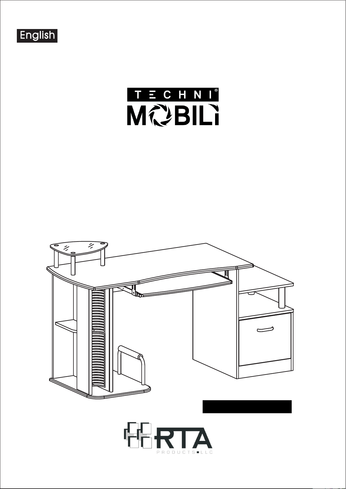
MODEL RTA - 2202
Thanks for purchasing one of our products.
Please read carefully the assembly instructions before the installation.
Please save this manual for future reference.
MODEL RTA- 2 2 0 2
Page 2
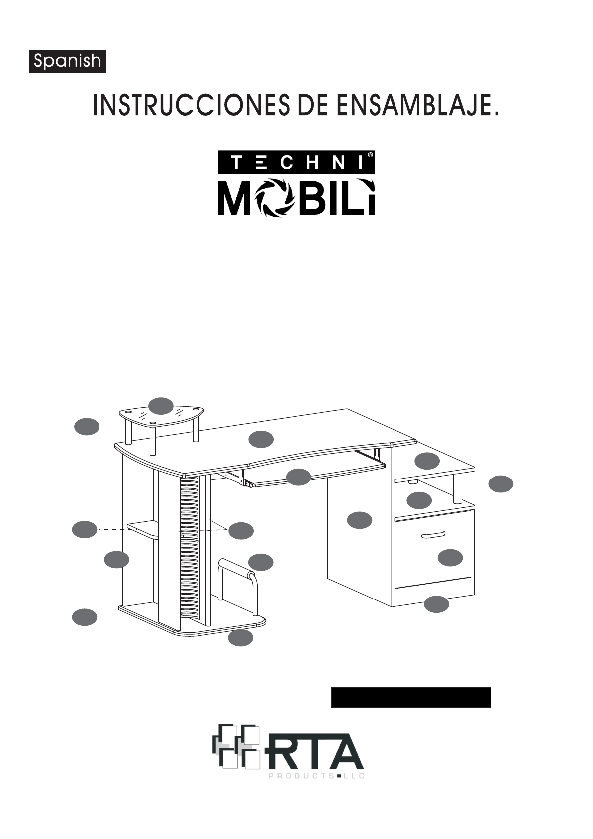
MODELO RTA - 2202
Gracias por comprar uno de nuestros productos.
Por favor lea cuidadosamente las instrucciones de ensamblaje antes de
instalar la unidad.
Por favor guarde este manual para referencias futuras.
29
28
27
15
24
12
18
22
30
21
16
19
14
13
1
8
MODE LO RTA-2202
Page 3
RTA-2202
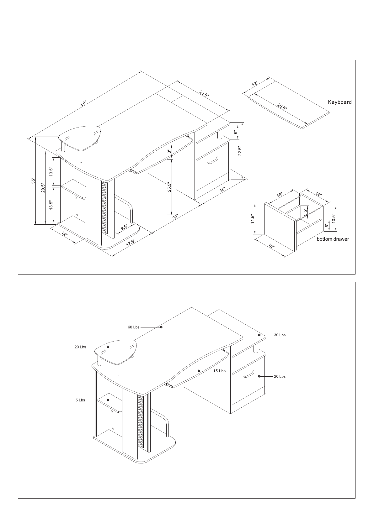
DIMENSIONS
Product Siz e: 60"W x 23 1/2"D x 35" H
MAXIMUM WEIGHT CAPACITIES
DO NOT exceed t his limit
Please use ca re and good judgement
when placin g objects on wood surface
Page 4
RTA-2202
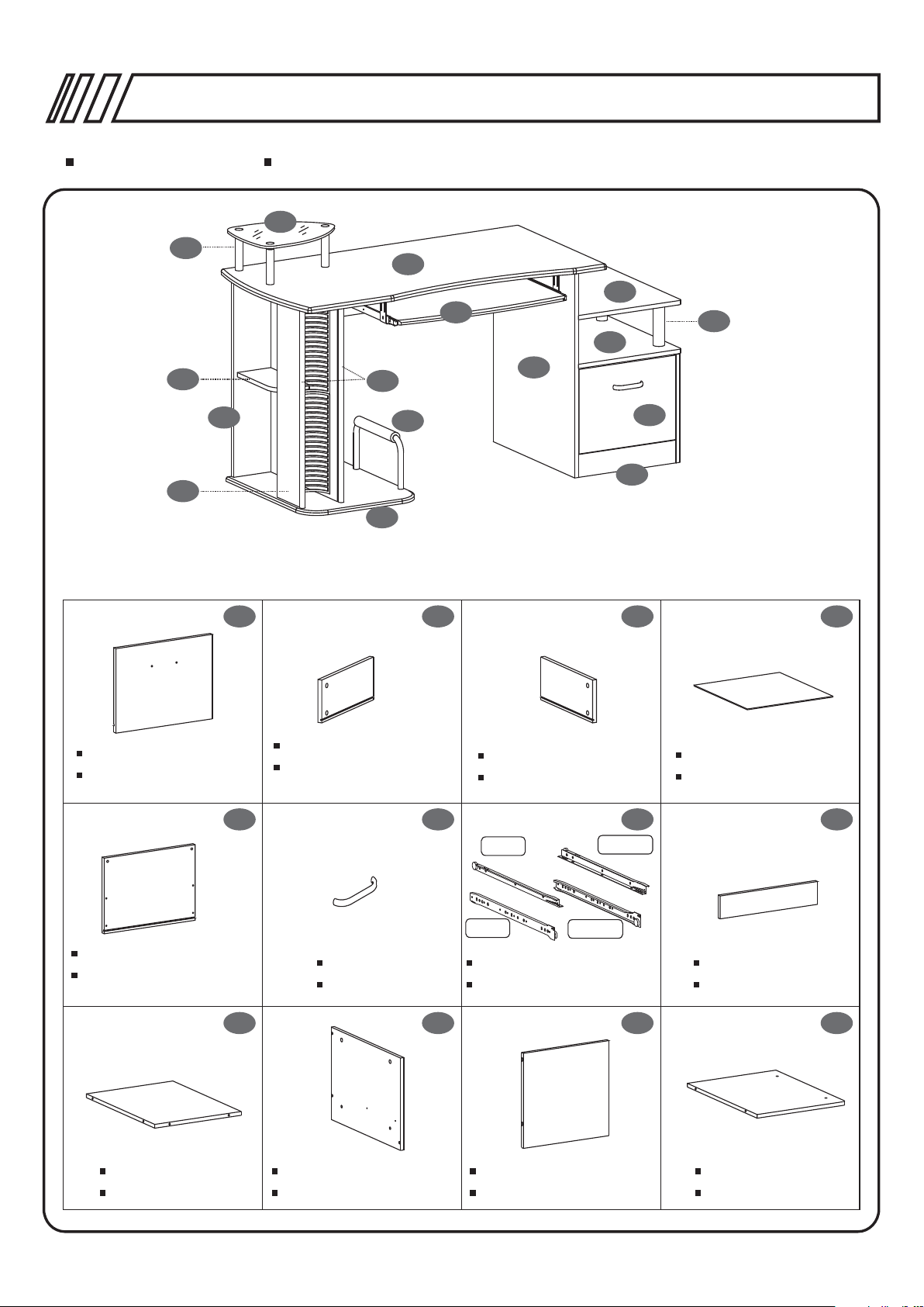
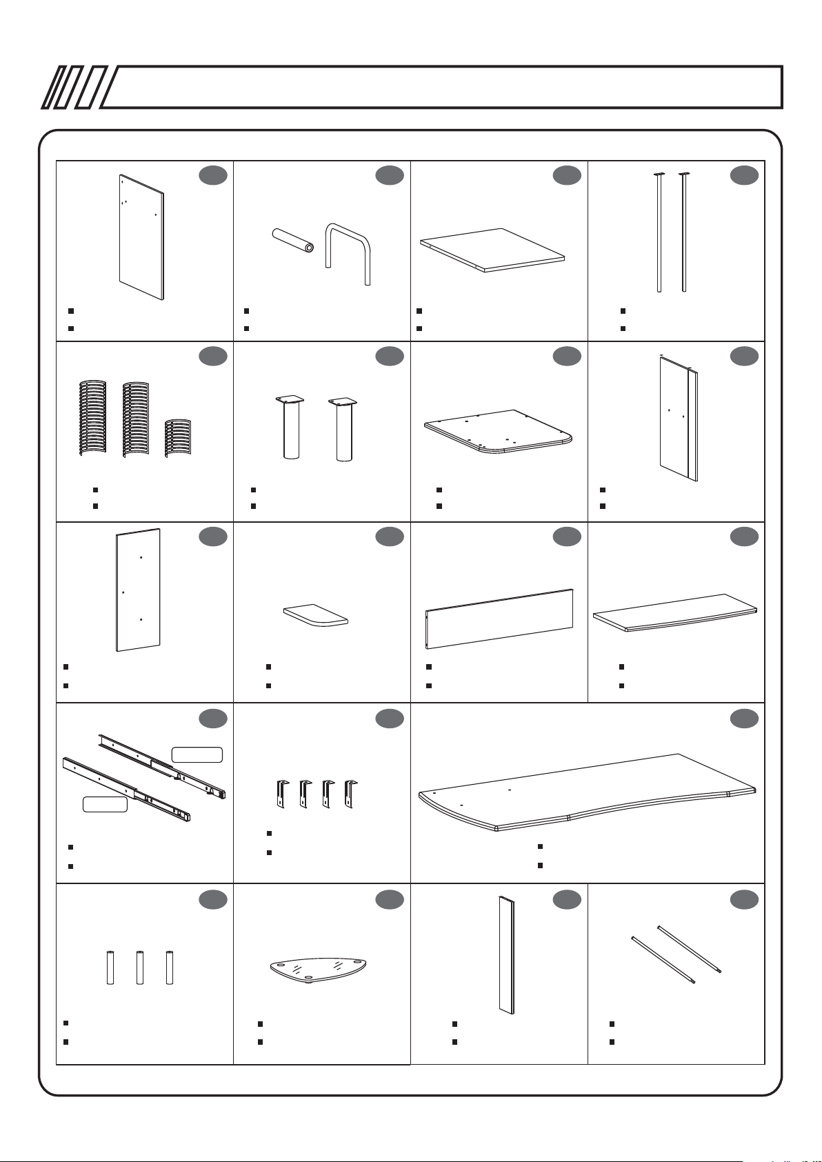
PARTS LIST LISTA DE PIEZAS
29
28
27
24
22
16
P.4
15
18
12
13
21
30
1 2 3 4
Drawer Front Pa nel
Panel frontal de gaveta
5 6 7 8
14
19
Drawer Left Panel
Panel lateral izquierdo
de gaveta
8
Drawer Right Pa nel
Panel lateral derecho
Left
Right
1
Drawer Bottom Panel
Fondo de Gaveta
Drawer Back Panel
Panel posterior de
gaveta
Bottom Panel
Panel Bajo
Left
Right
x2 sets
Handle
Manija Deslizadores de gaveta
Drawer Sliders
Front Panel
Panel frontal
9 10 11 12
Right Vertical Panel Right Back Panel
Panel vertical derecho
Panel de fondo derecho
Drawer Top
Techo de Gave ta
Page 5
RTA-2202
13 14 15 16
P.5
Inside Vertica l Panel Protector Tube
Panel vertical interno
Tubo prot ector de CP U
17 18 19 20
x1 set
CD Holders
Porta CD
Big Support Tubes
Soportes Grandes Panel para CPU
21 22 23 24
Left Back Panel
Panel posterior izqu ierdo
Auxiliary Panel
Panel auxiliar
x1 set
x2 ea.
x2 ea.
Right Horizon tal Panel
Panel horizontal derecho Tubos Verticales
CPU Panel
Center Back Panel
Panel central de fondo
Vertical Tubes
Left Vertical Panel
Panel Vert ical izqu ierdo
Keyboard Panel
Panel de teclado
25 26 27
RI GHT
LE FT
x1 set
Keyboard Slid er
Deslizadores de tecl ado
28 30 3129
x3 ea.
Small Support Tubes
Tubos por ta monito r
x4 ea.
Slider Bases
Escuadras para
Deslizadores
Monitor Panel
Panel p/monitor
Main Panel
Panel principal
CDs Wall
Pared de Cds
x2 ea.
Tubes for F iles
Tubos por ta Carpet a
Page 6
RTA-2202
P.6
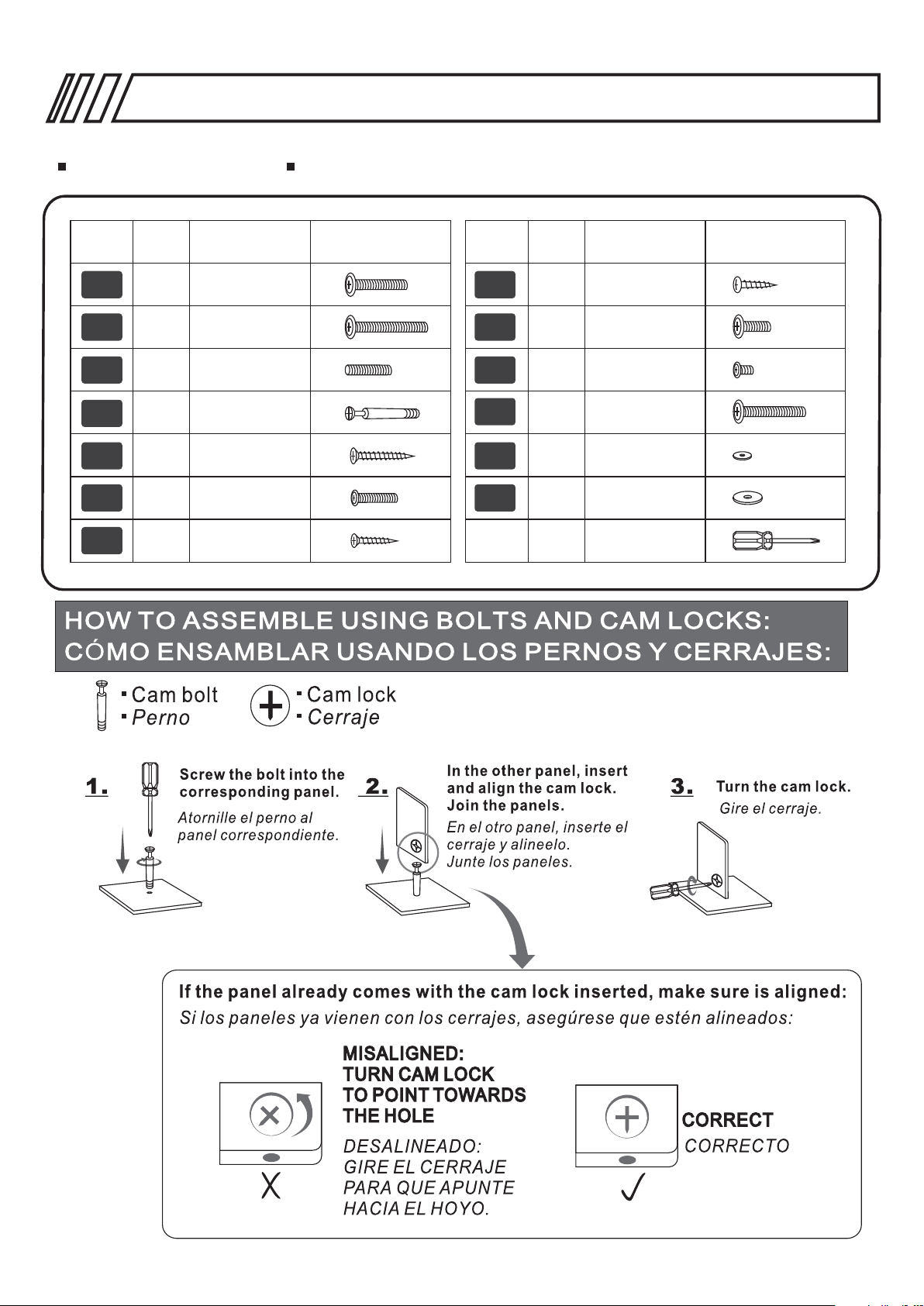
SCREWS LIST
PART
A
B
C
D
E
F
G
QTY.
7
3
3
47
4
2
8
ITEM PART
6X30 MM
6X50 MM
6X20 MM
6X40 MM
4X30 MM
4X20 MM
3X15 MM
TORNILLOS
H
J
K
L
M
QTY.
12
I
4
2
3
2
1
ITEM
4X14 MM
6X12 MM
4X4 MM4
6X40 MM
Page 7
30mm
RTA-2202
Page 8

RTA-2202
Page 9

RTA-2202
PASOSSTEPS
P.9
1
2
Assemble with the tool the Cam Bolts (D) to the back face of the
Drawer Front Panel (1). Then place over the bolts the Drawer Left
3
2
1
panel (2) and the Drawer Right Panel (3), and turn the cam locks.
Ensamble con la herramienta los Pern os ( D) e n el reverso del Panel
Frontal de Gaveta (1). Luego coloque sob re l os p ernos el Panel Lateral
Izquierdo de gaveta (2) y el panel la teral Derec ho d e ga veta (3), y gire
los cerrajes.
SCREWS
6X40 MM
D
TO RNILLO S
4PCS
4
Slide the Drawer Bottom Panel (4) between the groves of (2)
and (3), making sure it enters into the grove of (1).
3
Deslice el Panel de Fondo de gave ta ( 4) p or l as r anuras de (2) y (3),
y asegúrese que entre en la ranur a de (1) .
3
2
5
Use Screws (E) to Fix the Drawer Back panel (5) to the Drawer's
Left and Right Panels (2 and 3)
Coloque el panel poste rior de gav eta (5) y aju ste con tornillos (E).
3
2
SCREWS
E
TO RNILLO S
4X30 MM
4PCS
Page 10

RTA-2202
P.1 0
4
5
31
5
WARNING: Do not overtighten the tubes as they may perforate
and damage the front panel. Such damage is not cov ered by the
product's warranty.
ADVERTENCIA: No apriete los tubos demasiado porque pu eden
perforar y dañar el panel frontal . Este tipo d e daño no est á cubiert o
por la garantía del producto.
Insert the Tubes for F iles (31) .
Inserte los Tubos Porta Carpeta (31).
Right
7
Left
7
2
SCREWS
3X15 MM
G
TO RNILLO S
4PCS
Set aside the flat sliders (7), they are used until the next step. Turn drawe r up side-down and
assemble the “L” type sliders (7) to the side panels of the drawer (2) & (3), making the holes align
with the pre-drilled holes, and with the wheel s fa cing to the back, then fix them wit h sc rews (G).
Make sure the sliders are in contact with the side panels, and tha t there is n o pa rt o f th em “ up i n
the air”.
Separe los deslizadores plan os ( 7) p ara ser usados hasta el próximo paso. Vire la gaveta hacia abajo
y ensamble los deslizadores (7) tipo “L” a los paneles laterales (2) y (3), haciendo coincidir los aguj eros
con los pre-taladrados y con las ruedas en la parte tras era, luego fíjelos con los tornillos (G).
Page 11

6
RTA-2202
P.11
7
13
6
1
Using Screws (F) and from the inside of t he
Drawer install the handle (6).
Presente la manija (6) y f jela con tornillos (F)
desde el interior de la gaveta.
í
SCREWS
4X20 MM
F
TO RNILLO S
2PCS
Use screws (G) to assemble the flat Sliders (7)
to the Right Vertical Panel (10) and the Inside
Vertical Panel (13). The wheels will be facing
towards the front of the panels .
Use tornillos (G) para ensamblar los Des lizadores
planos (7) al Panel Vert ical (10) y al P anel Vertical
Interno (13). Las ruedas quedará n ha cia el f rente
10
de los paneles.
7
7
Left
Right
8
9
8
Use Bolts (D) to assemble the Bottom Panel (9) with the front panel (8).
Ensamble el panel bajo ( 9) con el pan el fronta l (8) utilizando pernos (D).
SCREWS
3X15 MM
G
SCREWS
6X40 MM
D
TO RNILLO S
4PCS
TO RNILLO S
2PCS
Page 12

9
RTA-2202
P.1 2
11
Use Bolts (D) to assemble the Right Back Panel (11) with
the Right Vertical Panel (10)
Con pernos ( D) ensamble e l panel de fo ndo derec ho (11) con
el panel vertical dere cho (10).
10
10
10
9
8
Use Bolts (D) to assemble parts 8-9-10-11 as shown in the drawing.
Utilice pernos (D) para ensambl ar las part es 8-9-10 y 11 com o indica
el gr fico.
á
SCREWS
6X40 MM
D
SCREWS
6X40 MM
D
TO RNILLO S
2PCS
TO RNILLO S
3PCS
11
12
11
10
Place Bolts (D) on the back face of the Drawer T p (1 2)
and assemble this panel with the previous structure,
so that the Bolts match the holes.
En el reverso del Techo de Gaveta (12) coloque pernos (D)
y ensamble con la estruc tura ante rior haci endo coincidir
los pernos con los aguje ros.
SCREWS
6X40 MM
D
o
TO RNILLO S
4PCS
Page 13

RTA-2202
P.1 3
12
13
13
15
18
18
12
9
Use Bolts (D) to Fix the Inside Vertical Panel (13).
Fije el panel vertical interno (1 3) utiliz ando pernos (D).
SCREWS
6X40 MM
D
TO RNILLO S
7PCS
8
Use Screws (H) to fix the Big Support tub es (18)
to the back face of the Right Horizontal Panel (15).
Con tornillos (H) fije los Soportes grande s (18) en el
reverso del panel Hori zontal de recho (15).
SCREWS
4X14 MM
H
TO RNILLO S
4PCS
14
X2
D
15
18
X2
X2
M
12
13
X2
K
First place and align washers (M) over the holes of the Drawe r Top
panel (12). Next, assemble the Bolts (D) to the Vertical Panel (13) and
assemble to it the Right Horizontal Panel (15). Finally, use s crews (K)
to assemble the Big Support Tubes (18) to th e Drawer Top (12) and
proceed to turn the cam locks on panel (15).
Primero coloque y alin ee arande las (M) sob re los orificios del Panel
Superior de gaveta (12). Despué s, ensamb le los pernos (D) al Panel
Vertical ( 13) y ensam ble el Pane l Derecho Horizontal (15). Finalme nte,
use tornillos (K) para ensambla r los Tubos de Sop orte Gran des (18) al
Panel Superior de Gave ta (12) y pro ceda a gira r los cerrajes en el
panel (15).
SCREWS
6X40 MM
K
6X40 MM
D
M
TO RNILLO S
2PCS
2PCS
2PCS
Page 14

RTA-2202
P.1 4
15
16
22
21
20
22
20
Use Screws (B) to fix the Auxiliary Panel (22) to the Left Vertical
Panel (20).
Use tornillos (B) para ensambla r el Panel Auxiliar (22) al Panel
Vertical Izquierd o (20).
SCREWS
6X50 MM
B
TO RNILLO S
2PCS
Use Screws (B&D) to assemble the Left Back Panel (21) to
the Left Vertical Panel (20) and Auxiliary P anel (22) .
Use tornillos (B&D) para ensamb lar el Panel Posterior
Izquierdo (21) al Pane l Vertical Izquierdo (20) y al Panel
Auxiliar (22).
17
14
19
14
SCREWS
6X50 MM
B
TO RNILLO S
1PC
6X40 MM
D
2PCS
Use Screws (A) to fix the Protector
Tube (14) t o the CPU Pan el (19).
Con tornillos (A) fije el Tubo Protector (14)
al Panel para CPU (19).
SCREWS
6X30 MM
A
TO RNILLO S
2PCS
Page 15

18
RTA-2202
P.1 5
Insert Bolts (D) in the CPU Panel (19) and then place the unit
of panels 20&21 over the Bolts.
19
21
19
30
16
20
En los agujeros dispue stos para e llo en el panel para CPU (19) coloque
pernos (D) y sobre ellos inserte la u nidad con formada por los paneles
20-21.
SCREWS
6X40 MM
D
TO RNILLO S
4PCS
Fr on t Side
16
16
Si de View
Make sure to assemble
19
Part 16 as illustrated.
Aseg rese de ensamblar
la parte 16 como se muestra
en la ilustraci n.úó
Insert Bolts (D) to the CPU Panel (19), then place the CDs Wall (30)
on the bolts and se cure the cam locks. Use Screws (A) to fix the
Vertical Tubes (16) to the CPU Panel (19).
Coloque los pernos (D) al Panel par a CPU (19), luego coloque la Pared
de CDs (30) sobre los pernos y gire los cerrajes . Use torni llos (A) pa ra
ensamblar los Tubos Verticales (1 6) al Panel p ara CPU (19).
SCREWS
6X30 MM
A
6X40 MM
D
TO RNILLO S
2PCS
2PCS
Page 16

20
RTA-2202
20
P.1 6
23
13
Use Bolts (D) to assemble the Center Back Panel (23) between the Left Vertical P anel (20) a nd
the Inside Vertical Panel (13).
Con pernos (D) ensambl e el Panel ce ntral de fo ndo (23) entre el panel vertical izqui erdo (20) y
el panel vertical interno (13). .
SCREWS
6X40 MM
D
TO RNILLO S
4PCS
21
X4
26
27
Use Screws (I) to fix the Slider Bases (26) to the back face of the Main Panel (27).
Con tornillos (I) fije las escuadras de desl izadore s (26) en el reverso del Panel Principal (27).
SCREWS
6X12 MM
I
TO RNILLO S
4PCS
Page 17

RTA-2202
22
X4
26
25
25
Right
Use Sc rews (J) to ass emble the fix ed part of the Ke yboard Sliders (25) to the Slider Bases (26).
Left
P.1 7
Ensamble la parte fija de los desli zadores de teclado (25) a las escuadras
para teclado (26) con tornillos ( J).
23
28
28
29
Use (C) to fix the Small Support Tubes (28) to t he Monitor Panel (29).
28
SCREWS
4X4 MM
J
TO RNILLO S
4PCS
Por medio de tornillos esp rragos (C) s e unen los tu bos porta á
monitor (28) al panel para monito r (29).
SCREWS
6X20 MM
C
TO RNILLO S
3PCS
Page 18

24
RTA-2202
P.1 8
27
23
21
13
20
SCREWS
6X40 MM
D
30
Insert Bolts (D) to the back face of the Main Panel (27), then place the Main Panel (27)
on top of the structure matching the Bolts (D) with the holes on the struc ture, final ly
tight every corresponding cam locks in the hol es o f th e st ructure .
Inserte los Pernos (D) en la cara Pos terior del Pane l Pr incipal (27) ajustelos, y luego
ensamble este Panel sobre la Estruct ura haciend o coincidir los pernos con los aguje ros,
finalmente apriete los cerrajes en l as c aras intern as d e la Est ructura.
25
TO RNILLO S
11PCS
27
16
Use Screws (H) to fix the Vertical Tubes(16) to the Main Panel (27).
Use Tornillos H para fija r lo s Tubos Ve rticales (16) al Panel Principal (27).
SCREWS
4X14 MM
H
TO RNILLO S
4PCS
Page 19

26
RTA-2202
25
Left
P.1 9
24
25
Right
Use Screws (H) to assemble the moving part of the Keyboard
Sliders (25) to the back face of the Keyboard Panel (24).
Fije la parte m vil de los deslizadores d e teclado ( 25) en el reverso del
panel de teclado (24) utilizand o tornill os (H).
ó
27
X3
28
27
SCREWS
4X14 MM
H
TO RNILLO S
4PCS
Place washers (L) between the Small Support Tubes ( 28)
and the Main Panel (27) and assemble with Screws (A).
Coloque arandelas (L ) entre los t ubos port a monitor (28) y el
panel principal (27) y e nsamble c on tonillos (A).
SCREWS
6X30 MM
A
3PCS
L
TO RNILLO S
3PCS
Page 20

28
RTA-2202
17
P.2 0
X3
1
Insert the Cd Holders (17) making them engage into the groo ves in the mi ddle, not the front.
Insert the drawers and tighten all th e screws.
Coloque los porta CD (17) asegurándose que entren en la s ranuras d el medio, no las del frente.
Coloque las gavetas y apriete todos los torn illos.
Page 21

CARE AND MAINTENANCE
English
- DO NOT EXPOSE THE SURFACES TO DIRECT SUNLIGHT, OR
EXTREME ENVIRONMENTAL CONDITIONS. EXPOSURE WILL
DAMAGE THE PRODUCT, WHICH IS NOT COVERED BY THE
WARRANTY.
- DO NOT USE SOLVENTS OVER SURFACES OR STRUCTURAL
TUBES. SURFACES MUST BE CLEANED WITH A SOLUTION OF
A SMOOTH SOAP AND WATER, THEN CLEARED WITH A DRY
TOWEL.
- PRODUCTS THAT ARE HEAVY SHOULD BE LIFTED OR MOVED
BY AT LEAST 2 PERSONS, AND ALL OBJECTS SHOULD BE
REMOVED FROM THE PRODUCT.
Spanish
- NO EXPONGA LAS SUPERFICIES A LA LUZ SOLAR DIRECTA,
O A CONDICIONES AMBIENTALES EXTREMAS. ESTE TIPO DE
DAÑOS NO SON CUBIERTOS POR LA GARANTÍA DEL PRODUCTO.
- NO USE SOLVENTES SOBRE LAS SUPERFICIES O TUBOS
ESTRUCTURALES. LAS SUPERFICIES DEBEN SER LIMPIADOS
CON UN JABÓN SUAVE Y AGUA, Y SECADOS IMMEDIATAMENTE
CON UNA TOALLA LIMPIA Y SECA.
- PRODUCTOS QUE SON PESADOS DEBEN LEVANTARSE O
MOVERSE POR AL MENOS 2 PERSONAS, Y TODOS LOS
OBJETOS DEBEN SER REMOVIDOS DEL PRODUCTO.
Page 22

PRODUCT WARRANTY
TECHNI MOBILI DESK WARRANTY
LIMITED 5-YEAR WARRANTY
RTA Products, LLC warrants to the Original Purchaser who acquired a new product from RTA Products or its
authorized resellers that this product will be free from defects in its workmanship and materials, under normal
use and service conditions, as described herein. "Defects" as used in this warranty
imperfections that impair the use of the furniture or product. RTA products will repair or replace, at is option,
without charge to the original purchaser ‘other than freight from purchaser to RTA Products, only the defective
products or parts for a period of FIVE (5) Years.
Replacement parts can only be supplied if parts are available. Items out of production may be unavailable.
This warranty will be effective for the applicable time period beginning the date of purchase on your original
sales receipt. RTA product’s obligation under this warranty is limited to repairing or replacing products or parts
This warranty is Original Purchaser’s sole remedy for product defects, and this warranty does not extend to
any product, or damage to any product, caused by or attributed to abuse or misuse, products used for
used, maintained, or extended hereunder is in lieu of any and all other warranties, express or implied, including
desks made with PVC Laminate surface should not be exposed to direct sunlight, as it may damage the
material. Damage of this nature is not covered under this warranty.
RTA Products will not be responsible for indirect, special, incidental or consequential damages. This warranty
is limited to merchandise purchased in the Continental United States. Some States do not allow the exclusion
or limitation of incidental or consequential damages, so the above limitations or exclusions may not apply to
state.
RTA Products will advise you of the procedure to follow in making warranty claims. The following are the
procedures for warranty claims:
a. Call us Monday – Friday, from 9am-5pm (Eastern Time) at (866) 782-8262 to explain the defect and give
your name, address and phone number. Please have ready the model number of our product, date and place
of purchase. You can also write to us by e-mail to warranty@rtaproducts.com and include the same
information.
b. If we determine that replacement will remedy the situation, and in order to determine the extent or the cause
of the defect, purchaser will need to send the part in question at purchaser’s expense. Once we receive the
part, we will examine it and determine whether the claim is valid (or not), and then proceed to send the
replacement. We will ship the replacement at our expense.
 Loading...