


RST INSTRUMENTS
MEMS Tilt Beam
Instruction Manual
Copyright ©2012 RST Instruments Ltd. All Rights Reserved.
RST Instruments Ltd.
11545 Kingston St.,
Maple Ridge, B.C. Canada V2X 0Z5
Tel: (604) 540-1100
Fax: (604) 540-1005
Email: info@rstinstruments.com
Website: www.rstinstruments.com
LTD.

MEMS Tilt Beam Instruction Manual
i
MEMS Tilt Beam Instruction Manual
Although all efforts have been made to ensure the accuracy and completeness of the information contained
in this document, RST Instruments Inc. reserves the right to change the information at any time and
assumes no liability for its accuracy.
Product: MEMS Tilt Beam Instruction Manual
Document number: ICM0065B
Revision: B
Date: May 10, 2010
RST Instruments

MEMS Tilt Beam Instruction Manual
ii
TABLE OF CONTENTS
1 GENERAL DESCRIPTION .....................................................................................................1
2 MATERIALS ...........................................................................................................................2
2.1 REQUIRED TOOLS/COMPONENTS ..........................................................................................2
3 INSTALLATION .....................................................................................................................2
3.1 ANCHOR INSTALLATION ........................................................................................................2
3.2 SINGLE MEMS TILT BEAM INSTALLATION ..............................................................................5
3.3 MULTIPLE MEMS TILT BEAM INSTALLATION ..........................................................................6
3.4 ELECTRICAL CONNECTIONS .................................................................................................8
4 ANALYZING THE DATA ................................................................................................ ........ 9
5 SPECIFICATIONS ................................................................................................................ 12
5.1 ENVIRONMENTAL ............................................................................................................... 12
5.2 ELECTRICAL ...................................................................................................................... 12
LIST OF FIGURES
Figure 1: MEMS Tilt Beam ............................................................................................................1
Figure 2: MEMS Tilt Beam Details ................................................................................................1
Figure 3: Horizontal & Vertical Tilt Beam Concrete Anchor Orientation ........................................3
Figure 4: MEMSTilt Beam/Meter General Arrangement ...............................................................4
Figure 5: Single Beam Mounting Details .......................................................................................5
Figure 6: Multiple Beam Configurations ........................................................................................ 7
Figure 7: Electrical Connections ...................................................................................................8
Figure 8: Tilt Data Interpretation ................................................................................................. 10
Figure 9: MEMS Tiltbeam Directional Reading ........................................................................... 11
Figure 10: Calibration Certificate ................................................................................................ 13
RST Instruments

MEMS Tilt Beam Instruction Manual
1
COVER PLATE
SCREWS
MEMS TILT BEAM
SERIAL # LABEL
PIVOT REFERENCE
LEFT MOST ANCHOR
CABLE INPUT
(JACKET STRIPPED 15cm)
ADJUSTABLE
END BRACKET
ADJUSTABLE
END BRACKET
CABLE OUTPUT
(BUSSED SYSTEM ONLY)
(JACKET STRIPPED 25cm)
FACE PLATE
FIBERGLASS
BEAM
1 GENERAL DESCRIPTION
RST Instruments MEMS Sensor Tilt Beam is mounted on vertical or horizontal
surfaces and can measure differential angles in the X or Y directions. The Horizontal
or Vertical MEMS Tilt Beam system consists of a fiberglass beam with mounting
brackets, and a uniaxial MEMS sensor. The Vertical Tilt Beam is capable of uniaxial
as well as biaxial MEMS sensors (optional). Because of the excellent zero and range
stability, no separate sensor leveling is required- i.e. the enclosure should be mounted
as close to level as possible, but no secondary level adjustment is required.
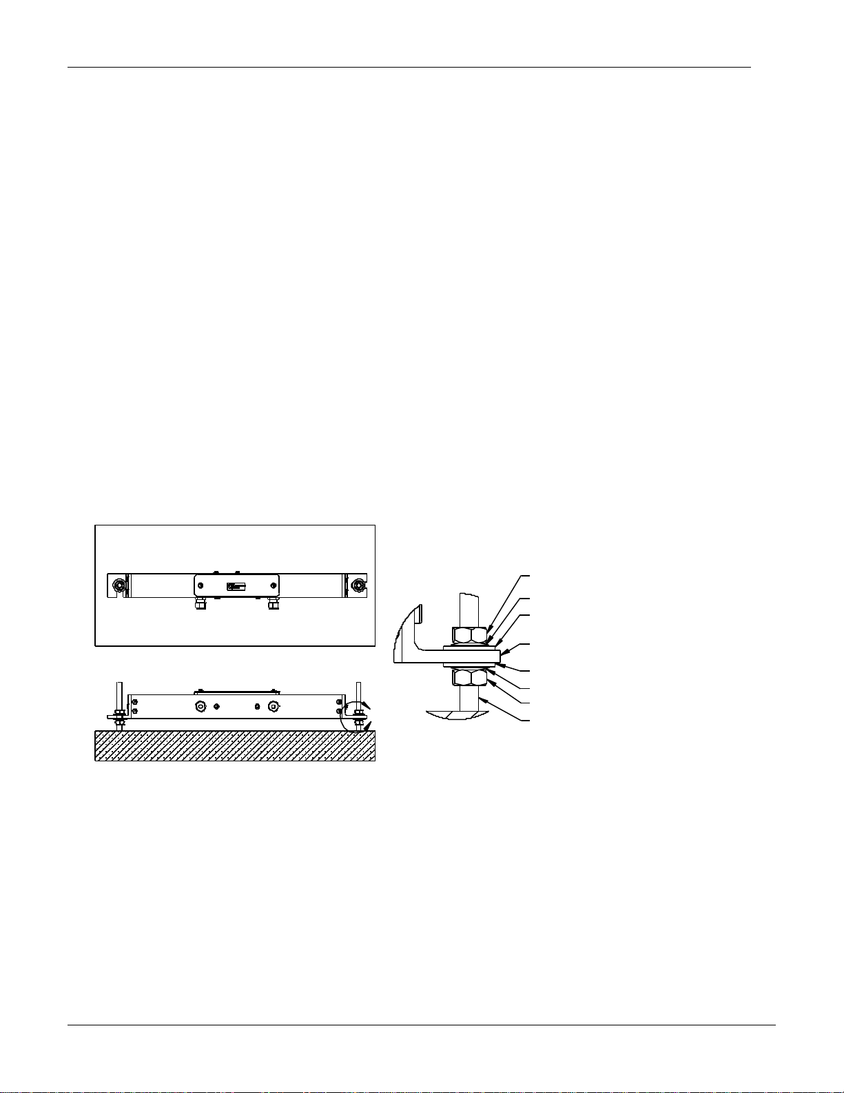
Figure 1: MEMS Tilt Beam
Figure 2: MEMS Tilt Beam Details
RST Instruments

MEMS Tilt Beam Instruction Manual
2
2 MATERIALS
2.1 REQUIRED TOOLS/COMPONENTS
Before beginning the installation of the Horizontal or Vertical MEMS Tilt Beam,
ensure that all of the components and tools required for installation are present. See
the list below for tools and equipment required for a typical installation:
MEMS Tilt Beam(s)
(1) Readout (IC6800-V, or FlexDaq 1000/800 Datalogger)
(1) Level
(1) Phillips screw driver
(1) Anchor kit (consisting of (2) 10mm SS anchors, (4) belleville washers, (4) nylon
washers, (2) nylon bushing, (4) 10mm SS nuts
(2) 16mm wrench
3 INSTALLATION
Determine the MEMS Tilt Beam installation location. The location must allow for
access inside the beam to connect the sensors after the unit has been mounted. The
mounting angles should be securely attached with the supplied hardware to a rigid
structure that is free of vibration. Care should be taken to avoid areas of rapid or
extreme changes in temperature such as direct sunlight or near heating or cooling
equipment. For exposed units, a sun shade and or external insulation is
recommended.
The output of the MEMS sensor(s) is in Volts, which can be read with an RST IC6800V Readout or a FlexDaq 1000/800 Datalogger. The MEMS sensors have excellent
zero and full scale stability. As a result, precision sensor zeroing is not necessary.
This is in contrast to electrolytic sensors which have high coefficients of thermal
sensitivity, necessitating precise leveling on the structure.
3.1 ANCHOR INSTALLATION
It is important to install the anchors at a distance equal to the MEMS Tilt Beam
mounting angles pattern (using a level, ensure the anchors are installed inline
horizontally or vertically) (see figure 3).
The anchors should:
1. Protruding horizontally, in all planes, from the structure (not necessarily
perpendicular to the structure)
RST Instruments

MEMS Tilt Beam Instruction Manual
3
FRONT VIEW
10mm CONCRETE
ANCHOR HOLES
TILT BEAM LENGTH
REQURED SPAN
ACCORDING TO
TOP VIEW
10mm CONCRETE
ANCHOR
SIDE VIEW
FRONT VIEW
10mm CONCRETE
ANCHOR HOLES
TILT BEAM LENGTH
REQURED SPAN
ACCORDING TO
SIDE VIEW
2. In plane (i.e. reading level, if a level were placed across both anchors)
3. Allow anchors to set.
Figure 3: Horizontal & Vertical Tilt Beam Concrete Anchor Orientation
RST Instruments

MEMS Tilt Beam Instruction Manual
4
Figure 4: MEMSTilt Beam/Meter General Arrangement
RST Instruments
MEMS Tilt Beam Instruction Manual
5
10mm NUT
10mm NUT
10mm BELLEVILLE WASHER
10mm NYLON WASHER
MOUNTING BRACKET
10mm NYLON WASHER
10mm BELLEVILLE WASHER
MEMS TILT BEAM
10mm CONCRETE ANCHOR
DETAIL A
SCALE 1 : 2
A
3.2 SINGLE MEMS TILT BEAM INSTALLATION
Determine the MEMS Tilt Beam installation orientation (i.e. Is the Beam to be
installed on the ceiling, wall, or floor). Refer to Figure 4 and adjust mounting
brackets accordingly.
1. Thread a 10mm nut onto each anchor until they reach the desired position
(ensure the nuts are in plane)
2. Place a Belleville washer over each anchor (see Figure 5)
3. Place a Nylon washer over each anchor
4. Place a Nylon bushing over each anchor
5. Slide the MEMS Tilt Beam onto the Nylon Bushings
6. Place a Nylon Washer over each anchor
7. Place a Belleville washer over each anchor (see Figure 5)
8. Thread a 10mm nut onto each anchor, finger tight, and ensure that the Beam is
horizontal or vertical
9. For a single beam installation, where (2) Belleville washers are used per
anchor, turn the nut 2-3 wrench flats (120-180) (see Figure 5)
10. For a double beam installation, where (4) Belleville washers are used per
anchor, turn the nut 4-5 wrench flats (240-300) (see Figure 5)
Figure 5: Single Beam Mounting Details
RST Instruments

MEMS Tilt Beam Instruction Manual
6
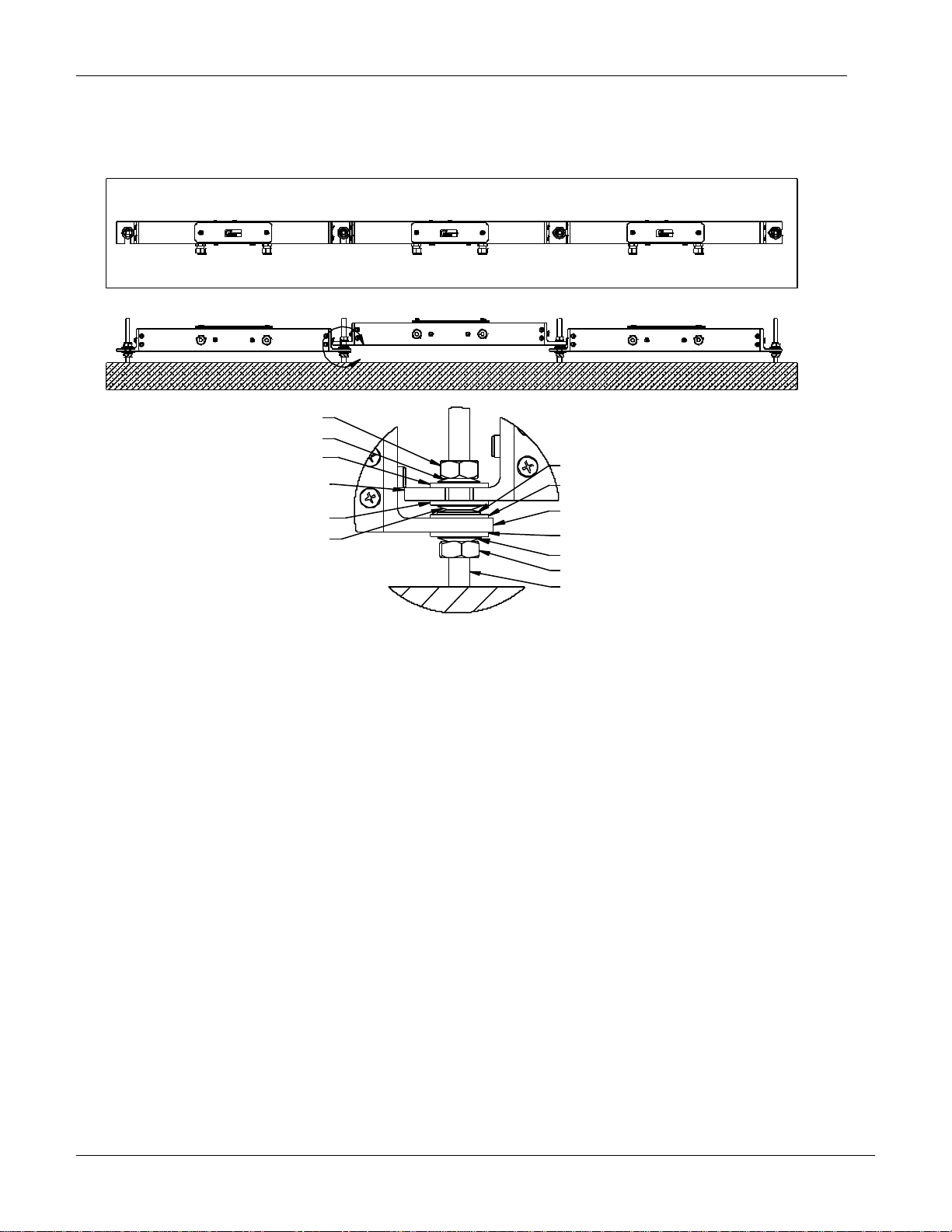
3.3 MULTIPLE MEMS TILT BEAM INSTALLATION
Determine the MEMS Tilt Beam installation orientation (i.e. Is the Beam to be
installed on the ceiling, wall, or floor). Refer to Figure 4 and adjust mounting brackets
accordingly. Ideally, the beams should be staggered (see Figure 6).
There are two ways to complete this installation:
Installing the odd beams first and then the even beams afterwards
Or, install one beam at a time in succession, by placing beams on top
and then in behind.
In either case, you should end up with a staggered installation as shown in Figure 6.
The following installation procedure is for installing one beam at a time in
succession.
1. Thread a 10mm nut onto the first two anchors until they reach the desired
position (ensure the nuts are in plane, not necessarily the same distance from
the wall as the wall may be bowed)
2. Place a Belleville washer over the 1st and 2nd anchors (see Figure 6)
3. Place a Nylon washer over the 1st and 2nd anchors
4. Place a Nylon bushing over the 1st and 2nd anchors
5. Slide the MEMS Tilt Beam onto the Nylon Bushings
6. Place a Nylon Washer over the 1st and 2nd anchors
7. Place a Belleville washer over the 1st and 2nd anchors (see Figure 5 or 6)
8. Thread a 10mm nut onto the 1st anchor, finger tight, and ensure that the Beam
is horizontal or vertical
9. Tighten the nut 2-3 wrench flats (120-180)
10. Thread a 10mm nut onto the 3rd anchor (position nut so that the next beam
when installed will be parallel to the previously installed beam (see Figure 6)
11. Place a Belleville washer and then a Nylon washer and Nylon Bushing over the
nut installed in step 10 (see Figure 6)
12. Place a Belleville washer and then a Nylon washer and Nylon Bushing over the
Belleville washer on the 2nd anchor (see Figure 6 for orientation of washers)
13. Slide the MEMS Tilt Beam onto the 2nd and 3rd anchors, adjust the nut on the 3rd
anchor until the beam is parallel
14. Place a Nylon Washer, and then a Belleville washer over the 2nd and 3rd anchor
15. Place a Nylon bushing over the 2nd and 3rd anchor
16. Thread a 10mm nut onto the 2nd anchor, finger tight, and ensure that the Beam
is horizontal or vertical
17. Tighten the nut 4-5 wrench flats (240-300)
18. Repeat steps 10-17 incrementing anchor references by 1 (i.e. in step 10, the 3rd
anchor would now become the 4th anchor etc.)
RST Instruments
MEMS Tilt Beam Instruction Manual
7
MOUNTING BRACKET
SCALE 1 : 2
DETAIL A
10mm NUT
10mm NYLON WASHER
MOUNTING BRACKET
10mm NYLON WASHER
10mm BELLEVILLE WASHER
10mm NUT
10mm CONCRETE ANCHOR
10mm BELLEVILLE WASHER
10mm BELLEVILLE WASHER
10mm NYLON WASHER
10mm NYLON WASHER
MEMS TILT BEAM
MEMS TILT BEAM
10mm BELLEVILLE WASHER
A
The beams when installed should be staggered and the washers and nuts should be
installed as shown in Figure 6.
Figure 6: Multiple Beam Configurations
RST Instruments
MEMS Tilt Beam Instruction Manual
8
Tiltmeter
Wire Color
Terminal
Datalogger
12V
Red
1
12V
Gnd
Black
2
Gnd
A+
Green
3
xH
A-
White
4
xL
B+
Orange
5
yH
B-
Blue
6
yL
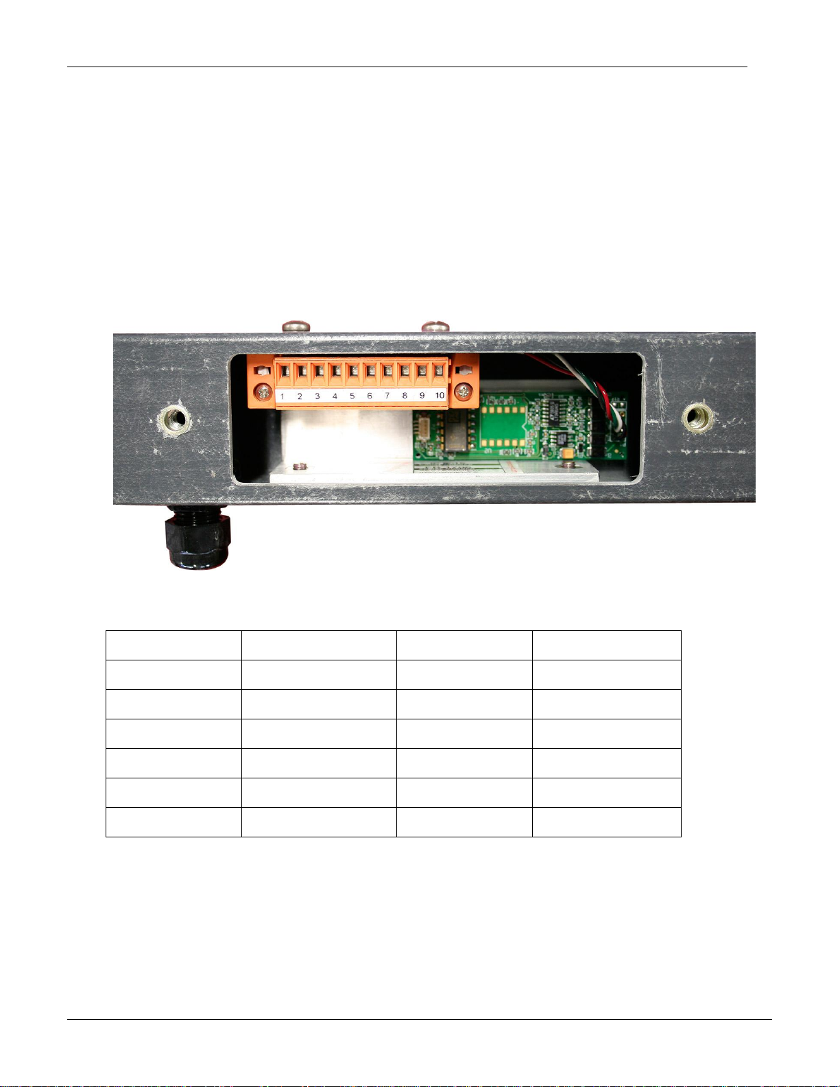
3.4 ELECTRICAL CONNECTIONS
1. Under the Colour Code Table, look up the lead designations for the type of
cable being used.
2. Under the Electrical Connections Table, make the appropriate lead connections,
according to the type of system being used.
3. Horizontal and Vertical Tilt Beam system measure the A-axis (Green & White).
Vertical Tile Beam system is capable of measuring the B-axis (optional) (Orange
& Blue).
Information regarding your sensor configuration and cable type is listed below and on
your Calibration Certificate.
Figure 7: Electrical Connections
Note: For BUSSED Systems only, use the cable with the jacket stripped 25mm back
for the Cable Output.
RST Instruments

MEMS Tilt Beam Instruction Manual
9
4 Analyzing the Data
Each MEMS Tilt Beam is identified by a Serial Number, and has a corresponding
Calibration Certificate (See Sample Calibration Certificate). To convert the sensor
signal into meaningful data, simply substitute the values from the readings and the
Calibration Constants into the following formula:
Sin = m(V-b)
Where
V is the Tiltmeter Output signal.
m is the predetermined Calibration Constant.
b is the predetermined Calibration Constant.
The sensing principle of the MEMS Tilt Beam is that of an accelerometer with the
sensitive axis is oriented horizontally. The measured phenomenon is then the
component of gravity transverse to the sensitive axis, i.e.
a = g sine()
Commonly, MEMS Tilt Beam data are interpreted as linear motion – i.e. rotation about
a presumed radius gives an equivalent motion. In many cases, where the ultimate
variable of interest is lateral displacement at some presumed radius due to rotation,
the accelerometer result can be simply rescaled, i.e.
x = r sine()
r a
= -----
g
In the case of a uniaxial MEMS Tilt Beam, radius (r) is the beam length. For MEMS Tilt
Beam on rigid bodies, the radius must be chosen with some care.
RST Instruments

MEMS Tilt Beam Instruction Manual
10
x
r a g
Figure 8: Tilt Data Interpretation
In cases where the actual angle is sought, the arcsine function or a polynomial
equivalent may be used:
= arcsine(a/g)
It should be noted that measuring “dynamic tilt” may be a concept error: the lateral
dynamic accelerations may exceed the tilt accelerations
RST Instruments

MEMS Tilt Beam Instruction Manual
11
Figure 9: MEMS Tiltbeam Directional Reading
RST Instruments

12
5.1 ENVIRONMENTAL
Operating temperature
-40C to +80C
5.2 ELECTRICAL
Sensor
0ne/Two MEMS Tilt Sensor(s)
Range
15 Degree Standard
Resolution
0.0013 Degree
Null Repeatability
<0.004 Degree
Signal Cable
22 Gauge Shielded Twisted
Datalogger
Analog Readout
FlexDaq 1000/800
IC6800-V
5 Specifications
MEMS Tilt Beam Instruction Manual
RST Instruments

MEMS Tilt Beam Instruction Manual
13
Figure 10: Calibration Certificate
RST Instruments
 Loading...