

Page 1

Quick Start
RSDPB5000/RSDPB4000
High Voltage Differential Probe Series
Page 2

2
Page 3

Please read this manual carefully before use
Safety precautions
1.
Be cautious of an electric shock
2.
Pay attention to the maximum input voltage
Please do not use in humid or in flammable and explosive environment
3
Page 4

Model
Maximum Input Voltage
Bandwidth
Attenuation Rate
RSDPB5150
1500V
70MHz
50X/500X
RSDPB5000 Series High Voltage Differential Probe
RSDPB5000 Series Summary
Overview
RSDPB5000 series high voltage differential probes are designed for the
measurement of high voltage differential signal, to meet the demand for floating
measurement. The bandwidth can be as high as 100MHz, meeting the demand for
majority of measurement systems.
There are a variety of ranges to choose from, and their differential voltage
measurement range can meet with the demand for majority of tested circuits. Users may
go into test mode to adjust the offset voltage, and also to adjust automatically to
prevent probes being disordered after years’ of use. The electronic touch buttons give
them a longer working life.
The function of 5MHz bandwidth limit selection, whose frequency bandwidth fits
the FETs switching frequency measurement in most switching power supplies, and they
can filter out higher frequency noise and interference. With the sound & light alarming
function, this can also be closed manually, with a USB power supply connector to make
it easier and more flexible for use. The probes are equipped with standard BNC input
connectors, they can be used with any manufacturer oscilloscope ( oscilloscope input
impedance should set to 1MΩ. when 50Ω is selected, the attenuation multiply
attenuates double.) to test waveform of the tested circuits, there is an automatic save
function, to prevent users re-operating in case of power supply drops. The probes have
good capability of common mode noise suppression and can be widely used in the
research and development, debugging or overhauling work for switching power supply,
frequency converter, electronic ballast, frequency conversion electronic appliances and
other electric power equipments.
Application
■ Floating voltage measurement
■ Frequency converter
■ Switching power supplies designs
■ Welding, plating power supplies
■ Induction heating, electromagnetic oven
■ Motor driven design
■ Electronic ballast design
■ CRT displayer design
■ Inverter, UPS power supplies
■ Frequency conversion electrical appliances
■ Power conversion and related design
■ Electrical engineering experiment
■ Low voltage appliances experiment
■ Power electronics and electric drive experiment
4
Page 5

Input Port
Maximum differential Voltage
1500V Danger! High Voltage!
Commom-mode Voltage Security
Level
Overrange Indicator
Attenuation Button
Attenuation Indicator
Bandwidth Limit Button
Bandwidth Limit Indicator
Audible Overrange Button
Audible Overrange ON/OFF
Indicator
Terminal Load
Power Interface: USB B
Output Interface: BNC
Product and Accessories Description
Probe body description
Take RSDPB5150 as an example, voltage, range and bandwidth are varied with different
products.
Detailed Description:
1.
output will reverse when is reversely connected. Use together with standard red black input
c a b l e s .
2.
500X indicate the maximum test voltage is 1500V.50X indicates the maximum test voltage is
150V. Oscilloscope attenuation factor should be set accordingly based on the probe
attenuation selection.
Input connector: Standard red and black socket. Red is positive, black negative,
ATTENUATION: Different attenuation indicates different ranges, such as RSDPB5150:
5
Page 6

3. BANDWIDTH: The series products have bandwidth selection function. The default is full
bandwidth(FULL) of the product. When testing low frequency signal, you can choose 5MHz
bandwidth limit to prevent being interfered by high frequency signal.
4. AUDIBLE OVERRANGE: When the test range exceeds probe range, audible and visual
alarm will start. The function is to control buzzer alarm on or off, ON is to open audible alarm and OFF
closes the alarm.
5. Output connector: Standard BNC input connectors, can be connected to any
Manufacturer oscilloscope, oscilloscope input impedance should set to 1MΩ.Ifset to 50Ω, the output
attenuation is a half of the practical value.
6. Power interface: Standard USB type B interface, supply power with standard USB adapter,
can be supplied by the oscilloscope, it can also be supplied by portable power source, convenient for
outdoor test.
7. Factory Setting: The default factory setting is high attenuation ratio, FULL
bandwidth, audible alarm is on. The product has an automatic memory; this will automatically save
the state before power off.
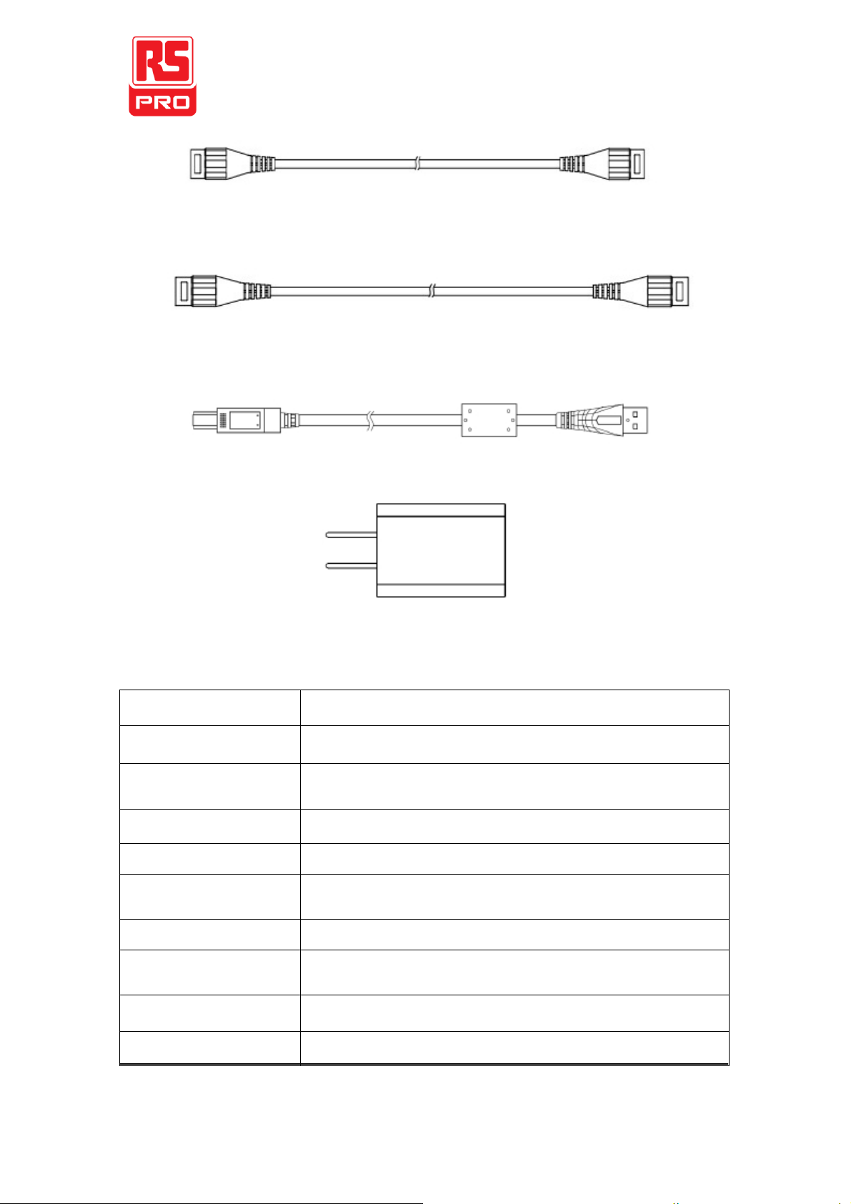
Accessories Description
Alligator Clips (CK-261 red black 1pair) Alligator Clips (CK-262 red black 1 pair)
Pincer Clips (CK-281 red black 1 pair) Hook Clips (CK-284 red black1 p a i r)
Input differential lead (CK-28 one pair)
6
Page 7
Model
RSDPB5150
Alligator Clips (CK-261)
CATIII 1000V
CATIV 600V
Alligator Clips (CK-262)
-----
Pincer Clips (CK-281 )
CATIII 1000V
Hook Clips (CK-284 )
CATIII 1000V
High Voltage Input
differential lead (CK-28)
10A CATIII 1000V
Coaxial Output Line (CK-310)
Double-ended BNC connector coaxial line 1m (Standard accessories)
Coaxial Output Line (CK-320)
Double-ended BNC connector coaxial line
2m (non-standard, purchased individually)
USB line(CK-315)
AM-BM, 1.5 m
Power adapter(CK-605)
USB 5V/1A
Coaxial Output Line (CK-310)
Coaxial Output Line (CK-320)
USB line (CK-315 AM-BM, 1.5m)
Power adapter (CK-605) USB 5V/1A
Product standard accessories description
7
Page 8

Model
RSDPB5150
BW(-3dB)
DC-70MHz
Rise time
≤5ns
Accuracy
±2%
Attenuation Rate
50X/500X
100X/1000X
Max Differential Test Voltage (DC + Peak AC)
50X:150V
100X:700V
500X:1500V
Max input common mode voltage( voltage-to-earth
Vrms)
600V CATIII
1000V CATII
Input Impedance
Single-ended to ground
5MΩ
Two inputs
10MΩ
Input Capacitance
Single-ended to ground
<4pF
Two inputs
<2pF
CMRR
DC
>80dB
100kHz
>60dB
1MHz
>50dB
Noise(Vrms)
50X: <50mV
500X: <50mV
100X: <200mV
1000X: <1.2V
Propagation delay (standard 1 m output lead)
18ns±1ns
Bandwidth limit(5MHz)
≥-3dB@5MHz
Differential overvoltage detection level
50X:≥150V
Overload indicator (red light)
YES
Overload Alarm
Yes(Can shut up manually)
Automatic Save
YES
Offset Setting function
Yes (Set in test mode)
Terminate Load
1MΩ
Power Supply
USB 5V/1A adapter
Electric Specification
8
Page 9

Model
RSDPB5150
Differential Input lead
CK-28
Approx 28 cm
Output Lead
CK-310
Approx 1 m
CK-320
Approx 2 m
Alligator Clips CK-261
Approx 85*40*17 mm
Alligator Clips CK-261
Approx 106*43*16 mm
Pincer Clips CK-281
Approx 152*50*13 mm
Hook Clips CK-284
Approx 121*23*23 mm
Probe body dimensions
195*65*28 mm
Probe body weight
Approx 188 g
Model
RSDPB5150
Operating Temperature
0~50℃
Non-operating
-30~70℃
Operating Humidity
≤85%RH
Non-operating Humidity
≤90%RH
Operating Altitude
3000m
Non-operating Altitude
12000m
Mechanical Specification
Environment Characteristics
9
Page 10

Operating the Probe Safely
1. You should estimate the tested voltage amplitude before testing, please do not use if
exceeds the voltage range, because it is likely the probe is damaged.
2. Connect the input lead and output lead to the probe, and then connect the probe to the
oscilloscope or other instruments.
3. Connect the power adapter to voltage probe, the power indicator light turns on green.
Please select proper range based on the tested voltage. When the tested voltage exceeds range,
the overload indicator light is on with alarming sound, which can be manually turned off.
4. Please set proper attenuation rate for the oscilloscope or other instruments according to
the probe range. And adjust the oscilloscope sensitivity based on the tested voltage.
5. Connect the probe clips based on needs, start after connecting to the circuits to be tested.
When testing, the probe body should be kept away from high voltage pulse circuits to reduce
interference to the probe.
Test Mode (Offset Setting)
Users may enter the test mode to adjust offset based on needs. The probes may be disordered
after years’ of use. The adjustment method is as follows if not at zero:
①Please press these two keys, and make short circuits for input terminals.
②Turn power on to start, entering test mode, and the overload indicator light is on,
release the two keys.
③Go into the high attenuation fact or offset adjustments under the state, press the
offset increase. Press offset decrease.
④After the adjustment, press key to switch to low attenuation ratio offset adjustment,
press key offset increases, press , offset dec re as es.
⑤Then press key to exit the test mode, offset adjustment is completed and the
overload indicator light is off, entering into normal operation mode.
Safety Notices
1. Please try to wind up the input leads when testing, this is better for eliminating noise and
to improve the ability of high frequency response. Please view below for the winding method:
10
Page 11

Equipments
Minimum Requirements
Usages
Oscilloscope
Bandwidth≥100MHZ.Accuracy≦1.5%,
e.g.: SO/DSO4000
Displays probe output
Test bandwidth.
Standard signal
Amplitude:accuracy≤0.75%.rise time≤3ns
AC accuracy.
Generator or calibrator
e.g.: FLUKE/WAVETEK 9100
Common mode rejection
Digital millimeter
Accuracy of not less than 6 and a half
e.g.:KEITHLEY 2000
Test the DC accuracy
Insulation pincer clips
Supplied in the accessories
Testing clips
BNC adapter 1
BNC-male-to-female-dual show as Figure 1
Test adapter
BNC adapter 2
BNC-male-to-dual binding post show
as Figure 2
Test adapter
BNC adapter 3
BNC-female-to-dual binding post show
as Figure3
Test adapter
Load terminal
BNC-male-to 50Ωload show as Figure 4
Signal source load
2. It is better not to extend input lead when testing; otherwise it may introduce
more noise. If extra extension lead is necessary, please ensure the extension leads are
the same length, and the input frequency is under 10MHz, errors may exist if exceeds
10MHzoutput.
HF transient response with (left) and without (right) extension leads
Performance Verification
The below operation is for performance verification of the electric specification, requirement
for test equipment is shown below:
Figure 1 BNC-male-
to
-female-dual
Figure 2 BNC-female-
to
-dual binding post
Figure 3 BNC-male-
to
-dual binding post
Figure 4 BNC-male-
to
50 Ω load
11
Page 12

Model
Attenuation
Rate
Signal source
output voltage
Probe expected
output voltage
RSDPB5150
50X
5V
100mV±2mV
500X
50V
100mV±2mV
Model
Attenuation
Rate
Signal source voltage,
frequency setting
Expected probe
Rise time
RSDPB5150
50X
20Vpp,70MHz
≤5ns
500X
20Vpp,70MHz
≤5ns
Setup
1) Connect power adapter to voltage probe, which turns on green light, to ensure accuracy, test
the probe index after 20minutes.
2) Uncover the red black plastic cover of the BNC-male-to-dual binding post.
DC Accuracy
1) Connect the probe output to the BNC-female-to-dual binding post; plug the two input
terminals of the digital multi-meter into the binding posthole.
2) Connect the probe input to insulation pincer clips, and then connect the calibrator output
and the generator closed, connect the red clip to the positive pole, black clip to negative pole.
3) Set the probe attenuation factor in the first gear.
4) Follow the chart below to set output values for the signal source.
5) Enable the signal output, observe and record the output voltage for the attenuation.
6) Close the signal source output.
7) Switch the probe attenuation factor to the second gear.
8) Repeat step 4~6, and calculate whether is within the accuracy ranges.
Rise Time
1) Configure the fast rise output of the generator for a 50 Ω load. Attach a 50 Ω terminator
to the generator fast-rise output and attach the modified BNC adapter to the terminator.
Attach the differential probe input leads (without attachment accessories) by sliding the banana
plug of the leads onto the binding posts metal sleeves on the modified BNC adapter.
2) Connect the probe output to the oscilloscope, set attenuation factor in the first gear.
3) Refer to the below stable to set standard signal generator.
4) Enable signal source output and record the rise time.
5) Close signal source output.
6) Switch the probe attenuation factor to the second gear.
7) Repeat step 3-5, and calculate whether is in the range.
12
Page 13

Model
Attenuation
Rate
Probe expected output
voltage
RSDPB5150
50X
≤1mV
DC Common Mode Rejection Ration (CMRR)
1. Set RDPB5000 series probes at low attenuation ration, respectively (10X, 50X,100X).
2. Set 500V DC voltage for signal source, now the voltage output shutoff.
3. Connect the two probe inputs to 500Vvoltage.
4. Connect the probe output to BNC-female- to- dual binding post, and plug into the two
inputs of the digital millimeter.
5. Enable signal source output, respectively record voltage output values; check with the
following chart to calculate whether is within the ranges.
6. Close the calibrator after completion of the test.
Note: High voltage500 V is used during the testing, please pay attention to personal
safety, to reduce voltage fluctuation, be sure to make the calibrator output 500 V high
voltages after the completion of all connections.
13
Page 14

Model
Maximum Input Voltage
Bandwidth
Attenuation Rate
RSDPB4080
800V
50MHz
10X/100X
RSDPB4080 High Voltage Differential Probe
RSDPB4080 Summary
Overview
The RSPDB4080 differential probe provides a safety means for measuring differential
voltage to all models of oscilloscopes. It can convert the high differential voltage (≤800Vpeak)
into a low voltage (≤8V) and display this on the oscilloscope. Its bandwidth is up to 50MHz,
which is ideal for large power testing, development and maintenance.
The RDPB4080 is designed to operate with the 1MΩ impedance oscilloscopes. When
combined with the 50Ω load, the attenuation will be 2 times as much.
RDPB4080 is recommend for use with our own manufactured PL-10 to expand the
measuring with the electricity meter to observe more accurate measurement. The accuracy of
oscilloscope is 1% and the electricity meter is about10%.
Electric Specification
(1) Bandwidth:DC-50MHz
(2) Attenuation: X100,X10
(3) Accuracy:+/-1%
(4) Input voltage range (DC+AC PEAK TOPEAK)
≤+/-80Vforx10, (about 30V RMS or DC)
≤+/-800Vforx100, (about 290V RMS or DC)
(5) Permitted max input voltage:
Max differential voltage: 800V (DC+AC PEAK TO PEAK)
Max voltage between each input terminal and ground: 800V RMS
(6)Input Impedance: Differential: 54MΩ/1.2pF
Between terminal and ground: 27MΩ /2.3pF
(7)Output voltage:≤+/-8V
(8)Output impedance:50Ω
14
Page 15

Reference
Use
Storage
Temperature
+20℃~+30℃
0℃~+50℃
-30℃~+70℃
Relative Humidity
≤70%RH
10%~85%RH
10%~90%RH
Attenuation Rate
X100
X10
Input Voltage(DC+AC Peak)
±800V
±80V
Operating environmental conditions
(1) Dimensions and weight:69x26x165mm.500g
(2) Electrical safety to IEC 1010-1 Dual insulation
Installation category Ⅲ
Degree of Pollution 2
Related voltage or max line-earth:6500V RMS CE:EN50081-1 and 50082-1
Operating procedure
Connect the probe to the oscilloscope with the BP-250 BNC TO BNC cable. Adjust the vertical
zero adjustment of the oscilloscope if necessary.
Select the attenuation rate and the vertical deviation of the oscilloscope in accordance with the
conversion table below.
Note: The power must be on
Attention: The real vertical deviation is equal to the attenuation rate multiplied by the
range of vertical deviation selected on the oscilloscope. It will be double in the case of a 50Ω
load.
15
Page 16

Care and Maintenance
1. Keep the probe clean and dry.
2. Please wipe with soft dry cloth to clean. Chemical must not be used to clean.
3. Please put the probe in the package provided, and put it in cool, clean and dry places.
4. Please put the probe in the package provided to prevent shock.
5. Do not forcefully pull the input and output lead to prevent bending, twisted and folding.
16
 Loading...