


Instruction Manual
IM-195
3-Axis RF Field Strength Meter

3-Axis RF Field Strength Meter/ English
2017-10-25 V002 EN-1
Contents
Introduction EN-2
Features EN-3
General Specification EN-3
Instrument Description EN-4
LCD description EN-5
Safety EN-6
Operation EN-6
Battery Replacement EN-15
Limited Warranty EN-15
Contact information EN-16

3-Axis RF Field Strength Meter/ English
EN-2 2017-10-25 V002
Introduction:
IM-195 is designed for measuring Radio Frequency (RF)
electromagnetic field strength and the monitor range is from
50MHz to 3.5GHz with triple axis X, Y and Z isotropic sensors.
It is used to indicate electromagnetic pollution generated by
cellular phone tower antenna, wireless internet, microwave
ovens, cellular phones and cordless phones, etc.
With its simple method of operation this meter will measure
electromagnetic pollution generated artificially. Wherever there
is a voltage or a current, electric (E) and magnetic (H) fields
arise. All types of radio broadcasting and TV transmitters
produce electromagnetic fields. They also arise in industry,
business and the home.
Electric field strength (E):
A field vector quantity that represents the force (F) on an
infinitesimal unit positive test charge (q) at a point divided by
that charge. Electric field strength is expressed in units of volts
per meter (mV/m). This meter measures electric field strength
directly.
Magnetic field strength (H):
A field vector that is equal to the magnetic flux density divided
by the permeability of the medium, magnetic field strength is
expressed in units of amperes per meter (A/m). In far field
situations, one can calculate the magnetic field from the electric
field value. This meter can display the calculated Magnetic field
strength.
Power density (S):
Power per unit area perpendicular to the direction of
propagation usually expressed in units of Watts per square
meter (W/m2) or, for convenience, units such as mili/Watts per
square centimeter (mW/cm2).
The characteristic of electromagnetic fields:

3-Axis RF Field Strength Meter/ English
2017-10-25 V002 EN-3
Electromagnetic fields propagate as waves and travel at the
speed of light (C). The wavelength is proportional to the
frequency:
(Wavelength) = C (speed of light) / f (frequency)
If the distance to the field source is less than three wavelengths,
then we are usually in the near field.
If the distance is more than three wavelengths, the far-field
conditions usually hold. In near field conditions, the magnetic
field value cannot be calculated from the electric field value.
This meter is designed for reliable far field measurements
only.
Features:
The auto-ranging units of measurement and the
measurement types have been selected to expressed in
units of electrical and magnetic field strength and power
density.
Non-directional (isotropic) measurement with three-axis
measurement sensor.
Selectable display functions of the instantaneous value, the
maximum value measured or the average value.
Configurable alarm threshold function.
This meter is capable of recording 200 measurements.
Low battery and over load indications
General specification:
Display:
LCD display with maximum reading
of 3999.
Sampling Rate:
2.5 times per second.
Sensor:
Triple axis.
Frequency Range:
50MHz to 3.5GHz.
Accuracy:
±1 dB at 2.45GHz.
Measurement Units:
mV/m, V/m, µA/m or mA/m,
µW/m2 , mW/m2 , µW/cm2.

3-Axis RF Field Strength Meter/ English
EN-4 2017-10-25 V002
Specified measurement range:
1. CW signal (f >50MHz) :
38mV/m to 11.00V/m, 53.0uA/m ~ 29.28mA/m ,
0.01uW/m2 ~ 323.3mW/m², 0.001uW/cm2 ~
32.33uW/cm2
2. Dynamic range: Typically 75dB.
3. Absolute error at 1V/m and 2.45GHz: ±1.0 dB.
Frequency response :
1. Sensor taking into account the typical CAL factor :
±2.4dB (50 MHz to 1.9 GHz).
±1.0 dB (1.9 GHz to 3.5GHz).
2. Isotropy deviation: Typically ±1.0 dB (2.45GHz).
3. Overload limit: 32.33uW/cm2 (11 V/m) per axis.
4. Overload limit (0 to 50°C): ±0.2dB.
Power Supply:
9V NEDA 1604, IEC 6F22,
JIS 006 P. battery x 1pc.
Battery life:
About 15 hours
Dimension:
55mm x 38mmx 195mm (LxWXH)
Weight:
Approx. 200g with battery installed
Accessories:
Manual, 9V battery and carrying bag.
Instrument description:
1. RF sensor (Triple-axis).
2. LCD.
3. MAX/ AVG/ ()
4. Record / Time/ ().
5. Power on/off.
6. Unit/ Enter.
7. Hold/ ALARM / ().
8. Backlight/ Set
9. XYZ/ MEM ().
10. Protection holster.
11. Tripod mounting screw.
12. Battery cover.

3-Axis RF Field Strength Meter/ English
2017-10-25 V002 EN-5
LCD description:
1. Primary display
2. Hold
3. Analogue bar graph
4. MAX
5. AVG
6. Low battery
7. x1x10x100
8. X.Y.Z
9. ALARM
10. mV/m, V/m(E)
11. µA/m, mA/m (H)
12. µW/m, µW/cm2 unit
13. E symbol
14. Auto power off
15. Time unit
16. MEM reading
17. SET
18. REC
19. CAL
20. Secondary Display
21. Buzzer
22. Decimal point
3-Axis RF Field Strength Meter/ English
EN-6 2017-10-25 V002
Safety:
CAUTION
Be extremely careful for the following
conditions while measuring.
Do not operate the meter in the environment with explosive
gas (material), combustible gas (material) steam or filled
with dust.
In order to avoid reading incorrect data, please replace
the battery immediately when the symbol appears on
the LCD.
In order to avoid the damage caused by contamination or
static electricity, do not touch the circuit board before you
take any adequate action.
Operating Environment is for indoors use only. The meter
was designed for being used in an environment of pollution
degree 2.
Operation Altitude: Up to 2000M.
Operating Temperature & Humidity: 0°C ~ 50°C, 25%~
75%RH.
Storage Temperature & Humidity: -10°C ~ 60°C, 0%~
80%RH.
Operation:
1. Press to turn the power on or off.
2. Turn the meter on; press repeatedly to select the
displayed value of XYZ (all axes).
3. Position the sensor of the meter to RF strength source
and hold the meter steady during the measurement.
4. The LCD displays the measured value.
5. Press repeatedly to select the desired unit to be
shown on the LCD (we recommend using mV/m).
6. After the testing, turn the meter off.

3-Axis RF Field Strength Meter/ English
2017-10-25 V002 EN-7
Important:
If the sensor is moved quickly, excessive field strength values
could be displayed. This effect is caused by electrostatic
charges.
Short-term measurements
Use either the “instantaneous” or the “Max instantaneous”
mode, if the characteristics and orientation of the field are
unknown when entering an area exposed to electromagnetic
radiation.
Hold the meter at arm’s length.
Make several measurements at various locations around your
work place or the interested areas as described above. This is
particularly important if the field conditions are unknown and
possibly dangerous.
Pay special attention to measuring the vicinity of possible
radiation sources. Apart from active sources, those
components connected to a source may also act as radiators.
For example, the cables used in diathermy equipment may
also radiate electromagnetic energy. Note that metallic objects
within the field may locally concentrate or amplify the field
from a distant source.
Long-term exposure measurements
Place the meter between yourself and the suspected source
of radiation. Make measurements at those points where parts
of your body are nearest to the source of radiation.
Note: Use the Average or Max average modes only when the
instantaneous measurement values are fluctuating greatly.
You may fix the meter to a wooden or plastic tripod.
HOLD
Freezes the reading present on the LCD at the moment
when is pressed and LCD shows HOLD. Press
again to disable data hold.

3-Axis RF Field Strength Meter/ English
EN-8 2017-10-25 V002
UNIT
Press repeatedly to change the units of mV/m (V/m),
µA/m (mA/m), µW/m2 (mW/m2) or µW/cm2.
Electric field strength (V/m)
Computed magnetic field strength (mA/m)
Computed power density (mW/m2)
Computed power density (μW/cm2)
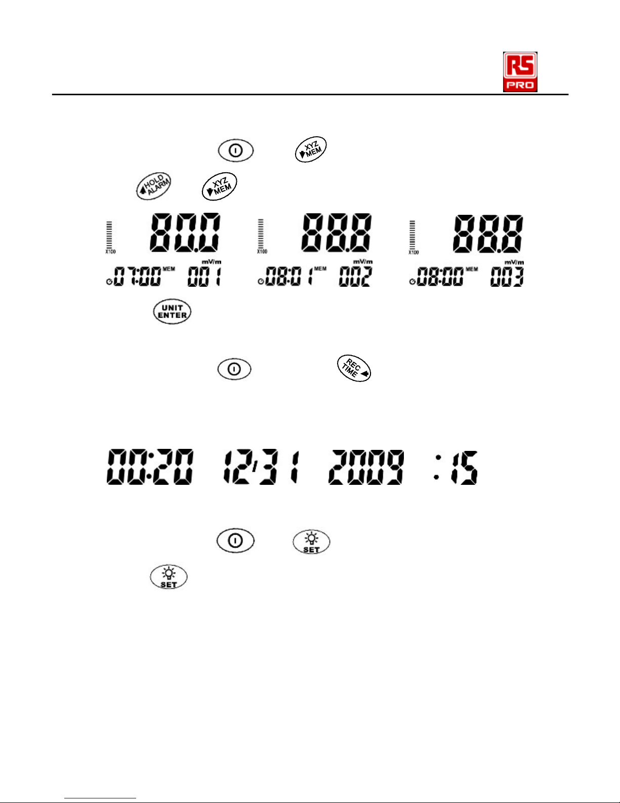
MAX / AVG
Press repeatedly to select the displayed reading from
MAX to AVG to MAX/AVG and back to MAX.
Press and hold for more than 3 seconds to disable this
function.
The maximum averaging storage is up to 99 minutes and 99
seconds. After this period of time, updating will stop
automatically and the LCD displays .
The following graph shows of Instantaneous (actual), MAX
(hold), AVG and MAX/AVG:

3-Axis RF Field Strength Meter/ English
2017-10-25 V002 EN-9
REC
Press to save the current measured result in meter’s
memory; the LCD shows REC with a number 001 to 200.
The meter records up to 200 data sets.
Over load indication shows:
XYZ
Press repeatedly to select the sensor axis:
All axis XYZ → X axis → Y axis → Z axis
Backlit
Press to turn the backlit on. Press this button to turn the
backlit off. To save the battery life, the meter automatically
turns the backlit off after 30 seconds.
ALAM (alarm)
Press and hold and together to switch the alarm
function on, the display shows ALAM. To switch the alarm
function off, repeat this process.
When the alarm sounds, the display shows .
3-Axis RF Field Strength Meter/ English
EN-10 2017-10-25 V002
MEM (view the saved data)
Press and hold and together to view the saved
data.
Use or to view the next or previous records.
Press to exit this mode.
TIME
Press and hold , and press repeatedly to display
the time method of the Year, Month, Date, Hour and Second.
This meter’s clock uses 24 hour time setting.
Default time mode setting is “2010/01/07 00 : 02” “:00”.
SET
Press and hold and together to enter the setup
mode.
Press to scroll through the setup function.
There are 6 functions in the setup mode:
1. Clock setup.
2. Setting the alarm limit value (ALARM).
3. Clear all data memory.
4. Analogue bar graph x1 x10 x100.
5. Auto power off time.
6. Setting the calibration factor (CAL).
3-Axis RF Field Strength Meter/ English
2017-10-25 V002 EN-11
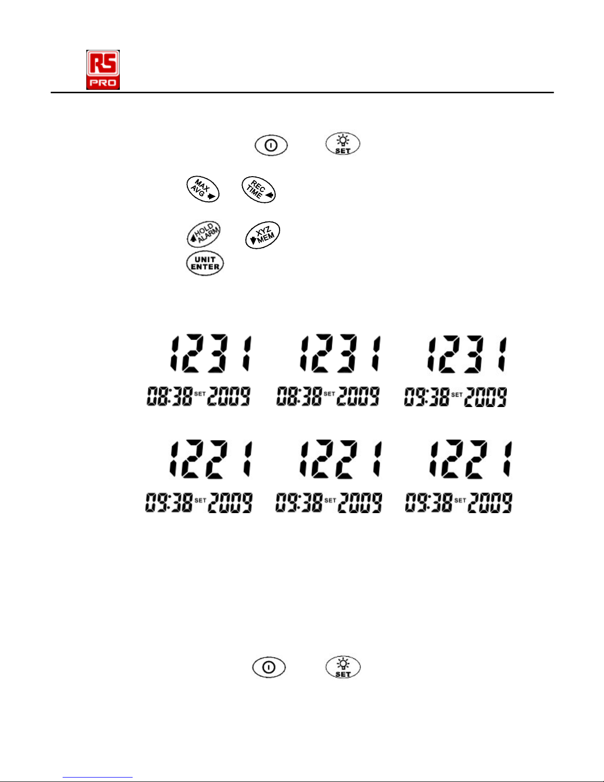
1. Clock setup:
Press and hold and together to enter the
first setup function. The clock is 24 hour time setting.
Press or to select desired digit (hour→
minute year→ month→ day).
Press or to change the value.
Press to save the setting and exit the SET mode.
Date/time default format: 2009/12/21 12:12.
Year format: 2000 ~2099 display as 00 ~ 99.
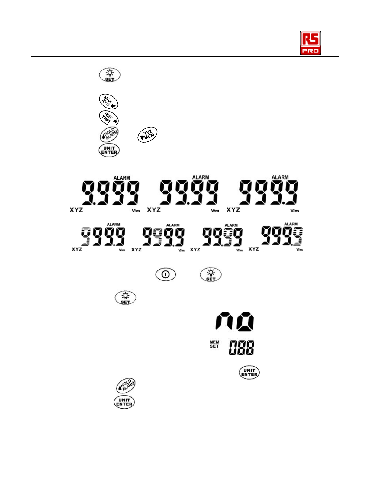
2. Setting the alarm limit value (ALARM).
The alarm limit value determines the level at which the
alarm will sound. The alarm limit value can be edited
only in the V/m unit; the setting range is from 0.001 to
999.9 V/m. The ALARM default is set at 999.9 V/m.
Alarm limit function is only used for the total of three
axial values.
Press and hold and together to enter the
setup mode.
3-Axis RF Field Strength Meter/ English
EN-12 2017-10-25 V002
Press 1 more time to enter the alarm setting function,
the readout value is flashing and V/m unit is displayed.
Press to move decimal.
Press to select the desired digit.
Press or to change the value.
Press to store the new setting value and exit the SET
mode.
3. Clear data
Press and hold and together to enter the
setup mode.
Press button 2 more times to enter clear data
function, the display shows:
To exit without clearing data, press .
Press to select “YES”.
Press to clear all the data in the memory and exit
the SET mode.

3-Axis RF Field Strength Meter/ English
2017-10-25 V002 EN-13
4. Analog bar graph x1 x10 x100.
Press and hold and together to enter the
setup mode.
Press button 3 more times to enter the analogue
bar graph setting mode.
The bar graph symbol is flashing. The current setting of
x1, x10, or x100 is displayed at bottom of graph. X1 is
normal setting. X10 is 10 times more sensitive, x100 is
100 times more sensitive.
Press to increase the sensitivity or to
reduce the sensitivity.
Press to save the setting and exit the SET mode.
5. Auto power off time
Press and hold and together to enter the
setup mode.
Press button 4 more times to enter the auto
power off setting mode.
Press and button to change the value. The
auto power off time default setting is 15 minutes.
Press to save the new setting value and exit the
SET mode. The symbol is displayed. The maximum
auto power off time setting is 99 minutes.
Set the value to :00 to disable auto power off, the
symbol is not displayed.

3-Axis RF Field Strength Meter/ English
EN-14 2017-10-25 V002
5. Setting the calibration factor (CAL)
Press and hold and together to enter the
setup mode.
Press button 5 more times to enter the calibration
factor setting mode.
The“CAL”is shown at the center bottom of the
display. The CAL setting range is from 0.10 to 9.99.
The default setting is 1.00, which is appropriate for most
situations.
Press or to select the desired digit.
Press or to change the digit.
Press to save the new setting value and exit the
SET mode.
NOTE:
The calibration factor CAL serves to calibrate the
display for a specific frequency when the frequency of a
single signal is known. The field strength value
measured internally is multiplied by the value of CAL
that has been entered andthe resulting value is
displayed. The CAL factor is often used as a means of
entering the sensitivity of the field sensor in terms of its
frequency response in order to improve measurement
accuracy.
3-Axis RF Field Strength Meter/ English
2017-10-25 V002 EN-15
Battery Replacement:
The meter is powered by 9V battery x 1pc.
Use the following procedure to replace the battery:
1. Replace battery immediately when the LCD
displays .
2. Turn the meter off and remove the battery cover.
3. Replace with the new battery; take care to note the correct
polarity.
4. Re-install the battery cover.
Limited Warranty:
This meter is warranted to the original purchaser against
defects in material and workmanship for 3 year from the
date of purchase. During this warranty period, RS
Components will, at its option, replace or repair the
defective unit, subject to verification of the defect or
malfunction. This warranty does not cover fuses, disposable
batteries, or damage from abuse, neglect, accident,
unauthorized repair, alteration, contamination, or abnormal
conditions of operation or handling.
Any implied warranties arising out of the sale of this product,
including but not limited to implied warranties of
merchantability and fitness for a particular purpose, are
limited to the above. RS Components shall not be liable for
loss of use of the instrument or other incidental or
consequential damages, expenses, or economic loss, or for
any claim or claims for such damage, expense or economic
loss. Some states or countries laws vary, so the above
limitations or exclusions may not apply to you. For full terms
and conditions, refer to the RS website.
3-Axis RF Field Strength Meter/ English
EN-16 2017-10-25 V002
Contact information:
Africa
RS Components SA
P.O. Box 12182,
Vorna Valley, 1686
20 Indianapolis Street,
Kyalami Business Park,
Kyalami, Midrand
South Africa
www.rs-components.com
Asia
RS Components Ltd
Suite 1601, Level 16,
Tower 1,
Kowloon Commerce
Centre,
51 Kwai Cheong Road,
Kwai Chung, Hong Kong
www.rs-components.com
China
RS Components Ltd.
Suite 23 A-C
East Sea Business
Centre
Phase 2
No. 618 Yan'an Eastern
Road
Shanghai, 200001
China
www.rs-components.com
Europe
RS Components Ltd.
PO Box 99, Corby,
Northants.
NN17 9RS
United Kingdom
www.rs-components.com
Japan
RS Components Ltd.
West Tower (12th Floor),
Yokohama Business
Park,
134 Godocho, Hodogaya,
Yokohama, Kanagawa
240-0005
Japan
www.rs-components.com
U.S.A
Allied Electronics
7151 Jack Newell Blvd. S.
Fort Worth,
Texas 76118
U.S.A.
www.alliedelec.com
South America
RS Componentes
Limitada
Av. Pdte. Eduardo Frei M.
6001-71
Centro Empresas El
Cortijo
Conchali, Santiago, Chile
www.rs-components.com
 Loading...