


Instruction Manual
ICM 134
Clamp Meter
EN DE ES IT FR

EN - 2
Safety Information
Read and understand this Instruction
Manual completely before using this
instrument. Failure to observe the warnings
and cautions in this Instruction Manual may
result in injury or death, or damage to the
instrument and other equipment or
property.
If this instrument is used in a manner not
specified in these instructions, the protection provided by the instrument may be
impaired.
WARNING
- Examine the instrument and probes and
leads before use. Do not use the instru ment if it is wet or damaged, or if you
suspect it is not operating correctly.
- When using the instrument, test leads or
probes, keep your fingers behind the
finger guards.
- Remove the test lead from the instrument
before opening the battery cover or instru ment case.
- Always use the correct terminals, switch
position and range for measurements.
- Verify the instrument is operating correctly
by measuring a known voltage before
use. If in doubt, have the instrument
serviced.
- Do not apply more than the rated voltage
as marked on the instrument between
terminals, or between any terminal and
earth ground.
- Use caution when measuring voltages
above 30 Vac rms or 60 Vdc. These
voltages pose a shock hazard.
- To avoid incorrect readings that can lead
to electric shock, replace the battery as
soon as low battery indicator appears
in the display.
- Disconnect the circuit power and
discharge all high-voltage capacitors
before making resistance, continuity, or
diode measurements.
- Do not use the instrument in a Hazardous
Area or around explosive gasses or
vapours.

EN - 3
- Wear suitable Personal Protective
Equipment when working around or near
hazardous Live conductors which could
be accessible.
- Do not use the thermocouple to measure
the temperature of Hazardous Live
conductors or equipment.
Caution
- Disconnect the test leads from the test
points before changing the position of the
function rotary switch.
- Never connect the instrument to a source
of voltage with the function rotary switch in
Ω/ ;/ A position.
- If possible, do not work alone, so
assistance can be given if required.
- Do not expose the instrument to extremes
of temperature or high humidity.
- If this instrument is used in the vicinity of
equipment which generates electro
magnetic interference, the display may
become unstable or the measurements
may be subject to large errors.
The following symbols may appear on
the instrument and in this Instruction
Manual:
Risk of electric shock
Refer to Instruction Manual
Direct Current (dc)
Alternating Current (ac)
<
Battery
Earth
Equipment protected throughout by
double or reinforced insulation
Conforms to EU directives
Dispose of this equipment in
accordance with local regulations.
E
Application around and removal
from hazardous Live conductors is
permitted.

EN - 4
Maintenance
Do not attempt to repair this Instrument. It
contains no user-serviceable parts. Repair
or servicing should only be performed by
qualified personnel. This instrument
should be calibrated yearly, or more
frequently if used in harsh conditions or if
it is suspected of being inaccurate.
For calibration and repair contact RS
Components - the address is given at the
end of these instructions.
Cleaning
Periodically wipe the case with a damp
cloth and detergent. Do not use abrasives
or solvents.

EN - 5
To conserve battery power, the Auto Power
-off function will turn the instrument off
approximately 10 minutes after the last
operation.
10min
To disable the Auto Power-off function:
Turn the instrument off, press and hold the
“Backlight” button and turn the rotary switch
to the required function. The auto Power-off
is disabled until the next time the instrument is turned off and on again.
Power On / Off
Auto Power Off

EN - 6
ACV / DCV
Resistance

EN - 7
Diode / Continuity
;

EN - 8
DC µA
Capacitance
Note – To improve the measurement
accuracy of a small value capacitor, record
the reading with the test leads open circuit,
then substract the residual capacitance of
the Instrument and leads from the final
measurement.
C
UNKNOWN
= C
MEASUREMENT
- C
RESIDUAL

EN - 9
Temperature
Data Hold
392A
0A

EN - 10
ACA
392A
CAT.Ⅲ.600V
with respect to
earth for the jaw.
Tactile Barrier for
hand guard.
Do not hold
the meter across
the Tactile Barrier.
I
I
I
I
OK
OK
OK
I + (-I) = 0
Back Light

EN - 11
Specifications
1-1 General Specifications
LCD display digits :
3 3/4 digit large scale Liquid Crystal Display.
Display resolution : 4000 counts.
Measurement rate : 1.5 times / sec.
Overrange display :
“OL” is displayed for "Ω" functions,
The real value is shown for the "A" ,"V" and
"°C/°F " function.
Automatic power-off time : Approximately
10 minutes after last operation.
Low battery indicator : < is displayed.
Power requirement : 9V battery Type
6LR61, IEC6F22 or equivalent)
Battery life : Approximately 200 hours with
Alkaline battery.
1-2 Environmental Conditions
Indoor Use only.
Calibration : One year calibration cycle.
Operating temperature :
0°C to 30°C (32°F to 86°F) @ ≦ 80% RH
30°C to 40°C (86°F to 104°F) @≦ 75% RH)
40°C to 50°C (104°F to 122°F) ≦45%RH
Storage temperature : -20 to + 60°C
(-4°F to 140°F) @ 0 to 80% RH with
batteries removed from the instrument.
Measurement Category (Installation
Category) :
per IEC 61010-1:2001: CAT.Ⅲ 600V
Pollution Degree 2
Measurement Category l is for measurements performed on circuits not directly
connected to mains. Examples include :
Measurements on battery powered equipment and specially protected (internal)
mains-derived circuits.
Measurement Category ll is for measurements on circuits directly connected to the
low voltage installation. Examples include :
Household appliances, portable tools and
similar equipment.

EN - 12
Measurement Category lll is for measurements performed in the building installation.
Examples include measurements on
distribution boards, junction boxes, socketoutlets and wiring and cables in the fixed
installation.
Measurement Category lV is for measurements performed at the source of the
low-voltage installation. Examples include
measurements on primary overcurrent
protection devices and electricity meters.
Operating altitude : 2000m (6562 ft)
Conductor Size : 32mm diameter.
EMC : EN 61326-1
Shock vibration: Sinusoidal vibration per
MIL-T-28800E (5 to 55 Hz, 3g maximum).
Drop Protection : 1 metre drop onto
hardwood or concrete floor.

EN - 13
1-3 Electrical Specifications
Accuracy is ±(% reading + number of
digits) at 23°C (73.4°F) ± 5°C (± 9°F)
< 80%RH.
Temperature coefficient :
Add 0.2 x (Specified accuracy) / °C (1.8°F),
< 18°C > 28°C (< 64.4°F >82.4°F).
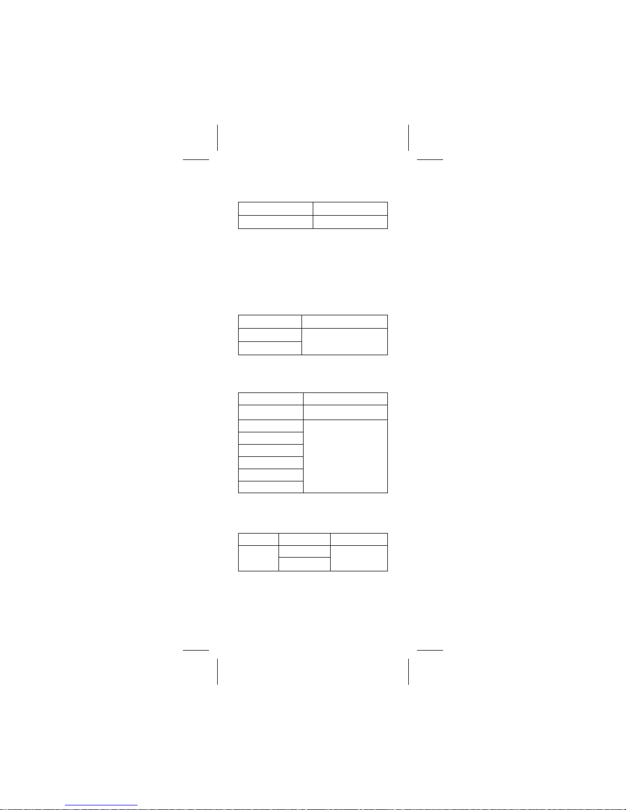
DC / AC Volts
Range DC Accuracy AC Accuracy
4.000V
±(0.9% + 2dgt)
±(1.5% + 5dgt)
50Hz ~ 500Hz
40.00V
400.0V
DC1000V
AC750V
Over voltage protection :
DC 1000 V or AC 750 V
Input Impedance :
10MΩ // less than 100pF.
CMRR / NMRR :
(Common Mode Rejection Ratio)
(Normal Mode Rejection Ratio)
V
AC
: CMRR > 60dB at DC, 50Hz / 60Hz
V
DC
: CMRR > 100dB at DC, 50Hz / 60Hz
NMRR > 50dB at DC, 50Hz / 60Hz
AC Conversion Type :
Average sensing rms indication.
Resistance
Range Accuracy
400.0 Ω *2 ±(1.0% + 2 dgt)
4.000 KΩ
±(0.7% + 2 dgt)
40.00 KΩ
400.0 KΩ
4.000MΩ
±(1.0% + 2 dgt)
40.00 MΩ *1
±(1.5% + 2 dgt)
Overload protection : 600Vrms
Open circuit Voltage : -1.3V approx.
* 1 < 100 dgt rolling.
* 2 < 10 dgt rolling.
EN - 14
Diode Check and Continuity
Resolution Accuracy
10 mV
±(1.5%+5 dgt)*
* For 0.4V ~ 0.8V
Max.Test Current : 1.5mA
Max. Open Circuit Voltage : 3V
Overload Protection : 600Vrms
Continuity : The built-in buzzer sounds
when the resistance is less than approximately 100Ω. The response time is
approximately 100 msec.
DC µA
Range Accuracy
400.0 µA
±(1%+2 dgt)*
4000 µA
Voltage barden : < 5mV / µA
Overload Protection : 600Vrms
Capacitance
Range Accuracy
4.000nF
±(3.0% + 20 dgt)
40.00nF
±(2.0% + 8 dgt)
400.0nF
4.000µF
40.00µF
400.0µF
4.000mF *
Overload Protection : 600Vrms
* < 50 dgt of reading rolling.
AC Current
Function Range Accuracy
A
(50~60Hz)
0.0 ~399.9A
±(1.9% + 5 dgt)
400~600A
Overload protection : 600 Arms
AC Conversion Type :
Average sensing rms indication.
Position Error : ±1.5% of reading.
EN - 15
Temperature
Function Range Accuracy
-40.0 °C ~ 0.0°C 1% ± 4 °C
°C
0.0 °C ~ 400.0 °C
1% ± 3 °C
°F
-40 °F ~ 32 °F 1% ± 8 F
32 °F ~ 750 °F 1% ± 6 F
750 °F ~ 1000 °F 2% ± 8 F
Overload Protection : 600Vrms
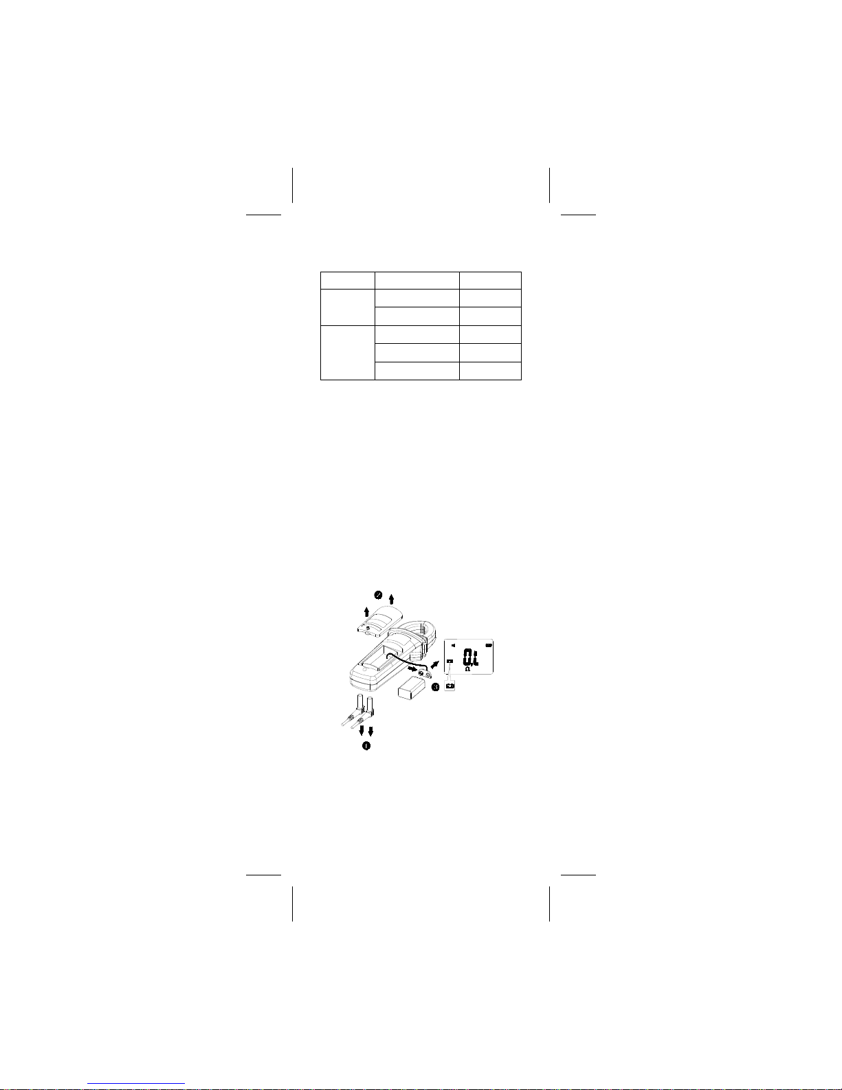
Battery Replacement
When the low battery indicator "<"
appears on the LCD, replace the batteries
with the type given in the specifications.
WARNING
Disconnect the test leads from the circuit
and the instrument before removing the
battery cover.
Refer to the following figure to replace the
batteries :

EN - 16
Limited Warranty
This instrument is warranted to the original
purchaser against defects in material and
workmanship for 3 year from the date of
purchase. During this warranty period, RS
Components will, at its option, replace or
repair the defective unit, subject to verification of the defect or malfunction.
This warranty does not cover disposable
batteries, or damage from abuse, neglect,
accident, unauthorized repair, alteration,
contamination, or abnormal conditions of
operation or handling.
Any implied warranties arising out of the
sale of this product, including but not limited to implied warranties of merchantability
and fitness for a particular purpose, are
limited to the above. RS Components shall
not be liable for loss of use of the instrument or other incidental or consequential
damages, expenses, or economic loss, or
for any claim or claims for such damage,
expense or economic loss. Some states or
countries laws vary, so the above limitations or exclusions may not apply to you.
For full terms and conditions, refer to the
current RS Catalogue.

EN - 17

EN - 18
Africa
RS Components SA
P.O. Box 12182,
Vorna Valley, 1686
20 Indianapolis Street,
Kyalami Business Park,
Kyalami, Midrand
South Africa
www.rs-components.com
Asia
RS Components Pte Ltd.
31 Tech Park Crescent
Singapore 638040
www.rs-components.com
China
RS Components Ltd.
Suite 23 A-C
East Sea Business Centre
Phase 2
No. 618 Yan'an Eastern Road
Shanghai, 200001
China
www.rs-components.com
Europe
RS Components Ltd.
PO Box 99, Corby,
Northants. NN17 9RS
United Kingdom
www.rs-components.com
Japan
RS Components Ltd.
West Tower (12th Floor),
Yokohama Business Park,
134 Godocho, Hodogaya,
Yokohama, Kanagawa 240-0005
Japan
www.rs-components.com
U.S.A
Allied Electronics
7151 Jack Newell Blvd. S.
Fort Worth, Texas 76118
U.S.A.
www.alliedelec.com
South America
RS Componentes Limitada
Av. Pdte. Eduardo Frei M. 6001-71
Centro Empresas El Cortijo
Conchali, Santiago, Chile
www.rs-components.com
 Loading...