

Page 1
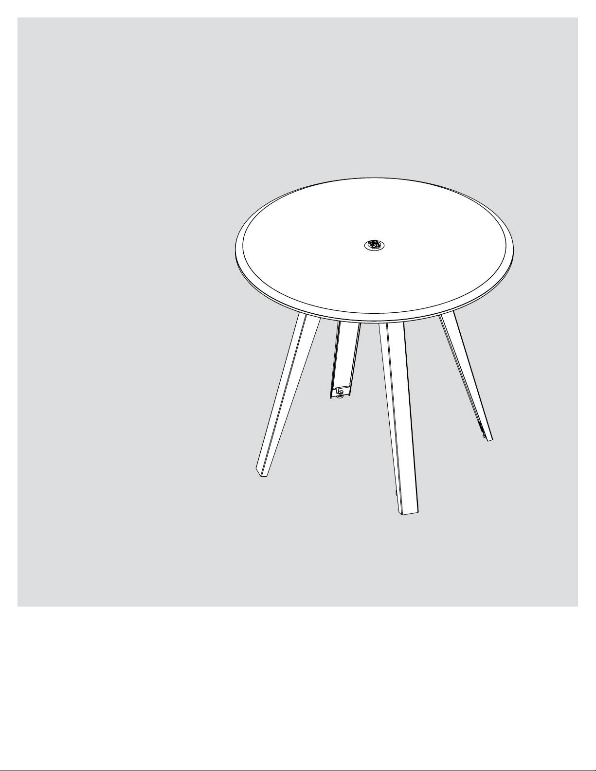
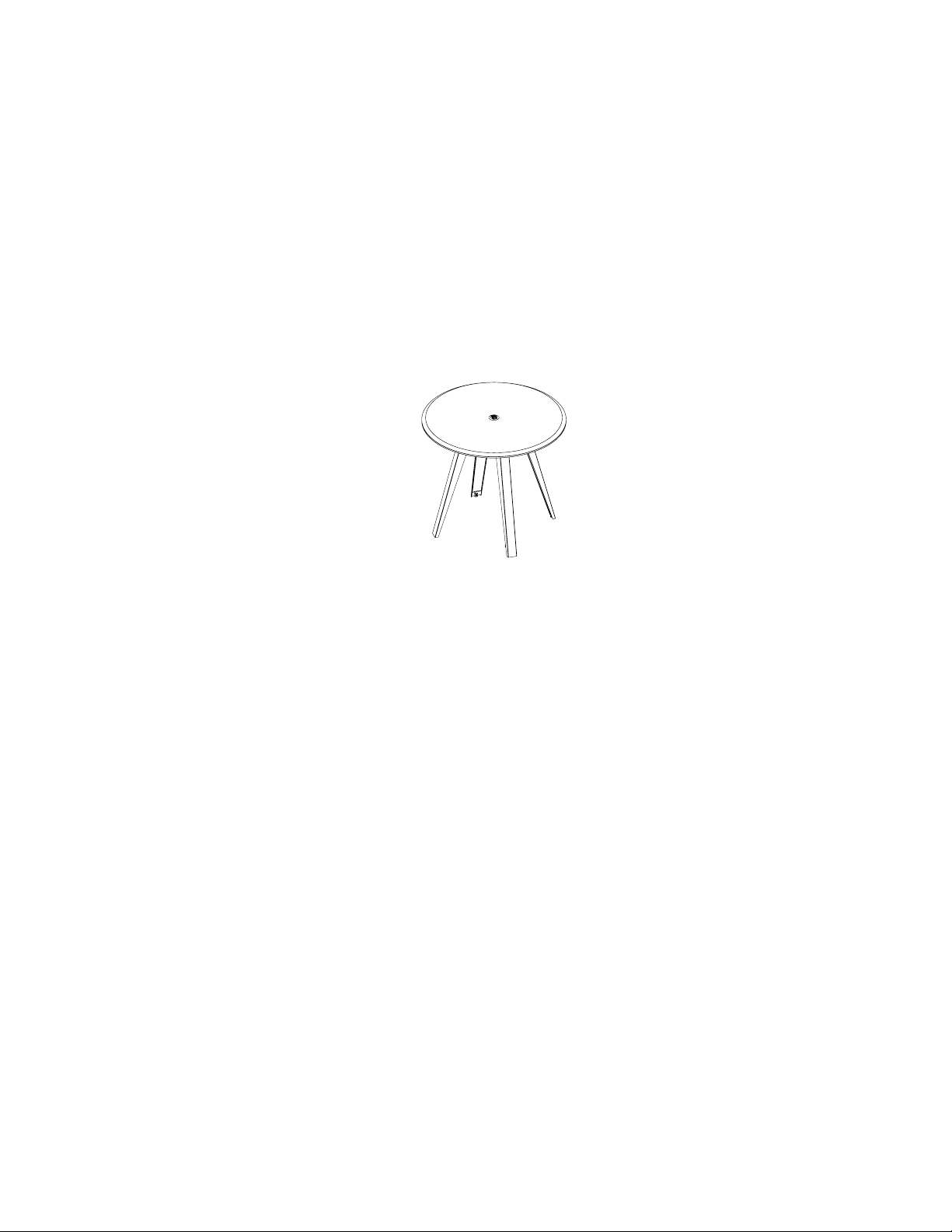
SLANT
TABLE LEG
USER GUIDE
Page 2

TABLE OF CONTENTS
Parts Diagram 4
42", 36", 29" Legs 4
Safety Information 5
Assembly Instructions 6-7
STANDARDS & CERTIFICATIONS
Meets 2014 BIFMA standards.
WARRANTY
Contact your sales representative for warranty information.
OV1010 | 3
Page 3
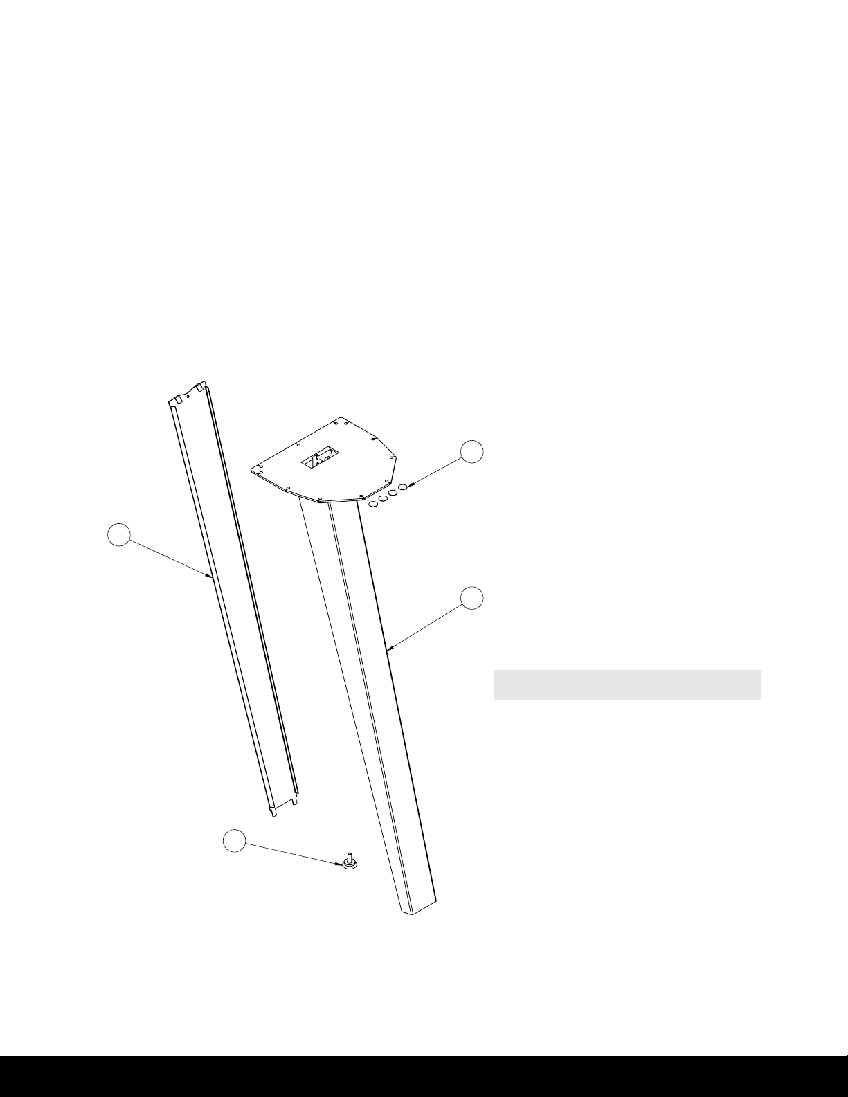
PARTS DIAGRAM
2
4
1
4 |
PARTS Qty/Package
1. Leg 1
2. Cover Panel 1
3. Glide Foot 1
4. Felt Pads 4
3
Page 4

SAFETY INFORMATION
SAFETY
INFORMATION
IMPORTANT SAFETY INSTRUCTIONS Save these instructions.
INSTALL ONLY APPROVED WORK SURFACES
This table system does not include a work surface (desktop). Desktop dimensions for four-leg congurations
are not to exceed 60" diameter. If you are unsure if your preferred work surface meets specications, contact
customer service.
DO NOT OVERLOAD DESK
To prevent table from tipping or collapsing, make sure the desk frame is not overloaded by the weight
of tabletop and objects on table. Evenly distribute load; excess loads near edges can reduce stability
and cause table to tip over.
• Do not exceed maximum load (including weight of desktop) of 200 lb (91Kg)
• Do not sit or stand on table
USE CARE WHEN MOVING TABLE
• Remove all objects and mounted accessories from the table before moving
• Clear objects and equipment from table before rolling to reduce the risk of tipping over
| 5
Page 5
ASSEMBLY INSTRUCTIONS
ASSEMBLY
INSTRUCTIONS
The assembly of the table frame to be made in accordance with this manual.
Changes to the table frame or improper use may affect the safety, function, and life of your product.
This manual applies to the following table legs: 29", 36" and 42".
ILLUSTRATION A
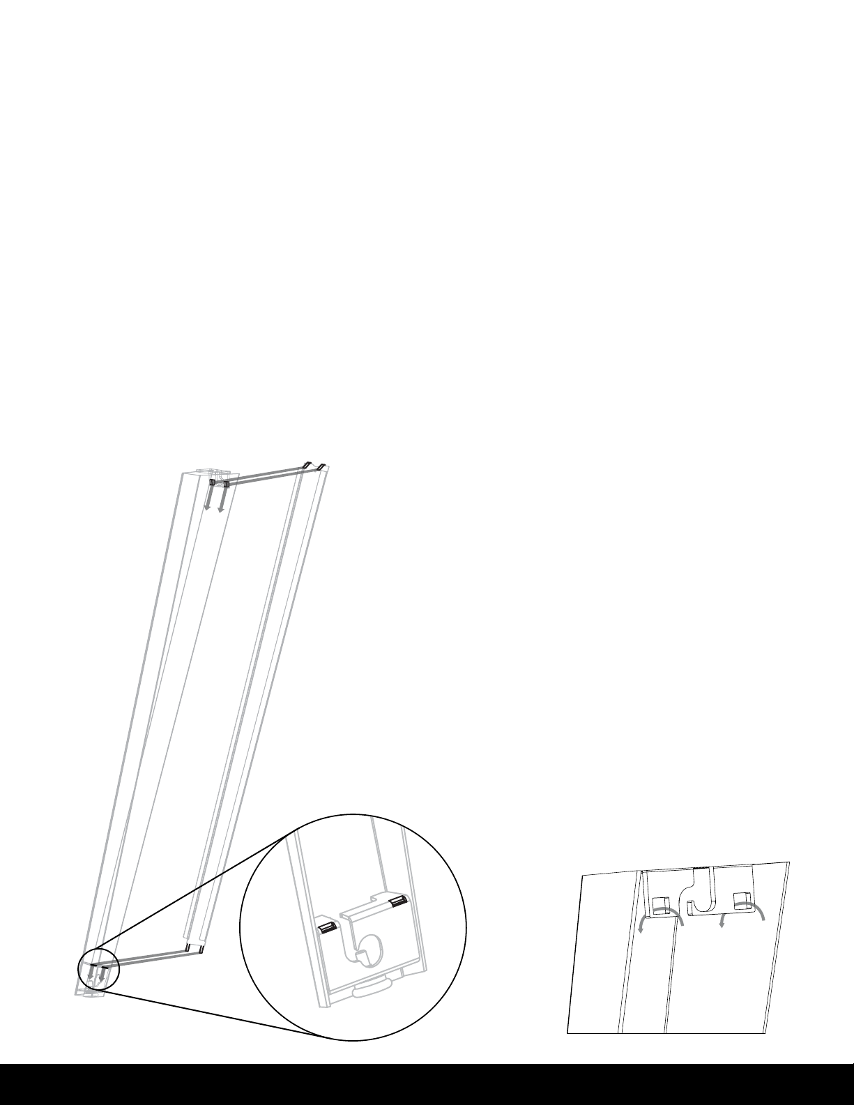
INSTALL LEG ASSEMBLY TO THE TABLE TOP
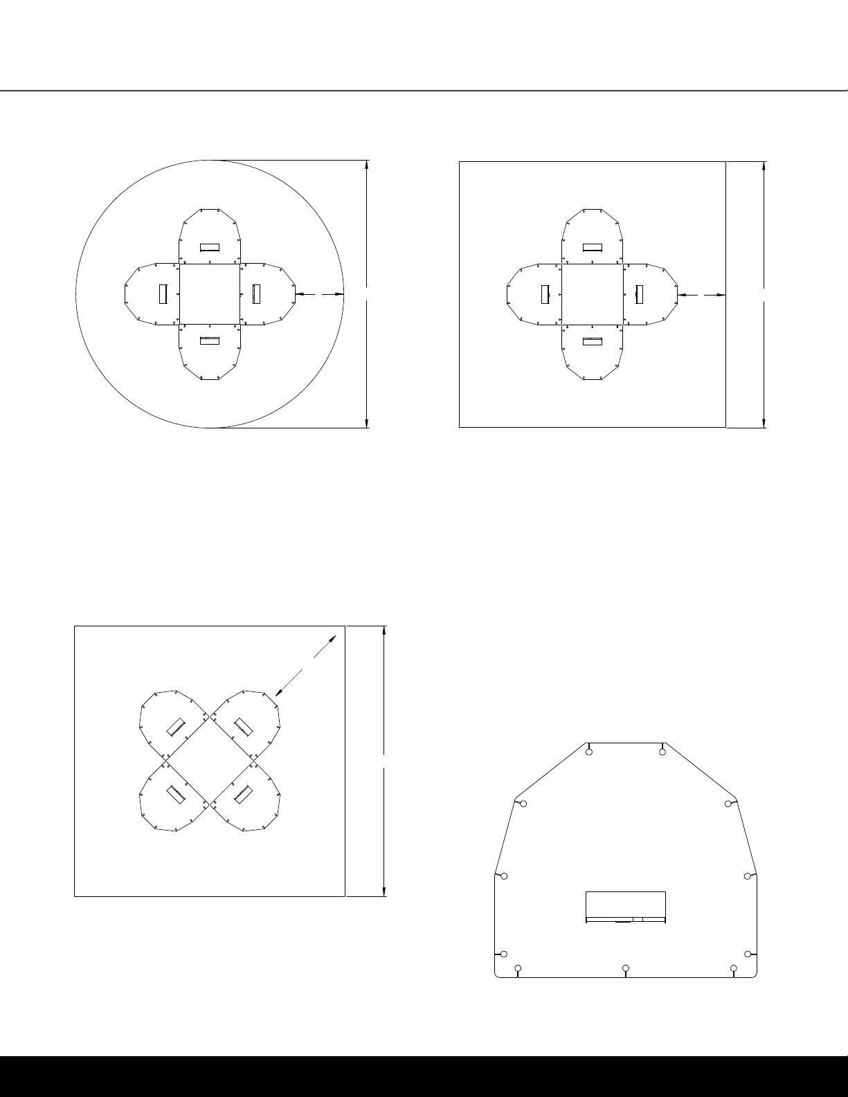
See Illustrations C–E to choose your preferred conguration.
1
Mark the locations of the pilot holes. Drill the pilot holes
to the size recommended by the table top manufacturer.
Install the screws through the mounting plate into the table
top. NOTE: The holes in the mounting plate are .13 in
FEED CORD THROUGH LEG
Route the cord into top and bottom hooks. Gather as much
2
length as desired in the space between the two hooks.
ATTACH FELT PADS TO TABS
Felt pads will eliminate any rattle that may occur where
3
cover is attached to leg. At top of leg, place pads into slots
and fold down to overlap.
around each of the lower tabs on the cover.
INSTALL COVER PANEL TO LEG
Insert tabs on top of cover panel into corresponding slots of
4
leg. Slide cover panel downward so that bottom tabs insert
into corresponding slots at the bottom of the foot.
See Illustration A
See Illustration B.
Wrap pads
6 |
ILLUSTRATION B
Page 6
ASSEMBLY INSTRUCTIONS
ILLUSTRATION C
X
Y
ILLUSTRATION D
X
ROUND TOP CENTER CONFIGURATION SQUARE TOP CENTER CONFIGURATION
42"
X: 8.75"
Y: 48" (minimum
table top size)
36"
X: 6.8125"
Y: 46" (minimum
table top size)
29"
X: 4.75"
Y: 40" (minimum
table top size)
42"
X: 8.75"
Y: 48" (minimum
table top size)
36"
X: 6.8125"
Y: 46" (minimum
table top size)
29"
X: 4.75"
Y: 40" (minimum
table top size)
Y
ILLUSTRATION E
X
SQUARE TOP CORNER CONFIGURATION
42"
X: 11.5"
Y: 38" minimum
table top size
36"
X: 9.5"
Y: 36" minimum
table top size
29"
X: 7.375"
Y: 32" minimum
table top size
Maximum tabletop diameter is 60".
If you have any difculty assembling this unit, or need to
order replacement parts, please contact our Customer
Service department. Use the parts diagram on page 4
as a reference.
Y
MOUNTING PLATE
| 7
Page 7
SLANT
USER GUIDE
 Loading...