

PIVOT
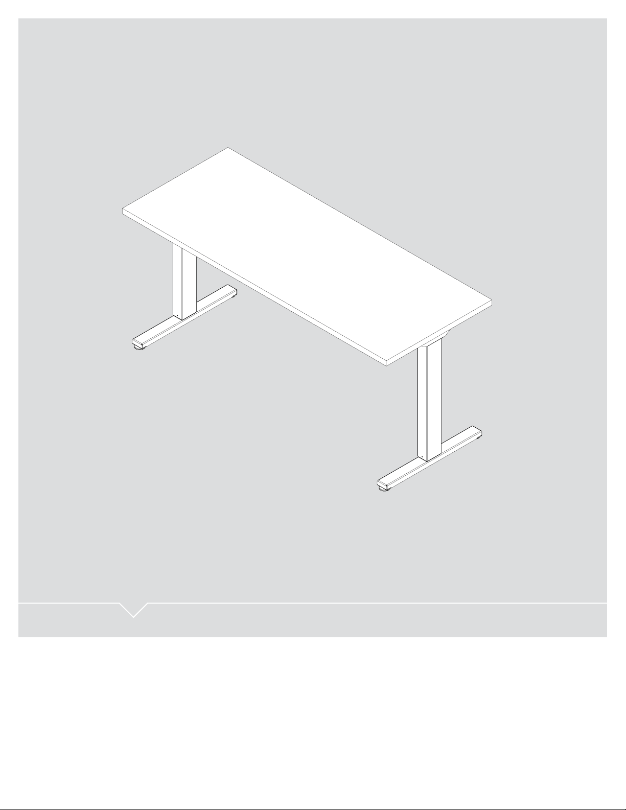
HEIGHT ADJUSTABLE TABLE
USER GUIDE

PIVOT
HEIGHT ADJUSTABLE TABLE
FEATURES
• Full table base (add your own work surface)
• Meets BIFMA X5.5 standards
• UL 962 approved
• Easy-order with one part number
• Lift capacity up to 250 lb.
2 |

TABLE OF CONTENTS
Parts Diagram 4-5
Independent Table 4
Table with Anti-Sag Bar 5
Safety Information 6-7
TABLE OF CONTENTS
Assembly Instructions 8-11
Operation 12
Initialization and Reset 12
Handswitch Operation 12
Troubleshooting 13
Unit Errors 13
Technical Data 14
Warranty 15
Standards & Certications 15
This manual explains how this sit-stand desk is assembled, used, and maintained.
All sit-stand tables are subjected to functional and quality tests before leaving
our facility.
| 3

PIVOT
PARTS DIAGRAM
INDEPENDENT TABLE
For tables up to 60"
2 34
5
1
4 |
PARTS Qty/Package
1. Column 2
2. Handswitch 1
3. Control Box 1
4. Power Cord 1
5. #10 x ¾" Screw 24

TABLE WITH ANTI-SAG BAR
For tables over 60"
5
6
1
2 34
PARTS Qty/Package
1. Column 2
2. Handswitch 1
3. Control Box 1
4. Power Cord 1
5. Anti-Sag Bar 1
6. #10 x ¾" Screw 42
| 5

1"
1"
1"
1"
1"
1"
SAFETY
INFORMATION
IMPORTANT SAFETY INSTRUCTIONS Save these instructions.
DANGER
Always unplug this furnishing from the electrical outlet before cleaning.
WARNING:
follow this safety information and the provided instructions when assembling this product.
Do not change or replace components and accessories.
To reduce the risk of electric shock:
To reduce the risk of death, serious injury, or property damage, read and
INSTALL ONLY APPROVED WORK SURFACES
This table system does not include a work surface (desktop). Work surface must be at least ¾" thick and weigh no
more than 5 lb. per square foot (For example, a 2'x6' desktop should weigh no more than 60 lb). Do not exceed a
maximum weight for the desktop of 75 lb. To prevent table from tipping or collapsing, make sure the desk frame
is not overloaded by the weight of tabletop and objects you plan to put on the table. If you are unsure, contact
customer service.
KEEP AWAY FROM CHILDREN
This table system is not designed for use in homes or other areas accessible by small children.
For indoor commercial ofce use only.
BE CAREFUL WHEN ADJUSTING DESK HEIGHT
6 |
Body parts and property can be caught between the
moving work surface and an immobile obstacle (such as
shelves, furniture, window sills, or walls). Keep at least
one inch of clearance around desk and make sure nothing
is in table’s path for its entire range of motion.
Before raising or lowering:
• Check surroundings on all sides of desk are clear
• Make sure corded objects will not be pulled off table
or cause other objects to fall
• Make sure desk power cord moves freely
as desk moves up and down

SAFETY INFORMATION
DO NOT OVERLOAD DESK
To prevent table from tipping or collapsing, make sure the desk frame is not overloaded by the weight
of tabletop and objects on table. Evenly distribute load; excess loads near edges can reduce stability
and lead to tip over.
• Do not exceed maximum load (including weight of desktop) of 250 lb. (113Kg)
• Do not exceed edge load of 25 lb. when positioning monitors or mounting accessories.
• Do not sit or stand on table
USE CARE WHEN MOVING DESK
• Clear objects and equipment from table before moving to reduce the risk of tipping over.
• Adjust the desk to its lowest height before moving
• To disconnect, remove plug from outlet
• Do not move a loaded desk
DO NOT OPEN ELECTRICAL COMPONENTS
Do not attempt to service table components. There are no user-serviceable parts inside the motor control
units or table legs. If your table needs service, contact customer service. Never operate this table if
it has a damaged cord or plug, if it is not working properly, or if it has been dropped or damaged.
KEEP TABLE FRAME DRY
Keep all electrical components away from water and high humidity. Clean only with a dry or
slightly damp cloth. Do not spray cleaning solutions directly onto table system.
GROUNDING INSTRUCTIONS
This product is equipped with a cord having an
equipment-grounding conductor and a grounding plug.
Use only the cord provided. Make sure that the product
is connected to an outlet having the same conguration
as the plug (as shown in Illustration A) that is properly
installed and grounded in accordance with all local
codes and ordinances.
Do not modify the plug provided with the product
– if it will not t the outlet, have a proper outlet
installed by a qualied electrician.
ILLUSTRATION A
Grounding
Pin
No adapters are to be used with this product.
Keep cord away from heated surfaces.
Grounded
Outlet
Grounded Outlet Box
| 7

ASSEMBLY
INSTRUCTIONS
The assembly of the table frame to be made in accordance with this manual.
Changes to the table frame or improper use may affect the safety, function, and life of your product.
ASSEMBLY OVERVIEW
1. Assemble the columns to the top
2. Fasten the control box and handswitch to the table top
3. Connect the motor cables to the control box
4. Connect the handswitch (HS) cable to the control box
5. Connect the supplied power cord (AC) to the control box
6. Attach all cables to the table frame or on the underside
of the table top
If you have any difculty assembling this unit, or need to order
replacement parts, please contact our Customer Service department.
Use the parts diagrams on page 4-5 as a reference.
8 |

1
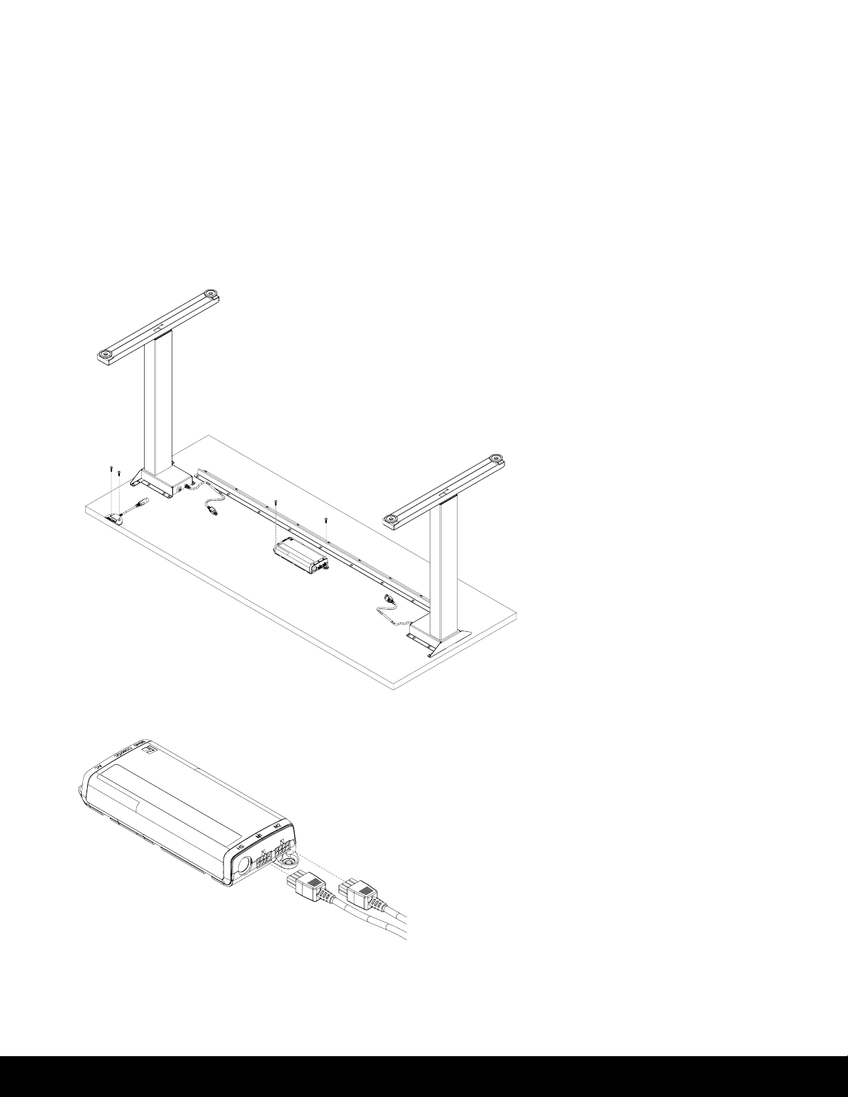
ASSEMBLY INSTRUCTIONS
ASSEMBLE THE COLUMNS TO THE WORK SURFACE
Center the columns front to back on the work surface.
Use the #10 x ¾" screws to fasten the top support onto the
table top. Be sure motor boxes are mounted 1.5" from edge
of work surface.
1B
1.5 in
FOR TABLES OVER 60" ONLY
ASSEMBLE THE ANTI-SAG BAR TO THE WORK SURFACE
Tables under 60" do not require anti-sag bar.
| 9
ASSEMBLY INSTRUCTIONS
2
FASTEN THE CONTROL BOX AND
HANDSWITCH TO THE TABLE TOP
Make sure the control box and handswitch are fastened
in a location where all the cables will connect without
being in tension. Be sure to use approved screws per the
table top supplier.
10 |
CONNECT THE MOTOR CABLES
TO THE CONTROL BOX
3
The motor cable plug-connection has to
click into place.
Connections to the control box:
M1-M2 = Connectors for the columns
HS = Connectors for the handset
AC = Connector for the power cord (3-pin)

CONNECT THE HANDSWITCH (HS) CABLE
TO THE CONTROL BOX
4
ASSEMBLY INSTRUCTIONS
CONNECT THE SUPPLIED POWER CORD (AC)
TO THE CONTROL BOX
5
ATTACH ALL CABLES TO THE TABLE FRAME
OR ON THE UNDERSIDE OF THE TABLE TOP
6
Attach cables in order to avoid any damage during operation.
Never wrap cables and/or cords around the columns.
| 11

OPERATION
INFORMATION
INITIALIZATION/RESET
The desk must be initialized/reset after any of the following:
- After assembly
- After disconnection from the power supply
- After any impact on the table top.
To initialize/reset, move the table to the lowest position by pressing the DOWN button on the handswitch
until the columns reach the lowest position. Press the DOWN button again until the table moves slightly
back up to the operation zero point. Release the DOWN button. If the button is released too soon, the table
legs will not move up. Repeat the reset process.
The control box is programmed with a parameter le which controls the table legs' lower and upper travel
limits. Under no circumstance should a control box from one table be moved to another.
NORMAL HANDSWITCH OPERATION (for all handswitch types)
By pressing the UP or DOWN buttons, the table will move up or down to the desired position. Once the
desired position is reached, let go of the UP or DOWN button. The table legs will stop once they reach
the lower or upper height limits.
12 |

TROUBLESHOOTING
UNIT
TROUBLESHOOTI
ERROR CODE
Table does not
move
SOURCE SOLUTION
No power supply Plug in the power cord or check the connection
on the control box
No connection or a loose
connection to the drives
No connection or a loose
connection to the handswitch
Max lifting capacity
is exceeded
Max time limit is exceeded Control is activated automatically after approx. 9 minutes
Defective drive Contact customer service
Defective control box Contact customer service
Defective handswitch
Verify the plug connections of the motor cable
to the control box
Verify the plug connections of the motor cable
to the control box
Reduce the weight or load on the desktop
Replace the handswitch
Table moves
down at a
slow rate
During operation,
tables moves at
a slow rate
Table moves
on one side only
briefly and then
stops
Control box expects
new reset
Max lifting capacity
is exceeded
No connection or a loose
connection to the drives
Defective drive
Reset control box. (See page 12)
Reduce weight
Verify the plug connections of the motor cable
to the control box and reset the control box
Contact customer service
| 13

TROUBLESHOOTING
TECHNICAL DATA
GENERAL CONTROL BOX
Power supply
Standby power consumption, primarily
Operating temperature
Protection class
Maximum power output
TWO-COLUMN FRAME WITH CONTROL BOX
Maximum lift capacity
Adj. range, depending on version
Maximum input current
Maximum duty cycle
ILLUSTRATION B
SINGLE STAGE
120 VAC ±10% / 60 Hz
<0.3 W
0-35°C
IP 20
240VA/24V
250 lb (≈ 113 kg / 1112N)
View Illustration B
5 A
30 sec. on / 9 min. off
14 |
stroke
length
19"

TROUBLESHOOTING
ST
The drive system is tested according to the following standards:
UL 962
Issued: 2019/05/21 Ed: 4 Household and Commercial Furnishings
CSA C22.2#68
Issued: 2019/05/21 Ed: 8 (R2018)
Motor-Operated Appliances (Household and Commercial)
Meets BIFMA x5.5 2014.
ANDARDS & CERTIFICATIONS
WARRANTY
CONTACT YOUR SALES REPRESENTATIVE FOR WARRANTY INFORMATION
End of life cycle: Once product is disassembled, all steel components can be recycled at your local metal collector.
| 15

PIVOT
USER GUIDE
 Loading...