


 Loading...
Split-Pak™ Condensing Unit and
Refrigeration System
Installation & Operations Manual
R448A/R449A, R407 & R404A
Images are for illustration only and may not reflect your exact model.
57-02611/101628
REV. 06-02-21
6/21 57-02611 / 101628 ©2021, Refrigerated Solutions Group™. All rights reserved. |
1 |

TABLE OF CONTENTS
INTRODUCTION...................................................................................................................................... |
3 |
WARNING LABELS AND SAFETY INSTRUCTIONS....................................................................... |
4 |
M-SERIES CONDENSING UNIT FEATURES..................................................................................... |
5 |
REFRIGERATION MODEL NOMENCLATURE ............................................................................... |
6 |
PRE-INSTALLATION INSTRUCTIONS .............................................................................................. |
7 |
General Information............................................................................................................................... |
7 |
Delivery Inspection................................................................................................................................ |
7 |
INSTALLATION INSTRUCTIONS ...................................................................................................... |
7 |
Handling and Placement of Condensing Unit........................................................................................ |
7 |
Handling and Placement of Evaporator Coil in Walk-In....................................................................... |
8 |
Electrical ................................................................................................................................................ |
9 |
Refrigerant Piping.................................................................................................................................. |
9 |
Leak Check .......................................................................................................................................... |
10 |
Evacuation, Dehydration and Start-Up ................................................................................................ |
10 |
Evacuation Procedure .......................................................................................................................... |
10 |
Finish Charging Procedures................................................................................................................. |
11 |
Preliminary........................................................................................................................................... |
11 |
Remote M-Series ................................................................................................................................. |
11 |
Pre-Charged Remote Refrigeration Systems ................................................................................. |
12-13 |
Final Check List for All Models .......................................................................................................... |
14 |
SUCTION AND LIQUID LINE SIZES........................................................................................... |
15-22 |
EQUIVALENT LENGTH ALLOWANCE FOR FITTINGS ............................................................. |
23 |
GENERAL INFORMATION................................................................................................................. |
23 |
LOW AMBIENT CHARGE CHART.................................................................................................... |
24 |
SYSTEM TROUBLESHOOTING CHART ......................................................................................... |
25 |
UNIT BASE SPECIFICATIONS ..................................................................................................... |
26-27 |
SALE AND DISPOSAL .......................................................................................................................... |
28 |
INSTALLATION DATA SHEET .......................................................................................................... |
29 |
6/21 57-02611 / 101628 ©2021, Refrigerated Solutions Group™. All rights reserved. |
2 |

INTRODUCTION
This manual contains important instructions for installation, use and service. Read all of this manual carefully before installing or servicing your refrigeration equipment.
 NOTICE Installation and service of the refrigeration and electrical components must be performed by a refrigeration mechanic or licensed electrician.
The portions of this manual covering refrigeration and electrical components contain technical instructions intended only for persons qualified to perform refrigeration and electrical work.
 DANGER
Equipment MUST be properly grounded.
Improper or faulty hook-up of electrical components of the refrigeration units can result in severe injury or death.
All electrical wiring hook-ups must be done in accordance with all applicable local, regional or national standards.
 NOTICE
Read this manual before installing your refrigeration. Keep the manual and refer to it before doing any service. Failure to do so could result in personal injury or equipment damage.
This manual cannot cover every installation, use or service situation. If you need additional information, contact us at:
Parts and Technical Service Department
800-388-5253
6/21 57-02611 / 101628 ©2021, Refrigerated Solutions Group™. All rights reserved. |
3 |
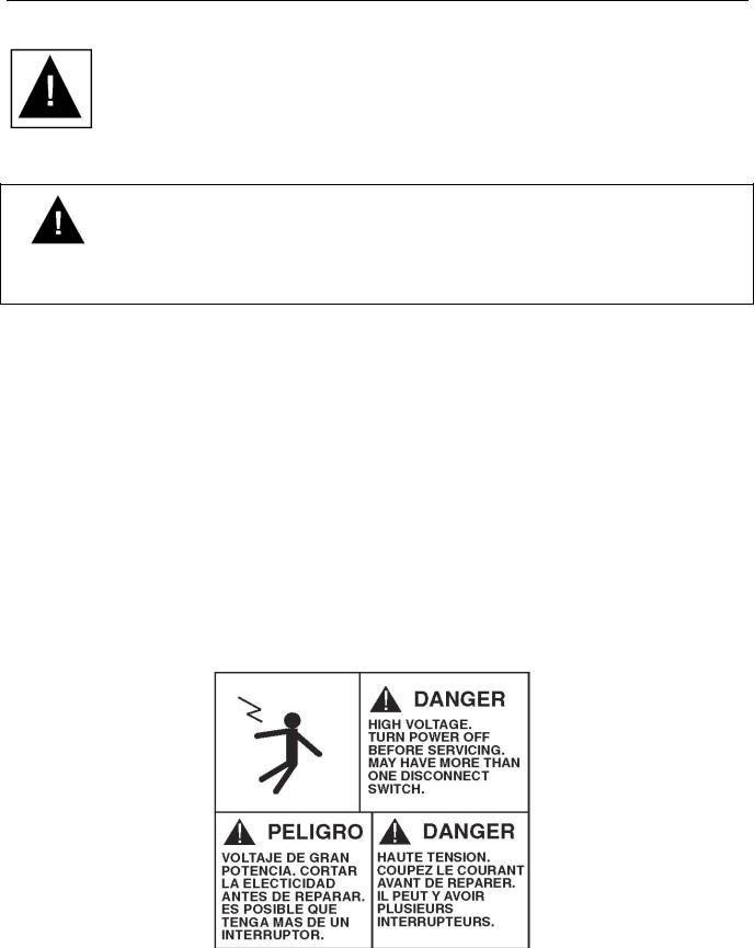
WARNING LABELS AND SAFETY INSTRUCTIONS
This is the safety-alert symbol. When you see this symbol, be alert to the potential for personal injury or damage to your equipment.
Be sure you understand all safety messages and always follow recommended precautions and safe operating practices.
NOTICE TO EMPLOYERS
You must make sure that everyone who installs uses or services your refrigeration is thoroughly familiar with all safety information and procedures.
Important safety information is presented in this section and throughout the manual. The following signal words are used in the warnings and safety messages.
DANGER: Severe injury or death WILL occur if you ignore the message.
WARNING: Severe injury or death CAN occur if you ignore the message.
CAUTION: Minor injury or damage to your refrigeration can occur if you ignore the message.
NOTICE: This is important installation, operation, or service information. If you ignore the message, you may damage your refrigeration.
The warning and safety labels shown throughout this manual are placed on your refrigeration at the factory. Follow all warning label instructions. If any warning or safety labels become lost or damaged, call our parts and technical service department for replacements.
This label is located on the condensing unit.
6/21 57-02611 / 101628 ©2021, Refrigerated Solutions Group™. All rights reserved. |
4 |

M-SERIES CONDENSING UNIT FEATURES
STANDARD COMPONENTS
The M-Series set of standard features (pre-wired and mounted except as noted) * include:
●Preset non-adjustable high-pressure control and preset non-adjustable low-pressure control**
●Crankcase heater
●Head pressure control (flooding valve)
●Heavy gauge, galvanized steel mechanically fastened weather hood
●Suction service valve
●Heavy-duty angle leg base
●Liquid line filter/drier
●Pre-wired electrical control panel
●Sight glass
●Liquid and suction line kit with service valve
●Timer (standard on low temp and medium temp units)
●Compressor contactor
●Defrost heater contactor (when required)
●Generously sized condenser (rated up to 120° ambient)
●Rifled tubes in condenser for greater efficiency
●Liquid line shut-off valve for easy change of filter
●PSC condenser fan motors
●Large liquid receiver (good for maximum 100 ft. line run)
●One-year limited compressor warranty
●Low Pressure Control settings: cut out at 3psig and cut in at 20psig
●High Pressure Control settings: cut out is 450 psig and cut in at 375 psig
*Components may vary depending on horsepower and application. Consult our factory for verification of standard and optional components.
**Preset high pressure control and preset low pressure control are non-adjustable in medium temp M-Series units. The low-pressure control is adjustable in low temp units.
OPTIONALLY AVAILABLE
●Special voltages
●Insulated and heated receiver (thermostatically controlled)
●Suction accumulator
●Coated condenser coils
●Oil separator
●Phase loss/low voltage monitor
●Factory pre-assembled evaporator coil (includes factory pre-mounting of thermostatic air control and expansion valve)
●Factory pre-charged system with quick connect liquid and suction line sets up to 50 ft. (specify length when ordering)
●Adjustable low-pressure control for medium and high temp units
●Dual pressure control
●Circuit breaker
●Suction filter
●Fan cycling switch
●Pre-mounted solenoid at evaporator
●Liquid line solenoid valve (shipped loose)
●Extended four years limited compressor warranty
●Master Controller OEM 4.0 electronic control system
●Reverse cycle defrost
6/21 57-02611 / 101628 ©2021, Refrigerated Solutions Group™. All rights reserved. |
5 |
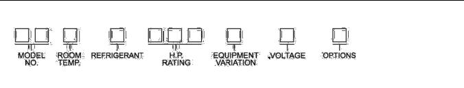
REFRIGERATION MODEL NOMENCLATURE
MODEL NUMBER EXPLANATION
MH = Hermetic Condensing Unit
MS = Scroll Condensing Unit
ROOM TEMPERATURE EXPLANATION
L = 0° F. Thru -30° F. Room Temperature
M = 0° Thru +55° F. Room Temperature
REFRIGERANT EXPLANATION
D = R448A/R449A
V = R-407A
Z = R-404A (available where applicable codes allow)
HORSEPOWER RATING EXPLANATION
005 |
= ½ H.P. |
017 |
= 1¾ H.P. |
040 |
= 4H.P. |
100 = 10 H.P. |
||
007 |
= ¾ H.P. |
020 = 2 H.P. |
045 |
= 4 |
1/2H.P. |
130 = 13 H.P. |
||
010 |
= 1 |
H.P. |
025 |
= 2½ H.P. |
050 = 5 H.P. |
150 = 15 H.P. |
||
012 |
= 1 |
1/4 H.P. |
030 = 3 H.P. |
060 |
= 6 |
H.P. |
|
|
015 |
= 1 |
1/2 H.P. |
035 |
= 3 1/2 H.P. |
075 = 7 1/2 H.P. |
|
||
EQUIPMENT VARIATION EXPLANATION
A = STANDARD UNIT
H = HEATED AND INSULATED RECEIVER
E = ELECTRIC DEFROST
M = FLOATING HEAD (MC)
R= REVERSING VALVE
VOLTAGE EXPLANATION
A = 115/60/1 |
F = 200-220/50/3 |
B = 230/60/1 or 208-230/60/1 (As Applicable) |
G = 380-420/50/3 |
C = 208-230/60/3 |
J = 380/50/1 |
D = 460/60/1 |
K = 200-220/50/1 or 220/50/1 |
E = 460/60/3 |
|
6/21 57-02611 / 101628 ©2021, Refrigerated Solutions Group™. All rights reserved. |
6 |

PRE-INSTALLATION INSTRUCTIONS
I. General Information
Please read this manual prior to installing your equipment. This information is based on good refrigeration practice and should be used as a guide for installation and operation.
To complete the installation, please record the data requested on the Installation Data form on the last page of the manual and return this manual to the owner.
II. Delivery Inspection
You are responsible for filing all freight claims with the delivering truck line. Inspect all cartons and crates for damage as soon as they arrive. If damage is noted to shipping crates, cartons or if a shortage is found; note this on the bill of lading (all copies) prior to signing.
If damage is discovered when the cabinet is uncrated, immediately call the delivering truck line and follow up the call with a written report indicating concealed damage to your shipment. Ask for an immediate inspection of your concealed damage item. Crating material MUST be retained to show the inspector from the truck line.
INSTALLATION INSTRUCTIONS
I. Handling and Placement of Condensing Unit
To minimize damage to the unit housing, it is recommended that the crate not be removed until the unit is moved to its final location.
The following should be considered when placing the unit:
A.The condenser coil (air inlet) should not be located where air flow into the coil would be restricted.
A minimum of 18" is required between the face of the coil and a wall or other vertical obstruction (may vary with different models).
B.A minimum of 6" is required on the sides to allow access to the housing clamps.
C.A minimum of 24" is required on the louvered end (air outlet) for clearance when opening housing and for ease of maintenance.
D.Do not position multiple units so that the air discharge of one is into the condenser air intake of another.
Holes are provided in the base supports for mounting bolts and for bridle lift rods.
For indoor mounting, motor rooms should be provided with fans designed to move 1000 cfm of air per ton of refrigeration.
6/21 57-02611 / 101628 ©2021, Refrigerated Solutions Group™. All rights reserved. |
7 |

II. Handling and Placement of Evaporator Coil in Walk-In
To minimize damage to the evaporator coil, it is recommended that the carton (or crate) not be removed until the evaporator coil is moved close to its final location. When the container is removed from the evaporator coil, extreme care must be used when lifting and mounting to the ceiling, to prevent sheet metal damage.
EVAPORATOR INSTALLATION INSTRUCTIONS
A.Do not install the evaporator too close to door openings to prevent icing problems.
B.Minimum clearance between evaporator and the walls is equal to or greater than the coil height for proper air flow and service access.
C.Refer to the evaporator coil drawing dimension for mounting holes location.
D.Install washers and secure with nuts. Tighten until the coil is firm against the ceiling. The evaporator coil must be level.
EVAPORATOR DRAIN LINE INSTALLATION:
6/21 57-02611 / 101628 ©2021, Refrigerated Solutions Group™. All rights reserved. |
8 |

III. Electrical
Electric power supply must match the condensing unit power requirements indicated on the unit data plate.
A WIRING DIAGRAM IS LOCATED ON THE INSIDE OF THE ELECTRICAL BOX COVER.
All field wiring may enter the holes provided in left side, back and bottom of the electrical box. All field wiring should be done in a professional manner, in accordance with all governing codes. Double check all wiring connections, including factory terminals, before start-up of condensing unit.
 DANGER
Installation of the refrigeration and electrical components must be performed only by a refrigeration mechanic or licensed electrician.
Improper or faulty hook-up of electrical components can result in death.
IV. Refrigerant Piping
The condensing unit must remain sealed and pressurized from the manufacturer until piping is complete and final connections are ready to be made.
Use only refrigeration grade copper tubing, (ACR), type "L", bright annealed, dehydrated, and properly sealed against contamination. Soft temper tubing may not be used for field interconnection of refrigeration components (condensing unit to evaporator assembly). Take extreme care to keep refrigeration tubing clean and dry prior to installation. Use an appropriate size tube cutter (DO NOT CUT TUBING WITH A SAW).
Note: The liquid line size is determined by conventional piping practices for air and electric defrost (use chart on pages 15-1). For reverse cycle defrost, the liquid line must be selected by choosing the liquid line one nominal step larger than the conventional approach.
Suction lines should slope down 1/2 inch for each 10 feet of horizontal run towards the compressor.
If any portion of the suction line rises above the exit elevation of the evaporator, P-type oil traps should be located at the base of each suction riser for proper oil return to the compressor. An additional trap is needed for every 20 feet of rise and an inverted trap should be installed on the roof
When brazing, dry nitrogen MUST be passed through the lines at low pressure to prevent scaling and oxidation inside the tubing and fittings. All flux must be removed from the joints after brazing.
MINIMIZE the amount of flux used to prevent internal contamination of the refrigeration system.
Silver brazing wire is to be utilized (high temperature alloy of 15% silver content on all copper-to-copper connections, and high temperature alloy of 45% silver content on all dissimilar metal connections).
6/21 57-02611 / 101628 ©2021, Refrigerated Solutions Group™. All rights reserved. |
9 |
 NOTICE
Be sure solenoid valves are open before beginning evacuation and leak check.
V. Leak Check
When all refrigeration line connections have been made, the complete system, including factory connections, should be leak checked.
Add the proper refrigerant to 60 PSIG, then boost to 175 PSIG with dry nitrogen. Leak check all joints with an electronic leak detector or a halide torch. If leaks are found, relieve the pressure, and make repairs as necessary and recheck.
VI. Evacuation, Dehydration and Start-Up
A vacuum of 500 microns or less must be pulled to properly dehydrate the system. This requires a two-stage vacuum pump with an electronic vacuum indicator.
***DO NOT USE THE SYSTEM COMPRESSOR AS A VACUUM PUMP. ***
***DO NOT OPERATE COMPRESSOR WHILE SYSTEM IS IN A VACUUM. ***
Evacuation Procedure
A.Open all condensing unit service valves and relieve system pressure. Also, open any line valves installed in the system and energize all solenoid valves to facilitate evacuation.
B.Connect the vacuum pump to the high and low sides of the system using 1/4" or larger cop per lines or 1/4" ID hoses with high vacuum designation.
C.Leaks or moisture will be indicated if the system pressure rises when the vacuum line is closed off.
D.Pull a vacuum of 1500 microns, close vacuum line and “break” vacuum to 3 PSIG, maximum, with refrigerant to be used in the system.
E.Repeat step D.
F.A final vacuum of 250 microns should be pulled before charging. When 250 microns is reached, close vacuum line and charge through high side, with proper refrigerant to the level of 2-1/2 lbs. per ton of refrigeration.
6/21 57-02611 / 101628 ©2021, Refrigerated Solutions Group™. All rights reserved. |
10 |
Loading...