


R&S
®
TSMA6-BP
Battery Pack Unit
Getting Started
Getting Started
Version 03
4900903002
(a0èN2)

This manual describes the following R&S®TSMA6 accessory:
●
R&S®TSMA6-BP Battery Pack Unit (4900.9001.02)
●
R&S MNT®BP89WH Battery for R&S®TSMA6-BP (1321.3772.00)
© 2019 Rohde & Schwarz GmbH & Co. KG
Mühldorfstr. 15, 81671 München, Germany
Phone: +49 89 41 29 - 0
Fax: +49 89 41 29 12 164
Email: info@rohde-schwarz.com
Internet: www.rohde-schwarz.com
Subject to change – Data without tolerance limits is not binding.
R&S® is a registered trademark of Rohde & Schwarz GmbH & Co. KG.
Trade names are trademarks of the owners.
4900.9030.02 | Version 03 | R&S®TSMA6-BP
Throughout this manual, products from Rohde & Schwarz are indicated without the ® symbol , e.g.
R&S®TSMA6 is indicated as R&S TSMA6.

Contents
R&S®TSMA6-BP
3Getting Started 4900.9030.02 ─ 03
Contents
1 Safety Information................................................................. 5
2 Documentation Overview......................................................6
2.1 Getting Started Manual.........................................................................6
2.2 Basic Safety Instructions..................................................................... 6
2.3 Data Sheets and Brochures................................................................. 6
3 Key Features.......................................................................... 7
4 Preparing for Use...................................................................8
4.1 Unpacking and Setting Up the Instrument......................................... 8
4.2 Inserting a Battery in the R&S TSMA6-BP........................................10
4.3 Connecting the R&S TSMA6-BP with External Power Supply........11
4.4 Connecting the R&S TSMA6-BP with R&S TSMA6..........................12
4.5 Connecting the R&S TSMA6-BP with R&S TSME6.......................... 14
5 Operation..............................................................................17
5.1 Operation Modes.................................................................................17
5.2 LED Display......................................................................................... 17
5.3 Monitoring Battery Charge State.......................................................18
5.4 Battery Exchange - Hot Swapping.................................................... 19
Index..................................................................................... 22

Contents
R&S®TSMA6-BP
4Getting Started 4900.9030.02 ─ 03

Safety Information
R&S®TSMA6-BP
5Getting Started 4900.9030.02 ─ 03
1 Safety Information
The product documentation helps you to use the R&S TSMA6-BP safely and efficiently. Follow the instructions provided here and in the printed "Basic Safety
Instructions". Keep the product documentation nearby and offer it to other users.
Intended use
The R&S TSMA6-BP is designated for the development, production and verification of electronic components and devices in industrial, administrative, and laboratory environments. Use the R&S TSMA6-BP only for its designated purpose.
Observe the operating conditions and performance limits stated in the data sheet.
Where do I find safety information?
Safety information is part of the product documentation. It warns you about the
potential dangers and gives instructions how to prevent personal injuries or damage caused by dangerous situations. Safety information is provided as follows:
●
The printed "Basic Safety Instructions" provide safety information in many languages and are delivered with the R&S TSMA6-BP.
●
Throughout the documentation, safety instructions are provided when you
need to take care during setup or operation.

Documentation Overview
R&S®TSMA6-BP
6Getting Started 4900.9030.02 ─ 03
2 Documentation Overview
This section provides an overview of the R&S TSMA6-BP user documentation.
Unless specified otherwise, you find the documents on the R&S TSMA6-BP product page at:
www.rohde-schwarz.com/manual/tsmx
2.1 Getting Started Manual
Introduces the R&S TSMA6-BP and describes how to set up and start working
with the product. Includes basic operations, typical measurement examples, and
general information, e.g. safety instructions, etc. A printed version is delivered
with the instrument.
2.2 Basic Safety Instructions
Contains safety instructions, operating conditions and further important information. The printed document is delivered with the instrument.
2.3 Data Sheets and Brochures
The data sheet contains the technical specifications of the R&S TSMA6-BP. It
also lists optional accessories.
The brochure provides an overview of the instrument and deals with the specific
characteristics.
See www.rohde-schwarz.com/brochure-datasheet/tsmx
Data Sheets and Brochures

Key Features
R&S®TSMA6-BP
7Getting Started 4900.9030.02 ─ 03
3 Key Features
The R&S TSMA6-BP allows to enhance the R&S TSMA6 instrument to a portable
measurement solution based on a battery powered system.
Key Features
●
Power Supply for R&S TSMA6 in portable applications
●
Power Supply for up to 4 R&S TSME6 devices
●
Hot-swap support for endless portable mode
●
In-bay charging feature with smart battery controller
●
Charging display via LED and monitoring window
●
SMBus interface with connected R&S TSMA6
Preparing for Use
R&S®TSMA6-BP
8Getting Started 4900.9030.02 ─ 03
4 Preparing for Use
Risk of injury and instrument damage
The instrument must be used in an appropriate manner to prevent electric
shock, fire, personal injury, or damage.
●
Do not open the instrument casing.
●
Read and observe the "Basic Safety Instructions" delivered as a printed
brochure with the instrument.
In addition, read and observe the safety instructions in the following sections. Notice that the data sheet may specify additional operating conditions.
Risk of instrument damage during operation
An unsuitable operating site or test setup can cause damage to the instrument and to connected devices. Ensure the following operating conditions
before you switch on the instrument:
●
The instrument is dry and shows no sign of condensation.
●
The instrument is positioned as described in the following sections.
●
Signal levels at the input connectors are all within the specified ranges.
4.1 Unpacking and Setting Up the Instrument
The following section describes how to setup the instrument.
Unpacking and Setting Up the Instrument

Preparing for Use
R&S®TSMA6-BP
9Getting Started 4900.9030.02 ─ 03
Risk of instrument damage due to inappropriate operating conditions
Specific operating conditions are required to ensure accurate measurements and to avoid damage to the instrument. Observe the information on
appropriate operating conditions provided in the basic safety instructions
and the instrument's data sheet.
Check the equipment for completeness using the delivery note and the accessory
lists for the various items. Check the instrument for any damage. If there is damage, immediately contact the carrier who delivered the instrument. Make sure not
to discard the box and packing material.
Packing material
Retain the original packing material. If the instrument needs to be transported or shipped later, you can use the material to protect the control elements and connectors.
Accessory list
The following items are included with shipment of the R&S TSMA6-BP:
●
12 V DC IN power supply cable with a cigarette lighter adapter
●
4 x collar screw M2.5 (screwed to the upper side of the R&S TSMA6-BP)
●
Getting Started Manual (Printed)
●
Safety instruction booklet
The following items are optional and must be ordered separately:
●
Charger for batteries (R&S TSMA-BC4, R&S No. 3630.7708.02)
4-bay charger for batteries including country-specific power cord
Model: RRC PMC02A
Uin = 100 V AC to 240 V AC, max. 65 W
●
R&S TSME-ZYC (R&S No. 1514.7290.02)
This DC cable is required to use an R&S TSME6 together with the R&S
TSMA6-BP.
Unpacking and Setting Up the Instrument
Preparing for Use
R&S®TSMA6-BP
10Getting Started 4900.9030.02 ─ 03
4.2 Inserting a Battery in the R&S TSMA6-BP
Only Li-ion battery of the type MNT_BP89WH (R&S No.1321.3772.00)
may be used.
The batteries are not charged on delivery. Before using the R&S TSMA6BP with TSMA6/TSME6, connect the TSMA6-BP (without a connected
TSME6 or TSMA6) to a DC power supply and charge the batteries completely.
The external recharging of the batteries is only allowed via a separate
charger (R&S TSMA6-BC4, R&S No. 3630.7708.02 or R&S TSMA-BC2,
R&S No. 1523.8015.02).
The R&S TSMA6-BP may be used only with closed battery cover.
1. Open the covers of the battery bays.
Figure 4-1: Open battery cover
2. Insert the charged batteries.
The batteries can be inserted only the displayed orientation.
Inserting a Battery in the R&S TSMA6-BP

Preparing for Use
R&S®TSMA6-BP
11Getting Started 4900.9030.02 ─ 03
Figure 4-2: Battery orientation
3. Close the covers of the battery bays.
4.3 Connecting the R&S TSMA6-BP with External
Power Supply
The connection of an external DC power supply offers the following possibilities:
●
Operating connected TSMA6 / TSME6 from the external power supply without
draining the inserted batteries.
●
Using the R&S TSMA6-BP unit as a power buffer for connected TSMA6 /
TSME6 in scenarios with cracking or shortly interrupted external DC power
supplies / (e.g. in vehicles)
●
Charging inserted batteries when operating in "Standalone Mode" without an
R&S TSMA6 connected.
Connecting the R&S TSMA6-BP with External Power Supply
Preparing for Use
R&S®TSMA6-BP
12Getting Started 4900.9030.02 ─ 03
4.4 Connecting the R&S TSMA6-BP with R&S
TSMA6
To use the R&S TSMA6 with the R&S TSMA6-BP, the following steps must be
performed.
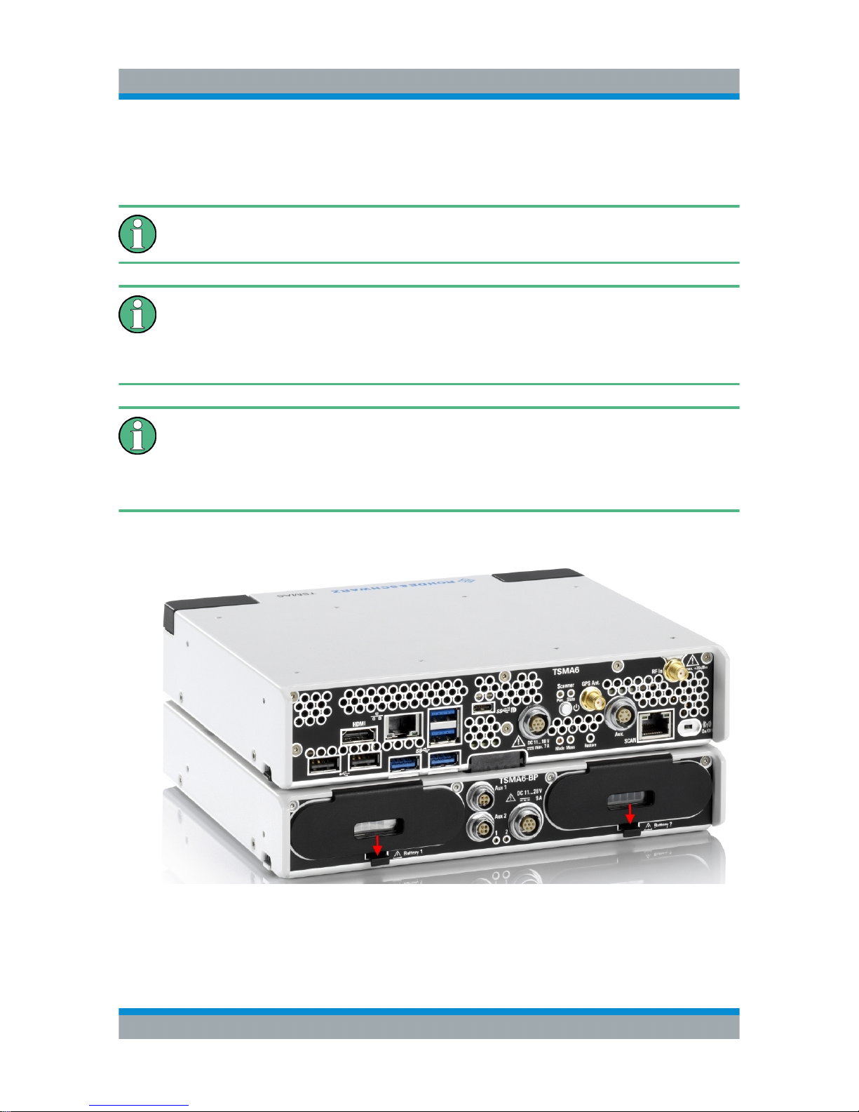
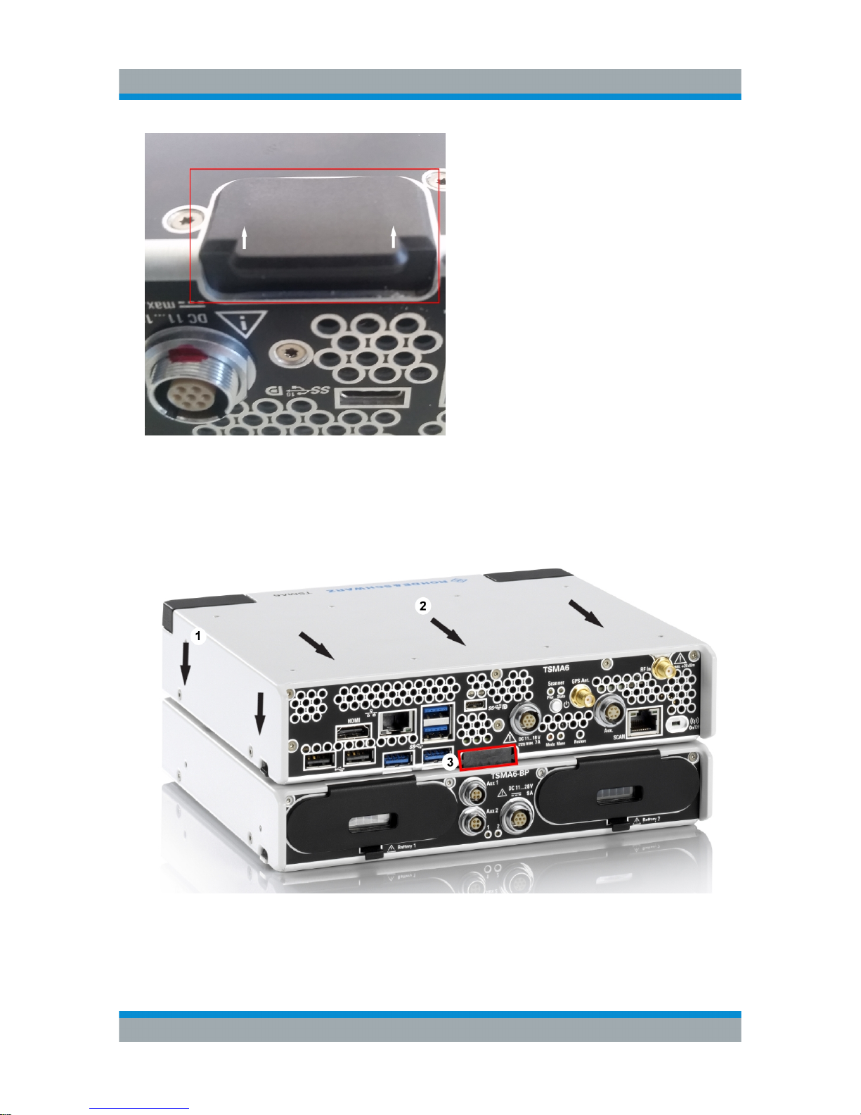
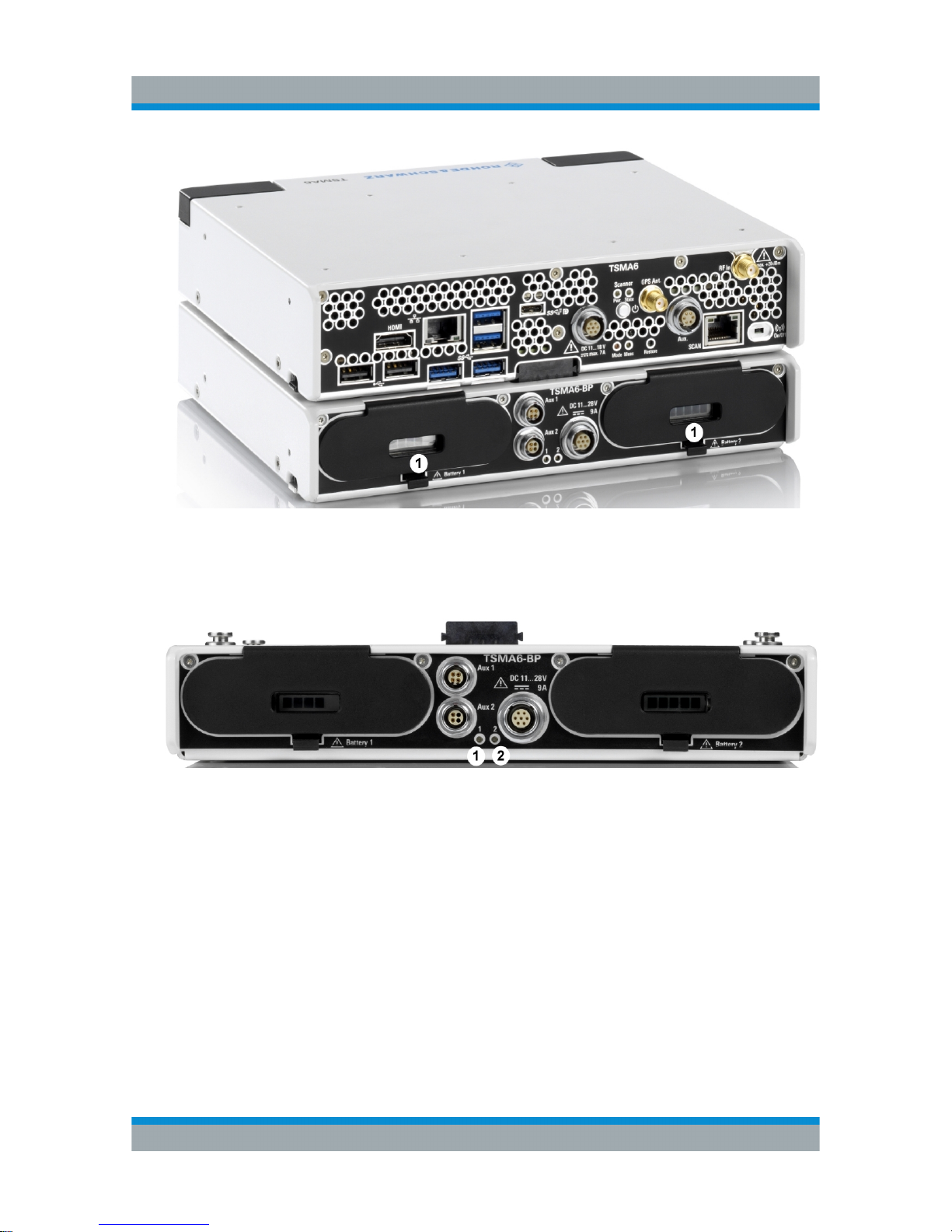
1. Screw the collar screws (1) on the top of the R&S TSMA6-BP with a Torx 8
screw driver.
● Torque: 0.66 Nm ± 0.05 Nm
Figure 4-3: R&S TSMA6-BP
1 = Collar screws for connecting R&S TSMA6
2 = Power connector for R&S TSMA6
3 = Aux 1 / Aux 2
4 = DC IN
5 = Status LEDs for battery 1 and 2
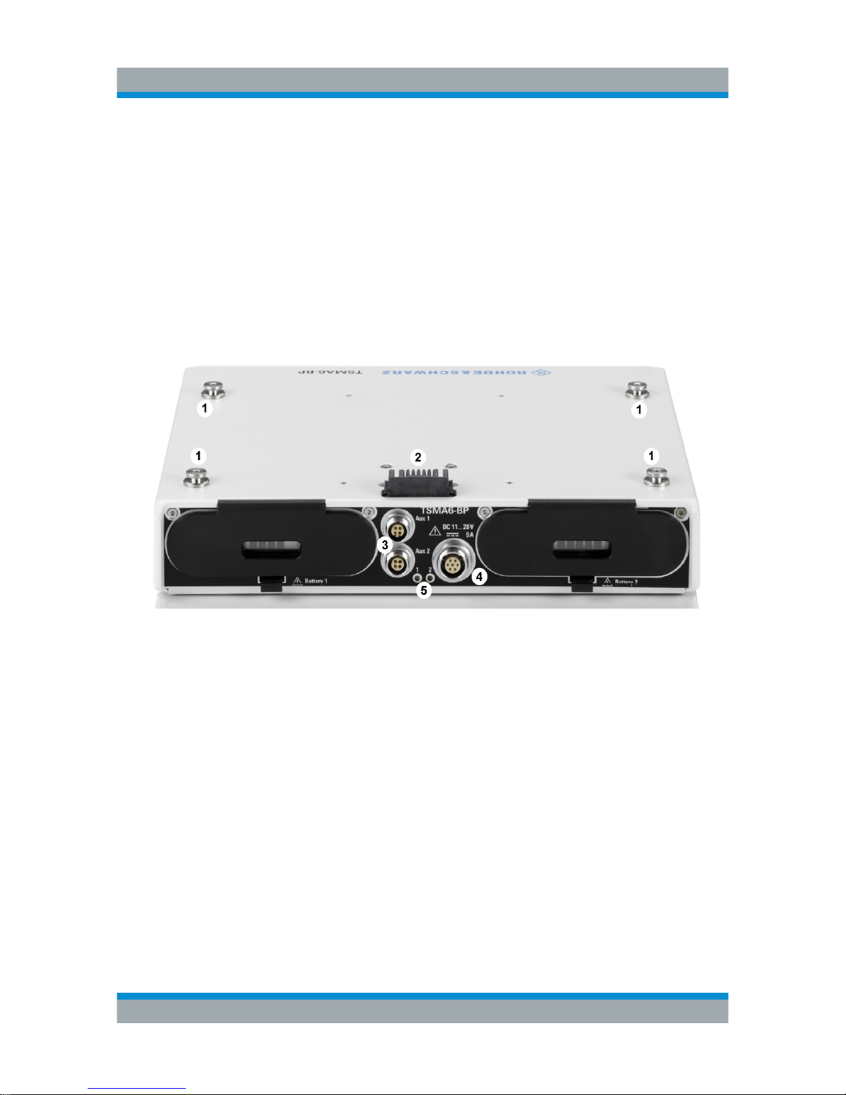
2. Remove the cover cap from the power connector of the R&S TSMA6.
Connecting the R&S TSMA6-BP with R&S TSMA6
Preparing for Use
R&S®TSMA6-BP
13Getting Started 4900.9030.02 ─ 03
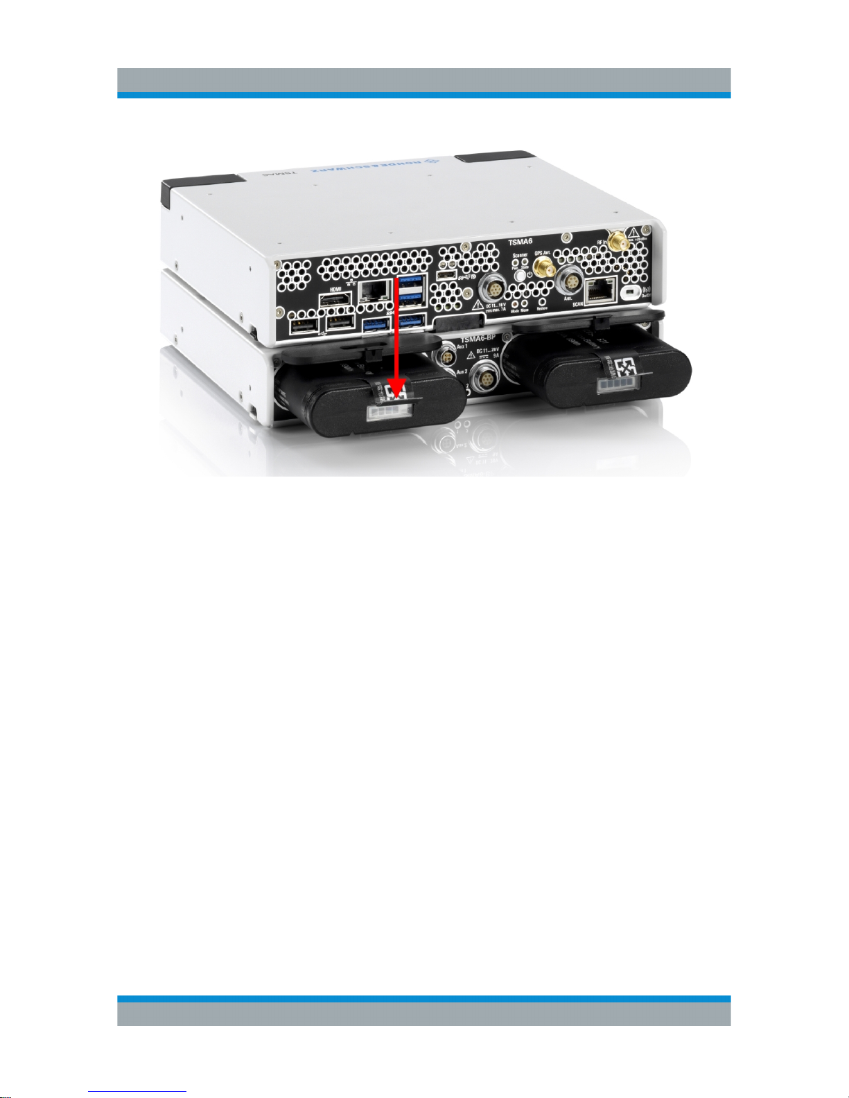
3. Attach the R&S TSMA6 with the bottom side (see Figure 4-4 ) on top of the
R&S TSMA6-BP (see Figure 4-3).
4. Move the R&S TSMA6 to the front side (2) until you hear a click when the connectors are locked.
Figure 4-4: Connected R&S TSMA6 Base Unit and R&S TSMA6-BP
1 = Attach R&S TSMA6 base unit to R&S TSMA6-BP
2 = Move R&S TSMA6 base unit to the front side
3 = Power Connection established
Connecting the R&S TSMA6-BP with R&S TSMA6

Preparing for Use
R&S®TSMA6-BP
14Getting Started 4900.9030.02 ─ 03
Disconnect Devices
To disconnect the R&S TSMA6-BP and the R&S TSMA6 base unit, lift the release
button (1) on both sides of the R&S TSMA6 base unit and slide it until the device
is released (2).
Figure 4-5: Disconnect devices
4.5 Connecting the R&S TSMA6-BP with R&S
TSME6
1. Screw the collar screws (1) on the top of the R&S TSMA6-BP with a Torx 8
screw driver.
● Torque: 0.66 Nm ± 0.05 Nm
Connecting the R&S TSMA6-BP with R&S TSME6

Preparing for Use
R&S®TSMA6-BP
15Getting Started 4900.9030.02 ─ 03
Figure 4-6: R&S TSMA6-BP
1 = Collar screws for connecting R&S TSME6
2 = Aux 1 / Aux 2 (Auxiliary power out for connecting R&S TSME6 / R&S TSME30DC via
power cable R&S TSME-ZYC (R&S No. 1514.7290.02)
3 = DC IN
4 = Status LEDs for battery 1 and 2
2. Attach the R&S TSME6 with the bottom side on top of the R&S TSMA6-BP.
3. Move the R&S TSME6 to the back side, until you hear a click when the connectors are locked.
Figure 4-7: Connected R&S TSME6 and R&S TSMA6-BP
1 = R&S TSMA6-BP
2 = R&S TSME6
4. Connect the R&S TSME6 DC IN with AUX1 or AUX 2 port of R&S TSMA6-BP
(see Figure 4-6) with the related DC cable (R&S TSME-ZYC, R&S No.
1514.7290.02 for up to 2 R&S TSME6 devices).
Connecting the R&S TSMA6-BP with R&S TSME6

Preparing for Use
R&S®TSMA6-BP
16Getting Started 4900.9030.02 ─ 03
The connection of up to 4 R&S TSME6 devices is possible. In this case, use two
R&S TSME-ZYC cables connected to AUX 1 and AUX 2. Each of these cables is
connected to 2 R&S TSME6 devices.
Disconnect Device
For disconnecting the devices, see "Disconnect Devices" on page 14.
Connecting the R&S TSMA6-BP with R&S TSME6

Operation
R&S®TSMA6-BP
17Getting Started 4900.9030.02 ─ 03
5 Operation
In the standard operation mode, it is recommended to use always two batteries with a comparable charging state (the batteries are discharged in parallel).
5.1 Operation Modes
●
Standalone Mode
In the standalone mode, the battery pack unit is used without an R&S TSMA6.
The charging display is autonomous.
●
TSMA6-controlled Mode
The R&S TSMA6 controls the LED display via the SMBus interface
5.2 LED Display
Figure 5-1: R&S TSMA6-BP - Status LEDs
1 (P601) = Status LED for battery 1
2 (P602) = Status LED for battery 2
Table 5-1: LED states and their meaning (LED 1 and LED 2) in standalone mode
Color LED State Comment
--- OFF Battery 1/2 not present
green BLINKING (2 Hz) Battery charged (100 %)
green ON Battery charging in progress /
external DC connected
LED Display

Operation
R&S®TSMA6-BP
18Getting Started 4900.9030.02 ─ 03
Table 5-2: LED states and their meaning (LED 1 and LED 2) in TSMA6-controlled mode
Mode Color State Comment
No battery --- OFF Battery 1/2 not
present
Battery powered /Full
charge
blue ON Charging state >
21%
Battery powered / Low
charge
blue BLINKING (0.5 Hz) 20 % > Charging
state > 10%
Battery powered / Critical
charge
blue BLINKING (2 Hz) Charging state <
10%
External
Power /
Charging
green ON Battery 1/2 charg-
ing in progress
External
Power /
Charging finished
green BLINKING (2 Hz) Battery 1/2 charg-
ing completed
Misc cyan BLINKING (5 Hz) any other repor-
ted state, e.g. battery error
5.3 Monitoring Battery Charge State
When inserted in the bay of the R&S TSMA6-BP, the battery charging state can
be monitored via the following possibilities:
●
Via state of charge battery display (1).
Monitoring Battery Charge State
Operation
R&S®TSMA6-BP
19Getting Started 4900.9030.02 ─ 03
Figure 5-2: R&S TSMA-BAT ((R&S No.1321.3772.00))
1 = Charging state display
●
Via front panel LEDs
Figure 5-3: R&S TSMA6-BP - Status LEDs
1 (P601) = Status LED for battery 1
2 (P602) = Status LED for battery 2
●
Via R&S TSMA6 web-GUI. For details, refer to "R&S TSMA6 Autonomous
Mobile Network Scanner - User Manual" (R&S No. 4900.8057.02).
5.4 Battery Exchange - Hot Swapping
The batteries can be exchanged during powering the R&S TSMA6 (hot-swap feature).
Battery Exchange - Hot Swapping

Operation
R&S®TSMA6-BP
20Getting Started 4900.9030.02 ─ 03
The batteries are both discharged evenly. Therefore, when batteries enter
low charge state, it is recommended to replace both batteries.
In case of a hot-swap, do not exchange the batteries simultaneously.
1. Open the cover of battery bay 1.
Figure 5-4: Open cover
2. Remove the battery by the tab.
Battery Exchange - Hot Swapping
Operation
R&S®TSMA6-BP
21Getting Started 4900.9030.02 ─ 03
Figure 5-5: Remove battery
3. Insert a charged battery.
4. Close the cover of battery bay 1.
5. Repeat step 1 to step 4 for battery bay 2.
Battery Exchange - Hot Swapping

Index
R&S®TSMA6-BP
22Getting Started 4900.9030.02 ─ 03
Index
B
Brochures .................................................. 6
D
Data sheets ............................................... 6
G
Getting started ...........................................6
H
Hot swap ................................................. 19
L
LED display ............................................. 17
LED states
standalone mode ................................ 17
TSMA6-controlled mode ..................... 18
O
Operation mode
Standalone ..........................................17
TSMA6-controlled ............................... 17
S
Safety instructions ..................................... 6
 Loading...