

Page 1
®
R&S
SZU100A
IQ Upconverter
58.32-64.8 GHz
Manual
(>INË2)
1425306102
Manual
Version 04
Page 2

This document describes the R&S®SZU100A, stock. no. 1425.3003.02 and its
options:
●
R&S®SZU-B1066 (1425.3110.02)
© 2019 Rohde & Schwarz GmbH & Co. KG
Mühldorfstr. 15, 81671 München, Germany
Phone: +49 89 41 29 - 0
Fax: +49 89 41 29 12 164
Email: [email protected]
Internet: www.rohde-schwarz.com
Subject to change – Data without tolerance limits is not binding.
R&S® is a registered trademark of Rohde & Schwarz GmbH & Co. KG.
Trade names are trademarks of the owners.
1425.3061.02 | Version 04 | R&S®SZU100A
The following abbreviations are used throughout this manual: R&S®SZU100A is abbreviated as R&S SZU,
the R&S®SMW200A is abbreviated as R&S SMW, the R&S®ZCTW is abbreviated as R&S ZCTW.
Page 3

R&S®SZU100A
Contents
1 Safety Information................................................................. 5
2 Documentation Overview......................................................6
3 About This Manual.................................................................7
4 Welcome to the R&S SZU..................................................... 8
5 Preparing for Use.................................................................10
5.1 Unpacking and Checking the R&S SZU............................................10
5.2 Putting into Operation........................................................................ 11
Contents
5.3 Adjusting the Feet...............................................................................12
6 Instrument Tour................................................................... 13
6.1 Front View............................................................................................13
6.2 Rear View.............................................................................................14
6.2.1 Power Supply Connector...................................................................... 15
6.2.2 IQ Input Connectors..............................................................................16
6.2.3 Status LED............................................................................................16
6.2.4 USB Interface........................................................................................17
6.2.5 LO In/Out Connectors........................................................................... 17
6.2.6 Trigger Input/Output Connector............................................................ 17
7 Startup.................................................................................. 18
7.1 System Requirements........................................................................ 19
7.2 Measurement Setup............................................................................20
7.3 Starting Up...........................................................................................22
7.4 Running Internal Adjustments...........................................................30
7.5 Behavior of the R&S SMW When Working with the R&S SZU........32
3Manual 1425.3061.02 ─ 04
Page 4

R&S®SZU100A
8 Remote Control of the R&S SZU........................................ 36
Glossary: List of Frequently Used Terms and Abbrevia-
tions...................................................................................... 38
Index..................................................................................... 40
Contents
4Manual 1425.3061.02 ─ 04
Page 5

R&S®SZU100A
Safety Information
1 Safety Information
The product documentation helps you use the R&S SZU safely and efficiently.
Follow the instructions provided here and in the printed "Basic Safety Instructions". Keep the product documentation nearby and offer it to other users.
Intended use
The R&S SZU is intended for the development, production and verification of
electronic components and devices in industrial, administrative, and laboratory
environments. Use the R&S SZU only for its designated purpose. Observe the
operating conditions and performance limits stated in the data sheet.
Where do I find safety information?
Safety information is part of the product documentation. It warns you about the
potential dangers and gives instructions how to prevent personal injuries or damage caused by dangerous situations. Safety information is provided as follows:
●
The printed "Basic Safety Instructions" provide safety information in many languages and are delivered with the R&S SZU.
●
Throughout the documentation, safety instructions are provided when you
need to take care during setup or operation.
5Manual 1425.3061.02 ─ 04
Page 6

R&S®SZU100A
Documentation Overview
2 Documentation Overview
This section provides an overview of the R&S SZU user documentation. You find
it on the product page of the R&S SZU, see www.rohde-schwarz.com/manual/
szu100a. The User Manual of the R&S SMW is provided at www.rohdeschwarz.com/product/SMW200A/User Manual.
The user documentation for the R&S SZU consists of the following parts:
Manual
Introduces the R&S SZU and describes how to set up and start working with the
product. Includes basic operation and general information, e.g. safety instructions, etc. A printed version is delivered with the instrument.
Online help
The online help offers quick, context-sensitive access to the complete information
for the base unit and the software options directly on the R&S SMW.
General safety instructions
The brochure delivered with the instrument contains basic safety instructions and
operating conditions and further important information.
Data sheet and brochure
The data sheet contains the technical specifications of the R&S SZU. It also lists
the options and their order numbers and optional accessories.
A brochure provides an overview of the instrument and deals with the specific
characteristics.
See www.rohde-schwarz.com/brochure-datasheet/szu100a.
Release notes and open source acknowledgment (OSA)
The release notes list new features, improvements and known issues of the current firmware version, and describe the firmware installation.
The open source acknowledgment document provides verbatim license texts of
the used open source software.
6Manual 1425.3061.02 ─ 04
Page 7

R&S®SZU100A
About This Manual
3 About This Manual
This user manual which you have received as printed book with your instrument,
provides all the specific information about the R&S SZU. The instrument functions
and settings concerning the R&S SMW are described in the main R&S SMW user
manual.
The main focus is on the tasks required for setting up the measurement system.
The following topics are included:
●
Welcome to the R&S SZU IQ Upconverter
Introduction to and getting familiar with the instrument.
●
Preparing for use
Basic steps to be taken when setting up the R&S SZU IQ Upconverter for the
first time.
●
Startup
Description on how to take the R&S SZU IQ Upconverter into operation.
●
Remote control
Remote control commands related to the R&S SZU, see the R&S SMW user
manual.
●
Glossary
Alphabetical list of frequently used terms and abbreviations
7Manual 1425.3061.02 ─ 04
Page 8

R&S®SZU100A
Welcome to the R&S SZU
4 Welcome to the R&S SZU
The Rohde & Schwarz R&S SZU is an IQ upconverter designed for the 60 GHz
frequency band. These frequencies are used in modern high-performance wireless communication standards, e.g. IEEE802.11 ad. Operating in the 60 GHz frequency band enables devices to communicate at multi-gigabit speed, with data
transfer rates of several Gbit/s.
Key features
The R&S SZU IQ Upconverter features:
●
Compact broadband upconverter providing 57 GHz to 66 GHz frequency
●
Power output of at least 5 dBm for over the air (OTA) RF measurements and
tests
●
Adjustable output power in the range +5 dBm to -80 dBm, with integrated level
detector
●
RF output signal at the waveguide port
●
Support of common mountable test port adapters
●
High-level stability and harmonic suppression
●
Compatible to all R&S SMW frequency options
●
Support of the R&S SMW output level user correction
●
Fully calibrated at the waveguide port
●
Control via user interface of the R&S SMW
●
Small size, easy usage, and operation in any position possible
About the R&S SZU IQ Upconverter
The R&S SZU generates a vector-modulated signal by converting the baseband
signal to the output frequency range of 58.32 GHz to 64.8 GHz (center frequency).
The R&S SZU receives the differential or single ended baseband signals (I/Q),
and an LO signal in the range of 1.944 GHz to 2.16 GHz from the R&S SMW.
The USB host interface is the communication port of the R&S SZU to the
R&S SMW. As external instrument, the R&S SZU is configured in the "System
Configuration" dialog of the R&S SMW, and indicated by a symbol in the GUI.
Once connected, the R&S SMW reads the calibration data of the R&S SZU, and
8Manual 1425.3061.02 ─ 04
Page 9

R&S®SZU100A
adjusts the frequency and level values to the output values of this downstream
instrument.
Thus the R&S SMW controls the R&S SZU almost entirely. You only need to
select single ended or differential mode for the baseband connection. It is recommended that you work in differential mode due to better common mode noise
suppression over the single ended connection. When you work with two
R&S SZUs on one R&S SMW, you must work in single ended mode.
The setting parameters in the R&S SMW remain the same.
Welcome to the R&S SZU
9Manual 1425.3061.02 ─ 04
Page 10
R&S®SZU100A
Unpacking and Checking the R&S SZU
Preparing for Use
5 Preparing for Use
This section explains how to take an R&S SZU IQ Upconverter into operation. It
includes the controls and connectors of the R&S SZU, and provides all the information necessary for connection.
For information on the equipment required for a basic test setup, see Chapter 7.1,
"System Requirements", on page 19.
5.1 Unpacking and Checking the R&S SZU
To remove the instrument from its packaging and to check the equipment for completeness, proceed as follows:
1. Unpack the R&S SZU and the other contents of the shipping container.
2. Check the equipment for completeness using the delivery list.
3. Remove the protective cap from the waveguide port at the front of the
R&S SZU. Inspect the instrument carefully, to make sure that it has no damage from shipment.
If there is any damage, immediately contact the freight forwarder, who has
delivered the instrument.
Packaging material
It is recommended that you retain the original packaging material. If the
R&S SZU needs to be transported or shipped later, you can use the material to prevent control elements and connectors from being damaged.
Equipment returned or sent in for repair must be packed in an appropriate
packaging, if the original packaging is no longer available.
Also use the packaging material for storage of the instrument and the
accessories.
10Manual 1425.3061.02 ─ 04
Page 11

R&S®SZU100A
Preparing for Use
Putting into Operation
5.2 Putting into Operation
The IQ upconverter is designed for use under laboratory conditions.
General ambient conditions:
●
The ambient temperature and humidity must be in the ranges specified for
operation and for compliance with specifications (see the data sheet).
●
Condensed humidity can cause serious defects to the hardware. To avoid
condensed humidity, keep the warm-up time for the R&S SZU to adjust to the
ambient temperature.
●
All ventilation openings must be unobstructed.
Risk of instrument and DUT damage
To avoid damage of electronic components of the DUT and the R&S SZU,
protect the operating site against electrostatic discharge (ESD).
11Manual 1425.3061.02 ─ 04
Page 12
R&S®SZU100A
Preparing for Use
Adjusting the Feet
5.3 Adjusting the Feet
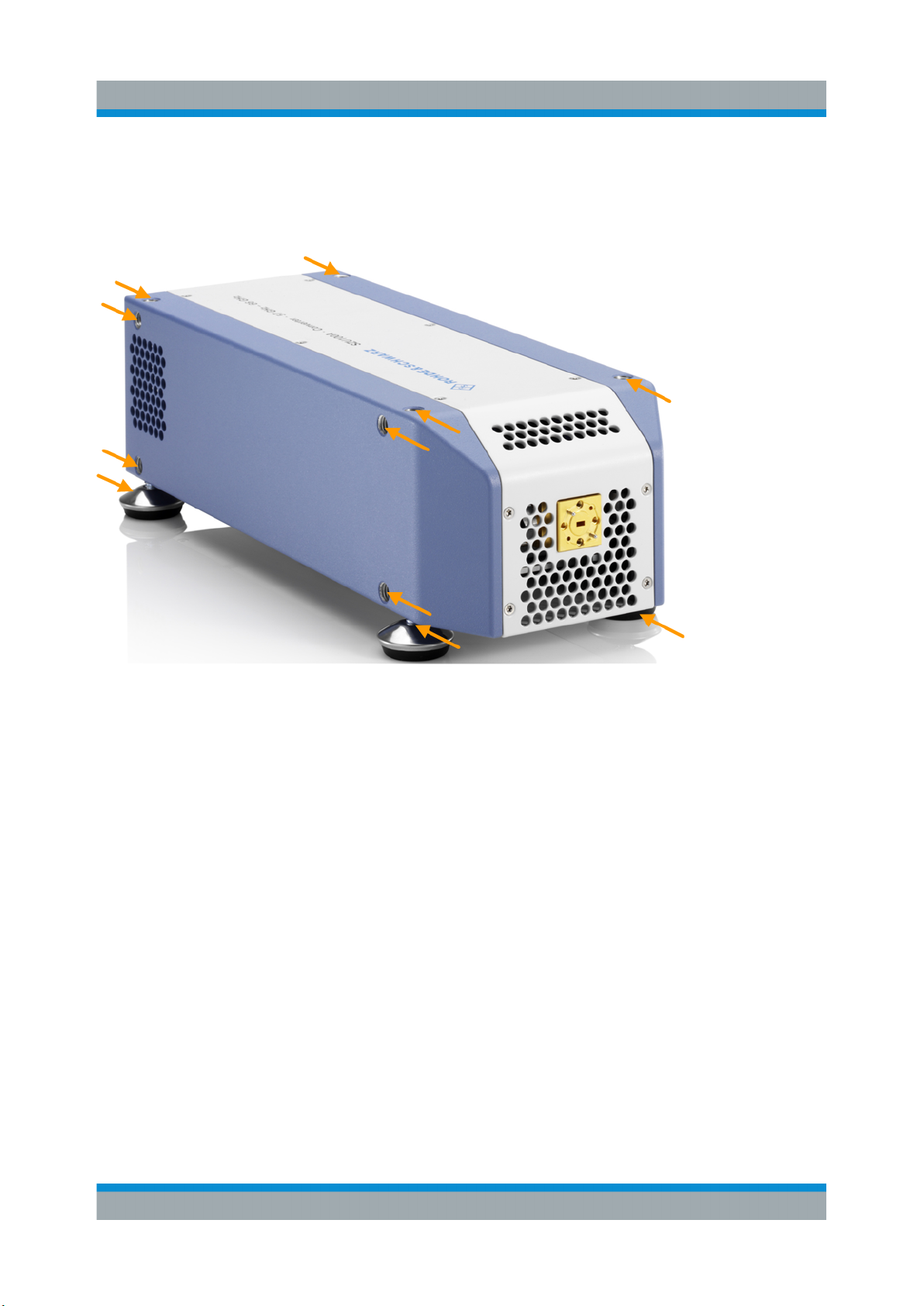
The R&S SZU has four adjustable feet you can mount at each side of the unit.
12Manual 1425.3061.02 ─ 04
Page 13
R&S®SZU100A
Instrument Tour
Front View
6 Instrument Tour
6.1 Front View
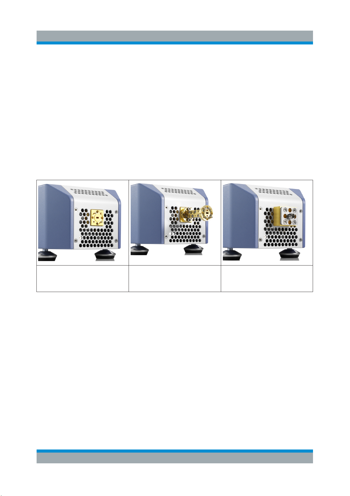
Test port adapter (waveguide port)
At the front, the R&S SZU covers the interface to the DUT, that is the output of the
RF signal.
Table 6-1: R&S SZU IQ Upconverter front views
R&S SZU with standard WR15
waveguide flange, without any
adapter
To avoid damage as a result of wear and tear of the waveguide port, it is recommended that you mount a test port adapter for the corresponding frequency band.
The precision waveguide flange of the test port adapter is equipped with two
alignment pins and two holes that receive the alignment pins of the DUT. Two
additional holes in the middle allow you to insert additional alignment of pins that
are included. Use the extra pins, when the flange of the DUT provides the corresponding holes. In particular, if the DUT has thin pins, these additional pins
improve the alignment and stability of the connection.
R&S SZU with test port
adapter
R&S SZU with waveguide to
V-connector adapter
13Manual 1425.3061.02 ─ 04
Page 14
R&S®SZU100A
Instrument Tour
Rear View
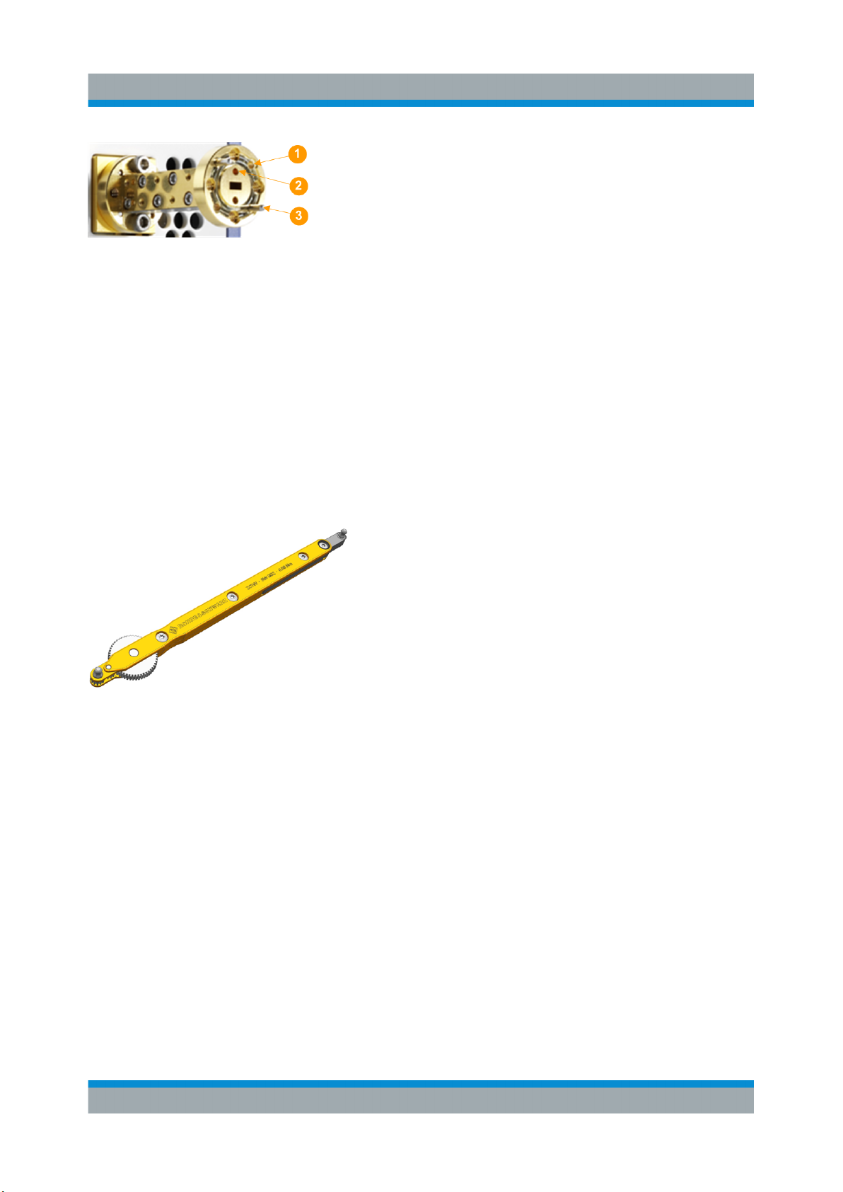
Figure 6-1: Assignment of the test port adapter
1 = Hole for pin of the DUT
2 = Hole for additional pin
3 = Alignment pin
Refer to the data sheet for more details on the type of waveguide port.
Mounting the test port adapter
Mount the selected adapter to the waveguide port of the instrument using the
delivered screws and the special torque wrench for waveguide flange screws.
The R&S ZCTW (order no. 1175.2014.02) is especially designed for these tasks.
Figure 6-2: Recommended torque wrench R&S ZCTW
6.2 Rear View
The rear panel of the R&S SZU provides the connectors and control elements
described below:
●
Power Supply Connector
●
IQ Input Connectors
●
Status LED
●
USB Interface
●
LO In/Out Connectors
●
Trigger Input/Output Connector
14Manual 1425.3061.02 ─ 04
Page 15

R&S®SZU100A
Instrument Tour
Rear View
Figure 6-3: Rear view of the R&S SZU
1 = Power supply connector
2 = IQ input connectors
3 = Status LED
4 = USB interface
5 = LO signal input and output
6 = Trigger connector
6.2.1 Power Supply Connector
Connection for the DC power supply (Figure 6-3, (1)).
The IQ upconverter is supplied by an external DC power supply. It supports the
AC input voltages between 100 V to 240 V and frequencies between 50 Hz to
60 Hz.
15Manual 1425.3061.02 ─ 04
Page 16

R&S®SZU100A
Shock hazard
The input voltage and current must not exceed the maximum values
according to the labeling or the data sheet. It is recommended that you use
the included power supply unit for the operation of the R&S SZU.
When other than the included power supply is used to supply the equipment
with DC safety extra low voltage (SELV), the requirement for strengthened /
double insulation in line with DIN/EN/IEC 61010 (UL61010, CAN CSA
C22.2 No. 61010) or DIN/EN/IEC 60950 (UL60950, CAN CSA C22.2 No.
60950) must be met.
6.2.2 IQ Input Connectors
Instrument Tour
Rear View
Input connectors for the single ended (I/Q) or differential (I/Q, I/Q BAR) baseband
signal (Figure 6-3, (2)).
The I/Q input connectors receive the single-ended signal, or the positive signal
components of the differential signal. The I/Q BAR connectors receive the negative signal components of the differential signal.
6.2.3 Status LED
Indicates the instrument status (Figure 6-3, (3)).
Table 6-2: The status of the R&S SZU indicated by the color of LED
LED R&S SZU status Description
off
on
blinking (3 Hz)
on
Off R&S SZU is powerless.
Standby Controller is running, all analog circuity are pow-
ered down.
Booting or busy Controller is booting or USB transfer is running.
RF Off R&S SZU is ready for operation with RF deactiva-
ted.
on
blinking once
RF On R&S SZU is ready for operation with RF signal
activated.
Trigger received LED switches off for 200 µs when an external trig-
ger event occurred.
16Manual 1425.3061.02 ─ 04
Page 17

R&S®SZU100A
LED R&S SZU status Description
Instrument Tour
Rear View
on
blinking (6Hz)
Internal error E.g. over temperature, power failure, fan failure.
External error E.g. LO level out of range.
6.2.4 USB Interface
Universal serial bus (USB) interface of type B (Figure 6-3, (4)). This port is used
to communicate with the host instrument, the R&S SMW.
6.2.5 LO In/Out Connectors
Connectors for RF signal input and output (Figure 6-3, (5)). These connectors are
SMA coaxial connectors with 50 Ohm impedance. LO In receives the LO signal
from the R&S SMW, and LO Out is intended for future use, e.g. to forward the LO
signal when using multiple R&S SZU in a daisy chain.
Risk of instrument damage
The RF input power at the connector LO In must not exceed the maximum
values specified in the data sheet.
6.2.6 Trigger Input/Output Connector
Connector for an optional trigger signal (Figure 6-3, (6)). The trigger connector is
an SMA coaxial connector with 50 Ohm impedance.
17Manual 1425.3061.02 ─ 04
Page 18

R&S®SZU100A
Startup
7 Startup
This section explains the required steps and components for starting up with
R&S SZU. It describes how to connect the IQ upconverter with the R&S SMW,
what you have to observe and how to configure the system in the R&S SMW.
Risk of instrument damage during operation
An unsuitable operating site or test setup can damage the instrument and
connected devices. Make sure that the following operating conditions are
met, before you switch on the instrument:
●
All fan openings are unobstructed and the airflow perforations are unimpeded. The recommended distance from the wall is 10 cm.
●
The instrument is dry and shows no sign of condensation.
●
The instrument is adjusted to the ambient temperature, i.e. the warm-up
time was kept.
●
The ambient temperature and humidity do not exceed the ranges specified in the data sheet.
●
Signal levels at the input connectors are all within the specified ranges.
The R&S SZU IQ Upconverter is designed and tested in accordance with the EC
certificate of conformity and has left the manufacturer’s plant in a condition fully
complying with safety standards.
To maintain this condition and to provide safe operation, observe all instructions
and warnings given in the following description.
RF input power
The RF input power at the connector LO In must not exceed the maximum values
quoted in the data sheet.
The R&S SZU is operated only in combination with the R&S SMW, which adjusts
the LO signal level at any time to the optimum for the R&S SZU. Note, that the
recommended firmware versions are installed on both instruments.
18Manual 1425.3061.02 ─ 04
Page 19

R&S®SZU100A
System Requirements
Protection of waveguide flanges
Protect the waveguide flanges of the IQ upconverter against mechanical damage.
Always use a torque wrench to tighten the screws of the waveguide flanges.
Shield the waveguides from dust and moisture, and avoid scratching the contact
surfaces. We recommend that you use a test port adapter.
When the IQ upconverter is not in use, leave the test port adapter mounted and
attach one of the included protective caps to the adapter.
Avoid heavy shocks
Heavy shocks can damage the hardware of the IQ upconverter.
For shipping or storing the device, make sure that it is packed with shockproof
packaging materials in a sturdy cardboard box of suitable size, see also "Packag-
ing material" on page 10.
Startup
7.1 System Requirements
To operate an IQ upconverter, you need:
●
An R&S SZU IQ Upconverter.
●
The R&S SMW as signal source, which can generate the local oscillator signal
within the frequency range of your R&S SZU and a level as specified in the
data sheet.
●
A test port adapter, if necessary.
●
Cables set:
– Four I/Q cables, included
– An RF cable, included
– The USB cable, included
– A trigger cable, optionally
19Manual 1425.3061.02 ─ 04
Page 20

R&S®SZU100A
Measurement Setup
Electromagnetic interference (EMI) affects the measurement results
To suppress generated electromagnetic interference:
●
Only use the enclosed cables set, as the R&S SZU has been calibrated
with these cables.
You can find out the corresponding cable set by the serial number,
which is the same as the serial number of the R&S SZU.
●
Always terminate open cable ends:
– Terminate the waveguide output with 50 Ohm.
If it is not possible to terminate the output with 50 Ohm, leave it
open.
– Instead of terminating with 50 Ohm, you can connect a wideband
power sensor of the R&S NRPxx series, which also provides a good
termination.
●
Use only the USB cable included.
Startup
●
Note the EMC classification in the data sheet.
7.2 Measurement Setup
This section provides the first steps for putting the R&S SZU into operation. The
startup also comprises the access to the settings made in the R&S SMW.
Risk of RF connector and cable damage
Excessive tightening of the connectors can damage the cables and connectors. Too weak tightening leads to inaccurate results.
Always use the torque wrench suitable for this type of connector, see
"Mounting the test port adapter" on page 14.
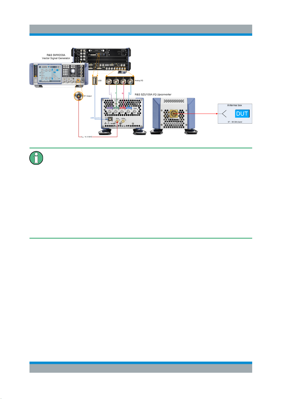
The figure shows the basic test setup of an application with the R&S SZU IQ
Upconverter. The R&S SMW controls the R&S SZU via USB. The R&S SMW also
provides the analog baseband signal, and a trigger signal optionally. The
R&S SZU transmits the upconverted I/Q signal to the antenna box (DUT).
20Manual 1425.3061.02 ─ 04
Page 21
R&S®SZU100A
Measurement Setup
When setting up the measurement, it is recommended that you consider the
following:
Startup
●
Use only the supplied cables, as described in Electromagnetic interfer-
ence (EMI) affects the measurement results.
●
Connect the instruments in the given order. In particular, connect the
baseband signals before starting up.
●
Switch off the RF of the R&S SMW before connecting the R&S SZU, to
prevent damage of the R&S SZU due to high input power.
●
Make sure that the input power level is always less than the maximum
level specified in the data sheet.
To set up the measurement...
1. Power on the R&S SMW vector signal generator.
2. Connect the IQ outputs of the signal generator to I/Q connectors of the
R&S SZU.
3. Connect the RF A output of the signal generator to LO In of the IQ
upconverter.
4. Connect the USB cable plug B to the R&S SZU, and the USB cable plug A to
the R&S SMW.
5. Connect the R&S SZU IQ Upconverter to the power supply.
6. Keep the Warm-up time.
21Manual 1425.3061.02 ─ 04
Page 22

R&S®SZU100A
7. Before connecting to the DUT, configure the R&S SZU in the R&S SMW, see
Starting Up.
With connecting USB, the R&S SMW recognizes the R&S SZU automatically.
The R&S SMW reads all parameters for identification and the calibration table
of the R&S SZU, and sets the optimum LO level.
At a reboot with a connected R&S SZU, RF can remain active, since the
R&S SMW starts with the last used settings.
Startup
Starting Up
7.3 Starting Up
After connecting the instruments, you need to configure the connection in the
"System Configuration" dialog of the R&S SMW. The following instruction guides
you through the first steps by the example of one connected IQ Upconverter,
assigned to path A.
Another example shows two R&S SZUs connected to the R&S SMW, i.e. one per
path, see "Two R&S SZU connected to the R&S SMW" on page 28.
For details to the setting parameters and to the corresponding remote control commands, refer to:
●
The www.rohde-schwarz.com/product/SMW200A/User Manual, chapter
"Signal Routing and System Configuration", sections "System Configuration Settings > External RF and I/Q Settings", and section "System
Configuration Settings > Overview".
●
Chapter 8, "Remote Control of the R&S SZU", on page 36, and the
corresponding descriptions in the R&S SMW user manual.
To configure the R&S SZU in the R&S SMW ...
Access:
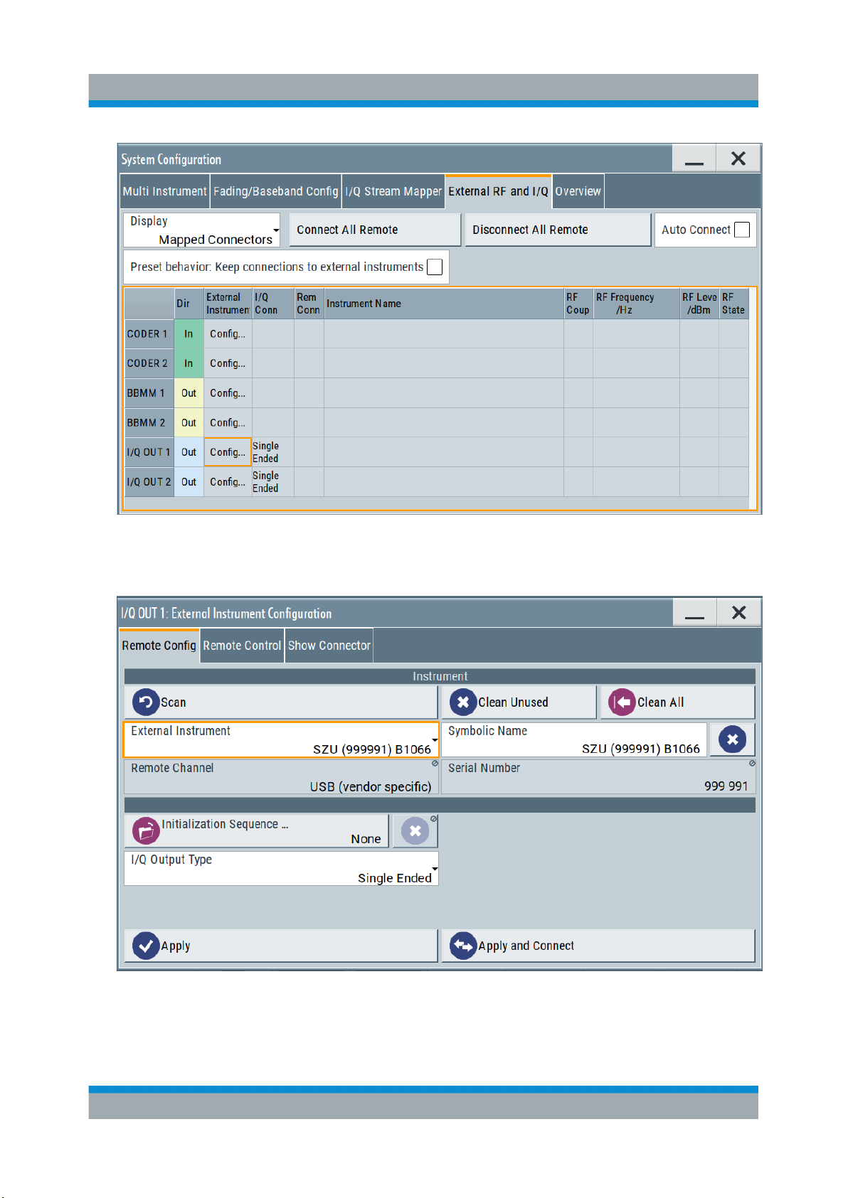
1. Select "Taskbar > System Config. > System Configuration > External RF and
I/Q".
22Manual 1425.3061.02 ─ 04
Page 23
R&S®SZU100A
Startup
Starting Up
2. Select "I/Q OUT 1 > Config...".
3. Select "External Instrument > SZU (<Serial No> Bxxxx)".
4. Select "I/Q Output Type > Differential".
Note: If you are working with an R&S SZU in each path, the R&S SMW only
supports the single ended mode in both paths.
23Manual 1425.3061.02 ─ 04
Page 24
R&S®SZU100A
Starting Up
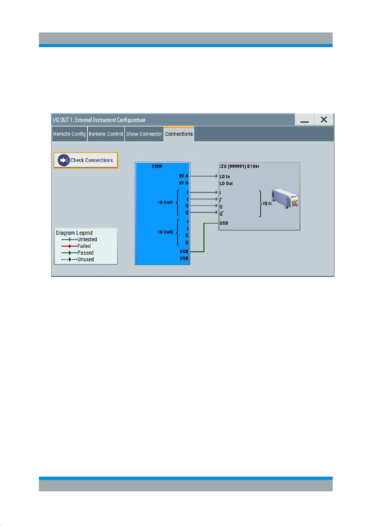
5. Confirm with "Apply and Connect".
The R&S SMW establishes the connection to the R&S SZU and shows the
"Connections" tab.
6. Select "Check Connections".
Startup
The R&S SMW checks the connections at the corresponding RF and I/Q connectors and displays the results.
7. Close the dialog.
24Manual 1425.3061.02 ─ 04
Page 25
R&S®SZU100A
Startup
Starting Up
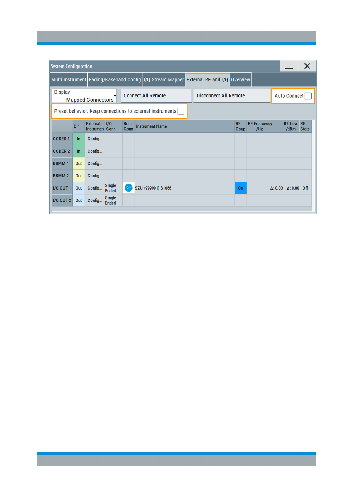
1 = see step 8
2 = see step 9
8. In the "System Configuration" dialog, check "Auto Connect".
When enabled, the R&S SMW automatically (re)establishes the connection to
the R&S SZU, e.g. after a restart or an instrument preset.
9. Select "Preset behavior: Keep connections to external instruments".
When enabled, the R&S SMW retains the connection to the R&S SZU at an
instrument preset, see Chapter 7.5, "Behavior of the R&S SMW When Work-
ing with the R&S SZU", on page 32.
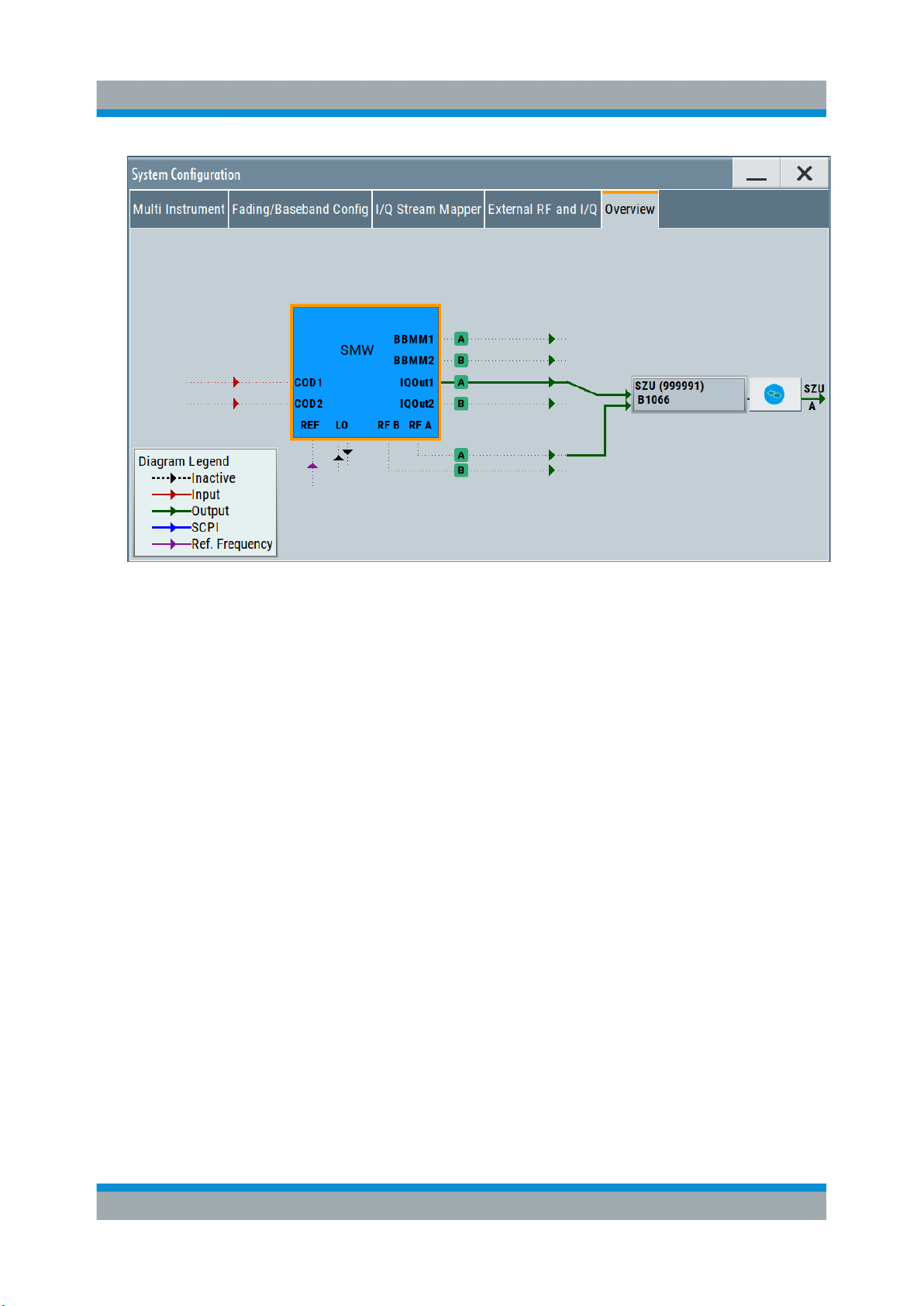
10. Select the "Overview" tab.
25Manual 1425.3061.02 ─ 04
Page 26
R&S®SZU100A
Startup
Starting Up
The overview tab shows all external instruments connected, in this case one
connected R&S SZU. For more, see the user manual of the R&S SMW, chapter "System Configuration Settings", section "Overview".
11. Close the dialog.
12. If necessary, perform an internal adjustment, before connecting the DUT and
activating the measurement.
Proceed as described in Chapter 7.4, "Running Internal Adjustments",
on page 30.
To activate the signal output...
After the internal adjustments are completed, you can connect the DUT and start
with your measurement.
1. Connect the R&S SZU with the DUT.
26Manual 1425.3061.02 ─ 04
Page 27
R&S®SZU100A
Startup
Starting Up
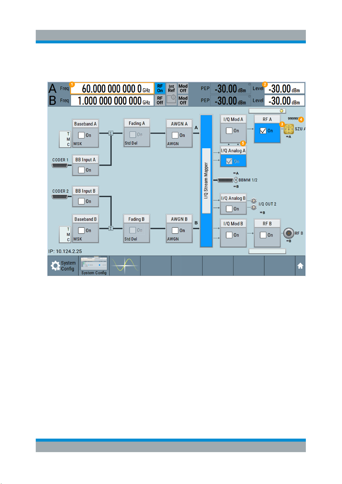
2. In the block diagram, select the checkbox in the "RF" to activate RF signal
output.
Figure 7-1: Display of one connected R&S SZU on the R&S SMW screen
1 = RF frequency of the R&S SZU RF output
2 = RF level, nominal level at the R&S SZU RF output (regulated level)
3 = RFLO, CW signal for the LO input of the R&S SZU
4 = R&S SZU displayed by the waveguide port icon, the label and the serial number
5 = Active I/Q output with displayed connection lines
The R&S SMW performs the following:
● Reads all parameters for identification of the R&S SZU.
● Reads the R&S SZU calibration data.
● Indicates the connected R&S SZU at the RF output in the block diagram
and displays the waveguide output icon.
● Sets the output signal level and frequency to the default values of the
R&S SZU, and indicates these values in the status bar. You can set both
parameters directly as usual.
27Manual 1425.3061.02 ─ 04
Page 28

R&S®SZU100A
Two R&S SZU connected to the R&S SMW
The R&S SMW supports one R&S SZU per path, i.e. you can connect another
R&S SZU also to path B or vice versa.
For the I/Q and RF ports of the two paths, the R&S SMW allows the following
combinations:
●
The I/Q signal of the analog I/Q out 1 and the LO output of RF path A
●
The I/Q signal of the analog I/Q out 2 and the LO output of RF path B
However, when you are working with two R&S SZU, you can process the IQ signals only in single-ended mode.
To configure two R&S SZU in one R&S SMW...
The connection and configuration of a second R&S SZU in the R&S SMW are the
same as described above.
Startup
Starting Up
► For the second instrument, proceed as described in "To configure the
R&S SZU in the R&S SMW ..." on page 22.
As an exception, consider step step 4. Select "I/Q Output Type > Single
Ended" in both paths instead.
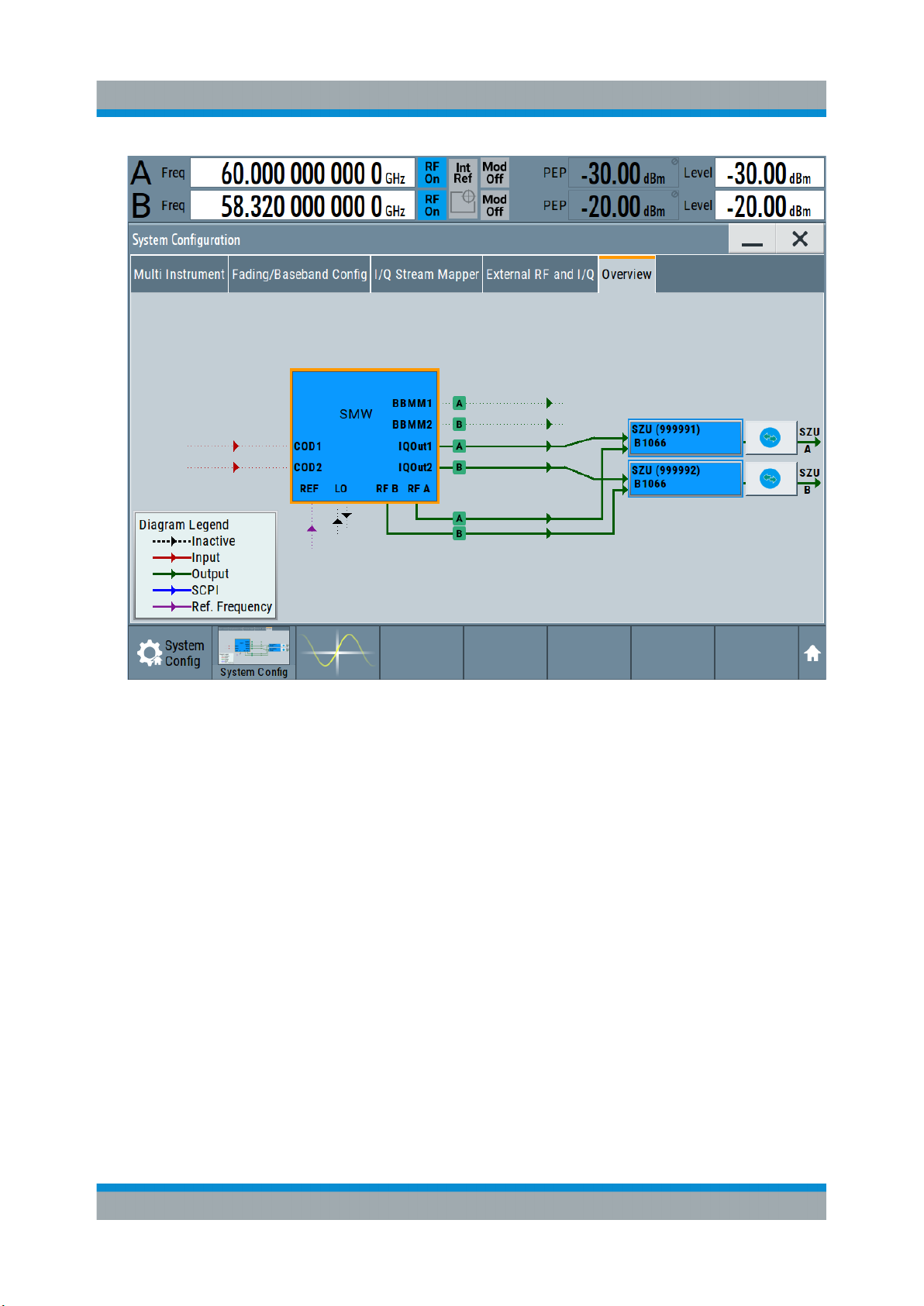
When completed, the R&S SMW indicates the two IQ upconverters as shown
in Figure 7-2, and Figure 7-3.
28Manual 1425.3061.02 ─ 04
Page 29
R&S®SZU100A
Startup
Starting Up
Figure 7-2: Overview tab with two connected R&S SZUs
29Manual 1425.3061.02 ─ 04
Page 30
R&S®SZU100A
Startup
Running Internal Adjustments
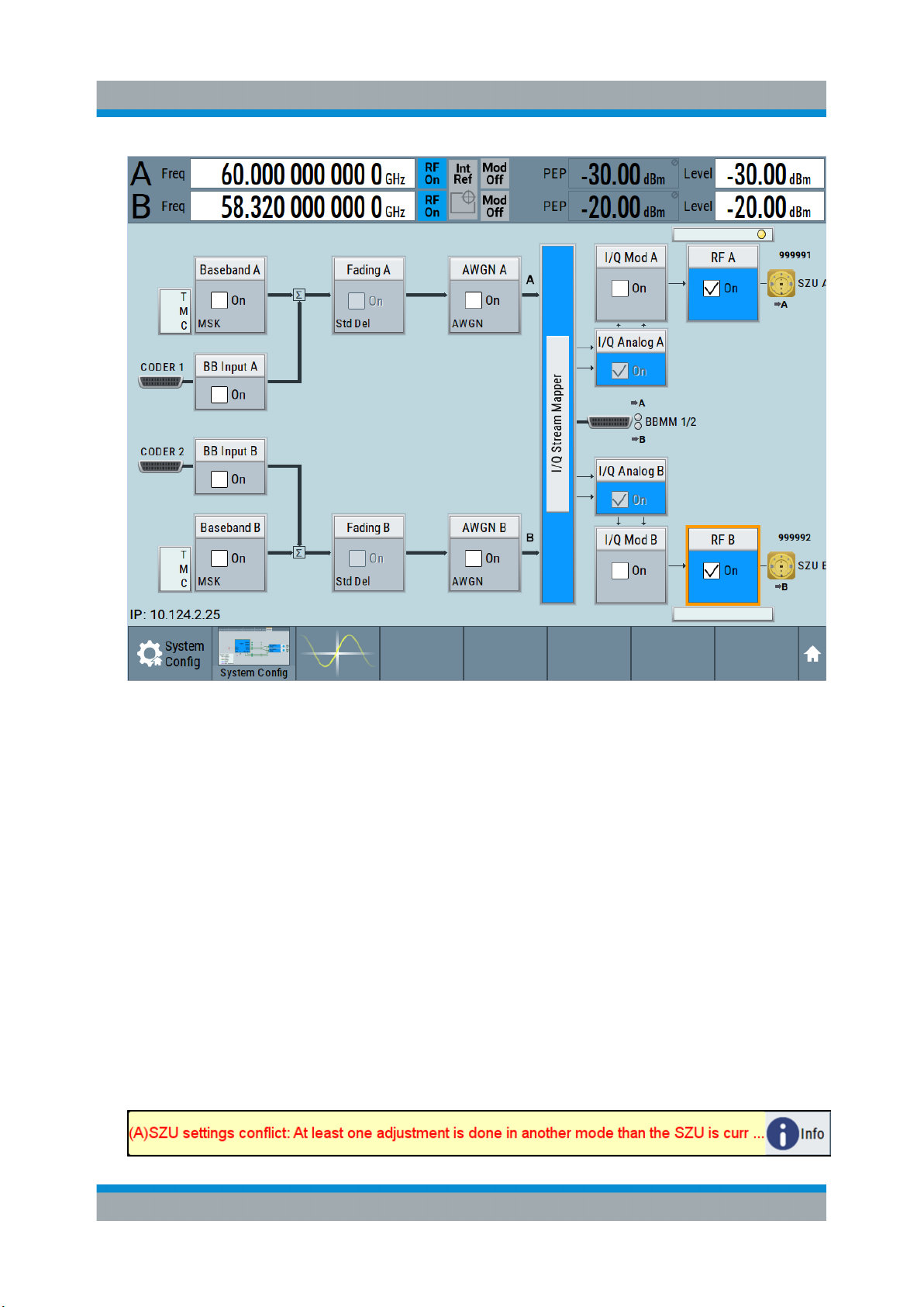
Figure 7-3: R&S SMW screen with an R&S SZU in both paths
7.4 Running Internal Adjustments
To optimize the accuracy for the application with the R&S SZU, you can execute
calibration routines directly in the R&S SMW.
When to perform the internal adjustments?
We recommend that you perform the internal adjustment:
●
When setting up an application the first time.
●
When changing the I/Q output type of an already set measurement.
When you have calibrated the R&S SZU with a different I/Q output type (single-ended / differential), the R&S SMW issues the warning message:
30Manual 1425.3061.02 ─ 04
Page 31

R&S®SZU100A
Running Internal Adjustments
"SZU settings conflict: At least one adjustment has been done in another
mode than the SZU is currently set to (single-ended / differential). Accuracy
may be affected!"
To adjust the R&S SZU ...
Set up the measurement, if not done yet. Observe the requirements as described
under Chapter 7.1, "System Requirements", on page 19:
1. Make sure that the serial number of the R&S SZU and the cables match.
2. Connect the R&S SZU to the R&S SMW, see Chapter 7.2, "Measurement
Setup", on page 20.
3. Make sure that:
● You have terminated the waveguide port properly, see Electromagnetic
interference (EMI) affects the measurement results.
Do not leave the protective cap plugged on the waveguide output either, as
it causes undefined reflections and thus leads to incorrect adjustments.
● No power is fed into the waveguide output during the internal adjustment
processes. It can be caused, e.g. by a connected spectrum analyzer which
emits LO power when operating in receiving mode.
Startup
4. Configure the R&S SZU in the R&S SMW, see Chapter 7.3, "Starting Up",
on page 22.
5. Make sure, that you have selected the correct I/Q output type (single ended or
differential).
6. Perform the connection test, see To configure the R&S SZU in the
R&S SMW ... > step 6.
7. In the R&S SMW, select "System Config > Setup > General > Internal Adjustments".
In this dialog you can perform the internal calibration routine for the R&S SZU,
when connected.
31Manual 1425.3061.02 ─ 04
Page 32

R&S®SZU100A
Startup
Behavior of the R&S SMW When Working with the R&S SZU
The R&S SMW adjusts the internal calibration routines to the R&S SZU.
"Adjust All" is disabled, i.e. in this configuration, you cannot execute adjustment routines for the R&S SMW.
8. Select "Adjust External Frequency Converter A/B" for all R&S SZU.
The R&S SMW automatically calibrates the parameters of the externally connected R&S SZU.
9. When completed, check that no errors occurred.
If the internal adjustments detect any errors, see User Manual of R&S SMW,
chapter Internal Adjustment Settings for further information on how to proceed.
7.5 Behavior of the R&S SMW When Working with
the R&S SZU
At startup, the R&S SMW firmware takes control of the R&S SZU almost entirely.
You can only select the analog I/Q connection (differential or single ended), provided you are working with only one R&S SZU.
32Manual 1425.3061.02 ─ 04
Page 33
R&S®SZU100A
Behavior of the R&S SMW When Working with the R&S SZU
The R&S SZU behaves as if it is an internal assembly.
The following section outlines the behavior at the corresponding states.
At startup or repeated plugging
●
The R&S SMW adds a connected R&S SZU to the list of external instruments.
Vice versa, the R&S SMW removes an R&S SZU from the list, when it is disconnected.
●
If "Auto connect" is enabled, the R&S SMW establishes the connection automatically, provided the R&S SZU is assigned to an I/Q output.
●
The R&S SMW adopts the related minimum and maximum values of the
R&S SZU.
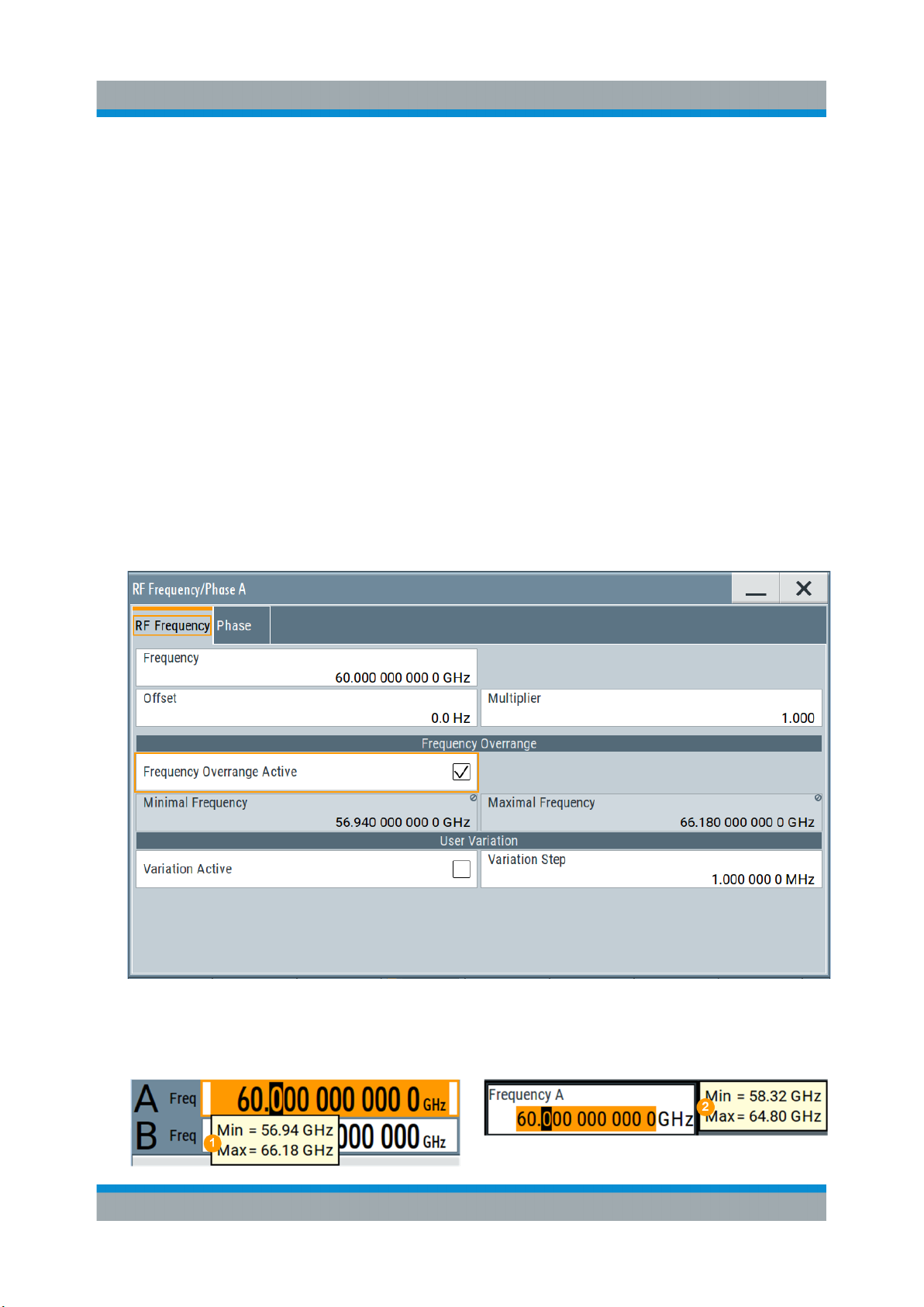
Furthermore, it obtains the calibration data of the R&S SZU. If these calibration data confirm a wider frequency range as given in the data sheet, you can
enable the frequency overrange in the "RF Frequency" setting dialog of the
R&S SMW.
Startup
The R&S SMW adjusts the resulting frequency range also in the status bar.
33Manual 1425.3061.02 ─ 04
Page 34

R&S®SZU100A
Startup
Behavior of the R&S SMW When Working with the R&S SZU
1 = Frequency range with overrange enabled
2 = Frequency range with overrange disabled
Note: The performance in the extended range can deviate from the specified
values given in the data sheet.
●
You can connect and configure the R&S SZUs only in the predetermined
paths, see "Two R&S SZU connected to the R&S SMW" on page 28
The R&S SMW displays error messages, if the connection and the assigned
ports do not match, or, e.g., the connection is interrupted.
●
When disconnected in the "External RF and I/Q" dialog (or via remote control),
the R&S SMW retains the R&S SZU in the list of instruments and at the
assigned output. It presets the R&S SZU and the parameters of the "I/Q Analog Outputs", the "I/Q Modulator" and the "RF" path, and turns off the RF output. Not affected settings remain.
During operation
●
In the status bar, the indicated frequency and level values correspond to the
RF signal at the output of the R&S SZU.
Settings like, e.g. level offset or level limit also affect the RF output of the
R&S SZU.
●
The firmware of the R&S SMW controls the affected I/Q output parameters
automatically, i.e. except of the "I/Q Output Type", the settings are read only.
●
The R&S SMW disables list mode, analog modulations and LO coupling.
At preset
●
If "Preset behavior: Keep connections to external instruments" is enabled, the
R&S SZU remains connected to the R&S SMW, if the USB and I/Q connections still exist physically.
The R&S SMW presets the RF parameters to the R&S SZUs default values
("RF Off", "RF Freq = 60 GHz", "RF Level = 30 dBm").
The "Frequency Overrange" setting is not affected. It is reset only by factory
preset.
●
If "Preset behavior: Keep connections to external instruments" is disabled, the
R&S SMW presets the R&S SZU, cuts the connection and presets to its
default values.
It also resets the "Frequency Overrange".
●
If no R&S SZU is connected, the R&S SMW presets to its default values ("RF
Off", "RF Freq = 1 GHz", "RF Level = 30 dBm").
34Manual 1425.3061.02 ─ 04
Page 35

R&S®SZU100A
Behavior of the R&S SMW When Working with the R&S SZU
At reboot
●
If "Auto connect" is enabled, the R&S SMW establishes the connection automatically, provided the USB connection exists and the R&S SZU is assigned
to an I/Q output
●
If "Auto connect" is disabled, the state remains disconnected, the entry in the
list of external instruments still exists.
At recall
Applies the settings from a saved configuration.
For a proper configuration, load saved configurations that fit to the current
setup.
Do not load a saved configuration of a connected R&S SZU and R&S SMW
in a standalone R&S SMW and vice versa.
Startup
Mismatch between the setup and the loaded configuration leads to wrong
frequency indication in the status bar. The output frequency is correct and
corresponds to the current setup.
In setups with R&S SZU and R&S SMW, always establish the connection
between the two instruments and load a saved configuration with a connected
setup.
35Manual 1425.3061.02 ─ 04
Page 36

R&S®SZU100A
Remote Control of the R&S SZU
8 Remote Control of the R&S SZU
For description of the remote control commands required to connect and configure the connection between the R&S SZU in the R&S SMW, see the www.rohde-
schwarz.com/product/SMW200A/User Manual of the R&S SMW, chapter
"Remote Control Commands > SCONfiguration Subsystem" .
When connected to the R&S SMW, the R&S SZU is remotely controlled with the
same commands as the R&S SMW.
The following remote control commands apply also to the R&S SZU:
●
"SOURce:FREQuency Subsystem"
[:SOURce<hw>]:FREQuency[:CW|FIXed]
Value range of command: 58.32 GHz to 64.8 GHz
●
"SOURce:PHASe Subsystem"
●
"SOURce:POWer Subsystem"
[:SOURce<hw>]:POWer[:LEVel][:IMMediate][:AMPLitude]
Value range of command: -80 dBm to 12 dBm
[:SOURce<hw>]:POWer:ATTenuation
Value range of the command: 0 dB to 50 dB
The ALC remote control commands are queries only.
●
"SOURce:OUTPut Subsystem"
●
"SOURce:CORRection Subsystem"
●
"SENSe, READ, INITiate and SLISt Subsystems"
●
"SOURce:IQ:OUTPut:ANALog Subsystem"
[:SOURce<hw>]:IQ:OUTPut[:ANALog]:TYPE
All other commands in the "SOURce:IQ:OUTPut:ANALog Subsystem" are
queries only.
●
"SOURce:BB:IMPairment Subsystem"
[:SOURce<hw>]:BB:IMPairment:OPTimization:MODE
Analog impairments ([:SOURce<hw>]:IQ:IMPairment:...)
Digital impairments ([:SOURce]:BB:IMPairment:IQOutput<ch>:...)
[:SOURce<hw>]:IQ:STATe
●
All other commands in the "SOURce:IQ Subsystem" are queries only.
●
The commands of the "SOURce:IQ:DPD Subsystem"
36Manual 1425.3061.02 ─ 04
Page 37

R&S®SZU100A
When the R&S SZU is connected to the R&S SMW, the following remote control
commands for the particular RF output are disabled also for the R&S SMW:
●
"Analog Modulation Subsystems"
●
"SOURce:LIST Subsystem"
●
"SOURce:SWEep Subsystem"
●
The commands of the "SOURce:IQ:OUTPut:ENVelope Subsystem"
Remote Control of the R&S SZU
37Manual 1425.3061.02 ─ 04
Page 38

R&S®SZU100A
Glossary: List of Frequently Used Terms and Abbreviations
Glossary: List of Frequently Used Terms and
Abbreviations
D
DUT: Device Under Test
G
Glossary: List of the often used terms and abbreviations
GUI: Graphical User Interface
O
OS: Operating System
OTA: Over The Air
P
PC: Personal Computer, desktop or laptop PC
R
RF: Radio Frequency
S
Serial number: Unique device identification, provided at the rear panel of the
R&S SZU IQ upconverter and required to build the Computer name.
The serial number are the last 6 digits in the string <stock no.>-<serial
number>, e.g. 1425.8563.02-100099
T
Trigger: Internally generated or externally supplied signal which starts signal gen-
eration at a particular point in time.
Trigger event: A trigger event is caused by the received trigger signal or executed manual trigger.
38Manual 1425.3061.02 ─ 04
Page 39

R&S®SZU100A
Glossary: List of Frequently Used Terms and Abbreviations
U
USB: Universal Serial Bus. A standard type of connection for many different kinds
of devices.
W
Warm-up time: Minimum time the device needs to reach operating temperature
and to adjust to the ambient temperature. The R&S SZU requires at least
30 minutes.
39Manual 1425.3061.02 ─ 04
Page 40

R&S®SZU100A
Index
Index
A
About
IQ upconverter ...................................... 8
Adjusting the feet
Preparing for use ................................ 12
B
Brochure ....................................................6
D
Data sheet ................................................. 6
DC power ................................................ 20
Documentation overview ........................... 6
F
Feet ......................................................... 12
G
Getting started ...........................................6
I
Instrument setup ...................................... 11
IQ upconverter
About .................................................... 8
Key features ..........................................8
Welcome ...............................................8
K
Key features
IQ upconverter ...................................... 8
L
LO connection ......................................... 20
LO in ........................................................17
LO out ......................................................17
O
Preparing for use .....................................10
Adjusting the feet ................................ 12
Putting into operation .......................... 11
Unpacking and checking .....................10
Putting into operation
Preparing for use ................................ 11
R
Rear panel ...............................................14
Release notes ........................................... 6
Required equipment ................................ 19
RF connector input .................................. 17
S
Safety instructions ..................................... 6
Starting up ............................................... 20
Status LED .............................................. 16
SZU100A
IQ upconverter ...................................... 8
T
Test port ...................................................13
Test port adapter ..................................... 13
Trigger input/output connector .................17
U
Unpacking and checking
Packaging material ............................. 10
Preparing for use ................................ 10
USB cable ............................................... 20
USB interface .......................................... 17
W
Waveguide flange ....................................13
Welcome
SZU100A .............................................. 8
Online help ................................................ 6
Open source acknowledgment ..................6
OSA ...........................................................6
P
Packaging material ..................................10
Power on ................................................. 20
Power supply connector .......................... 15
40Manual 1425.3061.02 ─ 04
 Loading...