

Page 1

R&S®SMW-K60/-K117
Bluetooth®Enhanced Data Rate,
Bluetooth®5.x
User Manual
(;ÙÒ32)
1175680302
Version 21
Page 2

This document describes the following software options:
●
R&S®SMW-K60 Bluetooth EDR (1413.4239.xx)
●
R&S®SMW-K117 Bluetooth 5.x (1414.3336.xx)
This manual describes firmware version FW 4.80.041.xx and later of the R&S®SMW200A.
© 2020 Rohde & Schwarz GmbH & Co. KG
Mühldorfstr. 15, 81671 München, Germany
Phone: +49 89 41 29 - 0
Email: info@rohde-schwarz.com
Internet: www.rohde-schwarz.com
Subject to change – Data without tolerance limits is not binding.
R&S® is a registered trademark of Rohde & Schwarz GmbH & Co. KG.
The Bluetooth® word mark and logos are owned by Bluetooth SIG, Inc. and any use of such marks by Rohde & Schwarz is under
license.
Trade names are trademarks of the owners.
1175.6803.02 | Version 21 | R&S®SMW-K60/-K117
The following abbreviations are used throughout this manual: R&S®SMW200A is abbreviated as R&S SMW, R&S®WinIQSIM2TM is
abbreviated as R&S WinIQSIM2; the license types 02/03/07/11/13/16/12 are abbreviated as xx.
Page 3

R&S®SMW-K60/-K117
Contents
1 Welcome to the Bluetooth Options...................................................... 7
1.1 Key Features..................................................................................................................7
1.2 Accessing the Bluetooth Dialog.................................................................................. 8
1.3 Documentation Overview............................................................................................. 8
1.3.1 Getting Started Manual................................................................................................... 9
1.3.2 User Manuals and Help...................................................................................................9
1.3.3 Tutorials...........................................................................................................................9
1.3.4 Service Manual............................................................................................................... 9
1.3.5 Instrument Security Procedures......................................................................................9
1.3.6 Printed Safety Instructions............................................................................................ 10
1.3.7 Data Sheets and Brochures.......................................................................................... 10
Contents
1.3.8 Release Notes and Open Source Acknowledgment (OSA).......................................... 10
1.3.9 Application Notes, Application Cards, White Papers, etc..............................................10
1.4 Scope............................................................................................................................11
1.5 Notes on Screenshots................................................................................................ 11
2 About the Bluetooth Options.............................................................. 12
2.1 Required Options........................................................................................................ 12
2.2 About Bluetooth BR/EDR........................................................................................... 12
2.2.1 Bluetooth Packet Types for BR/EDR.............................................................................13
2.2.1.1 ACL Packets................................................................................................................. 13
2.2.1.2 SCO and eSCO Packets...............................................................................................14
2.2.1.3 Link Control Packets for ACL, SCO, eSCO Transport Modes...................................... 15
2.2.2 Bluetooth Transport Modes...........................................................................................16
2.2.3 Packet Structure and Fields.......................................................................................... 16
2.2.3.1 Access Code................................................................................................................. 16
2.2.3.2 Header.......................................................................................................................... 16
2.2.3.3 Payload Format.............................................................................................................17
2.2.4 Bluetooth Modulation Schemes.................................................................................... 19
2.3 About Bluetooth LE.....................................................................................................19
2.3.1 Packet Formats for LE.................................................................................................. 20
2.3.2 Packet Types for LE......................................................................................................22
3User Manual 1175.6803.02 ─ 21
Page 4

R&S®SMW-K60/-K117
2.3.3 Packet Structure and Fields.......................................................................................... 23
2.3.3.1 Advertising Channel Packet Structure.......................................................................... 23
2.3.3.2 Data Channel Packet Structure.....................................................................................26
2.3.4 Modulation Scheme...................................................................................................... 26
2.3.5 Direction Finding........................................................................................................... 27
3 Bluetooth Configuration and Settings............................................... 32
3.1 General Settings..........................................................................................................32
3.2 Dirty Transmitter Test................................................................................................. 35
3.3 Channel Settings - BR/EDR........................................................................................40
3.4 Packet Configuration - BR/EDR................................................................................. 42
3.5 Channel Settings - LE................................................................................................. 49
3.6 Event / Frame Configuration - LE.............................................................................. 54
Contents
3.6.1 Advertising Event / Frame Settings...............................................................................56
3.6.2 Data Event Settings...................................................................................................... 59
3.6.3 Channel Table Settings................................................................................................. 61
3.7 Packet Configuration - LE.......................................................................................... 63
3.7.1 General Packet Configuration....................................................................................... 63
3.7.2 Header Configuration.................................................................................................... 64
3.7.3 Main Payload Configuration Dialog...............................................................................68
3.7.4 Additional Payload Configuration Dialogs..................................................................... 84
3.8 Test Packet Configuration - LE.................................................................................. 88
4 Signal Control and Signal Characteristics........................................ 93
4.1 Filter/Clipping Settings...............................................................................................93
4.1.1 Filter Settings................................................................................................................ 93
4.1.2 Modulation Settings.......................................................................................................95
4.1.3 Clipping Settings........................................................................................................... 97
4.2 Power Ramping Settings............................................................................................98
4.3 Trigger Settings.........................................................................................................100
4.4 Marker Settings......................................................................................................... 105
4.5 Clock Settings........................................................................................................... 107
4.6 Local and Global Connector Settings..................................................................... 108
5 Remote-Control Commands............................................................. 109
4User Manual 1175.6803.02 ─ 21
Page 5

R&S®SMW-K60/-K117
5.1 General Commands.................................................................................................. 110
5.2 Dirty Transmitter Configuration...............................................................................115
5.3 Channel Configuration Commands - BR/EDR........................................................122
5.4 Packet Configuration Commands - BR/EDR.......................................................... 123
5.5 Channel Configuration Commands - LE................................................................. 133
5.6 Event and Frame Configuration Commands - LE.................................................. 138
5.7 Packet Configuration Commands - LE....................................................................148
5.7.1 General Configuration................................................................................................. 154
5.7.2 Header Configuration.................................................................................................. 155
5.7.3 Payload Configuration.................................................................................................158
5.8 Test Packet Configuration Commands - LE............................................................187
5.9 Filter/Clipping Settings.............................................................................................189
5.10 Power Ramping Commands.................................................................................... 195
Contents
5.11 Trigger Commands................................................................................................... 197
5.12 Marker Commands....................................................................................................202
5.13 Clock Commands......................................................................................................206
Glossary: Specifications................................................................... 208
List of commands.............................................................................. 209
Index....................................................................................................215
5User Manual 1175.6803.02 ─ 21
Page 6

R&S®SMW-K60/-K117
Contents
6User Manual 1175.6803.02 ─ 21
Page 7

R&S®SMW-K60/-K117
1 Welcome to the Bluetooth Options
The R&S SMW-K60 is a firmware application that adds functionality to generate signals in accordance with the Bluetooth version 4.2.
Option R&S SMW-K117 adds support for Bluetooth LE signals according to the core
specification v 5.1 for Bluetooth wireless technology. This option is an extension of
R&S SMW-K60.
This user manual contains a description of the functionality that the application provides, including remote control operation.
All functions not discussed in this manual are the same as in the base unit and are
described in the R&S SMW user manual. The latest version is available at:
www.rohde-schwarz.com/manual/SMW200A
Installation
You can find detailed installation instructions in the delivery of the option or in the
R&S SMW service manual.
Welcome to the Bluetooth Options
Key Features
1.1 Key Features
Option R&S SMW-K60 provides Bluetooth signals for basic rate (BR) and enhanced
data rate (EDR) burst types. In addition, it provides also low energy (LE) signals limited
to LE 1 Msymbol/s physical layer.
The following BR and EDR features are supported within R&S SMW-K60:
●
Support for three transport modes, the ACL+EDR, SCO, eSCO+EDR transport
modes.
●
Support of all packet types for both the basic rate and the enhanced data rate
modes.
●
Generation of signals with up to 5238 frames sequence length.
●
Configuration of the packet contents with a convenient packet editor or all data
packets, both with optional data whitening.
●
Generation of signals in accordance to the "Dirty Transmitter Test" specification for
both, the basic and enhanced data rates. The test enables you to change the start
phase, the frequency drift rate and the frequency drift deviation.
●
Power ramp control with possibilities to choose ramp time, rise and fall offset
●
Configuration of the clipping, filter and modulation settings
The following LE features are supported within R&S SMW-K60:
●
Support for two channel types, the "Advertising" and "Data" channel types.
●
Support of all Bluetooth packet types for LE 1 Msymbol/s physical layer (LE 1M
PHY).
●
Convenient packet editor for all supported packet types including optional data
whitening.
7User Manual 1175.6803.02 ─ 21
Page 8

R&S®SMW-K60/-K117
●
●
●
●
The following LE features are supported within R&S SMW-K117:
●
●
●
●
●
●
●
Welcome to the Bluetooth Options
Documentation Overview
Dirty transmitter test, compliant to the RF test specification with options to change
start phase, frequency drift rate and frequency drift deviation.
Support of CRC corruption for every 2nd packet
Power ramp control with configurable ramp time, rise and fall offsets.
Clipping, filter and modulation settings supported.
Support for two channel types, the "Advertising" and "Data" channel types.
Support of all Bluetooth packet types for uncoded LE 2 Msymbol/s physical layer
(LE 2M PHY)
Support of all Bluetooth packet types for LE coded 1 Msymbol/s physical layer (LE
coded PHY)
Support of CRC corruption for every 2nd packet
Convenient packet editor for all supported packet types including optional data
whitening.
Dirty transmitter test, compliant to the RF test specification with options to change
start phase, frequency drift rate, frequency drift deviation, and modulation index
mode.
Support of Bluetooth Direction Finding using Constant Tone Extension methods
Angle of Arrival or Angle of Departure
1.2 Accessing the Bluetooth Dialog
To open the dialog with Bluetooth settings
► In the block diagram of the R&S SMW, select "Baseband > Bluetooth".
A dialog box opens that displays the provided general settings.
The signal generation is not started immediately. To start signal generation with the
default settings, select "State > On".
1.3 Documentation Overview
This section provides an overview of the R&S SMW user documentation. Unless specified otherwise, you find the documents on the R&S SMW product page at:
www.rohde-schwarz.com/manual/smw200a
8User Manual 1175.6803.02 ─ 21
Page 9

R&S®SMW-K60/-K117
1.3.1 Getting Started Manual
Introduces the R&S SMW and describes how to set up and start working with the product. Includes basic operations, typical measurement examples, and general information, e.g. safety instructions, etc. A printed version is delivered with the instrument.
1.3.2 User Manuals and Help
Separate manuals for the base unit and the software options are provided for download:
●
●
Welcome to the Bluetooth Options
Documentation Overview
Base unit manual
Contains the description of all instrument modes and functions. It also provides an
introduction to remote control, a complete description of the remote control commands with programming examples, and information on maintenance, instrument
interfaces and error messages. Includes the contents of the getting started manual.
Software option manual
Contains the description of the specific functions of an option. Basic information on
operating the R&S SMW is not included.
The contents of the user manuals are available as help in the R&S SMW. The help
offers quick, context-sensitive access to the complete information for the base unit and
the software options.
All user manuals are also available for download or for immediate display on the Internet.
1.3.3 Tutorials
The R&S SMW provides interactive examples and demonstrations on operating the
instrument in form of tutorials. A set of tutorials is available directly on the instrument.
1.3.4 Service Manual
Describes the performance test for checking compliance with rated specifications, firmware update, troubleshooting, adjustments, installing options and maintenance.
The service manual is available for registered users on the global Rohde & Schwarz
information system (GLORIS):
https://gloris.rohde-schwarz.com
1.3.5 Instrument Security Procedures
Deals with security issues when working with the R&S SMW in secure areas. It is available for download on the Internet.
9User Manual 1175.6803.02 ─ 21
Page 10

R&S®SMW-K60/-K117
1.3.6 Printed Safety Instructions
Provides safety information in many languages. The printed document is delivered with
the product.
1.3.7 Data Sheets and Brochures
The data sheet contains the technical specifications of the R&S SMW. It also lists the
options and their order numbers and optional accessories.
The brochure provides an overview of the instrument and deals with the specific characteristics.
See www.rohde-schwarz.com/brochure-datasheet/smw200a
1.3.8 Release Notes and Open Source Acknowledgment (OSA)
The release notes list new features, improvements and known issues of the current
firmware version, and describe the firmware installation.
Welcome to the Bluetooth Options
Documentation Overview
The open-source acknowledgment document provides verbatim license texts of the
used open source software.
See www.rohde-schwarz.com/firmware/smw200a
1.3.9 Application Notes, Application Cards, White Papers, etc.
These documents deal with special applications or background information on particular topics.
See www.rohde-schwarz.com/application/smw200a and www.rohde-schwarz.com/
manual/smw200a
10User Manual 1175.6803.02 ─ 21
Page 11

R&S®SMW-K60/-K117
1.4 Scope
Tasks (in manual or remote operation) that are also performed in the base unit in the
same way are not described here.
In particular, it includes:
●
●
●
●
For a description of such tasks, see the R&S SMW user manual.
Welcome to the Bluetooth Options
Notes on Screenshots
Managing settings and data lists, like saving and loading settings, creating and
accessing data lists, or accessing files in a particular directory.
Information on regular trigger, marker and clock signals and filter settings, if appropriate.
General instrument configuration, such as checking the system configuration, configuring networks and remote operation
Using the common status registers
1.5 Notes on Screenshots
When describing the functions of the product, we use sample screenshots. These
screenshots are meant to illustrate as many as possible of the provided functions and
possible interdependencies between parameters. The shown values may not represent
realistic usage scenarios.
The screenshots usually show a fully equipped product, that is: with all options installed. Thus, some functions shown in the screenshots may not be available in your particular product configuration.
11User Manual 1175.6803.02 ─ 21
Page 12

R&S®SMW-K60/-K117
2 About the Bluetooth Options
The R&S SMW provides you with the ability to generate signals in accordance with the
core specification 5.1 for Bluetooth wireless technology.
This section lists required options and provides background information on basic terms
and principles used in Bluetooth technology.
2.1 Required Options
The basic equipment layout for generating Bluetooth signals includes the:
●
●
●
●
●
About the Bluetooth Options
About Bluetooth BR/EDR
Standard Baseband Generator (R&S SMW-B10)
Baseband main module (R&S SMW-B13/-B13T
Frequency option (e.g. R&S SMW-B1003)
Option Bluetooth EDR (R&S SMW-K60) per signal path
Option Bluetooth 5.x (R&S SMW-K117) per signal path
You can generate signals via play-back of waveform files at the signal generator. To
create the waveform file using R&S WinIQSIM2, you do not need a specific option.
To play back the waveform file at the signal generator, you have two options:
●
Install the R&S WinIQSIM2 option of the digital standard, e.g. R&S SMW-K255 for
playing LTE waveforms
●
If supported, install the real-time option of the digital standard, e.g. R&S SMW-K55
for playing LTE waveforms
For more information, see data sheet.
2.2 About Bluetooth BR/EDR
The frequency band defined for Bluetooth devices is the unlicensed 2.4 GHz Industrial,
Scientific and Medical (ISM) frequency band.
Table 2-1: Operating band
Regulatory range RF channels k and center frequencies f
2400.0 MHz to 2483.5 MHz k = 0 to 78, f = k * 1 MHz + 2402 MHz
Two modulation modes are used for Bluetooth: the mandatory basic rate (BR) and the
optional enhanced data rate (EDR). The BR mode uses binary FM modulation and provides a data rate of 1 Mbps. The EDR mode uses two types of PSK modulation, the
π/4-DQPSK or 8DPSK, and achieves data rates of 2 Mbps and 3 Mbps, respectively.
All modulations schemes have the symbol rate equal to 1 Msymbol/s.
A time division duplex (TDD) scheme for duplex transmission is defined for both
modes.
12User Manual 1175.6803.02 ─ 21
Page 13
R&S®SMW-K60/-K117
The following sections describe signal characteristics in detail:
● Bluetooth Packet Types for BR/EDR.......................................................................13
● Bluetooth Transport Modes.....................................................................................16
● Packet Structure and Fields....................................................................................16
● Bluetooth Modulation Schemes.............................................................................. 19
2.2.1 Bluetooth Packet Types for BR/EDR
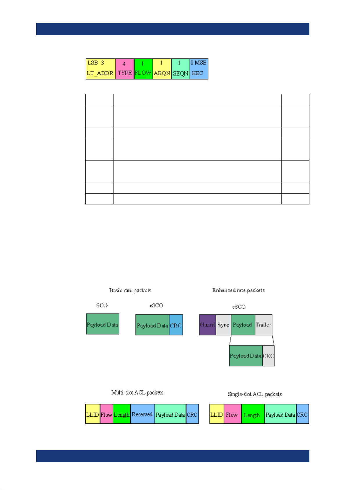
2.2.1.1 ACL Packets
The ACL packets are used for asymmetric links and they contain user data or control
data. The table and the figures below give an overview of the ACL packets and their
structure.
Table 2-2: ACL packet - basic rate
About the Bluetooth Options
About Bluetooth BR/EDR
Type Payload
Header (bytes)
DM1 1 0-17 2/3
DH1
DM3
DH3
DM5
DH5
AUX1 1 0-29
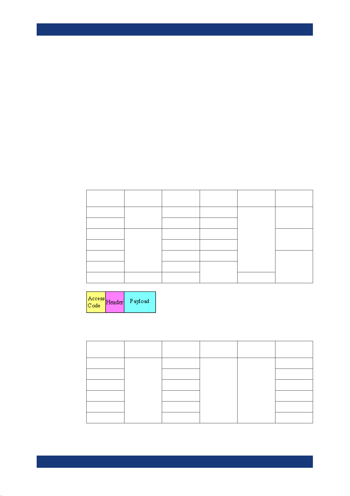
Figure 2-1: Packet structure of ACL packets - basic rate
Table 2-3: ACL packets - enhanced rate
Type Payload
2-DH1
2
Header (bytes)
User Payload
(bytes)
0-27 no
0-121 2/3
0-183 no
0-224 2/3
0-339 no
User Payload
(bytes)
0-54
FEC CRC Slot number
FEC CRC Slot number
Yes, 16-bit 3
no
1
5
1
2-DH3
2-DH5
3-DH1
3-DH3
2-DH5
2
0-367
0-679
0-83
0-552
0-1021
no Yes, 16-bit
3
5
1
3
5
13User Manual 1175.6803.02 ─ 21
Page 14
R&S®SMW-K60/-K117
Figure 2-2: Packet structure of ACL packets - enhanced data rate
2.2.1.2 SCO and eSCO Packets
The SCO and eSCO packets are used for symmetric links. The SCO packets are used
for 64 kb/s speech transmission and for transparent synchronous data. The eSCO
packets are also used for 64kb/s speech transmission and transparent data at 64 kb/s
but also at other rates.
The tables and the figures below give an overview of the SCO and eSCO packets and
their structure.
Table 2-4: SCO packets
About the Bluetooth Options
About Bluetooth BR/EDR
Type Payload
Header (bytes)
HV1
HV2
HV3
DV 1 (data only) 10+(0-9) 2/3 (data only) Yes, 16-bit
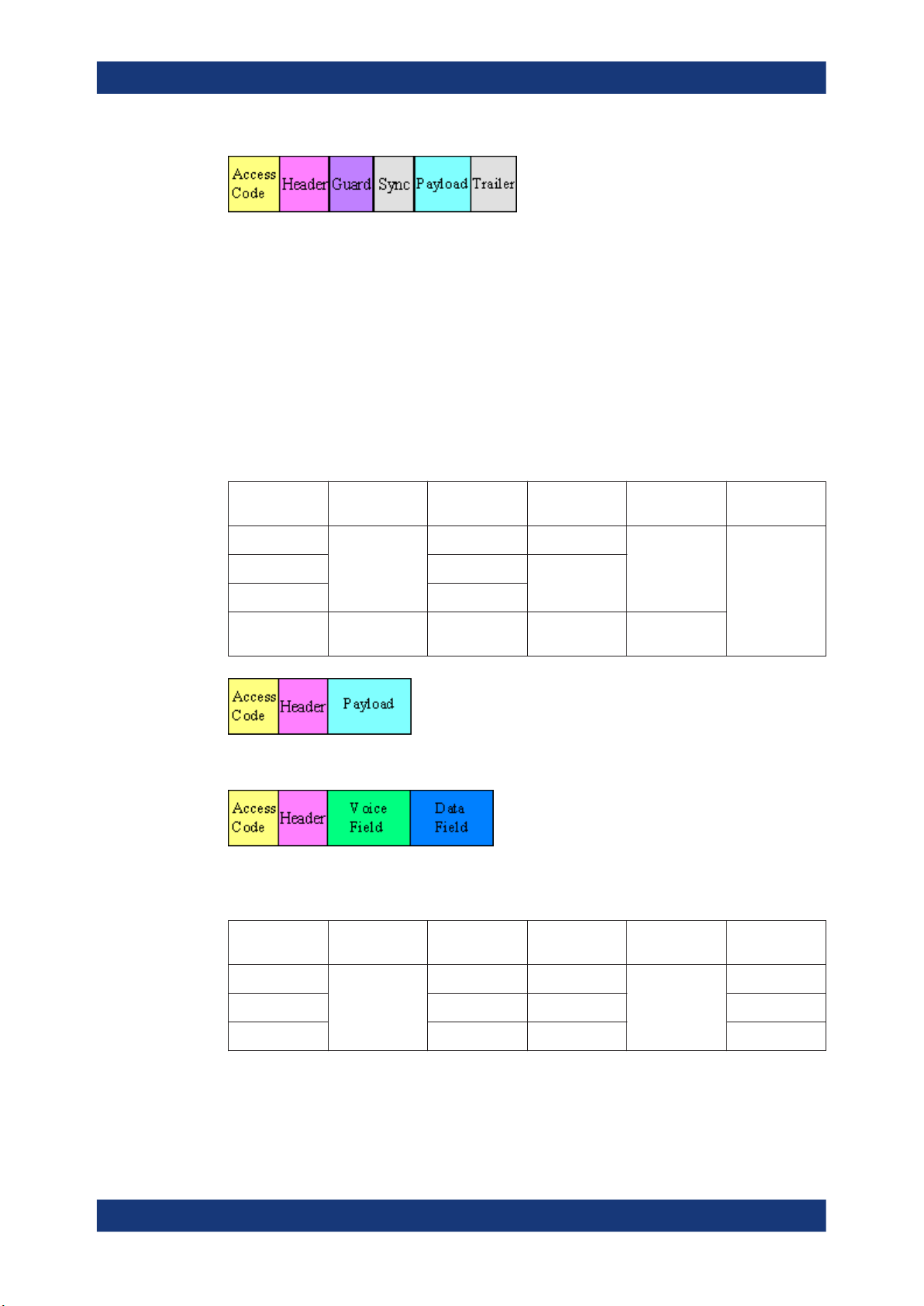
Figure 2-3: Packet structure SCO packets
Figure 2-4: Packet structure SCO packets (data only)
Table 2-5: eSCO packets - basic rate
Type Payload
n.a.
Header (bytes)
User Payload
(bytes)
10 1/3
20
30
User Payload
(bytes)
FEC CRC Slot number
2/3
FEC CRC Slot number
no
(data only)
n.a.
EV3
EV4
EV5
n.a.
1-30 no
1-120 2/3
1-180 no
Yes, 16-bit
(Data only)
1
3
3
14User Manual 1175.6803.02 ─ 21
Page 15
R&S®SMW-K60/-K117
Figure 2-5: Packet structure eSCO packets - basic rate
Table 2-6: eSCO packets - basic rate
About the Bluetooth Options
About Bluetooth BR/EDR
Type Payload
Header (bytes)
2-EV3
2-EV5
3-EV3
3-EV5
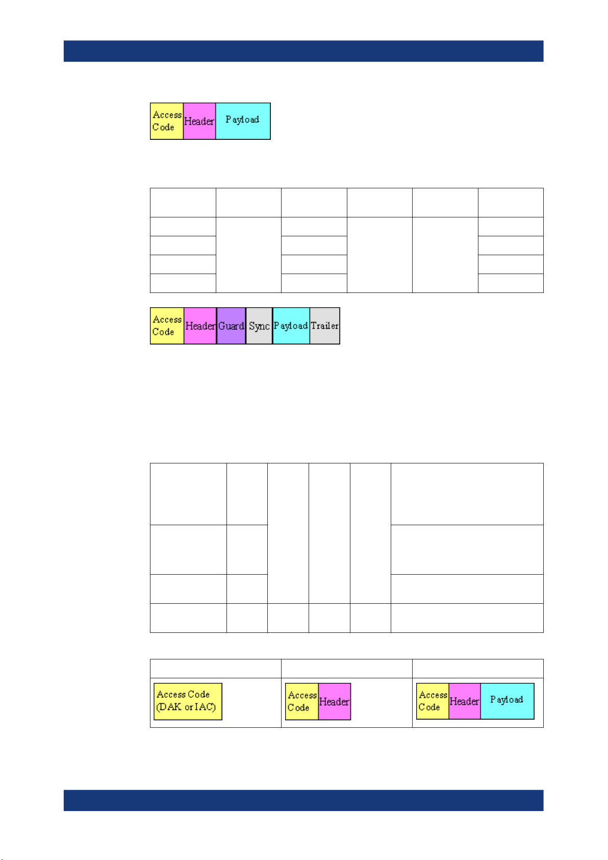
Figure 2-6: Packet structure eSCO packets - enhanced data rate
n.a.
User Payload
(bytes)
1-60
1-360
1-90
1-540
FEC CRC Slot number
no Yes,
16-bit
2.2.1.3 Link Control Packets for ACL, SCO, eSCO Transport Modes
There are some common kinds of packet types. An overview of these packet types is
given in the table below.
Table 2-7: Common link control packets
Transport modes Type Payload
Header
(bytes)
FEC CRC Application
1
3
1
3
SCO, eSCO, ACL ID
SCO, eSCO, ACL NULL
SCO, eSCO, ACL POLL
SCO, ACL FHS 18 2/3 Yes Page master response, inquiry
Table 2-8: Common link control packets: packet structure
Packet Type ID Packet Types NULL and PULL Packet Types FHS
n.a. n.a. n.a.
Paging, inquiry, response
Carries Link information to the source,
e.g. about successfully received signal
(ARQN) or the state of the receiving
buffer (FLOW)
Similar to NULL packet, used by master
to poll the slaves, must be confirmed
response, in roll switch
15User Manual 1175.6803.02 ─ 21
Page 16
R&S®SMW-K60/-K117
2.2.2 Bluetooth Transport Modes
There are three different transport modes defined in the Bluetooth core specification,
each of them with special applications:
●
●
●
There are some common transmitted packets used by all transport modes and some
specific packets defined for each transport mode.
2.2.3 Packet Structure and Fields
About the Bluetooth Options
About Bluetooth BR/EDR
Synchronous connection-oriented (SCO)
The SCO transport mode is used for a symmetric point-to-point link establishment
between a master and a specific slave in the piconet.
Extended synchronous connection-oriented (eSCO)
The eSCO transport mode is used for a symmetric or asymmetric, point-to-point
link establishment between the master and a specific slave.
Asynchronous connection less (ACL)
The ACL transport mode is used for a point-to-multipoint link establishment
between the master and all slaves participating on the piconet.
Almost all Bluetooth transmitted packets have standard format and consist of the
access code, the header and the payload with useful information. The exceptions are
the ID packet which consists of the access code only and NULL and POLL packets
which carry only the access code and the header.
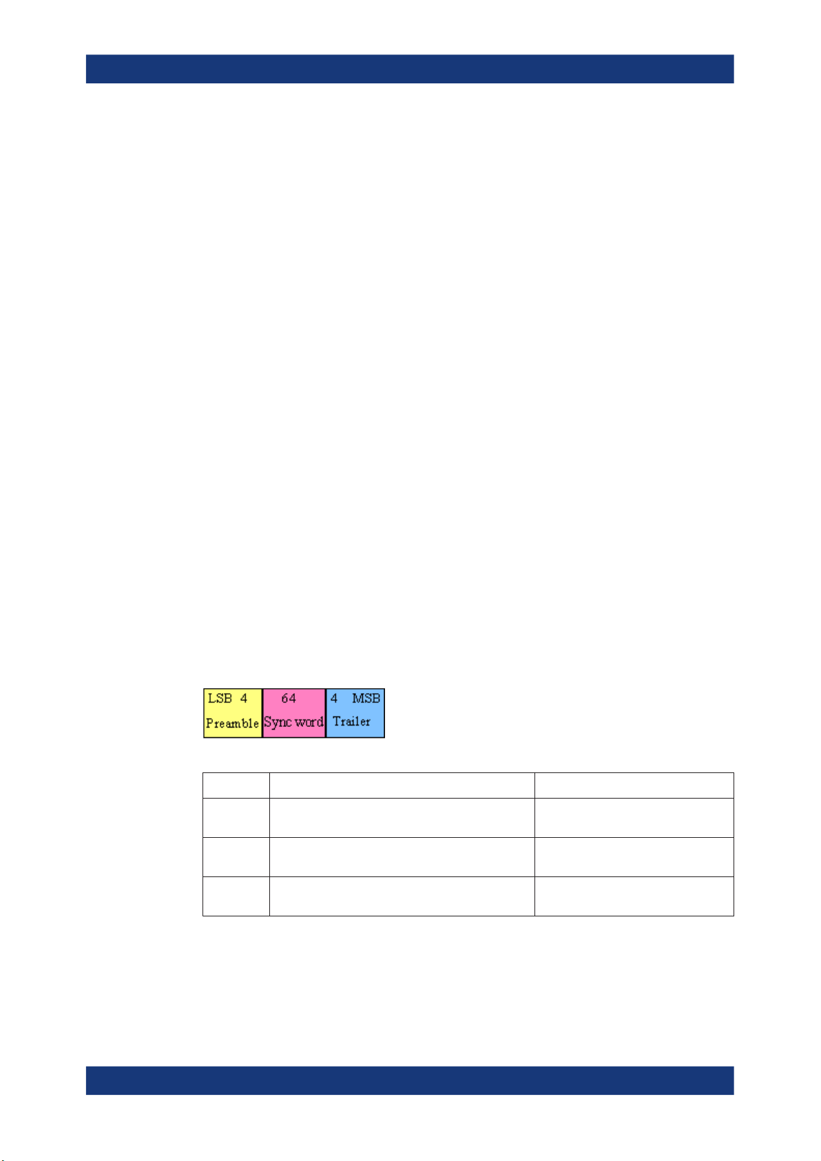
2.2.3.1 Access Code
The access code is used for synchronization, DC offset compensation and identification. The fields of the access code are shown in the figure below and their meaning is
explained in the table below.
Table 2-9: The access code fields
Field Description Packets
Preamble A fixed zero-one pattern of 4 symbols, used to facili-
tate DC compensation
Sync word A 64-bit code word derived from a 24-bit address,
improves timing acquisition
Trailer A fixed zero-one pattern of four symbols, extended
DC compensation
All packets
All packets
All packets, except ID
2.2.3.2 Header
The header contains link control information. The fields of the header are shown in the
figure and their meaning is explained in the table below.
16User Manual 1175.6803.02 ─ 21
Page 17
R&S®SMW-K60/-K117
Table 2-10: The header fields
Field Description Packets
About the Bluetooth Options
About Bluetooth BR/EDR
LT_ADDR Logical transport address, indicates the destination slave for a packet in a mas-
ter-to-slave transmission slot and the source slave for a slave-to-master transmission slot
TYPE Type code, specifies which packet type is used
FLOW Flow control, used for flow control of packets over the ACL logical transport.
When the RX buffer in the recipient is full, a STOP indication must be returned.
When the RX buffer can accept data, a "Go" indication must be returned.
ARQN Automatic repeat request number, acknowledgement indication, used to inform
the source of a successful transfer of payload data with CRC can be positive
acknowledged ACK or negative acknowledged NAK,
SEQN Sequential numbering scheme to order the data packet stream
HEC Header-error-check to check the header integrity
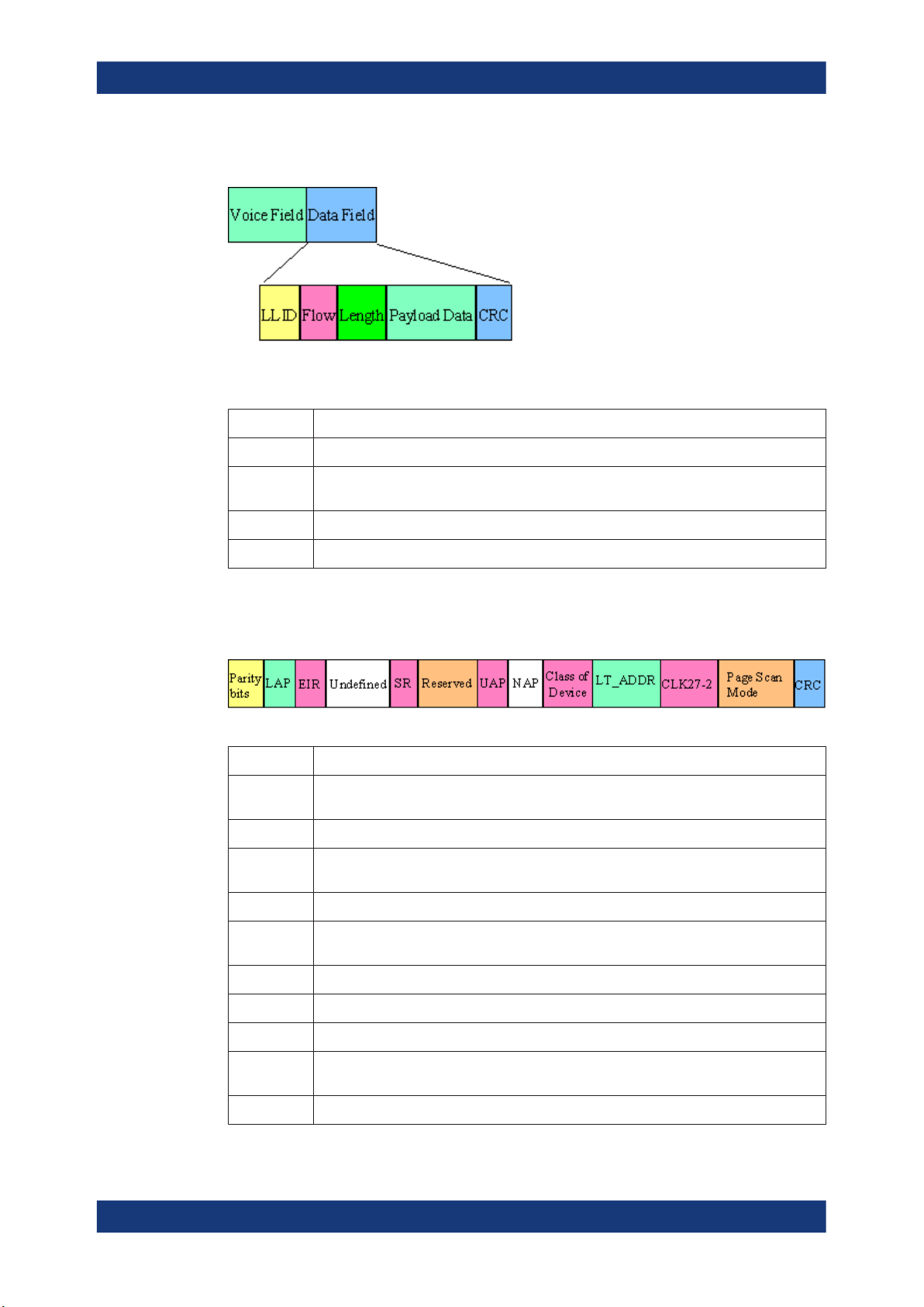
2.2.3.3 Payload Format
The payload structure depends on the type of the data field and the data rate. Two
fields are defined in the payload: the synchronous data field and the asynchronous
data field. The ACL packets only have the asynchronous data field and the SCO and
eSCO packets only have the synchronous data field. The exception is DV of SCO
transport mode which has both data fields, synchronous and asynchronous.
All packets,
except ID
Synchronous data fields
Asynchronous data fields
17User Manual 1175.6803.02 ─ 21
Page 18
R&S®SMW-K60/-K117
Synchronous and asynchronous data fields
The meaning of some payload fields is given in the table below.
Table 2-11: The payload fields
Field Description
CRC The cyclic redundancy error check
Guard, sync The guard time and synchronization sequence, used for physical layer change of modula-
LLID The logical link identifier, specifies the logical link
About the Bluetooth Options
About Bluetooth BR/EDR
tion scheme
Flow Field which controls the flow on the logical channels
The payload format and content of the FHS packet are different from other packets.
The fields of the FHS packet are shown in the figure below and their meaning is
explained in the table below.
Table 2-12: The payload fields for the FHS packet
Field Description
Parity bits Form the first part of the sync word of the access code of the device that sends the FHS
packet
LAP Contains the lower address part of the device that sends the FHS packet
EIR An extended inquiry response, provides miscellaneous information during the inquiry
response procedure
Undefined Reserved for future use and must be set to zero
SR The scan repetition field, indicates the interval between two consecutive page scan win-
dows
Reserved Must be set to 10
UAP Contains the upper address part of the device that sends the FHS packet
NAP Contains the non–significant address part of the device that sends the FHS packet
Class of
device
LT_ADDR Contains the logical transport address
Contains the class of device of the device that sends the FHS packet. This field is defined
in Bluetooth assigned numbers.
18User Manual 1175.6803.02 ─ 21
Page 19

R&S®SMW-K60/-K117
Field Description
CLK27-2 Contains the value of the native clock of the device that sends the FHS packet, sampled at
About the Bluetooth Options
About Bluetooth LE
the beginning of the transmission of the access code of this FHS packet
Page scan
mode
Indicates which scan mode is used by default by the sender of the FHS packet
2.2.4 Bluetooth Modulation Schemes
The modulation used for the basic data rate packets is GFSK (Gaussian Frequency
Shift Keying) with a bandwidth bit period product BT = 0.5. The modulation index is
between 0.28 and 0.35.
The modulation scheme used for enhanced data rate packets changes within the
packet. The access code and packet header have a GFSK modulation scheme and are
transmitted with the basic rate 1Mbps. The subsequent synchronization sequence,
payload and trailer sequence have a PSK type of modulation and are transmitted with
a data rate of 2 Mbps or optionally 3 Mbps.
The PSK modulation, namely π/4 rotated differential encoded quaternary phase shift
keying (π/4–DQPSK) is defined for the 2 Mbps transmission.
The PSK modulation, namely differential encoded 8-ary phase shift keying (8DPSK), is
defined for the 3Mbps transmission.
The modulation types and corresponding packet types are given in the table below.
Table 2-13: The modulation types and corresponding packet types
Modulation type Packet types
GFSK ID, NULL, POLL, FHS, DM1, DH1, DM3, DH3, DM5, DH5, AUX1, HV1, HV2, HV3,
DV, EV3, EV4, EV5
GFSK + π/4-DQPSK 2-DH1, 2-DH3, 2-DH5, 2-EV3, 2-EV5
GFSK + 8DPSK 3-DH1, 3-DH3, 3-DH5, 3-EV3, 3-EV5
2.3 About Bluetooth LE
The R&S SMW provides you with the ability to generate signals in accordance with the
Low Energy (LE) specification for Bluetooth wireless technology.
Bluetooth LE provides data transfer from low-power devices running on the smallest of
batteries to a larger device, such as a PC, a mobile phone, or a PDA. Bluetooth LE
establishes a connection, e.g. to a wristwatch, a heart rate sensor, or a data transfer
from a digital camera. The generated packets do not support audio content.
A time division duplex (TDD) scheme for duplex transmission is defined. The frequency
band defined for Bluetooth devices is the unlicensed 2.4 GHz "Industrial, Scientific and
Medical" (ISM) frequency band.
19User Manual 1175.6803.02 ─ 21
Page 20
R&S®SMW-K60/-K117
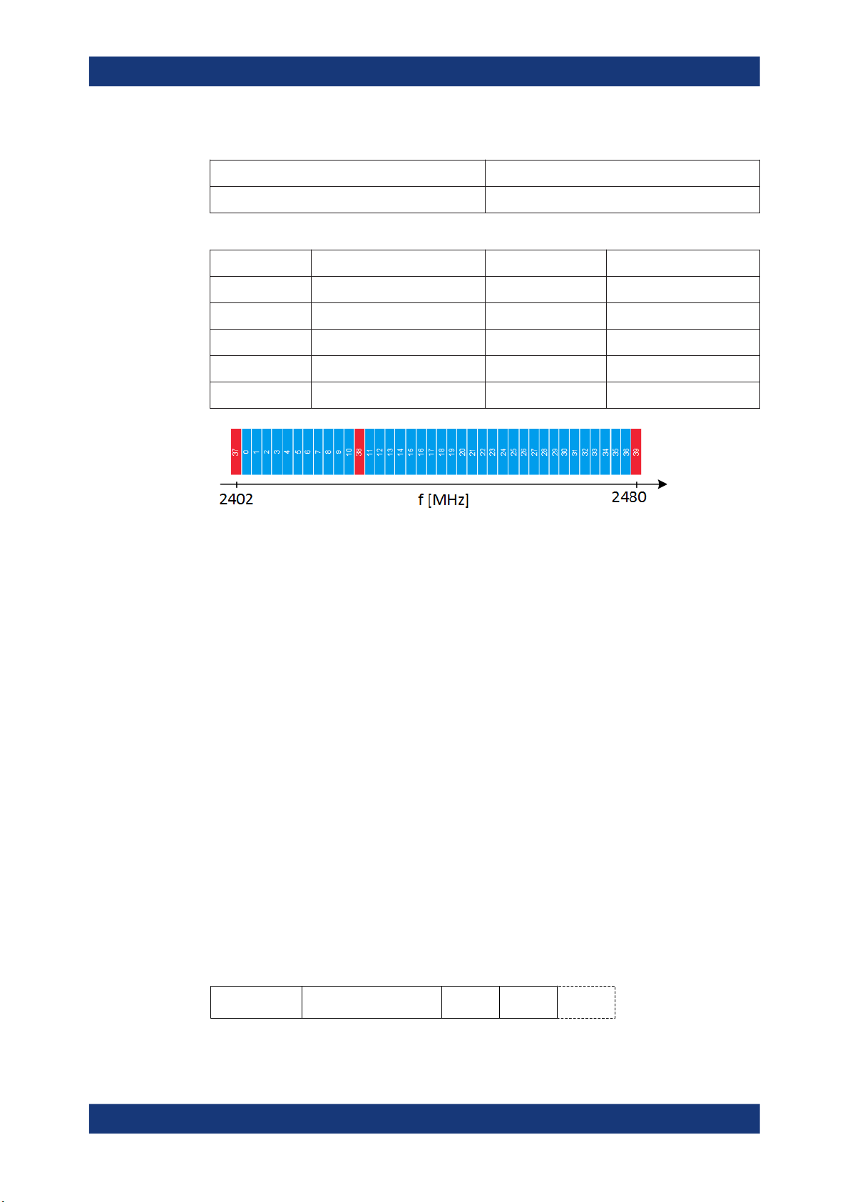
Table 2-14: Operating band
Regulatory range RF channels k and center frequencies f
2400.0 MHz to 2483.5 MHz k = 0 to 39, f = k * 2 MHz + 2402 MHz
Table 2-15: Channel index
RF channel RF center frequency in MHz Data channel index Advertising channel index
0 2402 - 37
1 to 11 2404 to 2424 0 to 10 -
12 2426 - 38
13 to 38 2428 to 2478 11 to 36 -
39 2480 - 39
About the Bluetooth Options
About Bluetooth LE
Figure 2-7: RF channels
red = advertising channels (primary)
blue = data channels and secondary advertising channels
The core specification of Bluetooth wireless technology defines the limits of output
power level at the maximum power setting. The minimum output power is limited to -20
dBm. The maximum output power for LE is limited to 10 dBm.
The maximum output power for LE is limited to 20 dBm.
The following sections describe signal characteristics in detail:
● Packet Formats for LE............................................................................................ 20
● Packet Types for LE................................................................................................22
● Packet Structure and Fields....................................................................................23
● Modulation Scheme................................................................................................ 26
● Direction Finding..................................................................................................... 27
2.3.1 Packet Formats for LE
Packet formats for LE uncoded PHY
The following packet format is defined for the LE uncoded PHYs and is used for both
advertising channel packets and data channel packets.
Figure 2-8: LE uncoded PHY packet format
CTEPreamble Access Address PDU CRC
20User Manual 1175.6803.02 ─ 21
Page 21

R&S®SMW-K60/-K117
Each packet consists of four mandatory fields: preamble, access address, PDU, and
CRC. For Bluetooth Direction Finding, the optional field Constant Tone Extension
(CTE) is added at the end.
Table 2-16: Packet format for LE uncoded PHY
Physical layer Preamble Access address PDU CRC CTE
LE 1 Msymbol/s 1 octet 4 octets 2 to 257 octets 3 octets 16 µs to 160 µs
LE 2 Msymbol/s 2 octets 4 octets 2 to 257 octets 3 octets 16 µs to 160 µs
The preamble is transmitted first, followed by the access address, followed by the PDU
followed by the CRC and optionally followed by CTE. The entire packet is transmitted
at the same symbol rate. Option R&S SMW-K60 supports LE uncoded 1 Msymbol/s
(LE 1M) physical layer (PHY).
Option R&S SMW-K117 supports optional modulation scheme LE uncoded 2
Msymbol/s (LE 2M) PHY.
Packets take between 44 µs and 2120 µs to transmit. The period extends by an additional 16 µs to 160 µs, if CTE is active.
About the Bluetooth Options
About Bluetooth LE
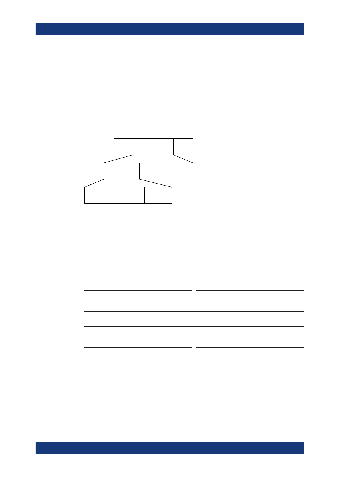
Packet formats for LE coded PHY
The following packet format is defined for the LE coded PHY and is used for both
advertising channel packets and data channel packets.
S = 8 coding S = 2 or 8
Preamble
Access address CI PDUTERM1 TERM2CRC
FEC block 1 FEC block 2
Figure 2-9: LE coded PHY packet format
Each packet consists of the preamble, FEC block 1, and FEC block 2. The preamble is
not coded. The FEC block 1 consists of three fields: access address, coding indicator
(CI), and TERM1. These fields use the S=8 coding scheme. The CI field determines
which coding scheme is used for FEC block 2. The FEC block 2 consists of three
fields: PDU, CRC, and TERM2. These fields use either the S=2 or S=8 coding scheme,
depending on the value of the CI field.
The entire packet is transmitted with 1 Msymbol/s modulation. The following table captures the size and duration of the data packet fields.
Table 2-17: Packet format for LE coded PHY
Preamble
Access
address
CI TERM1 PDU CRC TERM2
Number of uncoded bits 80 32 2 3 16 - 2056 24 3
Duration in µs for S=8 coding 80 256 16 24 128 - 16448 192 24
Duration in µs for S=2 coding 80 256 16 24 32 - 4112 48 6
21User Manual 1175.6803.02 ─ 21
Page 22
R&S®SMW-K60/-K117
Packets take between 462 and 17040 μs to transmit.
2.3.2 Packet Types for LE
Test packet types
The test packet PDU is subdivided into a PDU header and the payload field. The PDU
header indicates the payload content type and the payload length expresses in octets.
RFU field means reserved for future use.
LSB
About the Bluetooth Options
About Bluetooth LE
PDU
MSB
Header
2 octets
PDU type
4 bits
RFU
4 bits
Payload
0-255 octets
Length
8 bits
LE test packets are described in the "Air Interface Packets" section of core specification for Bluetooth wireless technology, volume 6, part B.
Advertising channel packet types
The advertising channel PDU has a 16-bit header and a variable size payload. The
header fields of the advertising channel PDU are as shown in "Header" on page 23.
Table 2-18: Advertising packet types:
ADV_IND
ADV_DIRECT_IND SCAN_RSP
ADV_NONCONN_IND CONNECT_IND
ADV_SCAN_IND
Table 2-19: Additional advertising packet types within R&S SMW-K117:
ADV_EXT_IND
SCAN_REQ
AUX_SCAN_REQ
AUX_ADV_IND AUX_SCAN_RSP
AUX_CHAIN_IND AUX_CONNECT_REQ
AUX_SYNC_IND AUX_CONNECT_RSP
Data channel packet types
The data channel PDU has a 16-bit header, a variable size payload, and can include a
message integrity check (MIC) field as shown in "Header" on page 26.
The MIC field is not included in an unencrypted link layer (LL) connection, or in an
encrypted LL connection with a data channel PDU with a zero length payload. The MIC
22User Manual 1175.6803.02 ─ 21
Page 23

R&S®SMW-K60/-K117
field is included in an encrypted LL connection, with a data channel PDU with a nonzero length payload. The MIC calculation is specified in the section 1 of core specification for Bluetooth wireless technology, volume 6, part E.
Besides the data packet type, instrument supports the following CONTROL_DATA
packet types.
Table 2-20: Control data packet types
About the Bluetooth Options
About Bluetooth LE
Opcode CONTROL_DATA
0x00 LL_CONNECTION_UPDATE_IND
0x01 LL_CHANNEL_MAP_IND
0x02 LL_TERMINATE_IND
0x03 LL_ENC_REQ
0x04 LL_ENC_RSP
0x05 LL_START_ENC_REQ
0x06 LL_START_ENC_RSP
Table 2-21: Additional control data packet types within R&S SMW-K117:
Opcode CONTROL_DATA
0x0E LL_SLAVE_FEAT_REQ
0x0F LL_CONNECTION_PARAM_REQ
0x10 LL_CONNECTION_PARAM_RSP
0x11 LL_REJECT_EXT_IND
0x12 LL_PING_REQ
0x13 LL_PING_RSP
Opcode CONTROL_DATA
0x07 LL_UNKNOWN_RSP
0x08 LL_FEATURE_REQ
0x09 LL_FEATURE_RSP
0x0A LL_PAUSE_ENC_REQ
0x0B LL_PAUSE_ENC_RSP
0x0C LL_VERSION_IND
0x0D LL_REJECT_IND
Opcode CONTROL_DATA
0x14 LL_LENGTH_REQ
0x15 LL_LENGTH__RSP
0x16 LL_PHY_REQ
0x17 LL_PHY_RSP
0x18 LL_PHY UPDATE_IND
0x19 LL_MIN_USED_CHANNELS_IND
2.3.3 Packet Structure and Fields
2.3.3.1 Advertising Channel Packet Structure
Header
LSB
Header
2 octets
PDU type
4 bits
RFU
1 bit
ChSel
1bit
TxAdd
1 bit
PDU
Payload
1-255 octets
RxAdd
1 bit
MSB
Length
8 bits
23User Manual 1175.6803.02 ─ 21
Page 24

R&S®SMW-K60/-K117
●
Table 2-22: PDU type vs. PHYs
About the Bluetooth Options
About Bluetooth LE
The possible PDU types, indicated in the header of advertising channel PDU, are
listed in the previous tables, see Table 2-18.
The following table shows which channels are supported by which PHYs.
PDU
type
0000b ADV_IND Primary advertising x - -
0001b ADV_DIRECT_IND Primary advertising x - -
0010b ADV_NONCONN_IND Primary advertising x - -
0011b SCAN_REQ Primary advertising x - -
0100b SCAN_RSP Primary advertising x - -
0101b CONNECT_IND Primary advertising x - -
0110b ADV_SCAN_IND Primary advertising x - -
0111b ADV_EXT_IND Primary advertising x - x
PDU name Channel Permitted PHY
LE 1M LE 2M LE
AUX_SCAN_REQ Secondary advertising x x x
AUX_CONNECT_REQ Secondary advertising x x x
AUX_ADV_IND Secondary advertising x x x
AUX_SCAN_RSP Secondary advertising x x x
AUX_SYNC_IND Secondary advertising x x x
AUX_CHAIN_IND Secondary advertising x x x
coded
1000b AUX_CONNECT_RSP Secondary advertising x x x
Others Reserved for future use
x marks supported PHYs
●
The ChSel, TxAdd and RxAdd fields contain information specific to the PDU type.
If the ChSel, TxAdd or RxAdd fields are not defined as used in a given PDU then
they are considered Reserved for Future Use.
●
The Length field indicates the payload field length in octets.
Payload
The advertising channel PDU types can be divided into the following three groups.
24User Manual 1175.6803.02 ─ 21
Page 25

R&S®SMW-K60/-K117
Table 2-23: Advertising channel PDU types
About the Bluetooth Options
About Bluetooth LE
Advertising
PDUs
Scanning PDUs SCAN_REQ, SCAN_RSP
Initiating PDUs CONNECT_IND
ADV_IND, ADV_DIRECT_IND, ADV_NONCONN_IND, ADV_SCAN_IND
within R&S SMW-K117 also ADV_EXT_IND, AUX_ADV_IND, AUX_SYNC_IND,
AUX_CHAIN_IND
within R&S SMW-K117 also AUX_SCAN_REQ, AUX_SCAN_RSP
within R&S SMW-K117 also AUX_CONNECT_REQ, AUX_CONNECT_RSP
The following parameters are transmitted in the advertising PDU:
●
AdvA, AdvData for ADV_IND, ADV_NONCONN_IND and ADV_SCAN_IND
●
AdvA, TargetA (formerly InitA) for ADV_DIRECT_IND
●
Extended header length, AdvMode, extended header, AdvData for
ADV_EXT_IND, AUX_ADV_IND, AUX_SYNC_IND and AUX_CHAN_IND
Extended header contains
– AdvA, TargetA, ADI, AuxPtr, Sync Info, Tx power, ACAD, and AdvData
fields
The following parameters are transmitted in the scanning PDU:
●
ScanA, AdvA for SCAN_REQ
Within R&S SMW-K117 also for AUX_SCAN_REQ
●
AdvA, ScanRspData for SCAN_RSP
●
Extended header length, AdvMode, extended header, AdvData for
AUX_SCAN_RSP
Extended header contains
– AdvA, TargetA, ADI, AuxPtr, Sync Info, Tx power, ACAD, and AdvData
fields
The following parameters are transmitted in the initiating PDU:
●
InitA, AdvA, LLData for CONNECT_IND
Within R&S SMW-K117 also for AUX_CONNECT_REQ
LLData contains
– AA, CRCinit, WinSize, WinOffset, Interval, Latency, Timeout, ChM, Hop,
and SCA fields
●
Extended header length, AdvMode, extended header, AdvData for AUX_CONNECT_RSP
Extended header contains
– AdvA, TargetA, ADI, AuxPtr, Sync Info, Tx power, ACAD, and AdvData
fields
For more details, refer to in the section 2.3 Advertising Channel PDU of core specification for Bluetooth wireless technology, volume 6, part B.
25User Manual 1175.6803.02 ─ 21
Page 26

R&S®SMW-K60/-K117
2.3.3.2 Data Channel Packet Structure
Header
LSB
About the Bluetooth Options
About Bluetooth LE
PDU
MSB
Header
2 octets
LLID
2 bits
The 16-bit header field consists of five fields:
●
The LLID field of the header specifies the payload format , refer to "Payload"
on page 26.
●
The NESN bit indicates a nextExpectedSeqNum used by the peer to acknowledge
the last PDU sent, or to request resending.
●
The SN bit indicates a transmitSeqNum to identify packets sent by the link layer.
●
The MD bit indicates, whether the device has more data to send.
●
The Length field indicates the length of the payload and MIC if included.
Payload
●
An LL data PDU is used to send L2CAP data. The LLID field is set to either 01b or
10b.
– For the LLID field set to 01b, the LL data PDU is a continuation fragment of an
– For the LLID field set to 10b, the LL data PDU is a start of an L2CAP message
●
An LL control PDU is used to control the LL connection. The payload consists of
Opcode and CtrData fields. All LL control PDUs have a fixed length, depending on
the Opcode. The Opcode field identifies different types of LL Opcode PDU, see
Table 2-20.
NESN
1 bit
L2CAP message, or an empty PDU.
The master’s LL sends an empty PDU to the slave to allow the slave to
respond with any data channel PDU, including an empty PDU.
or a complete L2CAP message with no fragmentation.
1 bit
Payload
0-251 octets
SN
MD
1 bit
RFU
3 bits
MIC
4 octets
Length
8 bits
For more details, refer to in the section 2.4 Data Channel PDU of core specification for
Bluetooth wireless technology, volume 6, part B.
2.3.4 Modulation Scheme
The modulation is Gaussian frequency shift keying (GFSK) with a bandwidth bit period
product BT = 0.5. The modulation index has to be between 0.45 and 0.55. The mandatory modulation scheme is 1 Msymbol/s modulation. It uses a shaped, binary FM to
minimize transceiver complexity.
26User Manual 1175.6803.02 ─ 21
Page 27
R&S®SMW-K60/-K117
Option R&S SMW-K60 supports LE uncoded 1 Msymbol/s (LE 1M) physical layer
(PHY).
Option R&S SMW-K117 supports LE coded 1 Msymbol/s PHY and optional modulation
scheme LE uncoded 2 Msymbol/s (LE 2M) PHY.
2.3.5 Direction Finding
Since Bluetooth version 5.1, a Bluetooth LE device can transmit its direction information to a Bluetooth receiver. The information is transmitted in direction finding enabled
packets in the LE uncoded PHY. In combination with location information sent on profile-level, the Bluetooth LE receiver can calculate its position.
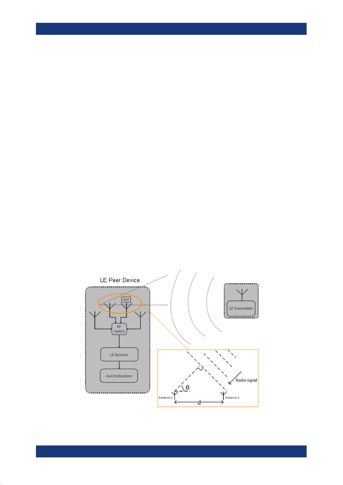
Angle of Arrival (AoA) method
A Bluetooth LE transmitter sends direction finding enabled packets using a single
antenna. A receiving Bluetooth LE peer device consists of an antenna array linked to
an RF switch which forwards the combined antennae signal to a Bluetooth LE receiver.
About the Bluetooth Options
About Bluetooth LE
The peer device switches its antennae while receiving parts of the packets and capturing I/Q samples. The I/Q samples are used to calculate the phase difference of the
radio signal received by different antennae of the array. For an array of two antennae
with distance d, frequency f of the radio signal and speed of light c, the phase difference ψ calculates as follows:
ψ = 2πd * cos(Θ) * f / c
The angle of arrival Θ is calculated as follows:
Θ = arccos((ψ * c) / (2πd * f))
Figure 2-10: Angle of Arrival method
27User Manual 1175.6803.02 ─ 21
Page 28
R&S®SMW-K60/-K117
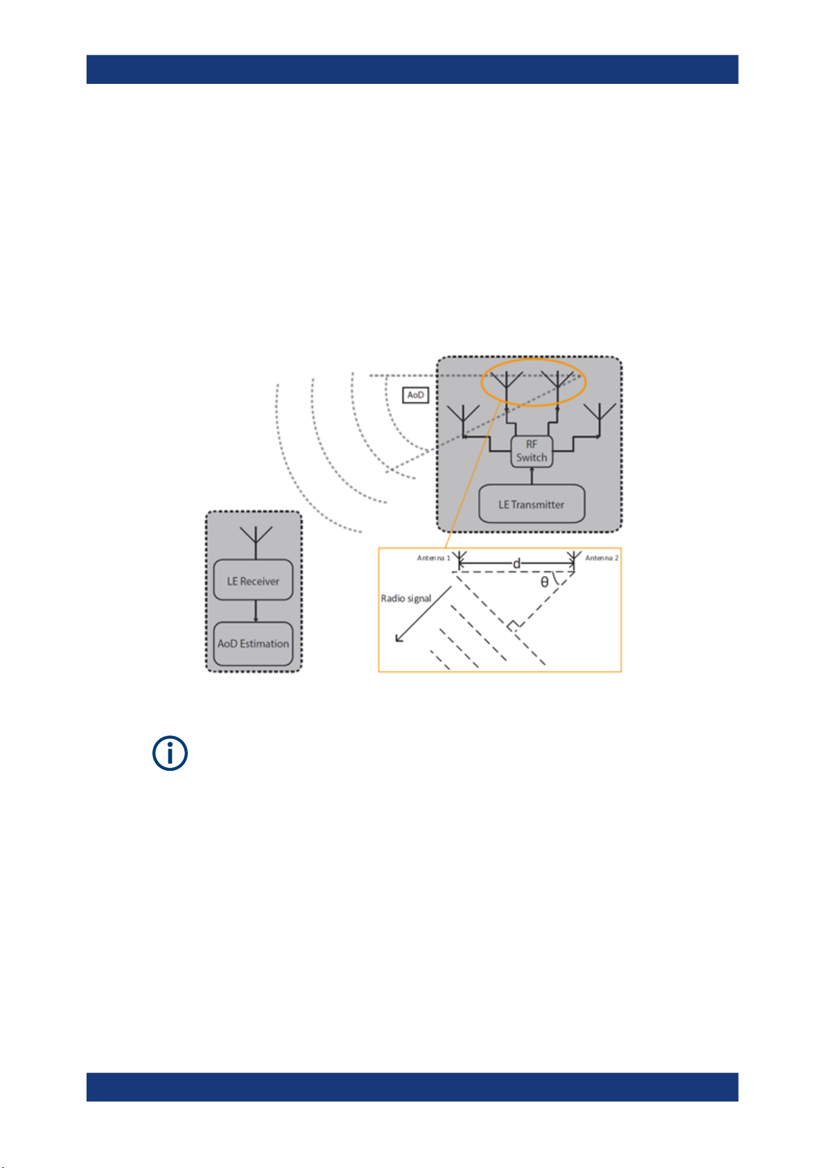
Angle of Departure (AoD) method
A Bluetooth LE transmitter sends direction finding enabled packets using an antenna
array. A receiving Bluetooth LE device, consisting of a single antenna, captures I/Q
samples and the geometry of the antenna array from profile-level information.
For an array with two antennae with distance d, frequency f of the radio signal and
speed of light c, the phase difference ψ calculates as follows:
ψ = 2πd * cos(Θ) * f / c
The angle of departure Θ is calculated as follows:
Θ = arccos((ψ * c) / (2πd * f))
About the Bluetooth Options
About Bluetooth LE
Figure 2-11: Angle of Departure method
The geometry of the antenna array is information that is shared between Bluetooth LE
transmitter and receiver on a profile-level. The antenna switching pattern and the
method of angle estimation is specified by Constant Tone Extension.
For more information, refer to section 8 Direction Finding Using Bluetooth Low Energy
of core specification for Bluetooth wireless technology, volume 1, part A.
Constant tone extension
To transmit direction finding information in packets in the Bluetooth LE Uncoded PHYs,
the link layer packet format is extended by an optional field Constant Tone Extension
(CTE) as illustrated in Figure 2-8. The field has a length between 16 µs and 160 µs
and consists of a constantly modulated series of unwhitened 1s. This modulation
results in a CW tone shifted by 250 kHz (LE1M) or 500 kHz (LE2M) from the LE channel center frequency.
28User Manual 1175.6803.02 ─ 21
Page 29

R&S®SMW-K60/-K117
The presence, type and length of CTE is specified in the CTEInfo field available for
ADV_SYNC_IND and ADV_CHAIN_IND PDUs.
CTETime RFU CTEType
Figure 2-12: CTEInfo field
The parts of the CTEInfo field are described in the table below. CTEType specifies, if
AoA or AoD method is used for direction finding.
CTEInfo field Length Value Description
CTETime 5 bit 2 to 20 CTE length = 8 µs * Value
RFU 1 bit 1 to 2 Reserved for future use
CTEType 2 bit 0 AoA Constant tone extension
About the Bluetooth Options
About Bluetooth LE
CTEInfo (8 bit)
Other values are reserved for future use.
1 AoD Constant tone extension with 1 µs slots
2 AoD Constant tone extension with 2 µs slots
3 Reserved for future use
If Bluetooth LE devices support AoA/AoD CTE, the antennae within the array follow a
switching pattern specified by the Host. After a guard and reference period, time slots
of 1 µs or 2 µs provide periods for antenna switching and I/Q sampling.
The following figure illustrates the CTE structure for AoA method. On the transmitting
side, there is no antenna switching. On the receiving side, antenna switching and I/Q
sampling alternate in the time slots after the guard and reference period.
29User Manual 1175.6803.02 ─ 21
Page 30

R&S®SMW-K60/-K117
About the Bluetooth Options
About Bluetooth LE
Figure 2-13: CTE structure for AoA method
The following figure illustrates the CTE structure for AoD method. On the transmitting
side, antenna switching and I/Q sampling alternate in the time slots after the guard and
reference period. On the receiving side, I/Q sampling only is performed in every second time slot after the guard and reference period.
30User Manual 1175.6803.02 ─ 21
Page 31

R&S®SMW-K60/-K117
About the Bluetooth Options
About Bluetooth LE
Figure 2-14: CTE structure for AoD method
For more information, refer to section 2.5 Constant Tone Extension and IQ Sampling of
core specification for Bluetooth wireless technology, volume 6, part B.
31User Manual 1175.6803.02 ─ 21
Page 32

R&S®SMW-K60/-K117
3 Bluetooth Configuration and Settings
Access:
► Select "Baseband > Bluetooth".
The remote commands required to define these settings are described in Chapter 5,
"Remote-Control Commands", on page 109.
Contents
● General Settings..................................................................................................... 32
● Dirty Transmitter Test.............................................................................................. 35
● Channel Settings - BR/EDR....................................................................................40
● Packet Configuration - BR/EDR..............................................................................42
● Channel Settings - LE............................................................................................. 49
● Event / Frame Configuration - LE............................................................................54
● Packet Configuration - LE....................................................................................... 63
● Test Packet Configuration - LE................................................................................88
Bluetooth Configuration and Settings
General Settings
3.1 General Settings
Access:
► Select "Baseband > Bluetooth".
The tab provides access to the default and the "Save/Recall" settings. The selected
Bluetooth mode and transport mode determine the available parameters.
32User Manual 1175.6803.02 ─ 21
Page 33

R&S®SMW-K60/-K117
Settings:
State..............................................................................................................................33
Set To Default................................................................................................................33
Save/Recall...................................................................................................................34
Generate Waveform......................................................................................................34
Bluetooth Version..........................................................................................................34
Bluetooth Mode.............................................................................................................34
Transport Mode.............................................................................................................34
Dirty Transmitter Test.................................................................................................... 35
Filter / Clipping.............................................................................................................. 35
Power Ramping.............................................................................................................35
State
Activates the standard and deactivates all the other digital standards and digital modulation modes in the same path.
Remote command:
[:SOURce<hw>]:BB:BTOoth:STATe on page 114
Bluetooth Configuration and Settings
General Settings
Set To Default
Calls the default settings. The values of the main parameters are listed in the following
table.
Parameter Value
State Not affected by "Set to default"
Bluetooth Version 4.2
5.x with R&S SMW-K117
Bluetooth Mode Basic Rate + EDR
Transport mode ACL (Asynchronous) + EDR
Packet Type DH1
Sequence Length 1 Frames
Slot Timing Tx Test Mode
Packet Configuration Packet Editor/ Whitening off
Dirty Transmitter Test Not in Use
Filter Gauss (FSK)
Clipping Clipping off
Power Ramping Cosine / 1 Symbols
Trigger Auto
Marker Restart
Clock Internal
Remote command:
[:SOURce<hw>]:BB:BTOoth:PRESet on page 113
33User Manual 1175.6803.02 ─ 21
Page 34

R&S®SMW-K60/-K117
Save/Recall
Accesses the "Save/Recall" dialog, that is the standard instrument function for saving
and recalling the complete dialog-related settings in a file. The provided navigation
possibilities in the dialog are self-explanatory.
The settings are saved in a file with predefined extension. You can define the filename
and the directory, in that you want to save the file.
See also, chapter "File and Data Management" in the R&S SMW user manual.
Remote command:
[:SOURce<hw>]:BB:BTOoth:SETTing:CATalog on page 113
[:SOURce<hw>]:BB:BTOoth:SETTing:LOAD on page 113
[:SOURce<hw>]:BB:BTOoth:SETTing:STORe on page 114
[:SOURce<hw>]:BB:BTOoth:SETTing:DELete on page 113
Generate Waveform
With enabled signal generation, triggers the instrument to save the current settings of
an arbitrary waveform signal in a waveform file with predefined extension *.wv. You
can define the filename and the directory, in that you want to save the file.
Using the ARB modulation source, you can play back waveform files and/or process
the file to generate multi-carrier or multi-segment signals.
Remote command:
[:SOURce<hw>]:BB:BTOoth:WAVeform:CREate on page 115
Bluetooth Configuration and Settings
General Settings
Bluetooth Version
Displays the current version of the standard.
The default settings and parameters provided are oriented towards the specifications
of the version displayed.
The displayed version for Bluetooth wireless technology depends on installed options.
E.g "Bluetooth Version = 5.1" in accordance with Bluetooth core specification v5.1,
requires R&S SMW-K117.
Remote command:
[:SOURce<hw>]:BB:BTOoth:VERSion? on page 115
Bluetooth Mode
Determines the Bluetooth mode.
"Basic Rate +EDR"
Selects the standard Bluetooth mode (BR+EDR).
Specific settings of the basic mode are described in Chapter 3.3,
"Channel Settings - BR/EDR", on page 40.
"Bluetooth Low Energy"
Selects the Bluetooth LE mode. Specific settings of this mode are
described in Chapter 3.5, "Channel Settings - LE", on page 49.
Remote command:
[:SOURce<hw>]:BB:BTOoth:BMODe on page 112
Transport Mode
Only available for "Bluetooth Mode " set to "Basic Rate + EDR"
34User Manual 1175.6803.02 ─ 21
Page 35

R&S®SMW-K60/-K117
Selects the transport mode.
"ACL+EDR"
"SCO"
"eSCO+EDR"
Remote command:
[:SOURce<hw>]:BB:BTOoth:TMODe on page 114
Dirty Transmitter Test
Accesses the Dirty Transmitter Test dialog, see page 35.
Filter / Clipping
Accesses the dialog for setting baseband filtering, the modulation settings and clipping,
see Chapter 4.1, "Filter/Clipping Settings", on page 93.
Bluetooth Configuration and Settings
Dirty Transmitter Test
The transport mode selected is used for a point-to-multipoint link
establishment between the master and all the slaves participating on
the piconet.
The transport mode selected is used for a point-to-point link establishment between a master and a single slave in the piconet.
The transport mode selected is used for a symmetric or asymmetric
point-to-point link establishment between a master and a specific
slave.
Power Ramping
Accesses the Power Ramping Settings dialog, see page 98.
3.2 Dirty Transmitter Test
Access:
► Select "Bluetooth > General > Dirty Transmitter Test"
The dialog contains the parameters for configuring the "Dirty Transmitter Test" settings.
35User Manual 1175.6803.02 ─ 21
Page 36

R&S®SMW-K60/-K117
These settings contain parameters you can change for the master signal. It is used to
test the connection under 'dirty transmitter' conditions, and to define the influence on
the receiver quality (bit error rate tests).
Dirty transmitter parameters according to the Bluetooth test specification are given in
the following tables.
Table 3-1: Dirty transmitter for BR according to the test specification
Bluetooth Configuration and Settings
Dirty Transmitter Test
Set Frequency offset in kHz Symbol timing error in
ppm
1 75 -20 0.28
2 14 -20 0.30
3 -2 20 0.29
4 1 20 0.32
5 39 20 0.33
6 0 -20 0.34
7 -42 -20 0.29
8 74 -20 0.31
9 -19 -20 0.28
10 -75 20 0.35
Table 3-2: Dirty transmitter for EDR according to the test specification
Set Frequency offset in kHz Symbol timing error in ppm
1 0 0
2 65 20
Modulation index
3 -65 -20
Table 3-3: Dirty transmitter for LE according to the test specification
Set Frequency offset in kHz Symbol timing error in
ppm
1 100 -50 0.45
2 19 -50 0.48
3 -3 50 0.46
4 1 50 0.52
5 52 50 0.53
6 0 -50 0.54
7 -56 -50 0.47
8 97 -50 0.50
9 -25 -50 0.45
10 -100 50 0.55
Modulation index (standard)
36User Manual 1175.6803.02 ─ 21
Page 37

R&S®SMW-K60/-K117
Table 3-4: Additional parameters for LE dirty transmitter according to the test specification
Set Stable modulation index
1 0.495
2 0.498
3 0.496
4 0.502
5 0.503
6 0.504
7 0.497
8 0.500
9 0.495
10 0.505
Settings:
Bluetooth Configuration and Settings
Dirty Transmitter Test
Set to Default................................................................................................................ 37
Dirty Transmitter Test.................................................................................................... 37
Start Phase................................................................................................................... 38
Modulation Index Mode.................................................................................................38
Frequency Drift Rate.....................................................................................................38
Frequency Drift Deviation (+/-)......................................................................................38
Number of Packets per Set...........................................................................................38
Dirty Transmitter Setting................................................................................................39
└ State................................................................................................................39
└ Carrier Frequency Offset kHz......................................................................... 39
└ Symbol Timing Error....................................................................................... 39
└ Modulation Index.............................................................................................39
Set to Default
Calls the default settings for the dirty transmitter test. Default settings are according to
the specification for Bluetooth wireless technology. The setting corresponds the
selected Bluetooth mode.
Remote command:
[:SOURce<hw>]:BB:BTOoth:DTTest:STDefault on page 118
Dirty Transmitter Test
Activates or deactivates the dirty transmitter test.
The setting is available for the following packet types:
●
BR: DH1, DH3, DH5
●
EDR: 2-DH1, 2-DH3, 2-DH5, 3-DH1, 3-DH3, 3-DH5, 2-EV3, 2-EV5, 3-EV3, 3-EV5
●
LE: Test packets and all advertising packet types listed in tables 3-5 and 3-6
For basic rate packets, each enabled set of parameters in the "Dirty Transmitter Setting" is used for a duration of 20 ms. After 20 ms, the following enabled set is used,
continuing with the first enabled set after the sequence is completed.
37User Manual 1175.6803.02 ─ 21
Page 38

R&S®SMW-K60/-K117
For EDR packets, the parameter sets apply for 20 packets each.
For LE, each enabled set of parameters in the "Dirty Transmitter Setting" is used. After
the specified Number of Packets per Set (specification defines 50 packets) is transmitted, a following enabled set is used. After the sequence is completed, the transmission
continues with the first enabled set.
Remote command:
[:SOURce<hw>]:BB:BTOoth:DTTest:DTTState on page 116
Start Phase
Enters a start phase.
The start phase of the sine wave used to drift the modulated Bluetooth signal around
center frequency + carrier frequency offset is set here.
Remote command:
[:SOURce<hw>]:BB:BTOoth:DTTest:SPHase on page 118
Modulation Index Mode
Option R&S SMW-K117
Bluetooth Configuration and Settings
Dirty Transmitter Test
For "Bluetooth Mode = Bluetooth Low Energy", specifies which one of the two possible
modulation index modes are used for dirty transmitter signal.
●
Standard mode determines the range of modulation index h = 0.450 to 0.550
●
Stable mode determines the range of modulation index h = 0.495 to 0.505
Remote command:
[:SOURce<hw>]:BB:BTOoth:DTTest:MIMode on page 117
Frequency Drift Rate
Enters a frequency drift rate.
A sine wave is used to drift the modulated Bluetooth signal around center frequency +
carrier frequency offset with the set frequency drift rate.
Remote command:
[:SOURce<hw>]:BB:BTOoth:DTTest:FDRate on page 117
Frequency Drift Deviation (+/-)
Enters a frequency drift deviation.
A sine wave is used to drift the modulated Bluetooth signal around center frequency +
carrier frequency offset. The maximum deviation reached during the drift equals the set
frequency drift deviation.
Remote command:
[:SOURce<hw>]:BB:BTOoth:DTTest:FDDeviation on page 117
Number of Packets per Set
For "Bluetooth Mode = Bluetooth Low Energy", specifies the number of test packets to
be transmitted per enabled dirty transmitter set.
Remote command:
[:SOURce<hw>]:BB:BTOoth:DTTest:NPPSet on page 118
38User Manual 1175.6803.02 ─ 21
Page 39

R&S®SMW-K60/-K117
Dirty Transmitter Setting
Indicates the dirty transmitter parameters according to the Bluetooth BR test specification.
State ← Dirty Transmitter Setting
Activates or deactivates the corresponding parameter set.
If deactivated, the parameters are skipped in the sequence, and the next active set is
used.
Remote commands ...:LONG:SET<ch>:... are used for BR and LE packets. The
instrument provides configuration of up to 10 sets (SET1 to SET10).
Remote commands ...:SHORt:SET<ch>:... are used for EDR packets. The
instrument provides configuration of up to 3 sets (SET1 to SET3).
For basic rate packets, each enabled set applies to 20ms of signal. For EDR packets,
each enabled set applies to 20 packets.
For LE, each enabled set applies to 50 test packets.
Remote command:
[:SOURce<hw>]:BB:BTOoth:DTTest:TABLe:LONG:SET<ch>:STATe
on page 120
[:SOURce<hw>]:BB:BTOoth:DTTest:TABLe:SHORt:SET<ch>:STATe
on page 121
Bluetooth Configuration and Settings
Dirty Transmitter Test
Carrier Frequency Offset kHz ← Dirty Transmitter Setting
Determines a carrier frequency offset.
The center frequency of the modulated RF carrier is offset by the specified value.
Remote command:
[:SOURce<hw>]:BB:BTOoth:DTTest:TABLe:LONG:SET<ch>:CFOFfset
on page 119
[:SOURce<hw>]:BB:BTOoth:DTTest:TABLe:SHORt:SET<ch>:CFOFfset
on page 121
Symbol Timing Error ← Dirty Transmitter Setting
Sets the symbol timing error in ppm.
The symbol timing error modifies the symbol clock frequency by the specified value.
Remote command:
[:SOURce<hw>]:BB:BTOoth:DTTest:TABLe:LONG:SET<ch>:STERror
on page 120
[:SOURce<hw>]:BB:BTOoth:DTTest:TABLe:SHORt:SET<ch>:STERror
on page 122
Modulation Index ← Dirty Transmitter Setting
(Only for basic rate packets)
Sets the modulation index.
The modulation index h specifies the frequency deviation, defined as:
39User Manual 1175.6803.02 ─ 21
Page 40

R&S®SMW-K60/-K117
Where is the "symbol rate" and is the "frequency deviation".
According to the Bluetooth specification, the modulation index can vary between 0.28
and 0.35.
Remote command:
[:SOURce<hw>]:BB:BTOoth:DTTest:TABLe:LONG:SET<ch>:MINDex
on page 119
3.3 Channel Settings - BR/EDR
This dialog provides access to the "Bluetooth Basic Rate + EDR" settings. For LE settings, refer to Chapter 3.5, "Channel Settings - LE", on page 49.
Bluetooth Configuration and Settings
Channel Settings - BR/EDR
Access:
1. Select "Bluetooth > General > Bluetooth Mode > Basic Rate + EDR".
2. Select "Channel".
The dialog contains the parameters to define the packet type and provides access to
the packet type configuration dialog. The graphic shows the frame structure of the
selected packet type.
Settings:
Packet Type.................................................................................................................. 41
Sequence Length..........................................................................................................41
Slot Timing.................................................................................................................... 41
Packet Configuration.....................................................................................................41
40User Manual 1175.6803.02 ─ 21
Page 41

R&S®SMW-K60/-K117
Packet Type
Selects the packet type.
The available packets depend on the selected Transport Mode.
All packet types as defined in the Bluetooth specification are supported. For an over-
view, see Chapter 2.2.1, "Bluetooth Packet Types for BR/EDR", on page 13.
Remote command:
[:SOURce<hw>]:BB:BTOoth:PTYPe on page 122
Sequence Length
Selects the sequence length in frames of the generated signal. The signal repeats after
the specified number of frames.
Remote command:
[:SOURce<hw>]:BB:BTOoth:SLENgth on page 123
Slot Timing
Selects the timing mode for the Rx slot.
The graphic below shows the frame structure of the selected Packet Type and slot tim-
ing.
Bluetooth Configuration and Settings
Channel Settings - BR/EDR
Tx test mode Loopback test mode
A transmitted packet has a duration of N × 625 μs where N is an odd integer larger
than 0. N depends on the type of the transmitted packet. In "Tx Test" mode, N = 1 for
Rx slots.
"Tx Test Mode"
The transmitted Rx package takes 625 symbols, regardless of the
selected packet type.
"Loopback Test Mode"
Extends the Rx slot time according to the selected packet type.
For example, the Rx slot of Packet Type > DH3 takes 3 x 625 symbols.
Remote command:
[:SOURce<hw>]:BB:BTOoth:STIMing on page 123
Packet Configuration
Access the "Packet Configuration" dialog, see Chapter 3.4, "Packet Configuration - BR/
EDR", on page 42.
The current data source for packet and the data whitening state are displayed next to
the button.
Remote command:
n.a.
41User Manual 1175.6803.02 ─ 21
Page 42

R&S®SMW-K60/-K117
3.4 Packet Configuration - BR/EDR
Access:
1. Select "Bluetooth > General > Bluetooth Mode > Basic Rate + EDR".
2. Select "Bluetooth > Channel > Packet Configuration".
Bluetooth Configuration and Settings
Packet Configuration - BR/EDR
The dialog contains the parameters for configuring the packet type. The available
parameters vary according to the selected Packet Type and data source.
Settings:
Packet Configuration.....................................................................................................43
└ Data Source for Packet...................................................................................43
└ Data Whitening............................................................................................... 43
└ Synchronize LAP with BD_ADDR...................................................................43
└ LAP for Sync Word......................................................................................... 43
└ Bluetooth Device Address (BD_ADDR)..........................................................43
Header.......................................................................................................................... 44
└ Logical Transport Address..............................................................................44
└ Flow Control....................................................................................................44
└ Acknowledgment.............................................................................................45
└ SEQN Start Value........................................................................................... 45
Payload......................................................................................................................... 45
└ Data Source....................................................................................................45
└ Data Length.................................................................................................... 46
└ EIR packet follows.......................................................................................... 46
└ Flow Control....................................................................................................46
└ Scan Repetition Mode.....................................................................................46
└ Class of Device...............................................................................................47
DV Payload................................................................................................................... 47
42User Manual 1175.6803.02 ─ 21
Page 43

R&S®SMW-K60/-K117
Data...............................................................................................................................49
Packet Configuration
In this section, specify general Bluetooth BR/EDR packet properties.
Data Source for Packet ← Packet Configuration
The data sent for each packet can be comfortably edited with the packet editor, or filled
with a predefined ALL data sequence.
"Packet Editor"
"All Data"
Remote command:
[:SOURce<hw>]:BB:BTOoth:PCONfiguration:DSFPacket on page 128
Bluetooth Configuration and Settings
Packet Configuration - BR/EDR
└ Data Source (Voice Field)...............................................................................47
└ Data Source....................................................................................................48
└ Data Length.................................................................................................... 48
└ Flow Control....................................................................................................49
└ Packet Length.................................................................................................49
Enables the edit mode to configure the packet fields individually.
Fills the generated packets with the selected data source. This mode
is useful if you need to load predefined data contents from a data list
file or the data contents of the packet are not of interest.
Data Whitening ← Packet Configuration
Activates the data whitening.
Evenly distributed white noise is ideal for the transmission, and real data can be forced
to look similar to white noise with different methods called "Data Whitening".
Remote command:
[:SOURce<hw>]:BB:BTOoth:PCONfiguration:DWHitening on page 128
Synchronize LAP with BD_ADDR ← Packet Configuration
(Available for FHS packets)
Activates synchronization of the LAP for Sync Word and the Bluetooth Device Address
> LAP.
Remote command:
[:SOURce<hw>]:BB:BTOoth:PCONfiguration:SLAP on page 131
LAP for Sync Word ← Packet Configuration
(Available for FHS packets)
Sets the 24 bits lower address part (LAP) in the 64 bits sync word separatly, if "Syn-
chronize LAP with BD_ADDR > OFF".
The LAP is obtained automatically from the Bluetooth device address "BD_ADDR >
LAP", if "Synchronize LAP with BD_ADDR > ON".
Remote command:
[:SOURce<hw>]:BB:BTOoth:PCONfiguration:LFSWord on page 129
Bluetooth Device Address (BD_ADDR) ← Packet Configuration
Enters the Bluetooth device address. Each Bluetooth device has allocated a unique
48-bit Bluetooth device address (BD_ADDR).
43User Manual 1175.6803.02 ─ 21
Page 44

R&S®SMW-K60/-K117
The BD_ADDR can take any values except the 64 reserved LAP values: 0x9E8B00 –
0x9E8B3F.
"NAP"
"UAP"
"LAP"
Remote command:
[:SOURce<hw>]:BB:BTOoth:PCONfiguration:BDANap on page 125
[:SOURce<hw>]:BB:BTOoth:PCONfiguration:BDAUap on page 125
[:SOURce<hw>]:BB:BTOoth:PCONfiguration:BDALap on page 124
Header
Access:
Select "Bluetooth > General > Bluetooth Mode > Basic Rate + EDR > Packet Configu-
ration > Header".
Bluetooth Configuration and Settings
Packet Configuration - BR/EDR
Selects non-significant address part.
The length of NAP is 16 bits or 4 hexadecimal figures.
Selects upper address part.
The length of UAP is 8 bits or two hexadecimal figures.
Selects lower address part.
The length of LAP is 24 bits or 6 hexadecimal figures.
Provides header settings.
Logical Transport Address ← Header
(Available for all packet types except ID)
Enters the logical transport address for the header.
Each slave active in a piconet is assigned a primary logical transport address
(LT_ADDR). The all-zero LT_ADDR is reserved for broadcast messages.
Remote command:
[:SOURce<hw>]:BB:BTOoth:PCONfiguration:LTADdress on page 130
Flow Control ← Header
(Available for all packet types except ID)
Sets the FLOW bit in the header. This bit indicates start or stop of transmission of
packets over the ACL logical transport.
"Go"
"Stop"
Remote command:
[:SOURce<hw>]:BB:BTOoth:PCONfiguration:HFControl on page 129
Allows the other devices to transmit new data.
Stops the other devices from transmitting data temporarily.
44User Manual 1175.6803.02 ─ 21
Page 45

R&S®SMW-K60/-K117
Acknowledgment ← Header
(Available for all packet types except ID)
Sets the ARQN bit of the packet header.
"NAK"
"ACK"
Remote command:
[:SOURce<hw>]:BB:BTOoth:PCONfiguration:ACKNowledgement on page 124
SEQN Start Value ← Header
(Available for all packet types except ID)
Sets the start value of the header SEQN bit.
The SEQN bit is present in the header to filter out retransmissions in the destination.
The signal generator is altering this bit automatically on consecutive frames, if a
sequence length of at least two frames is set.
"0"
"1"
Remote command:
[:SOURce<hw>]:BB:BTOoth:PCONfiguration:SNSValue on page 131
Bluetooth Configuration and Settings
Packet Configuration - BR/EDR
Request to retransmit the previous payload.
Previous payload has been received successfully.
The SEQN bit starts with 0.
The SEQN bit starts with 1.
Payload
Access:
Select "Bluetooth > General > Bluetooth Mode > Basic Rate + EDR > Packet Configu-
ration > Payload".
Provides payload settings.
Data Source ← Payload
(Available for all packet types except ID, POLL, NULL and FHS packets)
Selects the data source used for the payload.
The following standard data sources are available:
●
"All 0, All 1"
An internally generated sequence containing 0 data or 1 data.
●
"PNxx"
An internally generated pseudo-random noise sequence.
●
"Pattern"
An internally generated sequence according to a bit pattern.
Use the "Pattern" box to define the bit pattern.
●
"Data List/Select DList"
45User Manual 1175.6803.02 ─ 21
Page 46

R&S®SMW-K60/-K117
See also:
●
●
●
Remote command:
[:SOURce<hw>]:BB:BTOoth:PCONfiguration:DATA on page 126
[:SOURce<hw>]:BB:BTOoth:PCONfiguration:DATA:DPATtern on page 126
[:SOURce<hw>]:BB:BTOoth:PCONfiguration:DATA:DSELection on page 126
Data Length ← Payload
(Available for all packet types except ID, POLL, NULL and FHS packets)
Enters the payload data length in bytes.
Remote command:
[:SOURce<hw>]:BB:BTOoth:PCONfiguration:DLENgth on page 127
Bluetooth Configuration and Settings
Packet Configuration - BR/EDR
A binary data from a data list, internally or externally generated.
Select "Select DList" to access the standard "Select List" dialog.
– Select the "Select Data List > navigate to the list file *.dm_iqd > Select" to
select an existing data list.
– Use the "New" and "Edit" functions to create internally new data list or to edit
an existing one.
– Use the standard "File Manager" function to transfer external data lists to the
instrument.
Section "Modulation Data" in the R&S SMW user manual.
Section "File and Data Management" in the R&S SMW user manual.
Section "Data List Editor" in the R&S SMW user manual
EIR packet follows ← Payload
(Available for FHS packets)
Indicates that an extended inquiry response packet can follow.
"Yes"
"No"
Remote command:
[:SOURce<hw>]:BB:BTOoth:PCONfiguration:EIRPacketfollows
on page 129
Flow Control ← Payload
(Available for all packets types except ID, POLL, NULL, FHS, HV1, HV2, HV3, EV3,
EV4, EV5, 2-EV3, 2-EV5, 3-EV3, 3-EV5 packets.)
Sets the FLOW bit in the payload (flow control per logical link)
"Go"
"Stop"
Remote command:
[:SOURce<hw>]:BB:BTOoth:PCONfiguration:PFControl on page 130
Scan Repetition Mode ← Payload
(Available for FHS packets)
Indicates that an EIR packet follows.
Indicates that EIR does not follow.
Indicates start of transmission of ACL packets after a new connection
has been established.
Indicates stop of transmission of ACL packets before an additional
amount of payload data is sent.
46User Manual 1175.6803.02 ─ 21
Page 47

R&S®SMW-K60/-K117
The 2-bit scan repetition field indicates the interval between two consecutive page
scan windows, determines the behavior of the paging device.
"R0"
"R1"
"R2"
Remote command:
[:SOURce<hw>]:BB:BTOoth:PCONfiguration:SRMode on page 132
Class of Device ← Payload
(Available for FHS packets)
A parameter received during the device discovery procedure, indicates the type of
device and which types of service that are supported.
Remote command:
[:SOURce<hw>]:BB:BTOoth:PCONfiguration:CODevice on page 125
DV Payload
Access:
Select "Bluetooth > Transport Mode = SCO > Channel > Packet Type = DV > Packet
Configuration > Data Source for Packet = Packet Editor > DV Payload".
Bluetooth Configuration and Settings
Packet Configuration - BR/EDR
The scan interval is equal to the scan window Tw page scan (continuous scan) and maximal 1.28s.
The scan interval is maximal 1.28s.
The scan interval is maximal 2.56s.
Provides DV payload settings.
Data Source (Voice Field) ← DV Payload
(Available for DV packets)
Selects the data source for the voice field.
The following standard data sources are available:
●
"All 0, All 1"
An internally generated sequence containing 0 data or 1 data.
●
"PNxx"
An internally generated pseudo-random noise sequence.
●
"Pattern"
An internally generated sequence according to a bit pattern.
Use the "Pattern" box to define the bit pattern.
●
"Data List/Select DList"
A binary data from a data list, internally or externally generated.
Select "Select DList" to access the standard "Select List" dialog.
47User Manual 1175.6803.02 ─ 21
Page 48

R&S®SMW-K60/-K117
See also:
●
●
●
Remote command:
[:SOURce<hw>]:BB:BTOoth:PCONfiguration:VDATa on page 132
[:SOURce<hw>]:BB:BTOoth:PCONfiguration:DATA:VDPAttern on page 127
[:SOURce<hw>]:BB:BTOoth:PCONfiguration:DATA:VDSElection
on page 127
Data Source ← DV Payload
(Available for all packet types except ID, POLL, NULL and FHS packets)
Selects the data source used for the payload.
The following standard data sources are available:
●
●
●
●
See also:
●
●
●
Bluetooth Configuration and Settings
Packet Configuration - BR/EDR
– Select the "Select Data List > navigate to the list file *.dm_iqd > Select" to
select an existing data list.
– Use the "New" and "Edit" functions to create internally new data list or to edit
an existing one.
– Use the standard "File Manager" function to transfer external data lists to the
instrument.
Section "Modulation Data" in the R&S SMW user manual.
Section "File and Data Management" in the R&S SMW user manual.
Section "Data List Editor" in the R&S SMW user manual
"All 0, All 1"
An internally generated sequence containing 0 data or 1 data.
"PNxx"
An internally generated pseudo-random noise sequence.
"Pattern"
An internally generated sequence according to a bit pattern.
Use the "Pattern" box to define the bit pattern.
"Data List/Select DList"
A binary data from a data list, internally or externally generated.
Select "Select DList" to access the standard "Select List" dialog.
– Select the "Select Data List > navigate to the list file *.dm_iqd > Select" to
select an existing data list.
– Use the "New" and "Edit" functions to create internally new data list or to edit
an existing one.
– Use the standard "File Manager" function to transfer external data lists to the
instrument.
Section "Modulation Data" in the R&S SMW user manual.
Section "File and Data Management" in the R&S SMW user manual.
Section "Data List Editor" in the R&S SMW user manual
Remote command:
[:SOURce<hw>]:BB:BTOoth:PCONfiguration:DATA on page 126
[:SOURce<hw>]:BB:BTOoth:PCONfiguration:DATA:DPATtern on page 126
[:SOURce<hw>]:BB:BTOoth:PCONfiguration:DATA:DSELection on page 126
Data Length ← DV Payload
(Available for all packet types except ID, POLL, NULL and FHS packets)
48User Manual 1175.6803.02 ─ 21
Page 49

R&S®SMW-K60/-K117
Enters the payload data length in bytes.
Remote command:
[:SOURce<hw>]:BB:BTOoth:PCONfiguration:DLENgth on page 127
Flow Control ← DV Payload
(Available for all packets types except ID, POLL, NULL, FHS, HV1, HV2, HV3, EV3,
EV4, EV5, 2-EV3, 2-EV5, 3-EV3, 3-EV5 packets.)
Sets the FLOW bit in the payload (flow control per logical link)
"Go"
"Stop"
Remote command:
[:SOURce<hw>]:BB:BTOoth:PCONfiguration:PFControl on page 130
Data
Access:
Select "Packet Configuration > Data Source for Packet = All Data > Data".
Bluetooth Configuration and Settings
Channel Settings - LE
Indicates start of transmission of ACL packets after a new connection
has been established.
Indicates stop of transmission of ACL packets before an additional
amount of payload data is sent.
Provides data settings.
Packet Length ← Data
(Available in "All Data" mode and for all packet types except ID packet)
Enters the packet length in symbols.
Remote command:
[:SOURce<hw>]:BB:BTOoth:PCONfiguration:PLENgth on page 131
3.5 Channel Settings - LE
This dialog provides access to the Bluetooth Low Energy (LE) settings. For BR/EDR
settings, refer to Chapter 3.3, "Channel Settings - BR/EDR", on page 40.
Access:
1. Select "Bluetooth > General > Bluetooth Mode > Bluetooth Low Energy".
2. Select "Channel".
The "Channel" dialog varies depending on the selected "Channel Type"
49User Manual 1175.6803.02 ─ 21
Page 50

R&S®SMW-K60/-K117
Bluetooth Configuration and Settings
Channel Settings - LE
Bluetooth LE "Channel Type Advertising" Bluetooth LE "Channel Type Data"
The dialogs contain the parameters to define the packet type and provide access
to the packet type configuration dialogs. The graphic shows the frame structure of
the selected packet type.
Settings:
Channel Type................................................................................................................50
Packet Type.................................................................................................................. 50
Packet Format...............................................................................................................52
Duty Cycle.....................................................................................................................52
Sequence Length..........................................................................................................53
Bluetooth Controller Role..............................................................................................53
Bluetooth Controller State.............................................................................................53
Corrupted CRC Every 2nd Packet................................................................................ 54
Payload Type................................................................................................................ 54
Duration.........................................................................................................................54
Modulation Format........................................................................................................ 54
Event / Frame Configuration......................................................................................... 54
Test Packet Configuration............................................................................................. 54
Channel Type
Determines the channel type. Advertising and data are available. Refer to Chapter 3.6,
"Event / Frame Configuration - LE", on page 54 for setting the respective parameters.
"Advertising"
"Data"
Selects channel type advertising.
Selects the data channel type.
Devices in a connected state transmit the data channel packets in
connection events with a start point and an interval.
Remote command:
[:SOURce<hw>]:BB:BTOoth:CTYPe on page 134
Packet Type
Selects the packet type.
The available packet types depend on the selected channel type, as shown in the
tables below (Table 3-5).
50User Manual 1175.6803.02 ─ 21
Page 51

R&S®SMW-K60/-K117
Table 3-5: Packet types of the respective channel types:
Bluetooth Configuration and Settings
Channel Settings - LE
Packet type Adver-
tising
ADV_IND x -
ADV_DIRECT_IND x - DATA - x
ADV_NONCONN_IND x - all CONTROL_DATA ... - x
ADV_SCAN_IND x - TEST PACKET x x
SCAN_REQ x - CONTINUOUS x x
SCAN_RSP x -
Table 3-6: Additional packet types within R&S SMW-K117:
Packet type Adver-
tising
ADV_EXT_IND *) x -
AUX_ADV_IND x - AUX_SCAN_RSP x -
AUX_CHAIN_IND x - AUX_CONNECT_REQ x -
AUX_SYNC_IND x - AUX_CONNECT_RSP x -
Data
Data
Packet type Adver-
tising
CONNECT_IND x -
Packet type Adver-
tising
AUX_SCAN_REQ x -
Data
Data
*) Packet type ADV_EXT_IND is only supported with LE 1M and LE coded PHY. All
remaining packet types are supported with LE 1M, LE 2M and LE coded PHY
Depending on the Bluetooth Controller Role (master or slave), you can determine in
detail the information of the "CONTROL_DATA", as shown in the following tables
Table 3-7.
Table 3-7: Control information, available for master or slave.
CONTROL_DATA Master Slave
LL_CONNECTION_UPDATE_IND
LL_CHANNEL_MAP_IND x -
LL_TERMINATE_IND x x
LL_ENC_REQ x -
LL_ENC_RSP - x
LL_START_ENC_REQ x x
LL_START_ENC_RSP x x
Table 3-8: Additional control information within R&S SMW-K117:
CONTROL_DATA Master Slave
LL_SLAVE_FEAT_REQ - x
LL_CONNECTION_PARAM_REQ
x -
x x
CONTROL_DATA Master Slave
LL_UNKNOWN_RSP - x
LL_FEATURE_REQ x -
LL_FEATURE_RSP - x
LL_PAUSE_ENC_REQ x -
LL_PAUSE_ENC_RSP - x
LL_VERSION_IND x x
LL_REJECT_IND x x
CONTROL_DATA Master Slave
LL_PHY_RSP - x
LL_PHY UPDATE_IND x -
51User Manual 1175.6803.02 ─ 21
Page 52

R&S®SMW-K60/-K117
Bluetooth Configuration and Settings
Channel Settings - LE
CONTROL_DATA Master Slave
LL_CONNECTION_PARAM_RSP
LL_REJECT_EXT_IND x x
LL_PING_REQ x x
LL_PING_RSP x x
LL_LENGTH_REQ x x
LL_LENGTH__RSP x x
LL_PHY_REQ x x
- x
CONTROL_DATA Master Slave
LL_MIN_USED_CHANNELS_IND
LL_CTE_REQ x x
LL_CTE_RSP x x
LL_PERIODIC_SYNC_IND x x
LL_CLOCK_ACCURACY_REQ
LL_CLOCK_ACCURACY_RSP
The graphic shows the frame structure of the selected packet type.
Remote command:
[:SOURce<hw>]:BB:BTOoth:UPTYpe on page 135
- x
x x
x x
Packet Format
The R&S SMW provides packets for LE uncoded 1 Msymbol/s (LE 1M) physical layer
(PHY), LE coded 1 Msymbol/s PHY and LE uncoded 2 Msymbol/s (LE 2M) PHY. See
also Table 2-22.
Option R&S SMW-K117 is required for LE 2M PHY and LE coded PHY.
Remote command:
[:SOURce<hw>]:BB:BTOoth:PFORmat on page 135
Duty Cycle
Specifies duty cycle for directed advertising. Information is signaled via
ADV_DIRECT_IND.
Low: The packet is transmitted respecting advertising event interval
SOURCE1:BB:BTOoth:ECONfiguration:AEINterval and advertising event delay
High: The packet is transmitted respecting advertising event interval
SOURCE1:BB:BTOoth:ECONfiguration:ADINterval
Option R&S SMW-K117 is required.
See also "Advertising Event Interval" on page 57.
Remote command:
[:SOURce<hw>]:BB:BTOoth:DCYCle on page 134
52User Manual 1175.6803.02 ─ 21
Page 53

R&S®SMW-K60/-K117
Sequence Length
Selects the number of frames or events depending on the packet type. The signal
repeats after the specified number of frames/events.
Almost all packet types use sequence length in "Events".
Only for the following packet types, the sequence length is expressed in "Frames":
●
●
●
●
For LL_TERMINATE_IND packets, a default value according to the specification is
given:
●
●
For all other packet types, the sequence length is expressed in "Events".
Remote command:
[:SOURce<hw>]:BB:BTOoth:USLength on page 137
Bluetooth Configuration and Settings
Channel Settings - LE
SCAN_REQ
CONNECT_IND
AUX_SCAN_REQ
AUX_CONNECT_REQ
Master: 'SlaveLatency + 6'
Slave: '6'
Bluetooth Controller Role
Determines the controller role.
Depending on the channel type, the field either displays the appropriate role or you can
select one:
●
"Advertiser"
Displays the controller role corresponding to the packet type:
– "Advertiser" for TEST PACKET and for all ADV-xxx packet types and
SCAN_RSP.
Within R&S SMW-K117 also for all AUX-xxx packet types except for
AUX_SCAN_REQ and AUX_CONNECT_REQ
– "Scanner" for SCAN_REQ packet type.
Within R&S SMW-K117 also for AUX_SCAN_REQ
– "Initiator" for CONNECT_IND packet type
Within R&S SMW-K117 also for AUX_CONNECT_REQ
See also "Payload" on page 24.
●
"Data"
Assigns a role to the controller:
– "Master"
– "Slave"
See also Table 3-7.
Remote command:
[:SOURce<hw>]:BB:BTOoth:BCRole on page 133
Bluetooth Controller State
Shows the state of the Bluetooth controller. See also "Payload" on page 24.
Remote command:
[:SOURce<hw>]:BB:BTOoth:BCText? on page 112
53User Manual 1175.6803.02 ─ 21
Page 54

R&S®SMW-K60/-K117
Corrupted CRC Every 2nd Packet
If enabled, sets the ratio of packets with CRC faults to 50%. 50% of packets are generated with correct CRC. This setting is appropriate for packet error rate (PER) report
integrity tests.
Remote command:
[:SOURce<hw>]:BB:BTOoth:CCRC:STATe on page 134
Payload Type
Specifies the pattern to be transmitted continuously for the Packet Type set to CONTINUOUS. The packet header is not transmitted. For the supported payload types,
refer to "Payload Type" on page 91.
Duration
Specifies the transmission duration of CONTINUOUS packet.
Remote command:
[:SOURce<hw>]:BB:BTOoth:DURation on page 137
Modulation Format
Specifies the physical layer used for CONTINUOUS packet.
Remote command:
[:SOURce<hw>]:BB:BTOoth:MFORmat on page 137
Bluetooth Configuration and Settings
Event / Frame Configuration - LE
Event / Frame Configuration
Access the "Event Configuration" dialog, if the sequence length of the packet type is
expressed in events, and accordingly, the "Frame Configuration" dialog, if it is
expressed in frames, see Chapter 3.6, "Event / Frame Configuration - LE",
on page 54.
The data whitening state is displayed next to the button, refer to "Data Whitening"
on page 64.
Test Packet Configuration
For "Bluetooth Mode = Bluetooth Low Energy", accesses "Test Packet Configuration"
dialog for packet type "TEST PACKET".
See Chapter 3.8, "Test Packet Configuration - LE", on page 88.
3.6 Event / Frame Configuration - LE
Access:
1. Select "Bluetooth > General > Bluetooth Mode > Bluetooth Low Energy"
2. Select "Channel > Event / Frame Configuration".
The "Event" or "Frame" dialogs vary, depending on the used channel type:
54User Manual 1175.6803.02 ─ 21
Page 55

R&S®SMW-K60/-K117
Bluetooth Configuration and Settings
Event / Frame Configuration - LE
Figure 3-1: Event configuration dialog of the advertising channel type (advertiser)
Figure 3-2: Frame configuration dialog of the advertising channel type (scanner)
55User Manual 1175.6803.02 ─ 21
Page 56

R&S®SMW-K60/-K117
Bluetooth Configuration and Settings
Event / Frame Configuration - LE
Figure 3-3: Event configuration dialog of the data channel type
The dialogs contain the parameters to configure the event or frame settings, and
provide access to the packet configuration dialogs. The graphics show the distribution of the packets, the physical channel mapping and the channel indices. The
channel table gives an overview of the used channels and their assignments.
Contents
● Advertising Event / Frame Settings.........................................................................56
● Data Event Settings................................................................................................ 59
● Channel Table Settings........................................................................................... 61
3.6.1 Advertising Event / Frame Settings
The following section describes the parameters necessary for the advertising event or
frame configuration.
Settings:
Advertising Event Interval............................................................................................. 57
Periodic Advertising Interval..........................................................................................57
Advertising Event Delay................................................................................................57
Scan Window................................................................................................................ 57
Scan Interval................................................................................................................. 57
Advertising Packet Interval............................................................................................58
Transmit Window Offset................................................................................................58
Transmit Window Size...................................................................................................58
Packet Configuration.....................................................................................................58
Channel Table............................................................................................................... 59
56User Manual 1175.6803.02 ─ 21
Page 57

R&S®SMW-K60/-K117
Advertising Event Interval
Sets the time interval between two consecutive advertising events, regarding the starting points.
Note: This parameter is relevant for advertising event configuration and for the packet
types ADV_IND, ADV_DIRECT_IND, ADV_NONCONN_IND and ADV_SCAN_IND.
Within the option R&S SMW-K117, the following packet types are also relevant for the
setting: ADV_EXT_IND, AUX_ADV_IND, AUX_CHAIN_IND.
Remote command:
For packet type "ADV_DIRECT_IND" and duty cycle high:
[:SOURce<hw>]:BB:BTOoth:ECONfiguration:ADINterval on page 141
For all others:
[:SOURce<hw>]:BB:BTOoth:ECONfiguration:AEINterval on page 141
Periodic Advertising Interval
Sets the time interval between the start of two AUX_SYNC_IND PDUs from the same
advertising set.
Option R&S SMW-K117 is required.
Bluetooth Configuration and Settings
Event / Frame Configuration - LE
Remote command:
[:SOURce<hw>]:BB:BTOoth:ECONfiguration:PCONfiguration:PAINterval
on page 144
Advertising Event Delay
Sets a time delay between the start times of two consecutive advertising events. The
value is added to the advertising event interval.
Note: This parameter is relevant for advertising event configuration and for the packet
types ADV_IND, ADV_DIRECT_IND with low duty cycle, ADV_NONCONN_IND and
ADV_SCAN_IND.
Within the option R&S SMW-K117, the following packet types are also relevant for the
setting: ADV_EXT_IND, AUX_ADV_IND, AUX_CHAIN_IND.
Remote command:
[:SOURce<hw>]:BB:BTOoth:ECONfiguration:AEDelay on page 140
Scan Window
Sets the length of the window during which the scanner is operating in the advertising
channel.
Note that the scan window is less or equal to the value of the scan interval.
Note: This parameter is relevant for advertising frame configuration and for the packet
type SCAN_REQ.
Within the option R&S SMW-K117, the packet type AUX_SCAN_REQ is also relevant
for the setting.
Remote command:
[:SOURce<hw>]:BB:BTOoth:ECONfiguration:SWINdow on page 147
Scan Interval
Sets the time interval between the starting points of two consecutive windows during
which the scanner is operating in an advertising channel.
57User Manual 1175.6803.02 ─ 21
Page 58

R&S®SMW-K60/-K117
Note: This parameter is relevant for advertising frame configuration and for the packet
type SCAN_REQ.
Within the option R&S SMW-K117, the packet type AUX_SCAN_REQ is also relevant
for the setting.
Remote command:
[:SOURce<hw>]:BB:BTOoth:ECONfiguration:SINTerval on page 146
Advertising Packet Interval
Sets the time interval between packets starting points of two consecutive packets in
the advertising channel.
Note: This parameter is relevant for advertising frame configuration and for the packet
type SCAN_RSP.
Within the option R&S SMW-K117, the packet type AUX_SCAN_RSP is also relevant
for the setting.
Remote command:
[:SOURce<hw>]:BB:BTOoth:ECONfiguration:APINterval on page 141
Transmit Window Offset
Displays the start point of the transmit window.
Note: This parameter is relevant for advertising frame configuration and for the packet
type CONNECT_IND.
Within the option R&S SMW-K117, the following packet types are also relevant for the
setting: AUX_CONNECT_REQ, AUX_CONNECT_RSP.
This parameter is set in the packet configuration dialog, see "Transmit Window Offset"
on page 75.
Remote command:
[:SOURce<hw>]:BB:BTOoth:ECONfiguration:PCONfiguration:WOFFset
on page 183
Bluetooth Configuration and Settings
Event / Frame Configuration - LE
Transmit Window Size
Indicates the size of the transmit window, regarding to the start point.
Note that the scan window size is less or equal to the value of the connection interval.
Note: This parameter is relevant for advertising frame configuration and for the packet
type CONNECT_IND.
Within the option R&S SMW-K117, the following packet types are also relevant for the
setting: AUX_CONNECT_REQ, AUX_CONNECT_RSP.
The parameter is set in the packet configuration dialog, see "Transmit Window Size"
on page 75.
Remote command:
[:SOURce<hw>]:BB:BTOoth:ECONfiguration:WSINfo? on page 147
Packet Configuration
Opens the dialog for setting the corresponding packet configuration.
This dialog is described in Chapter 3.7, "Packet Configuration - LE", on page 63.
58User Manual 1175.6803.02 ─ 21
Page 59

R&S®SMW-K60/-K117
Channel Table
Selects the channel to be used for configured packets. The description is covered in
Chapter 3.6.3, "Channel Table Settings", on page 61.
3.6.2 Data Event Settings
The following section describes the parameters necessary for the data event connection.
Settings:
No. of Tx Packets per Event......................................................................................... 59
Connection Event Interval ............................................................................................59
LL Connection Mode.....................................................................................................59
Long Term key (hex)..................................................................................................... 61
Selected Data Channel Index....................................................................................... 61
No. of Tx Packets per Event
Sets the number of Tx packets per event. Each connection contains at least one data
channel packet. The maximum number of packets per event is determined by the duration of the connection event interval.
Note: This parameter is relevant for data event connection settings.
Remote command:
[:SOURce<hw>]:BB:BTOoth:ECONfiguration:PNUMber on page 146
Bluetooth Configuration and Settings
Event / Frame Configuration - LE
Connection Event Interval
Set the time interval between the start points of two consecutive connection events.
Subsequent transmissions within an event are separated by this parameter to separate
connecting event starting points in time.
Note: This parameter is relevant for data event connection settings and advertising
frame configuration with the packet type DATA and all CONTROL_DATA packet types.
Remote command:
[:SOURce<hw>]:BB:BTOoth:ECONfiguration:PCONfiguration:CINTerval
on page 167
LL Connection Mode
Select the link layer connection mode. To provide safe transmission of payload data,
the data in the packet can be encrypted. If activated, the payload data follows MIC
(message authentication code).
Note: This parameter is relevant for data event connection settings.
The following table shows which types of packets can be encrypted and / or unencryp-
ted.
59User Manual 1175.6803.02 ─ 21
Page 60

R&S®SMW-K60/-K117
Table 3-9: Data packet encryption
Bluetooth Configuration and Settings
Event / Frame Configuration - LE
Packet type encryp-
ted
DATA x x
LL_CONNECTION_UPDATE_IND
LL_CHANNEL_MAP_IND x x LL_FEATURE_RSP x x
LL_TERMINATE_IND x x LL_PAUSE_ENC_REQ - x
LL_ENC_REQ - x LL_PAUSE_ENC_RSP x -
LL_ENC_RSP - x
LL_START_ENC_REQ - x
LL_START_ENC_RSP x -
Table 3-10: Encryption of additional packet types within R&S SMW-K117:
Packet type encryp-
LL_SLAVE_FEATURE_REQ x x
LL_CONNECTION_PARAM_REQ
LL_CONNECTION_PARAM_RSP
x x LL_FEATURE_REQ x x
ted
x x LL_PHY_UPDATE_IND x x
x x LL_MIN_USE_CHAN-
unencrypted
unencrypted
Packet type encryp-
ted
LL_UNKNOWN_RSP x x
LL_VERSION_IND x x
LL_REJECT_IND x x
Packet type encryp-
ted
LL_PHY_RSP x x
x x
NELS_IND
unencrypted
unencrypted
LL_REJECT_EXT_IND x x LL_CTE_REQ x x
LL_PING_REQ x x
LL_PING_RSP x x
LL_LENGTH_REQ x x
LL_LENGTH_RSP x x
LL_PHY_REQ x x
"Un-encrypted"
Payload data is transmitted without encoding. Example of packet type
LL_CTE_RSP x x
LL_PERIODIC_SYNC_IND x x
LL_CLOCK_ACCURACY_REQ
LL_CLOCK_ACCURACY_RSP
x x
x x
data:
60User Manual 1175.6803.02 ─ 21
Page 61

R&S®SMW-K60/-K117
Bluetooth Configuration and Settings
Event / Frame Configuration - LE
"Encrypted"
Remote command:
[:SOURce<hw>]:BB:BTOoth:ECONfiguration:LCMode on page 142
Long Term key (hex)
Indicates the time the controller needs to receive the long-term key from the host. After
this time, the controller is ready to enter into the last phase of encryption mode setup.
Note: This parameter is relevant for data event connection settings. In encrypted
mode, the code can be edited.
Remote command:
[:SOURce<hw>]:BB:BTOoth:ECONfiguration:LTKey on page 142
Selected Data Channel Index
Indicates the number of the first active data channel.
The data channel is selected for each connection event. The master and slave deter-
mine the used data channel by selecting from the list of used channels (see "Channel
Table" on page 62).
Note: This parameter is relevant for data event connection settings.
Displays the data channel index currently selected.
Remote command:
[:SOURce<hw>]:BB:BTOoth:ECONfiguration:SDCI? on page 146
The link layer connection runs in encrypted mode. Example of packet
type data:
3.6.3 Channel Table Settings
Access:
1. Follow the directions in Chapter 3.6, "Event / Frame Configuration - LE",
on page 54.
61User Manual 1175.6803.02 ─ 21
Page 62

R&S®SMW-K60/-K117
2. Select "Channel Table"
Bluetooth Configuration and Settings
Event / Frame Configuration - LE
The dialog varies, depending on the used channel type.
The channel table displays all possible channels and with their characteristics and
selects the channels to be used for generated packets. Channel frequencies are indicated above the channel table.
Settings:
Channel Table
The channel table displays configured parameters characterizing the channel and the
current state.
Every channel is represented with bit positioned as per the data channel index. LSB
represents data channel index 0 and the bit in position 36 represents data channel
index 36.
If the channel is used, its channel bit is to be set to '1'. Bit value '0' indicates that the
channel is unused.
The bits in positions 37, 38 and 39 must be set to zero upon transmission and ignored
upon receipt.
"Center Frequency"
Indicates the center frequency of a channel. The graphical representation is displayed above the channel table.
"Channel Index"
Indicates the channel index. The graphical representation is displayed above the channel table.
"Channel Type"
Indicates the channel type. The graphical representation of possible
transmission position is displayed above the channel table.
62User Manual 1175.6803.02 ─ 21
Page 63

R&S®SMW-K60/-K117
"Channel State"
Remote command:
[:SOURce<hw>]:BB:BTOoth:ECONfiguration:ACTable:CHANnel<ch0>:
STATe on page 140
[:SOURce<hw>]:BB:BTOoth:ECONfiguration:DCTable:CHANnel<ch0>:
STATe on page 140
[:SOURce<hw>]:BB:BTOoth:ECONfiguration:PCONfiguration:DCMTable:
CHANnel<ch0>:STATe on page 140
3.7 Packet Configuration - LE
Access:
1. Select "Bluetooth > General > Bluetooth Mode > Bluetooth LE".
Bluetooth Configuration and Settings
Packet Configuration - LE
Specifies the channels to be used for generated packets.
2. Select "Channel > Channel Type, Packet Type > DATA > Event/Frame Configuration", according to the selected packet type.
3. In the corresponding "Event" or "Frame" dialog, select "Packet Configuration".
The dialog contains the parameters for configuring the selected packet type.
Contents:
● General Packet Configuration.................................................................................63
● Header Configuration..............................................................................................64
● Main Payload Configuration Dialog.........................................................................68
● Additional Payload Configuration Dialogs...............................................................84
3.7.1 General Packet Configuration
This section describes the upper part of configuration dialog - "Packet Configuration".
63User Manual 1175.6803.02 ─ 21
Page 64

R&S®SMW-K60/-K117
Settings:
Data Whitening..............................................................................................................64
Access Address............................................................................................................ 64
Data Whitening
Activates or deactivates the data whitening.
Evenly distributed white noise is ideal for the transmission and real data can be forced
to look similar to white noise with different methods called "Data Whitening". Applied to
the PDU and CRC fields of all packet types, whitening is used to avoid long equal
sequences in the data bit stream.
Remote command:
[:SOURce<hw>]:BB:BTOoth:ECONfiguration:PCONfiguration:DWHitening
on page 154
Access Address
Sets the access address of the link layer connection.
Bluetooth LE transmissions are based on an interface packet format, that consists of a
preamble (8 bits), the access address (32 bits), the PDU and CRC (24 bits).
Access address is used to identify communications on a physical channel, and to
exclude or ignore packets on different physical channels. The channels are using the
same PHY channels in physical proximity.
The structure of access address depends on the packet type:
●
●
Note: This parameter is relevant for all available package types specified in event or
frame configuration of a data or advertiser channel.
Remote command:
[:SOURce<hw>]:BB:BTOoth:ECONfiguration:PCONfiguration:AADDress
on page 154
Bluetooth Configuration and Settings
Packet Configuration - LE
Data channel packets
The access address is a pseudo-random LL connection address, generated by the
initiator of the LL connection. The address has to follow some specific rules, which
are described in the Bluetooth LE technology.
Advertising channel packets
The address is fixed to 01101011011111011001000101110001 with the leftmost bit
sent first and being the LSB.
3.7.2 Header Configuration
1. Follow the description in Chapter 3.7, "Packet Configuration - LE", on page 63.
64User Manual 1175.6803.02 ─ 21
Page 65

R&S®SMW-K60/-K117
2. Select "Header".
Settings:
NESN Start Value..........................................................................................................65
SN Start Value...............................................................................................................65
Channel Selection.........................................................................................................65
CRC Initial.....................................................................................................................66
CTEInfo Present............................................................................................................66
CTEInfo Configuration...................................................................................................66
Devices Tx/Rx Address Type........................................................................................67
Bluetooth Configuration and Settings
Packet Configuration - LE
The dialog provides header settings.
└ CTETime.........................................................................................................67
└ CTEType.........................................................................................................67
└ Antenna Number.............................................................................................67
└ AntennaX Gain................................................................................................67
NESN Start Value
Sets the start value of the next expected packet from the same device in the LL connection ("Next Expected Sequence Number"). This parameter can be set in the first
event. From the second event, this field is not indicated.
Note: This parameter is relevant for data event configuration and all data channel
packet types except TEST PACKET.
Remote command:
[:SOURce<hw>]:BB:BTOoth:ECONfiguration:PCONfiguration:NSValue
on page 156
SN Start Value
Sets the sequence number of the packet. This parameter can be set in the first event.
From the second event, this field is not indicated.
Note: This parameter is relevant for data event configuration and all data channel
packet types except TEST PACKET.
Remote command:
[:SOURce<hw>]:BB:BTOoth:ECONfiguration:PCONfiguration:SSValue
on page 156
Channel Selection
Specifies the algorithm of channel selection signaled via advertising packet types.
Channel selection "Algorithm #1" only supports connection events.
"Algorithm #2" supports channel selection for connection events and periodic advertis-
ing packets.
65User Manual 1175.6803.02 ─ 21
Page 66

R&S®SMW-K60/-K117
Option R&S SMW-K117 is required.
Remote command:
[:SOURce<hw>]:BB:BTOoth:ECONfiguration:PCONfiguration:CSELection
CRC Initial
Sets the initialization value for the 24 bits cyclic redundancy check (CRC) calculation.
A packet has been received correctly, when it has passed the CRC check.
Note: This parameter is relevant for data channel types and for advertising packet type
CONNECT_IND.
Within R&S SMW-K117 also for AUX_CONNECT_REQ.
Remote command:
[:SOURce<hw>]:BB:BTOoth:ECONfiguration:PCONfiguration:CIValue
on page 155
CTEInfo Present
Activates the CTEInfo field in the header of Bluetooth LE data packets in the LE uncoded PHY.
Note: This parameter is relevant for data event configuration and all data channel
packet types except TEST PACKET.
Remote command:
[:SOURce<hw>]:BB:BTOoth:ECONfiguration:PCONfiguration:CPResent
on page 156
Bluetooth Configuration and Settings
Packet Configuration - LE
CTEInfo Configuration
Requires "CTEInfo Present = On".
Accesses the CTEInfo configuration dialog, in which you define CTE length and the
CTE method used for direction finding.
Note: This parameter is relevant for data event configuration and all data channel
packet types except TEST PACKET.
66User Manual 1175.6803.02 ─ 21
Page 67

R&S®SMW-K60/-K117
CTETime ← CTEInfo Configuration
Sets the CTETime comprising the length of constant tone extension field of the Bluetooth LE PDU.
Note: This parameter is relevant for data event configuration and all data channel
packet types except TEST PACKET.
Remote command:
[:SOURce<hw>]:BB:BTOoth:ECONfiguration:PCONfiguration:CTIMe
on page 156
CTEType ← CTEInfo Configuration
Sets the type of constant tone extension. The type specifies the CTE AoA/AoD method
and for AoD the length of the switching and I/Q sampling slots.
Note: This parameter is relevant for data event configuration and all data channel
packet types except TEST PACKET.
Remote command:
[:SOURce<hw>]:BB:BTOoth:ECONfiguration:PCONfiguration:CTYPe
on page 157
Bluetooth Configuration and Settings
Packet Configuration - LE
Antenna Number ← CTEInfo Configuration
Requires "CTEType > AoD(1us)/AoD(2us)"
Specifies the number of antennas for angle of departure (AoD) direction finding
method. You can select up to four antennas, that are used for direction finding.
Note: This parameter is relevant for data event configuration and all data channel
packet types except TEST PACKET.
Remote command:
[:SOURce<hw>]:BB:BTOoth:ECONfig:PCONfig:ANTNumber on page 158
AntennaX Gain ← CTEInfo Configuration
Requires "CTEType > AoD(1us)/AoD(2us)"
Specifies the gain of the antenna "AntennaX", where X is 0 to 3 depending on the num-
ber of antennas. You can specify the antenna gain information of up for four individual
antennas for direction finding.
Note: This parameter is relevant for data event configuration and all data channel
packet types except TEST PACKET.
Remote command:
[:SOURce<hw>]:BB:BTOoth:ECONfig:PCONfig:ANTGain<ch0> on page 157
Devices Tx/Rx Address Type
Selects the address type of a Bluetooth LE device. Depending on the Bluetooth controller role, either the Tx or Rx or both address types are assigned.
The format of the device address differs depending on the selected address type.
Note: This parameter is relevant for advertising event or frame configuration. The
Bluetooth controller role and the packet type determine the available entries.
Device address type and corresponding packet types:
●
Tx for the packet types ADV_IND, ADV_DIRECT_IND, ADV_NONCONN_IND,
ADV_SCAN_IND, SCAN_REQ, SCAN_RSP and CONNECT_IND
67User Manual 1175.6803.02 ─ 21
Page 68

R&S®SMW-K60/-K117
●
"Public"
"Random"
Remote command:
[:SOURce<hw>]:BB:BTOoth:ECONfiguration:PCONfiguration:TATYpe
on page 178
3.7.3 Main Payload Configuration Dialog
Bluetooth Configuration and Settings
Packet Configuration - LE
Within R&S SMW-K117 also with the packet types ADV_EXT_IND,
AUX_ADV_IND, AUX_CHAIN_IND, AUX_SYNC_IND, AUX_SCAN_REQ,
AUX_SCAN_RSP and AUX_CONNECT_REQ
Rx for the packet types ADV_DIRECT_IND, SCAN_REQ and CONNECT_IND
Allocates a unique 48-bit address to each Bluetooth LE device. Public
addresses use an organizationally unique identifier (OUI) obtained
from the IEEE registration authority.
Allocates a 48-bit random static device address to each Bluetooth LE
device. A random address is optional. It can be directly generated by
the beacon.
1. Follow the description in Chapter 3.7, "Packet Configuration - LE", on page 63.
2. Select "Payload".
This description covers the "Payload" section of the configuration dialog.
Settings:
Device Address.............................................................................................................69
Data Source.................................................................................................................. 71
Data Length...................................................................................................................72
Unknown Type (hex).....................................................................................................72
Slave Latency................................................................................................................72
LL Connection Timeout.................................................................................................72
Connection Evt Interval ................................................................................................73
Connection Instant........................................................................................................ 73
Show / Hide Data Channel (Mapping) Table................................................................. 73
Hop Length....................................................................................................................73
Random Vector (hex)....................................................................................................74
Encrypted DIVersifier (hex)...........................................................................................74
Session Key iD (hex).....................................................................................................74
Initialization Vector (hex)...............................................................................................74
Feature Set Length....................................................................................................... 74
Transmit Window Size...................................................................................................75
68User Manual 1175.6803.02 ─ 21
Page 69

R&S®SMW-K60/-K117
Transmit Window Offset................................................................................................75
Sleep Clock Accuracy................................................................................................... 75
Error Code.....................................................................................................................76
Company ID.................................................................................................................. 76
Version Number............................................................................................................ 76
Sub Version Number.....................................................................................................76
Advertising Mode.......................................................................................................... 76
Target's Device Address................................................................................................77
Extended Header.......................................................................................................... 77
Min. / Max. Interval........................................................................................................79
Preferred Periodicity......................................................................................................79
Ref. Connection Event Count........................................................................................80
Offset Setting Table.......................................................................................................80
Max Rx Octets / Max Tx Octets.................................................................................... 80
Max Rx Time / Max Tx Time..........................................................................................80
Rx PHY / Tx PHY..........................................................................................................80
M_TO_S_PHY / S_TO_M_PHY....................................................................................81
Reject Opcode.............................................................................................................. 81
PHYs.............................................................................................................................81
Min Used Channels.......................................................................................................82
ID(hex).......................................................................................................................... 82
SyncInfo Configuration..................................................................................................82
Connection Event Count............................................................................................... 82
Last Pa Event Counter..................................................................................................82
SID(hex)........................................................................................................................83
Address Type................................................................................................................83
PHY...............................................................................................................................83
Sync Connection Event Counter...................................................................................83
MinCTELenReq.............................................................................................................84
CTETypeReq.................................................................................................................84
Graph............................................................................................................................ 84
Bluetooth Configuration and Settings
Packet Configuration - LE
└ AdvA............................................................................................................... 77
└ TargetA............................................................................................................77
└ CTE Info..........................................................................................................77
└ AdvData Info................................................................................................... 78
└ AuxPtr............................................................................................................. 78
└ SyncInfo..........................................................................................................78
└ TxPow.............................................................................................................78
└ ACAD Length..................................................................................................78
└ ACAD..............................................................................................................78
└ AList / Pattern................................................................................................. 79
Device Address
Sets the Bluetooth device address. A device address for the LE physical channel is
defined in volume 6, part B, section 1.3 of the core specification for Bluetooth wireless
technology.
Devices are identified using a device address. Devices use a public device address or
a random device address, refer to "Devices Tx/Rx Address Type" on page 67.
69User Manual 1175.6803.02 ─ 21
Page 70

R&S®SMW-K60/-K117
With Bluetooth wireless technology up to the version 4.2, the following address formats
are defined:
●
●
●
Since version 5.0, the device address format is in accordance with BD_ADDR for
BR/EDR with the exception that LAP values does not apply. Unless the public device
address is also used for a BR/EDR controller.
●
●
●
The NAP+UAP can take any values except the 64 reserved LAP values: #H9E8B00 –
#H9E8B3F.
Option R&S SMW-K117 is required for the address formats since Bluetooth version
5.0.
For advertising channel PDU types, refer to "Payload" on page 24.
Remote command:
Company_Assigned and Company_Id in advertisers device address
[:SOURce<hw>]:BB:BTOoth:ECONfiguration:PCONfiguration:ACID
on page 161
[:SOURce<hw>]:BB:BTOoth:ECONfiguration:PCONfiguration:ACASsigned
on page 161
Company_Assigned and Company_Id in scanner's device address
[:SOURce<hw>]:BB:BTOoth:ECONfiguration:PCONfiguration:SCASsigned
on page 161
[:SOURce<hw>]:BB:BTOoth:ECONfiguration:PCONfiguration:SCID
on page 162
Company_Assigned and Company_Id in initiator's device address
[:SOURce<hw>]:BB:BTOoth:ECONfiguration:PCONfiguration:ICASsigned
on page 162
[:SOURce<hw>]:BB:BTOoth:ECONfiguration:PCONfiguration:ICID
on page 162
NAP+UAP and LAP in advertisers device address
[:SOURce<hw>]:BB:BTOoth:ECONfiguration:PCONfiguration:ANUap
on page 164
[:SOURce<hw>]:BB:BTOoth:ECONfiguration:PCONfiguration:ALAP
on page 163
Bluetooth Configuration and Settings
Packet Configuration - LE
"Public Address Type" is the unique 48-bits identity address of each Bluetooth LE
device.
The public address is given from the registration authority IEEE and is composed
of:
– LSB: 24 bits = company_assigned
– MSB: 24 bits = company_id
"Random Address Type" is an optional 48-bits random static device address.
"Private Address Type" is a resolvable 48-bits optional address.
A private address is composed of:
– LSB: 24 bits = hash
– MSB: 24 bits = random
NAP: Selects non-significant address part. The length of NAP is 16 bits or 4 hexadecimal figures.
UAP: Selects upper address part. The length of UAP is 8 bits or two hexadecimal
figures.
LAP: Selects lower address part. The length of LAP is 24 bits or 6 hexadecimal figures.
70User Manual 1175.6803.02 ─ 21
Page 71

R&S®SMW-K60/-K117
NAP+UAP and LAP in initiators device address
[:SOURce<hw>]:BB:BTOoth:ECONfiguration:PCONfiguration:INUap
on page 164
[:SOURce<hw>]:BB:BTOoth:ECONfiguration:PCONfiguration:ILAP
on page 163
NAP+UAP and LAP in scanners device address
[:SOURce<hw>]:BB:BTOoth:ECONfiguration:PCONfiguration:SNUap
on page 164
[:SOURce<hw>]:BB:BTOoth:ECONfiguration:PCONfiguration:SLAP
on page 163
NAP+UAP and LAP in scanner’s or initiator’s target device address (TargetA) to which
the advertisement is directed.
[:SOURce<hw>]:BB:BTOoth:ECONfiguration:PCONfiguration:TNUap
on page 164
[:SOURce<hw>]:BB:BTOoth:ECONfiguration:PCONfiguration:TLAP
on page 163
Data Source
Selects the data source used for the payload.
Note: This parameter is relevant for event configuration and packet types DATA,
ADV_IND, ADV_NONCONN_IND and ADV_SCAN_IND.
The following standard data sources are available:
●
●
●
●
See also:
●
●
●
Bluetooth Configuration and Settings
Packet Configuration - LE
"All 0, All 1"
An internally generated sequence containing 0 data or 1 data.
"PNxx"
An internally generated pseudo-random noise sequence.
"Pattern"
An internally generated sequence according to a bit pattern.
Use the "Pattern" box to define the bit pattern.
"Data List/Select DList"
A binary data from a data list, internally or externally generated.
Select "Select DList" to access the standard "Select List" dialog.
– Select the "Select Data List > navigate to the list file *.dm_iqd > Select" to
select an existing data list.
– Use the "New" and "Edit" functions to create internally new data list or to edit
an existing one.
– Use the standard "File Manager" function to transfer external data lists to the
instrument.
Section "Modulation Data" in the R&S SMW user manual.
Section "File and Data Management" in the R&S SMW user manual.
Section "Data List Editor" in the R&S SMW user manual
71User Manual 1175.6803.02 ─ 21
Page 72

R&S®SMW-K60/-K117
Remote command:
[:SOURce<hw>]:BB:BTOoth:ECONfiguration:PCONfiguration:DATA
on page 167
[:SOURce<hw>]:BB:BTOoth:ECONfiguration:PCONfiguration:DATA:
DPATtern on page 167
[:SOURce<hw>]:BB:BTOoth:ECONfiguration:PCONfiguration:DATA:
DSELection on page 168
Data Length
Enters the payload data length in bytes.
Note: This parameter is relevant for event configuration with packet types ADV_IND,
ADV_NONCONN_IND and ADV_SCAN_IND.
Remote command:
[:SOURce<hw>]:BB:BTOoth:ECONfiguration:PCONfiguration:DLENgth
on page 168
Unknown Type (hex)
Enables that an invalid control packet is indicated.
The "CtrType" field indicates the value of the LL control packet that caused the trans-
mission of this packet.
This parameter is relevant for data event configuration with the packet type
LL_UNKNOWN_RSP (slave).
Remote command:
[:SOURce<hw>]:BB:BTOoth:ECONfiguration:PCONfiguration:UTYPe
on page 182
Bluetooth Configuration and Settings
Packet Configuration - LE
Slave Latency
Sets the number of consecutive connection events the slave can ignore for asymmetric
link layer connections.
Note: This parameter is relevant for data event and advertising frame configuration
with the packet types LL_CONNECTION_UPDATE_IND and CONNECT_IND.
Within R&S SMW-K117 also for AUX_CONNECT_REQ.
Remote command:
[:SOURce<hw>]:BB:BTOoth:ECONfiguration:PCONfiguration:SLATency
on page 180
[:SOURce<hw>]:BB:BTOoth:ECONfiguration:PCONfiguration:NSLatency
on page 177
LL Connection Timeout
Defines the maximum time between two correctly received Bluetooth LE packets in the
LL connection before the connection is considered lost.
Note: This parameter is relevant for data event and advertising frame configuration
with the packet types LL_CONNECTION_UPDATE_IND and CONNECT_IND.
72User Manual 1175.6803.02 ─ 21
Page 73

R&S®SMW-K60/-K117
Remote command:
[:SOURce<hw>]:BB:BTOoth:ECONfiguration:PCONfiguration:LCTimeout
on page 173
[:SOURce<hw>]:BB:BTOoth:ECONfiguration:PCONfiguration:NLCTimeout
on page 176
Connection Evt Interval
Sets new connection event interval between the start points of two consecutive connection events. Subsequent transmissions within an event are separated by this
parameter to separate connecting event starting points in time.
Note: This parameter is relevant for data event connection settings and advertising
frame configuration with the packet types LL_CONNECTION_UPDATE_IND and CONNECT_IND.
Remote command:
[:SOURce<hw>]:BB:BTOoth:ECONfiguration:PCONfiguration:NCINterval
on page 176
Connection Instant
Sets a connection instant for indicating the connection event at which the new connection parameters are taken in use.
Both the master and the slave have a 32-bit connection event counter per LL connection. It is reset to zero on the first connection event of the LL connection and incremented by one on every elapsed connection event interval of the LL connection.
Note: This parameter is relevant for data event configuration with the packet types
LL_CONNECTION_UPDATE_IND and LL_CHANNEL_MAP_IND.
Within the option R&S SMW-K117, the following data packet types are also relevant for
the setting: LL_PHY_UPDATE_IND.
Remote command:
[:SOURce<hw>]:BB:BTOoth:ECONfiguration:PCONfiguration:CINStant
on page 166
Bluetooth Configuration and Settings
Packet Configuration - LE
Show / Hide Data Channel (Mapping) Table
In data event and advertising frame configuration with the packet types LL_CHANNEL_MAP_IND and CONNECT_IND, calls / hides the channel map table that displays
the used channels and their parameters.
The channel table is described in Chapter 3.6.3, "Channel Table Settings", on page 61.
Remote command:
n.a.
Hop Length
Sets the difference from the current channel to the next channel. The master and slave
devices determine the data channel in use for every connection event from the channel
map. Hop_length is set for the LL connection and communicated in the CONNECT_IND packets.
Note: This parameter is relevant for data event and advertising frame configuration
with the packet type CONNECT_IND.
73User Manual 1175.6803.02 ─ 21
Page 74

R&S®SMW-K60/-K117
Remote command:
[:SOURce<hw>]:BB:BTOoth:ECONfiguration:PCONfiguration:HLENgth
on page 173
Random Vector (hex)
Sets the random vector of the master for device identification.
The parameter is an initialization vector provided by the host in the
HCI_ULP_Start_Encryption command.
Note: This parameter is relevant for data event configuration with the packet type
LL_ENC_REQ.
Remote command:
[:SOURce<hw>]:BB:BTOoth:ECONfiguration:PCONfiguration:RVECtor
on page 180
Encrypted DIVersifier (hex)
Sets the encrypted diversifier of the master for device identification. The parameter is
an initialization vector provided by the host in the HCI_ULP_Start_Encryption command.
Note: This parameter is relevant for data event configuration with the packet type
LL_ENC_REQ.
Remote command:
[:SOURce<hw>]:BB:BTOoth:ECONfiguration:PCONfiguration:
EDIVersifier on page 169
Bluetooth Configuration and Settings
Packet Configuration - LE
Session Key iD (hex)
Sets the master's or the slave's portion of the session key diversifier (SKDm/SKDs).
Note: This parameter is relevant for data event configuration with the packet types
LL_ENC_REQ (master) and LL_ENC_RSP (slave).
Remote command:
[:SOURce<hw>]:BB:BTOoth:ECONfiguration:PCONfiguration:MSKD
on page 174
Initialization Vector (hex)
Sets the master's or the slave's portion of the initialization vector(IVm/IVs).
Note: This parameter is relevant for data event configuration with the packet types
LL_ENC_REQ (master) and LL_ENC_RSP (slave).
Remote command:
[:SOURce<hw>]:BB:BTOoth:ECONfiguration:PCONfiguration:MIVector
on page 173
Feature Set Length
Specifies the length of feature set for master (LL_FEATURE_REQ) or slave.
For feature set setting within the option R&S SMW-K117, refer to "FeatureSet Configu-
ration" on page 87.
Note: This parameter is signaled via LL_FEATURE_REQ (master) and LL_FEATURE_RSP (slave).
74User Manual 1175.6803.02 ─ 21
Page 75

R&S®SMW-K60/-K117
Within the option R&S SMW-K117, it is signaled also via LL_SLAVE_FEATURE_REQ.
Remote command:
[:SOURce<hw>]:BB:BTOoth:ECONfiguration:PCONfiguration:FSLength
on page 172
Transmit Window Size
Sets the size of the transmit window, regarding to the start point.
Note that the scan window size is less or equal to the value of the connection interval,
see " Connection Evt Interval " on page 73.
Note: This parameter is relevant for advertising frame configuration for the packet type
CONNECT_IND and for data packet type LL_CONNECTION_UPDATE_IND.
Within the option R&S SMW-K117, the following data packet types are also relevant for
the setting: AUX_CONNECT_REQ, AUX_CONNECT_RSP.
This parameter is also indicated in the "Frame Configuration Dialog".
Remote command:
For advertising channels:
[:SOURce<hw>]:BB:BTOoth:ECONfiguration:PCONfiguration:WSIZe
on page 183
For data channels:
[:SOURce<hw>]:BB:BTOoth:ECONfiguration:PCONfiguration:NWSize
on page 177
Bluetooth Configuration and Settings
Packet Configuration - LE
Transmit Window Offset
Sets the start point of the transmit window.
Note: This parameter is relevant for advertising frame configuration and for the packet
types CONNECT_IND and LL_CONNECTION_UPDATE_IND.
This parameter is also indicated in the "Frame Configuration Dialog".
Remote command:
[:SOURce<hw>]:BB:BTOoth:ECONfiguration:PCONfiguration:WOFFset
on page 183
[:SOURce<hw>]:BB:BTOoth:ECONfiguration:PCONfiguration:NWOFfset
on page 177
Sleep Clock Accuracy
Defines the masters clock accuracy with specified encoding. This parameter is used by
the slave to determine required listening windows in the LL connection. It is a controller
design parameter known by the controller.
Note: This parameter is relevant for advertising frame configuration and the packet
types CONNECT_IND and LL_PERIODIC_SYNC_IND.
Remote command:
[:SOURce<hw>]:BB:BTOoth:ECONfiguration:PCONfiguration:SCACcuracy
on page 180
75User Manual 1175.6803.02 ─ 21
Page 76

R&S®SMW-K60/-K117
Error Code
Sets the error code value to inform the remote device why the connection is about to
be terminated in case of LL_TERMINATE_IND packet. On the other hand, this parameter for LL_REJECT_IND packet is used for the reason a request was rejected. An 8bit value is set.
Note: This parameter is relevant for data frame configuration and the packet type
LL_TERMINATE_IND and LL_REJECT_IND.
Remote command:
[:SOURce<hw>]:BB:BTOoth:ECONfiguration:PCONfiguration:ECODe
on page 168
Company ID
Sets the company identifier of the manufacturer of the Bluetooth controller. A 16-bit
value is set.
Note: This parameter is relevant for data frame configuration and for the packet type
LL_VERSION_IND.
Remote command:
[:SOURce<hw>]:BB:BTOoth:ECONfiguration:PCONfiguration:CID
on page 166
Bluetooth Configuration and Settings
Packet Configuration - LE
Version Number
Sets the version of the Bluetooth controller specification (8 bits).
Note: This parameter is relevant for data frame configuration and the packet type
LL_VERSION_IND.
Remote command:
[:SOURce<hw>]:BB:BTOoth:ECONfiguration:PCONfiguration:VNUMber
on page 183
Sub Version Number
Sets a unique value for each implementation or revision of an implementation of the
Bluetooth controller.
A 16-bit value is set.
Note: This parameter is relevant for data frame configuration and for the packet type
LL_VERSION_IND.
Remote command:
[:SOURce<hw>]:BB:BTOoth:ECONfiguration:PCONfiguration:SVNumber
on page 182
Advertising Mode
Indicates the mode of the advertisement. All modes defined in specification are supported.
Option R&S SMW-K117 is required.
Remote command:
[:SOURce<hw>]:BB:BTOoth:ECONfiguration:PCONfiguration:AMODe
on page 163
76User Manual 1175.6803.02 ─ 21
Page 77

R&S®SMW-K60/-K117
Target's Device Address
TargetA parameter, refer to "Device Address" on page 69.
Extended Header
Enables / disables extended header for advertising packets with scanning PDUs. If
enabled, the following parameters are displayed in the table below. These parameters
are signaled via ADV_EXT_IND, AUX_ADV_IND, AUX_SCAN_RSP,
AUX_SYNC_IND, AUX_CHAIN_IND, AUX_CONNECT_RSP.
Option R&S SMW-K117 is required.
Remote command:
[:SOURce<hw>]:BB:BTOoth:ECONfiguration:PCONfiguration:EHEader:
STATe on page 170
Bluetooth Configuration and Settings
Packet Configuration - LE
AdvA ← Extended Header
If enabled, the R&S SMW includes the signaling of non-significant advertising address
part (NAP), upper address part (UAP) and lower address part (LAP). The settings of
NAP, UAP and LAP are covered in the section "Device Address" on page 69.
Remote command:
[:SOURce<hw>]:BB:BTOoth:ECONfiguration:PCONfiguration:EHFLags:
AADDress:STATe on page 170
TargetA ← Extended Header
Enables / disables the signaling of non-significant address part (NAP), upper address
part (UAP) and lower address part (LAP). The settings of NAP, UAP and LAP are covered in the section "Device Address" on page 69.
Remote command:
[:SOURce<hw>]:BB:BTOoth:ECONfiguration:PCONfiguration:EHFLags:
TADDress:STATe on page 171
CTE Info ← Extended Header
Activates the CTEInfo field in the header of Bluetooth LE data packets in the LE uncoded PHY.
Note: This parameter is relevant for data event configuration and all data channel
packet types except TEST PACKET.
"Config" accesses the CTEInfo configuration dialog, in which you define CTE length
and the CTE method used for direction finding.
The setting is covered in the section "CTEInfo Configuration" on page 66.
Remote command:
[:SOURce<hw>]:BB:BTOoth:ECONfiguration:PCONfiguration:EHFLags:
CINFo:STATe on page 171
77User Manual 1175.6803.02 ─ 21
Page 78

R&S®SMW-K60/-K117
AdvData Info ← Extended Header
Enables / disables the signaling of advertising data information consisting of "Advertising Data ID" and "Advertising Set ID". The setting is covered in the section "AdvDa-
taInfo Configuration" on page 84.
Remote command:
[:SOURce<hw>]:BB:BTOoth:ECONfiguration:PCONfiguration:EHFLags:
ADINfo:STATe on page 170
AuxPtr ← Extended Header
Enables / disables the secondary advertising channel. The setting is covered in the
section "AuxPtr Configuration" on page 85.
Remote command:
[:SOURce<hw>]:BB:BTOoth:ECONfiguration:PCONfiguration:EHFLags:
APTR:STATe on page 170
SyncInfo ← Extended Header
Enables / disables the signaling of SyncInfo. The presence of theSyncInfo field indicates the presence of a periodic advertisement. The setting is covered in the section
"SyncInfo Configuration" on page 86.
Remote command:
[:SOURce<hw>]:BB:BTOoth:ECONfiguration:PCONfiguration:EHFLags:
SINFo:STATe on page 171
Bluetooth Configuration and Settings
Packet Configuration - LE
TxPow ← Extended Header
Enables and sets the signaling of required transmit power.
Remote command:
[:SOURce<hw>]:BB:BTOoth:ECONfiguration:PCONfiguration:EHFLags:
TPOWer:STATe on page 172
[:SOURce<hw>]:BB:BTOoth:ECONfiguration:PCONfiguration:TPOWer
on page 182
ACAD Length ← Extended Header
Specifies the length of additional controller advertising data (ACAD) field.
Remote command:
[:SOURce<hw>]:BB:BTOoth:ECONfiguration:PCONfiguration:ALENgth
on page 163
ACAD ← Extended Header
Specifies the pattern used for additional controller advertising data (ACAD).
The following standard data sources are available:
●
"All 0, All 1"
An internally generated sequence containing 0 data or 1 data.
●
"PNxx"
An internally generated pseudo-random noise sequence.
●
"Pattern"
An internally generated sequence according to a bit pattern.
Use the "Pattern" box to define the bit pattern.
78User Manual 1175.6803.02 ─ 21
Page 79

R&S®SMW-K60/-K117
●
See also:
●
●
●
Remote command:
[:SOURce<hw>]:BB:BTOoth:ECONfiguration:PCONfiguration:ACAD
on page 160
AList / Pattern ← Extended Header
Specifies the path of internal data list for ACAD = "Data List" or
Sets the user-defined ACAD pattern for ACAD = "Pattern".
Remote command:
[:SOURce<hw>]:BB:BTOoth:ECONfiguration:PCONfiguration:ACAD:
APATtern on page 161
[:SOURce<hw>]:BB:BTOoth:ECONfiguration:PCONfiguration:ACAD:
ASELection on page 161
Bluetooth Configuration and Settings
Packet Configuration - LE
"Data List/Select DList"
A binary data from a data list, internally or externally generated.
Select "Select DList" to access the standard "Select List" dialog.
– Select the "Select Data List > navigate to the list file *.dm_iqd > Select" to
select an existing data list.
– Use the "New" and "Edit" functions to create internally new data list or to edit
an existing one.
– Use the standard "File Manager" function to transfer external data lists to the
instrument.
Section "Modulation Data" in the R&S SMW user manual.
Section "File and Data Management" in the R&S SMW user manual.
Section "Data List Editor" in the R&S SMW user manual
Min. / Max. Interval
Specifies the minimum / maximum allowed connection interval.
Note: These parameters are signaled via LL_CONNECTION_PARAM_REQ and
LL_CONNECTION_PARAM_RSP.
Option R&S SMW-K117 is required.
Remote command:
[:SOURce<hw>]:BB:BTOoth:ECONfiguration:PCONfiguration:MNINterval
on page 143
[:SOURce<hw>]:BB:BTOoth:ECONfiguration:PCONfiguration:MXINterval
on page 143
Preferred Periodicity
Specifies a value the connection interval is preferred to be a multiple of.
Note: This parameter is signaled via LL_CONNECTION_PARAM_REQ and LL_CON-
NECTION_PARAM_RSP.
Option R&S SMW-K117 is required.
Remote command:
[:SOURce<hw>]:BB:BTOoth:ECONfiguration:PCONfiguration:
PPERiodicity on page 145
79User Manual 1175.6803.02 ─ 21
Page 80

R&S®SMW-K60/-K117
Ref. Connection Event Count
Specifies connection event counter relative to which all the valid Offset0 to Offset5
fields have been calculated. See also Offset Setting Table.
Note: This parameter is signaled via LL_CONNECTION_PARAM_REQ and LL_CONNECTION_PARAM_RSP.
Option R&S SMW-K117 is required.
Remote command:
[:SOURce<hw>]:BB:BTOoth:ECONfiguration:PCONfiguration:RCECount
on page 145
Offset Setting Table
Specifies the possible positions of the anchor points of the LE connection with the
updated connection parameters relative to the Ref. Connection Event Count.
Note: These parameters are signaled via LL_CONNECTION_PARAM_REQ and
LL_CONNECTION_PARAM_RSP.
Option R&S SMW-K117 is required.
Remote command:
[:SOURce<hw>]:BB:BTOoth:ECONfiguration:PCONfiguration:
OFFSet<ch0>:STATe on page 144
[:SOURce<hw>]:BB:BTOoth:ECONfiguration:PCONfiguration:
OFFSet<ch0>:VALue on page 144
Bluetooth Configuration and Settings
Packet Configuration - LE
Max Rx Octets / Max Tx Octets
Specifies the maximum allowed payload length of a packet to be received (Rx) or
transmitted (Tx).
Note: These parameters are signaled via LL_LENGTH_REQ and LL_LENGTH_RSP.
Option R&S SMW-K117 is required.
Remote command:
[:SOURce<hw>]:BB:BTOoth:ECONfiguration:PCONfiguration:MROCtets
on page 174
[:SOURce<hw>]:BB:BTOoth:ECONfiguration:PCONfiguration:MTOCtets
on page 174
Max Rx Time / Max Tx Time
Specifies the maximum allowed time to receive (Rx) or transmit (Tx) a packet.
Note: These parameters are signaled via LL_LENGTH_REQ and LL_LENGTH_RSP.
Option R&S SMW-K117 is required.
Remote command:
[:SOURce<hw>]:BB:BTOoth:ECONfiguration:PCONfiguration:MRTime
on page 175
[:SOURce<hw>]:BB:BTOoth:ECONfiguration:PCONfiguration:MTTime
on page 175
Rx PHY / Tx PHY
Specifies preferred physical layers in receive (Rx) and transmit (Tx) direction. For permitted PHYs, refer to Table 2-22.
80User Manual 1175.6803.02 ─ 21
Page 81

R&S®SMW-K60/-K117
Note: These parameters are signaled via LL_PHY_REQ and LL_PHY_RSP.
Option R&S SMW-K117 is required.
Remote command:
[:SOURce<hw>]:BB:BTOoth:ECONfiguration:PCONfiguration:RPHYs:L1M:
STATe on page 179
[:SOURce<hw>]:BB:BTOoth:ECONfiguration:PCONfiguration:RPHYs:L2M:
STATe on page 179
[:SOURce<hw>]:BB:BTOoth:ECONfiguration:PCONfiguration:RPHYs:
LCOD:STATe on page 179
[:SOURce<hw>]:BB:BTOoth:ECONfiguration:PCONfiguration:TPHYs:L1M:
STATe on page 179
[:SOURce<hw>]:BB:BTOoth:ECONfiguration:PCONfiguration:TPHYs:L2M:
STATe on page 179
[:SOURce<hw>]:BB:BTOoth:ECONfiguration:PCONfiguration:TPHYs:
LCOD:STATe on page 179
M_TO_S_PHY / S_TO_M_PHY
Specifies the physical layers to be used in master-to-slave (M_TO_S) and slave-tomaster (S_TO_M) direction. For permitted PHYs, refer to Table 2-22.
Note: This parameter is signaled via LL_PHY_UPDATE_IND.
Option R&S SMW-K117 is required.
Bluetooth Configuration and Settings
Packet Configuration - LE
Remote command:
[:SOURce<hw>]:BB:BTOoth:ECONfiguration:PCONfiguration:MTSPhy:
L1M:STATe on page 175
[:SOURce<hw>]:BB:BTOoth:ECONfiguration:PCONfiguration:MTSPhy:
L2M:STATe on page 175
[:SOURce<hw>]:BB:BTOoth:ECONfiguration:PCONfiguration:MTSPhy:
LCOD:STATe on page 175
[:SOURce<hw>]:BB:BTOoth:ECONfiguration:PCONfiguration:STMPhy:
L1M:STATe on page 175
[:SOURce<hw>]:BB:BTOoth:ECONfiguration:PCONfiguration:STMPhy:
L2M:STATe on page 175
[:SOURce<hw>]:BB:BTOoth:ECONfiguration:PCONfiguration:STMPhy:
LCOD:STATe on page 175
Reject Opcode
Specifies the Opcode of rejected LL control PDU. For Opcode, refer to Table 2-20.
Note: This parameter is signaled via LL_REJECT_EXT_IND.
Option R&S SMW-K117 is required.
Remote command:
[:SOURce<hw>]:BB:BTOoth:ECONfiguration:PCONfiguration:ROPCode
on page 179
PHYs
Specifies the physical layers for which the slave has a Min Used Channels requirement.
81User Manual 1175.6803.02 ─ 21
Page 82

R&S®SMW-K60/-K117
Note: These parameters are signaled via LL_MIN_USED_CHANNELS_IND.
Option R&S SMW-K117 is required.
Remote command:
[:SOURce<hw>]:BB:BTOoth:ECONfiguration:PCONfiguration:PHYS:L1M:
STATe on page 178
[:SOURce<hw>]:BB:BTOoth:ECONfiguration:PCONfiguration:PHYS:L2M:
STATe on page 178
[:SOURce<hw>]:BB:BTOoth:ECONfiguration:PCONfiguration:PHYS:LCOD:
STATe on page 178
Min Used Channels
Specifies the minimum number of channels to be used on the specified PHYs.
Note: This parameter is signaled via LL_MIN_USED_CHANNELS_IND.
Option R&S SMW-K117 is required.
Remote command:
[:SOURce<hw>]:BB:BTOoth:ECONfiguration:PCONfiguration:MUCHannels
on page 175
Bluetooth Configuration and Settings
Packet Configuration - LE
ID(hex)
Specifies the ID of the identifier specified by the Host in the CtrData field. The value is
set in hexadecimal representation.
Note: This parameter is signaled via LL_PERIODIC_SYNC_IND control data PDU.
Remote command:
[:SOURce<hw>]:BB:BTOoth:ECONfiguration:PCONfiguration:ID
on page 184
SyncInfo Configuration
Accesses the "SyncInfo Configuration" dialog. See "SyncInfo Configuration"
on page 86.
Connection Event Count
Specifies the connEventCount field in the CtrData field.
The count value is specified within the following range:
currEvent - 2^14 < connEventCount < currEvent+ 2^14
CurrEvent is the counter value for the connection event during (re-) transmission of the
LL_PERIODIC_SYNC_IND PDU.
Note: This parameter is signaled via LL_PERIODIC_SYNC_IND control data PDU.
Remote command:
[:SOURce<hw>]:BB:BTOoth:ECONfiguration:PCONfiguration:CECount
on page 184
Last Pa Event Counter
Specifies the lastPaEventCounter field in the CtrData field.
The lastPaEventCounter value is typically set to the PaEventCounter value in the
AUX_SYNC_IND PDU.
82User Manual 1175.6803.02 ─ 21
Page 83

R&S®SMW-K60/-K117
Specified are the following values for lastPaEventCounter and EventCounter:
●
●
●
Note: This parameter is signaled via LL_PERIODIC_SYNC_IND control data PDU.
Remote command:
[:SOURce<hw>]:BB:BTOoth:ECONfiguration:PCONfiguration:LPECounter
on page 185
SID(hex)
Specifies the SID field in the CtrData field. The value is set in hexadecimal representation.
The SID is typically set to the Advertising SID subfield of the advertising set pointing to
periodic advertising.
Note: This parameter is signaled via LL_PERIODIC_SYNC_IND control data PDU.
Remote command:
[:SOURce<hw>]:BB:BTOoth:ECONfiguration:PCONfiguration:SID
on page 186
Bluetooth Configuration and Settings
Packet Configuration - LE
Equal values
Values with a difference of 1 (modulo 65536)
Values representing LL_PERIODIC_SYNC_IND and AUX_SYNC_IND timing of
less than 5 seconds
Address Type
Specifies the address type in the CtrData field.
Note: This parameter is signaled via LL_PERIODIC_SYNC_IND control data PDU.
Remote command:
[:SOURce<hw>]:BB:BTOoth:ECONfiguration:PCONfiguration:ATYPe
on page 184
PHY
Specifies the PHY field in the CtrData field. The value is set in hexadecimal representation.
The PHY information is used to indicate the PHY type used by periodic advertising.
The selection is exclusive, i.e. enabling one PHY disables the other enabled PHY.
Note: This parameter is signaled via LL_PERIODIC_SYNC_IND control data PDU.
Remote command:
[:SOURce<hw>]:BB:BTOoth:ECONfiguration:PCONfiguration:PHY:L1M:
STATe on page 185
[:SOURce<hw>]:BB:BTOoth:ECONfiguration:PCONfiguration:PHY:L2M:
STATe on page 185
[:SOURce<hw>]:BB:BTOoth:ECONfiguration:PCONfiguration:PHY:LCOD:
STATe on page 186
Sync Connection Event Counter
Note: This parameter is signaled via LL_PERIODIC_SYNC_IND control data PDU.
Remote command:
[:SOURce<hw>]:BB:BTOoth:ECONfiguration:PCONfiguration:SCECounter
on page 186
83User Manual 1175.6803.02 ─ 21
Page 84

R&S®SMW-K60/-K117
MinCTELenReq
Specifies the minimum CTE length in the CtrData field.
Note: This parameter is signaled via LL_CTE_REQ control data PDU.
Remote command:
[:SOURce<hw>]:BB:BTOoth:ECONfiguration:PCONfiguration:MCLReq
on page 185
CTETypeReq
Specifies the minimum CTE length in the CtrData field.
Note: This parameter is signaled via LL_CTE_REQ control data PDU.
Remote command:
[:SOURce<hw>]:BB:BTOoth:ECONfiguration:PCONfiguration:CTReq
on page 157
[:SOURce<hw>]:BB:BTOoth:ECONfiguration:PCONfiguration:MCLReq
on page 185
Graph
The figure in the packet configuration dialog shows the packet structure of the currently
selected packet type.
Bluetooth Configuration and Settings
Packet Configuration - LE
3.7.4 Additional Payload Configuration Dialogs
Option R&S SMW-K117.
The following additional dialogs can be accessed from the packet configuration dialog.
AdvDataInfo Configuration............................................................................................84
AuxPtr Configuration.....................................................................................................85
└ Channel Table................................................................................................. 85
└ Clock Accuracy............................................................................................... 85
└ Offset Units..................................................................................................... 86
└ Aux Offset....................................................................................................... 86
└ AUX PHY........................................................................................................ 86
SyncInfo Configuration..................................................................................................86
└ Sync Packet Offset......................................................................................... 86
└ Offset Units..................................................................................................... 87
└ Offset Adjust................................................................................................... 87
└ Periodic Adv Interval.......................................................................................87
└ Secondary Advertising Channel Map Table.................................................... 87
└ Sleep Clock Accuracy.....................................................................................87
└ Access Address.............................................................................................. 87
└ CRC Initial Value.............................................................................................87
└ Event Counter.................................................................................................87
FeatureSet Configuration..............................................................................................87
AdvDataInfo Configuration
Specifies advertising data information consisting of "Advertising Data ID" and "Advertising Set ID". The structure of data is displayed also graphically.
84User Manual 1175.6803.02 ─ 21
Page 85

R&S®SMW-K60/-K117
These parameters are signaled within an extended header, refer to"Extended Header"
on page 77.
Remote command:
[:SOURce<hw>]:BB:BTOoth:ECONfiguration:PCONfiguration:ADID
on page 162
[:SOURce<hw>]:BB:BTOoth:ECONfiguration:PCONfiguration:ASID
on page 165
Bluetooth Configuration and Settings
Packet Configuration - LE
AuxPtr Configuration
The presence of the AuxPtr field indicates that some or all advertisement data is in a
subsequent auxiliary packet. The contents of the AuxPtr field describe this packet. The
structure of data is displayed also graphically.
These parameters are signaled within an extended header, refer to"Extended Header"
on page 77.
Channel Table ← AuxPtr Configuration
Selects the channel to be used as secondary advertising channel (auxiliary packet).
Every channel is represented with a bit positioned as per the data channel index. The
settings are identical with data channel table described in Chapter 3.6.3, "Channel
Table Settings", on page 61.
Clock Accuracy ← AuxPtr Configuration
Specifies the clock accuracy of the advertiser used between the packet containing this
data and the auxiliary packet.
Remote command:
[:SOURce<hw>]:BB:BTOoth:ECONfiguration:PCONfiguration:CACCuracy
on page 166
85User Manual 1175.6803.02 ─ 21
Page 86

R&S®SMW-K60/-K117
Offset Units ← AuxPtr Configuration
Indicates the units used by the Aux Offset parameter.
Remote command:
[:SOURce<hw>]:BB:BTOoth:ECONfiguration:PCONfiguration:AOUNits
on page 165
Aux Offset ← AuxPtr Configuration
Specifies the time from the start of the packet containing the AuxPtr field to the approximate start of the auxiliary packet.
The parameter unit of time is specified by the Offset Units. The offset is determined by
multiplying the value by the unit. Set the value at least to the length of the packet plus
300 μs.
Remote command:
[:SOURce<hw>]:BB:BTOoth:ECONfiguration:PCONfiguration:AOFFset
on page 164
AUX PHY ← AuxPtr Configuration
Specifies the physical layer used to transmit the auxiliary packet.
Remote command:
[:SOURce<hw>]:BB:BTOoth:ECONfiguration:PCONfiguration:APHY
on page 165
Bluetooth Configuration and Settings
Packet Configuration - LE
SyncInfo Configuration
The presence of the SyncInfo field indicates the presence of a periodic advertisement
(using AUX_SYNC_IND PDUs). The contents of the SyncInfo field describe this periodic advertisement. The structure of data is displayed also graphically.
The parameters are configurable via AUX_ADV_IND. They are signaled within an
extended header, refer to"Extended Header" on page 77.
Sync Packet Offset ← SyncInfo Configuration
Specifies the time from the start of the AUX_ADV_IND packet containing the SyncInfo
field to the start of the AUX_SYNC_IND packet.
The sync packet offset consists of multiples of the set Offset Units.
86User Manual 1175.6803.02 ─ 21
Page 87

R&S®SMW-K60/-K117
Remote command:
[:SOURce<hw>]:BB:BTOoth:ECONfiguration:PCONfiguration:SPOFfset
on page 181
Offset Units ← SyncInfo Configuration
Sets the offset units of the Sync Packet Offset parameter.
Remote command:
[:SOURce<hw>]:BB:BTOoth:ECONfiguration:PCONfiguration:SOUNits
on page 181
Offset Adjust ← SyncInfo Configuration
Adjusts the "Sync Packet Offset" automatically to the next value, which is a multiple of
the "Offset Units".
If "Offset Adjust = On", the "Sync Packet Offset" is set to 2.4567 s and "Offset Units =
300 µs".
If "Offset Units > 30 µs", the offset adjust is deactivated.
Remote command:
[:SOURce<hw>]:BB:BTOoth:ECONfiguration:PCONfiguration:OADJust
on page 178
Bluetooth Configuration and Settings
Packet Configuration - LE
Periodic Adv Interval ← SyncInfo Configuration
Refer to "Periodic Advertising Interval" on page 57.
Secondary Advertising Channel Map Table ← SyncInfo Configuration
Selects the channel to be used as secondary advertising channel (auxiliary packet).
Every channel is represented with a bit positioned as per the data channel index. The
settings are identical with data channel table described in Chapter 3.6.3, "Channel
Table Settings", on page 61.
Sleep Clock Accuracy ← SyncInfo Configuration
Refer to "Sleep Clock Accuracy" on page 75.
Access Address ← SyncInfo Configuration
Refer to "Access Address" on page 64.
CRC Initial Value ← SyncInfo Configuration
Refer to "CRC Initial" on page 66.
Event Counter ← SyncInfo Configuration
Counts the AUX_SYNC_IND packets that the SyncInfo field describes.
Remote command:
[:SOURce<hw>]:BB:BTOoth:ECONfiguration:PCONfiguration:ECOunter
on page 169
FeatureSet Configuration
Specifies the supported feature set. Information is transmitted via LL_FEATURE_REQ,
LL_FEATURE_RSP, and LL_SLAVE_FEATURE_REQ.
Configurable are the features as listed in Table 3-11.
87User Manual 1175.6803.02 ─ 21
Page 88

R&S®SMW-K60/-K117
Table 3-11: Link layer features: Bit number and feature
Bit Link layer feature Bit Link layer feature
0 LE encryption 14 Channel selection algorithm #2
1 Connection parameter request procedure 15 LE power class 1
2 Extended reject indication 16 Minimum Number of Used Channels proce-
3 Slave-initiated feature exchange 17 Connection CTE request
4 LE ping 18 Connectionless CTE response
5 LE data packet length extension 19 Connectionless CTE transmitter
6 LL privacy 20 Connectionless CTE receiver
7 Extended scanner filter policies 21 Antenna switching during CTE transmis-
8 LE 2M PHY 22 Antenna switching during CTE reception
9 Stable modulation index - transmitter 23 Receiving constant tone extensions
Bluetooth Configuration and Settings
Test Packet Configuration - LE
dure
sion (AoD)
(AoD)
10 Stable modulation index - receiver 24 Periodic advertising Sync transfer - sender
11 LE coded PHY 25 Periodic advertising Sync transfer - recipi-
ent
12 LE extended advertising 26 Sleep clock accuracy updates
13 LE periodic advertising 27 Remote public key validation
Remote command:
[:SOURce<hw>]:BB:BTOoth:ECONfiguration:PCONfiguration:
FSBit<ch0>:STATe on page 172
3.8 Test Packet Configuration - LE
Access:
1. Select "Bluetooth > General > Bluetooth Mode > Bluetooth Low Energy"
88User Manual 1175.6803.02 ─ 21
Page 89

R&S®SMW-K60/-K117
2. Select "Channel > Packet Type > TEST PACKET"
3. Select "Test Packet Configuration"
Bluetooth Configuration and Settings
Test Packet Configuration - LE
The dialog contains the parameters for configuring the test packet type. The
graphic shows its structure and fields.
When you configure a "Dirty Transmitter Test", you also have direct access to the test
packet dialog.
Settings:
Packet Configuration.....................................................................................................89
└ Packet Interval................................................................................................ 89
└ Symbols per a Bit............................................................................................90
Header.......................................................................................................................... 90
└ CTEInfo Present............................................................................................. 90
└ CTEInfo Configuration.................................................................................... 90
└ CTETime...............................................................................................91
└ CTEType...............................................................................................91
└ Antenna Number...................................................................................91
└ AntennaX Gain..................................................................................... 91
Payload Type................................................................................................................ 91
Payload Length............................................................................................................. 92
Packet Configuration
In this section, configure general packet settings.
Packet Interval ← Packet Configuration
Sets the time interval between two consecutive test packets, regarding the starting
points.
Test packet interval
Note: This parameter is relevant for test packet types only.
89User Manual 1175.6803.02 ─ 21
Page 90

R&S®SMW-K60/-K117
Remote command:
[:SOURce<hw>]:BB:BTOoth:DTTest:TPConfiguration:TPINterval
on page 187
Symbols per a Bit ← Packet Configuration
Specifies a coding for LE coded packets. The specification for Bluetooth wireless technology defines two values S for forward error correction: S = 2 symbols/bit and S = 8
symbols/bit.
Option R&S SMW-K117 is required.
Remote command:
[:SOURce<hw>]:BB:BTOoth:ECONfiguration:PCONfiguration:SPBit
on page 187
Header
In this section, configure header settings of the test packet.
CTEInfo Present ← Header
Activates the CTEInfo field in the header of Bluetooth LE data packets in the LE uncoded PHY.
Note: This parameter is relevant for data event configuration and all data channel
packet types except TEST PACKET.
Remote command:
[:SOURce<hw>]:BB:BTOoth:ECONfiguration:PCONfiguration:CPResent
on page 156
Bluetooth Configuration and Settings
Test Packet Configuration - LE
CTEInfo Configuration ← Header
Requires "CTEInfo Present = On".
Accesses the CTEInfo configuration dialog, in which you define CTE length and the
CTE method used for direction finding.
Note: This parameter is relevant for data event configuration and all data channel
packet types except TEST PACKET.
90User Manual 1175.6803.02 ─ 21
Page 91

R&S®SMW-K60/-K117
CTETime ← CTEInfo Configuration ← Header
Sets the CTETime comprising the length of constant tone extension field of the Bluetooth LE PDU.
Note: This parameter is relevant for data event configuration and all data channel
packet types except TEST PACKET.
Remote command:
[:SOURce<hw>]:BB:BTOoth:ECONfiguration:PCONfiguration:CTIMe
on page 156
CTEType ← CTEInfo Configuration ← Header
Sets the type of constant tone extension. The type specifies the CTE AoA/AoD method
and for AoD the length of the switching and I/Q sampling slots.
Note: This parameter is relevant for data event configuration and all data channel
packet types except TEST PACKET.
Remote command:
[:SOURce<hw>]:BB:BTOoth:ECONfiguration:PCONfiguration:CTYPe
on page 157
Bluetooth Configuration and Settings
Test Packet Configuration - LE
Antenna Number ← CTEInfo Configuration ← Header
Requires "CTEType > AoD(1us)/AoD(2us)"
Specifies the number of antennas for angle of departure (AoD) direction finding
method. You can select up to four antennas, that are used for direction finding.
Note: This parameter is relevant for data event configuration and all data channel
packet types except TEST PACKET.
Remote command:
[:SOURce<hw>]:BB:BTOoth:ECONfig:PCONfig:ANTNumber on page 158
AntennaX Gain ← CTEInfo Configuration ← Header
Requires "CTEType > AoD(1us)/AoD(2us)"
Specifies the gain of the antenna "AntennaX", where X is 0 to 3 depending on the num-
ber of antennas. You can specify the antenna gain information of up for four individual
antennas for direction finding.
Note: This parameter is relevant for data event configuration and all data channel
packet types except TEST PACKET.
Remote command:
[:SOURce<hw>]:BB:BTOoth:ECONfig:PCONfig:ANTGain<ch0> on page 157
Payload Type
Selects the data source used for the payload test packets.
Note: This parameter is relevant for test packet types only.
"PRBS 9, 15"
"Predefined pattern"
Pseudo-random bit sequences of the length 9 or 15 - transmission of
identical packet series.
11110000, 10101010, 11111111, 00000000, 00001111, or 01010101
91User Manual 1175.6803.02 ─ 21
Page 92

R&S®SMW-K60/-K117
Remote command:
[:SOURce<hw>]:BB:BTOoth:DTTest:TPConfiguration:UPSource
on page 188
Payload Length
Sets the payload length.
Note: This parameter is relevant for test packet types only.
Remote command:
[:SOURce<hw>]:BB:BTOoth:DTTest:TPConfiguration:UPLength
on page 188
Bluetooth Configuration and Settings
Test Packet Configuration - LE
92User Manual 1175.6803.02 ─ 21
Page 93

R&S®SMW-K60/-K117
4 Signal Control and Signal Characteristics
This section lists settings provided for configuring the baseband filter and configuring
power ramping of bluetooth bursts. Also settings are listed for defining the signal generation start and for generating signals necessary for synchronization with other instruments.
It covers the following topics:
● Filter/Clipping Settings............................................................................................ 93
● Power Ramping Settings.........................................................................................98
● Trigger Settings.....................................................................................................100
● Marker Settings.....................................................................................................105
● Clock Settings....................................................................................................... 107
● Local and Global Connector Settings....................................................................108
4.1 Filter/Clipping Settings
Signal Control and Signal Characteristics
Filter/Clipping Settings
Access:
► Select "Baseband > Bluetooth > General > Filter/Clipping".
The dialog comprises the settings, necessary to configure the baseband filter, the
modulation settings and to enable clipping.
Settings:
● Filter Settings.......................................................................................................... 93
● Modulation Settings.................................................................................................95
● Clipping Settings..................................................................................................... 97
4.1.1 Filter Settings
Access:
► Select "Baseband > Bluetooth > General > Filter/Clipping > Filter".
93User Manual 1175.6803.02 ─ 21
Page 94

R&S®SMW-K60/-K117
Signal Control and Signal Characteristics
Filter/Clipping Settings
The dialog contains the parameters required for configuring the baseband filter.
Settings:
Filter.............................................................................................................................. 94
Roll Off Factor / B xT.....................................................................................................94
Cut Off Frequency Factor..............................................................................................95
Impulse Length..............................................................................................................95
Oversampling ...............................................................................................................95
Filter (π/4 DQPSK section)........................................................................................... 95
Filter
Indicates the filter used for GFSK part.
Remote command:
n.a.
Roll Off Factor / B xT
Sets the filter parameter.
The filter parameter ("Roll off Factor" or "BxT") depends on the currently selected filter
type. This parameter is preset to the default for each of the predefined filters.
Remote command:
[:SOURce<hw>]:BB:BTOoth:FILTer:PARameter:APCO25 on page 192
[:SOURce<hw>]:BB:BTOoth:FILTer:PARameter:COSine on page 193
[:SOURce<hw>]:BB:BTOoth:FILTer:PARameter:FGAuss on page 193
[:SOURce<hw>]:BB:BTOoth:FILTer:PARameter:GAUSs on page 193
[:SOURce<hw>]:BB:BTOoth:FILTer:PARameter:PGAuss on page 194
[:SOURce<hw>]:BB:BTOoth:FILTer:PARameter:RCOSine on page 194
[:SOURce<hw>]:BB:BTOoth:FILTer:PARameter:SPHase on page 195
94User Manual 1175.6803.02 ─ 21
Page 95

R&S®SMW-K60/-K117
Cut Off Frequency Factor
(available for filter parameter Lowpass only)
Sets the value for the cutoff frequency factor. The cutoff frequency of the filter can be
adjusted to reach spectrum mask requirements.
Remote command:
[:SOURce<hw>]:BB:BTOoth:FILTer:PARameter:LPASs on page 194
Impulse Length
Displays the number of filter tabs.
If enabled, the most sensible parameter values are selected. The value depends on
the coherence check.
Disable it to set the values manually.
Remote command:
[:SOURce<hw>]:BB:BTOoth:FILTer:ILENgth:AUTO[:STATe] on page 191
[:SOURce<hw>]:BB:BTOoth:FILTer:ILENgth on page 191
Oversampling
Sets the upsampling factor.
If enabled, the most sensible parameter values are selected. The value depends on
the coherence check.
Disable it to change the value manually.
Remote command:
[:SOURce<hw>]:BB:BTOoth:FILTer:OSAMpling:AUTO[:STATe] on page 191
[:SOURce<hw>]:BB:BTOoth:FILTer:OSAMpling on page 191
Signal Control and Signal Characteristics
Filter/Clipping Settings
Filter (π/4 DQPSK section)
Selects the filter used for DQPSK/8DPSK sections with EDR packets.
Remote command:
[:SOURce<hw>]:BB:BTOoth:FILTer:TYPE on page 190
4.1.2 Modulation Settings
Access:
► Select "Baseband > Bluetooth > General > Filter/Clipping > Modulation Settings".
95User Manual 1175.6803.02 ─ 21
Page 96

R&S®SMW-K60/-K117
Signal Control and Signal Characteristics
Filter/Clipping Settings
The dialog comprises the settings, necessary to configure the modulation settings.
Settings:
Modulation Type............................................................................................................96
Frequency Deviation..................................................................................................... 96
Modulation Index...........................................................................................................96
Symbol Rate Variation...................................................................................................97
Modulation Type
Displays the modulation type used for the current packet selection.
Remote command:
[:SOURce<hw>]:BB:BTOoth:FILTer:MTYPe on page 192
Frequency Deviation
Enter the frequency deviation of the frequency modulated part.
The frequency deviation can be varied in a range from 100.0 kHz to 200.0 kHz accord-
ing to Bluetooth specification.
Remote command:
[:SOURce<hw>]:BB:BTOoth:MSETtings:FDEViation on page 192
Modulation Index
Displays the modulation index resulting from the entered frequency deviation value.
Modulation index is calculated from the given frequency deviation and symbol rate val-
ues.
The modulation index h is defined as:
96User Manual 1175.6803.02 ─ 21
Page 97

R&S®SMW-K60/-K117
Where is the "symbol rate" and is the "frequency deviation".
According to the Bluetooth specification, the modulation index is allowed to vary
between 0.28 and 0.35.
Remote command:
[:SOURce<hw>]:BB:BTOoth:FILTer:MINDex on page 192
Symbol Rate Variation
Enter the symbol rate.
Remote command:
[:SOURce<hw>]:BB:BTOoth:SRATe:VARiation on page 195
4.1.3 Clipping Settings
Signal Control and Signal Characteristics
Filter/Clipping Settings
Access:
► Select "Baseband > Bluetooth > General > Filter/Clipping > Clipping".
The dialog contains the settings necessary to configure the clipping.
Settings:
Clipping State................................................................................................................98
Clipping Level................................................................................................................98
Clipping Mode............................................................................................................... 98
97User Manual 1175.6803.02 ─ 21
Page 98

R&S®SMW-K60/-K117
Clipping State
Switches baseband clipping on and off.
Baseband clipping is a simple and effective way of reducing the crest factor of the sig-
nal. Since clipping is done before to filtering, the procedure does not influence the
spectrum. The EVM however increases.
Remote command:
[:SOURce<hw>]:BB:BTOoth:CLIPping:STATe on page 190
Clipping Level
Sets the limit for clipping.
This value indicates at what point the signal is clipped. It is specified as a percentage,
relative to the highest level. 100% indicates that clipping does not take place.
Remote command:
[:SOURce<hw>]:BB:BTOoth:CLIPping:LEVel on page 189
Clipping Mode
Selects the clipping method. The dialog displays a graphical illustration on how this two
methods work.
●
●
Remote command:
[:SOURce<hw>]:BB:BTOoth:CLIPping:MODE on page 190
Signal Control and Signal Characteristics
Power Ramping Settings
"Vector | i + jq |"
The limit is related to the amplitude | i + q |. The I and Q components are mapped
together, the angle is retained.
"Scalar | i | , | q |"
The limit is related to the absolute maximum of all the I and Q values | i | + | q |.
The I and Q components are mapped separately, the angle changes.
4.2 Power Ramping Settings
Access:
► Select "Bluetooth > General > Power Ramping".
The dialog comprises the settings, necessary to configure power ramping.
98User Manual 1175.6803.02 ─ 21
Page 99

R&S®SMW-K60/-K117
Signal Control and Signal Characteristics
Power Ramping Settings
Settings:
Ramp Function..............................................................................................................99
Ramp Time....................................................................................................................99
Rise Offset...................................................................................................................100
Fall Offset....................................................................................................................100
Ramp Function
Selects the form of the transmitted power, i.e. the shape of the rising and falling edges
during power ramp control.
"Linear"
"Cosine"
Remote command:
[:SOURce<hw>]:BB:BTOoth:PRAMping:RFUNction on page 196
Ramp Time
Sets the ramp time, which extends the burst by a corresponding number of 0 padding
symbols at the beginning and the end of a burst. During this period of time, power
ramping is based on the specified ramp function.
Do not switch the transmitted power abruptly at the end or the start of a burst, since the
switching operation generates excessively strong non-harmonics. The switching operation is therefore stretched over several symbol clocks.
Remote command:
[:SOURce<hw>]:BB:BTOoth:PRAMping:RTIMe on page 196
The transmitted power rises and falls with linear fashion.
The transmitted power rises and falls with a cosine-shaped edge.
This setting causes a more favorable spectrum than the "Linear" setting.
99User Manual 1175.6803.02 ─ 21
Page 100

R&S®SMW-K60/-K117
Rise Offset
Sets the offset of the rising edge of a burst. The offset is specified by the selected number of symbols.
Negative values shift the rising edge to earlier positions, which results in a corresponding number of added 0 padding symbols before the burst.
Positive values shift the rising edge to later positions, which results in a corresponding
number of skipped symbols at the beginning of the burst.
Remote command:
[:SOURce<hw>]:BB:BTOoth:PRAMping:ROFFset on page 196
Fall Offset
Sets the offset of the falling edge of a burst. The offset is specified by the selected
number of symbols.
Negative values shift the falling edge to earlier positions, which results in a corresponding number of skipped symbols at the end of the burst.
Positive values shift the falling edge to later positions, which results in a corresponding
number of added 0 padding symbols following the burst.
Remote command:
[:SOURce<hw>]:BB:BTOoth:PRAMping:FOFFset on page 195
Signal Control and Signal Characteristics
Trigger Settings
4.3 Trigger Settings
Access:
► Select "Baseband > Bluetooth > Trigger In".
The dialog provides access to the trigger settings, like trigger source, mode, delay, or
suppression, as well as to arm or trigger manually. The current signal generation status
is displayed in the header of the tab together with information on the enabled trigger
mode. As in the "Marker" and "Clock" tabs, this tab provides also access to the settings
of the related connectors.
This section focuses on the available settings.
For information on how these settings affect the signal, refer to section "Basics on ..."
in the R&S SMW user manual.
100User Manual 1175.6803.02 ─ 21
 Loading...