

Page 1

Satellite Navigation
R&S®SMW-K44/-K66/-K94/-K99/-
K106/-K107/-K108/-K120
User Manual
GPS, Galileo, GLONASS, BeiDou,
SBAS/QZSS, GNSS Extension, Real
word simulation, Advanced mode
(;ÜÍÝ2)
1178.6379.02 ─ 01
User Manual
Page 2

Described are the following software options:
●
R&S®SMW-K44/-K66/-K94/-K107/-K106/-K99/-K108/-K120
This manual describes firmware version FW 4.15.048.xx and later of the R&S®SMW200A.
© 2017 Rohde & Schwarz GmbH & Co. KG
Mühldorfstr. 15, 81671 München, Germany
Phone: +49 89 41 29 - 0
Fax: +49 89 41 29 12 164
Email: info@rohde-schwarz.com
Internet: www.rohde-schwarz.com
Subject to change – Data without tolerance limits is not binding.
R&S® is a registered trademark of Rohde & Schwarz GmbH & Co. KG.
Trade names are trademarks of their owners.
Throughout this manual, products from Rohde & Schwarz are indicated without the ® symbol, e.g. R&S®SMW200A is indicated as
R&S SMW
Page 3

ContentsSatellite Navigation
Contents
1 Preface.................................................................................................... 9
1.1 About this Manual......................................................................................................... 9
1.2 Documentation Overview........................................................................................... 10
1.2.1 Getting Started Manual................................................................................................. 10
1.2.2 User Manuals and Help.................................................................................................10
1.2.3 Tutorials........................................................................................................................ 10
1.2.4 Service Manual............................................................................................................. 11
1.2.5 Instrument Security Procedures....................................................................................11
1.2.6 Basic Safety Instructions...............................................................................................11
1.2.7 Data Sheets and Brochures.......................................................................................... 11
1.2.8 Release Notes and Open Source Acknowledgment (OSA).......................................... 11
1.2.9 Application Notes, Application Cards, White Papers, etc..............................................11
2 Welcome to the GNSS Satellite Navigation Options.........................12
2.1 Accessing the GNSS Dialog.......................................................................................13
2.2 Scope........................................................................................................................... 13
3 Required Options.................................................................................14
4 About GNSS..........................................................................................15
4.1 GNSS Systems Overview........................................................................................... 15
4.2 SBAS Overview........................................................................................................... 17
4.3 GNSS Components Overview.................................................................................... 17
4.4 How Are the GNSS Components Simulated?...........................................................19
5 Getting Started..................................................................................... 21
5.1 Trying Out the GNSS Simulator.................................................................................21
5.2 General Settings..........................................................................................................23
5.3 Simulation Monitor......................................................................................................26
6 Simulation Time................................................................................... 35
6.1 Time Configuration Settings...................................................................................... 35
7 Receiver Type and Position................................................................ 40
7.1 Receiver Type..............................................................................................................40
3User Manual 1178.6379.02 ─ 01
Page 4

ContentsSatellite Navigation
7.2 Static Receiver............................................................................................................ 42
7.3 Moving Receiver..........................................................................................................46
8 Satellite's Constellation.......................................................................51
8.1 Systems and Signals Settings................................................................................... 52
8.2 Satellites Settings....................................................................................................... 54
9 Space Vehicle Configuration.............................................................. 61
9.1 Power Settings............................................................................................................ 62
9.2 Modulation Control Settings...................................................................................... 66
9.3 Simulated Orbit and Orbit Perturbation Settings.....................................................70
9.4 Simulated Clock Settings........................................................................................... 77
10 Real-World Environment..................................................................... 81
10.1 Required Options........................................................................................................ 81
10.2 Spinning and Attitude Simulation..............................................................................82
10.3 Antenna Pattern and Body Mask............................................................................... 82
10.4 Supported Multipath Models......................................................................................85
10.5 How to Simulate Real-Word Effects.......................................................................... 85
10.5.1 Visualizing the Effect of an Antenna Pattern.................................................................85
10.6 Antenna Configuration Settings................................................................................ 87
10.7 Environment Model and Environment Configuration..............................................92
10.8 Static Multipath........................................................................................................... 92
11 Tracking Mode......................................................................................96
11.1 Signal Dynamics Settings.......................................................................................... 96
12 Perturbations and Errors Simulation............................................... 101
12.1 About the Errors Sources........................................................................................ 101
12.1.1 About the Atmospheric Effects....................................................................................102
12.1.2 About Orbit and Orbit Perturbation Parameters and Errors........................................ 102
12.1.3 About Clock and Time Conversion Parameters and Errors........................................ 104
12.1.4 Simulating Errors.........................................................................................................105
12.1.5 Errors Compensation.................................................................................................. 106
12.2 Atmospheric Effects and Ionospheric Errors Settings......................................... 106
12.3 Pseudorange Errors Settings.................................................................................. 114
12.4 Orbit and Orbit Perturbation Errors Settings......................................................... 117
4User Manual 1178.6379.02 ─ 01
Page 5

ContentsSatellite Navigation
12.5 Clock Errors Settings............................................................................................... 124
12.6 Time Conversion Errors Settings............................................................................ 127
12.7 System Errors Settings............................................................................................ 131
13 SBAS Corrections..............................................................................135
13.1 About SBAS...............................................................................................................135
13.2 About Errors Correction...........................................................................................136
13.3 How to Generate SBAS Corrections....................................................................... 138
13.4 SBAS Settings........................................................................................................... 140
13.4.1 Error Correction Mode.................................................................................................140
13.4.2 GEO Ranging Information...........................................................................................142
13.4.2.1 Simulated Orbit and Simulated Clock Settings........................................................... 143
13.4.2.2 Broadcasted Orbit, Clock and Time Conversion Settings........................................... 144
13.4.3 Differential Corretions................................................................................................. 147
13.4.3.1 Timing Setting of the Differential Corrections..............................................................148
13.4.3.2 Ionosphere Grid Settings............................................................................................ 149
13.4.3.3 PRN Mask Settings..................................................................................................... 151
13.4.3.4 Fast Correction Settings..............................................................................................152
13.4.3.5 Long-Term Correction File Configuration Settings......................................................155
13.4.3.6 Fast Correction Degradation Factor Configuration Settings....................................... 156
13.4.3.7 Clock-Ephemeris Covariance Matrix Configuration Settings...................................... 158
13.4.4 Additional SBAS System Parameters......................................................................... 159
14 Multi-Band, Multi-Antenna and Multi-Vehicle Scenarios................164
14.1 Related Settings........................................................................................................ 166
14.2 Output Streams......................................................................................................... 167
15 Data Logging...................................................................................... 171
15.1 Data Logging General Settings................................................................................173
15.2 Configure Logging Settings.....................................................................................175
16 Assistance Data Generation............................................................. 180
17 Loading Historical Data.....................................................................190
17.1 Import GNSS Constellation and Navigation Message Data Settings................... 192
17.2 Import SBAS Constellation and Correction Data Settings....................................193
5User Manual 1178.6379.02 ─ 01
Page 6

ContentsSatellite Navigation
18 Signal Generation Control.................................................................195
18.1 Trigger Settings.........................................................................................................195
18.2 Marker Settings......................................................................................................... 200
18.3 Clock Settings........................................................................................................... 202
18.4 Local and Global Connector Settings..................................................................... 203
19 Remote-Control Commands............................................................. 204
19.1 Programming Examples........................................................................................... 206
19.2 General Settings........................................................................................................206
19.3 Systems and Signals................................................................................................ 211
19.4 Time Conversion Configuration.............................................................................. 214
19.5 Receiver Positioning Configuration Commands................................................... 225
19.6 Antenna Pattern and Body Mask............................................................................. 233
19.7 Static Multipath Configuration.................................................................................237
19.8 Atmospheric Configuration......................................................................................249
19.9 Satellites Constellation.............................................................................................252
19.10 Signals and Power Configuration per Satellite...................................................... 259
19.11 SBAS Corrections..................................................................................................... 272
19.12 Navigation Message Configuration......................................................................... 281
19.12.1 Simulated Orbit, Orbit Perturbation and Clock Commands.........................................282
19.12.2 Pseudorange Commands........................................................................................... 293
19.12.3 Orbit, Clock, System, Time Convertion and Ionospheric Errors..................................300
19.13 Signal Dynamics....................................................................................................... 351
19.14 Assistance Data Settings......................................................................................... 359
19.15 Data Logging............................................................................................................. 372
19.16 Advanced Mode Commands.................................................................................... 378
19.17 Trigger Settings.........................................................................................................382
19.18 Marker Settings......................................................................................................... 386
19.19 Clock Settings........................................................................................................... 388
Annex.................................................................................................. 390
A User Environment Files.....................................................................390
A.1 Movement or Motion Files........................................................................................390
A.1.1 Waypoint File Format.................................................................................................. 390
6User Manual 1178.6379.02 ─ 01
Page 7

ContentsSatellite Navigation
A.1.2 Vector Trajectory File Format......................................................................................391
A.1.3 NMEA Files as Source for Movement Information...................................................... 394
A.1.4 Trajectory Description Files.........................................................................................394
A.1.5 Resampling Principle.................................................................................................. 398
A.1.6 Calculating the Maximum Time Duration of a Movement File.....................................399
A.2 Vehicle Description Files (Used for Smoothening)................................................399
A.3 Antenna Pattern and Body Mask Files....................................................................401
B RINEX Files.........................................................................................404
B.1 RINEX Format Description....................................................................................... 404
B.2 Example of a RINEX File...........................................................................................405
C NMEA Scenarios................................................................................ 407
D QZSS Navigation Message Scheduling........................................... 409
E List of the Supported Predefined Test Scenarios...........................410
F Ionospheric Grid File Format............................................................415
G Channel Budget..................................................................................416
H List of the Provided Predefined Files...............................................418
Glossary: List of Publications with Further or Reference Informa-
tion.......................................................................................................420
List of Commands..............................................................................422
Index....................................................................................................452
7User Manual 1178.6379.02 ─ 01
Page 8

ContentsSatellite Navigation
8User Manual 1178.6379.02 ─ 01
Page 9

1 Preface
PrefaceSatellite Navigation
About this Manual
1.1 About this Manual
This user manual provides all the information specific to the GNSS options. All general instrument functions and settings common to all applications and operating modes
are described in the main R&S SMW user manual.
The main focus in this manual is on the provided settings and the tasks required to
generate a signal. The following topics are included:
●
Introduction to and getting familiar with the options
●
About the GNSS options
Background information on basic terms and principles in the context of the signal
generation
●
GNSS Configuration and Settings
A concise description of all functions and settings available to configure signal generation with their corresponding remote control command
●
How to Perform Typical Signal Generation Tasks with the GNSS Options
The basic procedure to perform signal generation tasks and step-by-step instructions for more complex tasks or alternative methods
As well as detailed examples to guide you through typical signal generation scenarios and allow you to try out the application immediately
●
Remote Control Commands
Remote commands required to configure and perform signal generation in a
remote environment, sorted by tasks
(Commands required to set up the instrument or to perform common tasks on the
instrument are provided in the main R&S SMW user manual)
Programming examples demonstrate the use of many commands and can usually
be executed directly for test purposes
●
Annex
Reference material such as description of file formats, extensive lists, and tables
●
List of remote commands
Alphabetical list of all remote commands described in the manual
●
Index
Contents and scope
This description assumes R&S SMW equipped with all availabe options. Depending on
your model and the installed options, some of the functions may not be available on
your instrument.
Notes on screenshots
When describing the functions of the product, we use sample screenshots. These
screenshots are meant to illustrate as much as possible of the provided functions and
9User Manual 1178.6379.02 ─ 01
Page 10

PrefaceSatellite Navigation
Documentation Overview
possible interdependencies between parameters. The shown values may not represent
realistic usage scenarios.
The screenshots usually show a fully equipped product, that is: with all options installed. Thus, some functions shown in the screenshots may not be available in your particular product configuration.
1.2 Documentation Overview
This section provides an overview of the R&S SMW user documentation. Unless specified otherwise, you find the documents on the R&S SMW product page at:
www.rohde-schwarz.com/manual/smw200a
1.2.1 Getting Started Manual
Introduces the R&S SMW and describes how to set up and start working with the product. Includes basic operations, typical measurement examples, and general information, e.g. safety instructions, etc. A printed version is delivered with the instrument.
1.2.2 User Manuals and Help
Separate manuals for the base unit and the software options are provided for download:
●
Base unit manual
Contains the description of all instrument modes and functions. It also provides an
introduction to remote control, a complete description of the remote control commands with programming examples, and information on maintenance, instrument
interfaces and error messages. Includes the contents of the getting started manual.
●
Software option manual
Contains the description of the specific functions of an option. Basic information on
operating the R&S SMW is not included.
The contents of the user manuals are available as help in the R&S SMW. The help
offers quick, context-sensitive access to the complete information for the base unit and
the software options.
All user manuals are also available for download or for immediate display on the Internet.
1.2.3 Tutorials
The R&S SMW provides interactive examples and demonstrations on operating the
instrument in form of tutorials. A set of tutorials is available directly on the instrument.
10User Manual 1178.6379.02 ─ 01
Page 11

PrefaceSatellite Navigation
Documentation Overview
1.2.4 Service Manual
Describes the performance test for checking the rated specifications, module replacement and repair, firmware update, troubleshooting and fault elimination, and contains
mechanical drawings and spare part lists.
The service manual is available for registered users on the global Rohde & Schwarz
information system (GLORIS, https://gloris.rohde-schwarz.com).
1.2.5 Instrument Security Procedures
Deals with security issues when working with the R&S SMW in secure areas. It is available for download on the Internet.
1.2.6 Basic Safety Instructions
Contains safety instructions, operating conditions and further important information.
The printed document is delivered with the instrument.
1.2.7 Data Sheets and Brochures
The data sheet contains the technical specifications of the R&S SMW. It also lists the
options and their order numbers and optional accessories.
The brochure provides an overview of the instrument and deals with the specific characteristics.
See www.rohde-schwarz.com/brochure-datasheet/smw200a
1.2.8 Release Notes and Open Source Acknowledgment (OSA)
The release notes list new features, improvements and known issues of the current
firmware version, and describe the firmware installation.
The open source acknowledgment document provides verbatim license texts of the
used open source software.
See www.rohde-schwarz.com/firmware/smw200a
1.2.9 Application Notes, Application Cards, White Papers, etc.
These documents deal with special applications or background information on particular topics.
See www.rohde-schwarz.com/application/smw200a.
11User Manual 1178.6379.02 ─ 01
Page 12

Welcome to the GNSS Satellite Navigation OptionsSatellite Navigation
2 Welcome to the GNSS Satellite Navigation
Options
The R&S SMW-K44/-K66/-K94/-K98/-K106/-K107/-K99/-K108/-K120 are firmware
applications that add functionality to generate signals in accordance with GPS, Galileo,
GLONASS, QZSS, COMPASS/BeiDou and SBAS navigation system.
The global navigation satellite system (GNSS) solution for the R&S SMW is suitable for
R&D lab tests or production tests. Supported are all possible scenarios, from simple
setups with individual satellites all the way to flexible scenarios generated in real time.
The realtime scenarios can include up to 36 GPS, Glonass, Galileo, QZSS and BeiDou
satellites.
The GNSS key features are:
●
Support of GPS L1/L2 (C/A and P code) and GPS L2 L2C signals, Glonass L1/L2
C/A-code signals, Galileo E1, BeiDou B1-I/B2-I signals and QZSS L1 C/A signals,
including mixed constellations
●
Configuring the state of a particular signal component individually.
●
Simulation of SBAS satellites and support of the EGNOS/WAAS/MSAS/GAGAN
and QZSS regional systems.
●
Realtime simulation of realistic mixed constellations and unlimited simulation time
●
Flexible scenario generation including moving scenarios, dynamic power control
and atmospheric modeling
●
Configuration of user environments, including multipath, antenna characteristics
and vehicle attitude
●
Navigation and tracking test modes.
●
Simulation of orbit perturbations and pseudorange errors
●
Support of ranging, correction and integrity services for SBAS
●
Configuration suitable for basic receiver testing using signals with zero, constant or
varying Doppler profiles
●
Common configuration of multi-frequency GNSS scenarios
●
Support of assisted GNSS test scenarios, including generation of assistance data
for GPS, Glonass, Galileo and BeiDou
●
Logging of user motion and satellite-related parameters
●
High signal dynamics, simulation of spinning vehicles to support aerospace and
defense applications
This user manual contains a description of the functionality that the application provides, including remote control operation.
All functions not discussed in this manual are the same as in the base unit and are
described in the R&S SMW user manual. The latest version is available at:
www.rohde-schwarz.com/manual/SMW200A
12User Manual 1178.6379.02 ─ 01
Page 13

Welcome to the GNSS Satellite Navigation OptionsSatellite Navigation
Installation
You can find detailed installation instructions in the delivery of the option or in the
R&S SMW Service Manual.
Scope
2.1 Accessing the GNSS Dialog
To open the dialog with GNSS settings
► In the block diagram of the R&S SMW, select "Baseband > Satellite Navigation".
A dialog box opens that displays the provided general settings.
The signal generation is not started immediately. To start signal generation with the
default settings, select "State > On".
2.2 Scope
Tasks (in manual or remote operation) that are also performed in the base unit in the
same way are not described here.
In particular, it includes:
●
Managing settings and data lists, like storing and loading settings, creating and
accessing data lists, or accessing files in a particular directory.
●
Information on regular trigger, marker and clock signals and filter settings, if appropriate.
●
General instrument configuration, such as checking the system configuration, configuring networks and remote operation
●
Using the common status registers
For a description of such tasks, see the R&S SMW user manual.
13User Manual 1178.6379.02 ─ 01
Page 14

3 Required Options
R&S SMW base unit equipped with the following options:
●
Option baseband generator (R&S SMW-B10), per signal path
●
Option frequency (R&S SMW-B103/-B203), per signal path
●
At least one of the following options, per signal path:
– GPS (R&S SMW-K44)
(required for the generation of C/A and P signals in the L1 and L2 bands)
– Galileo (R&S SMW-K66)
– GLONASS (R&S SMW-K94)
– BeiDou (R&S SMW-K107)
●
Optional, modernized GPS (R&S SMW-K98), per signal path
(required for the generation of L2C signals in the L2 band)
●
Optional, option SBAS/QZSS (R&S SMW-K106), per signal path
(requires R&S SMW-K44)
●
Optional, extension to 48 channels (R&S SMW-K99), per signal path
●
Optional, real word simulaiton (R&S SMW-K108), per signal path
●
Optional, GNSS advanced (R&S SMW-K120)
Required OptionsSatellite Navigation
For more information, see data sheet.
There is a limitation on the maximum number of satellite signals that can be simulated
simultaneously. For more information, see Chapter G, "Channel Budget",
on page 416.
14User Manual 1178.6379.02 ─ 01
Page 15

About GNSSSatellite Navigation
GNSS Systems Overview
4 About GNSS
Global navigation satellite system (GNSS) employs the radio signals of several navigation standards, like GPS, Galileo, GLONASS, and BeiDou. For several years, GPS
used to be the only standard available for civilian navigation through its C/A civilian
code. Nowadays, the GNSS signals and systems are undergoing fast development,
some systems are getting modernized and some are new. In the foreseeable future,
several more GNSS satellites utilizing more signals and new frequencies are available.
The GNSS implementation in the R&S SMW enables you to generate the signal of up
to 24 or 48 GNSS satellites, depending on the installed options. Signal generation is
performed in real time and thus not limited to a certain time period.
4.1 GNSS Systems Overview
Brief introduction to the global navigation satellite systems
●
GPS
The Global Positioning System (GPS) consists of several satellites circling the
earth in low orbits. The satellites transmit permanently information that can be used
by the receivers to calculate their current position (ephemeris) and about the orbits
of all satellites (almanac). The 3D position of a receiver on the earth can be determined by carrying out delay measurements of at least four signals emitted by different satellites.
Being transmitted on a single carrier frequency, the signals of the individual satellites can be distinguished by correlation (gold) codes. These ranging codes are
used as spreading code for the navigation message which is transmitted at a rate
of 50 bauds.
●
Galileo
Galileo is the European global navigation satellite system that provides global positioning service under civilian control. It is planed to be inter-operable with GPS and
GLONASS and other global satellite navigation systems.
The fully deployed Galileo system consists of 30 satellites (27 operational and 3
spares). Three independent CDMA signals, named E5, E6 and E1, are permanently transmitted by all Galileo satellites. The E5 signal is further subdivided into
two signals denoted E5a and E5b (see Figure 4-1).
●
GLONASS
Glonass is the Russian global navigation satellite system that uses 24 modernized
Glonass satellites touring the globe. Together with GPS, up to 54 GNSS satellites
are provided, which improves the availability and therefore the navigation performance in high urban areas.
15User Manual 1178.6379.02 ─ 01
Page 16

About GNSSSatellite Navigation
GNSS Systems Overview
Figure 4-1: GNSS frequency bands
●
COMPASS/BeiDou
The fully deployed BeiDou navigation satellite system (BDS) is a Chinese satellite
navigation system. This navigation system is also referred as BeiDou-2 and is
expected in 2020. The BDS is a global satellite navigation system a constellation of
35 satellites to cover the globe. This constellation includes 5 geostationary orbit
satellites (GEO) and 30 non-geostationary satellites; 27 in medium earth orbit
(MEO) and 3 in inclined geosynchronous orbit (IGSO).
The BDS uses frequency allocated in the E1, E2, E5B, and E6 bands.
●
Quasi-Zenith satellite system (QZSS)
The Quasi-Zenith satellite system is a regional space-based positioning system.
The system is expected to be deployed in 2013 and the satellites would be a visible Japan.
In its final deployment stage, the QZSS uses a total number of three regional not
geostationary and highly inclined satellites. The QZSS does not aim to cover the
globe but to increase the availability of GPS in Japan, especially in the larger
towns.
The QZSS uses signals that are similar to the GPS public signals.
●
Assisted GNSS (A-GNSS)
Assisted GNSS (A-GNSS) was introduced to different mobile communication
standards to reduce the time to first fix (TTFF) of a user equipment (UE) containing
a GNSS receiver. This is achieved by transmitting information (assistance data)
mainly about the satellites directly from a base station to the UE.
For example, a standalone GPS receiver needs about 30 to 60 seconds for a first
fix and up to 12.5 minutes to get all information (almanac).
In A-GNSS "UE-based mode", the base station assists the UE by providing the
complete navigation message along with a list of visible satellites and ephemeris
data. In addition to this information, the UE gets the location and the current time at
the base station. That speeds up both acquisition and navigation processes of the
GPS receiver and reduces TTFF to a few seconds.
In A-GNSS "UE assisted mode", the base station is even responsible for the calculation of the UE's exact location. The base station takes over the navigation based
on the raw measurements provided by the UE. Since the acquisition assistance
16User Manual 1178.6379.02 ─ 01
Page 17

About GNSSSatellite Navigation
GNSS Components Overview
data provided by the base station already serves speeding up the acquisition process, the UE only has to track the code and carrier phase.
4.2 SBAS Overview
Brief introduction to the satellite-based augmentation systems (SBAS)
The satellite-based augmentation system uses geostationary satellites (GEO) to broadcast GNSS coarse integrity and wide area correction data (error estimations), and
ranging signal to augment the GNSS.
The SBAS broadcasts augmentation data in the GPS frequency band L1 (carrier frequency of 1575.42 MHz), uses the BPSK modulation, and the C/A PRN code of GPS.
The SBAS provides data for a maximum of 51 satellites. In the SBAS, the term pseudo
random number (PRN) is used instead of the term space vehicle (SV). There are 90
PRN numbers reserved for SBAS, where the numbering starts at 120.
Several SBAS systems are still in their development phase, like, for example, the
SDCM in Russia Federation, and GAGAN in India.
SBAS systems that are currently in operation argument the US GPS satellite navigation system, so that they are suitable, for example, for civil aviation navigation safety
needs. The following SBAS systems are supported by R&S SMW:
●
EGNOS
EGNOS (European geostationary navigation overlay service) EGNOS is the European SBAS system
●
WAAS
WAAS (wide area augmentation system) is the SBAS system in United States
●
MSAS
MSAS (multi-functional satellite augmentation system ) is the SBAS system working in Japan. It uses the multi-functional transport satellites (MTSAT) and supports
differential GPS.
●
GAGAN
GAGAN (GPS aided geo augmented navigation system) is the SBAS implementation by the Indian government.
4.3 GNSS Components Overview
The GNSS system comprises of three main components: the space segment, the
ground segment and the user segment.
17User Manual 1178.6379.02 ─ 01
Page 18

About GNSSSatellite Navigation
GNSS Components Overview
Figure 4-2: GNSS system components (simplified)
1 = Space segment or satellites
2 = Ground segment or ground stations
3 = User segment or receivers
4 = Ephemeris (broadcasted satellites orbit and clock)
5 = Broadcasted navigation message
Space segment
The space segment consists of the satellites that orbit the earth on their individual
orbits. Satellites broadcast signals at specific frequency in the L band and spread by
predefined codes. For the GPS satellites using L1 frequency band, for instance, these
are the coarse/acquisition (C/A) or the precision (P) codes.
The transmitted signal carries the navigation message, on which each satellite broadcasts its major characteristics, its clock offsets and precise orbit description, where the
latter is called ephemeris. The navigation message contains also satellites status
information, ionospheric and time-related parameters, UTC information and orbit data
with reduced accuracy for all other satellites, commonly referred as almanac.
Ground segment
The ground segment is a network of ground stations whose primary goal is to measure constantly the satellites’ location, altitude and velocity, and the satellites signals.
The ground stations also estimate the influence of the ionosphere. They calculate the
precise orbit (and orbit perturbation) parameters and clock drifts parameters of
each satellite. This corrected highly accurate information is regularly broadcasted back
to the satellites so that their navigation messages can be updated.
18User Manual 1178.6379.02 ─ 01
Page 19

About GNSSSatellite Navigation
How Are the GNSS Components Simulated?
User segment
Finally, the receiver decodes the navigation message (ephemeris and almanac)
broadcasted by the GNSS satellites, obtains information regarding the satellites orbit,
clock, health etc. and calculates the satellites coordinates. The receiver also measures
the signal propagation time (i.e. the pseudorange) of at least four satellites and estimates its own position.
4.4 How Are the GNSS Components Simulated?
In the real life, the true satellites orbit can differ from the information the satellites
breoadcast about that orbit.
In this implementation, the simulated orbit is the true orbit. Thus, the satellites motion
along their orbits, the clock they use and the current distance to each of them are referred to as simulated orbit, clock and pseudorange. They are set as retrieved from
the constellation data source and can be configured on a per satellite basis.
The navigation message of each of the satellites is per default identical to the simulated one. It is referred to as broadcasted navigation message, since it represents the
broadcasted satellite’s signal, see Figure 4-2. Per default, the broadcasted and the
simulated orbit and clock parameters match. Obviously, if the parameters in any of
those two groups are changed, a deviation between the sets is simulated.
The receiver is the device under test (DUT). In the simulation, the receiver is represented by its position, antenna configuration, environment, etc. The receiver is tested with
the GNSS it would receive in a real-word situation if placed in the specified conditions.
Simulation date, time and location
The R&S SMW generates the signal for any simulation date and time, in the past or in
the future, and at any location, on the earth or in the space, for a static or moving
receiver.
You have full control over the satellites’ constellation, the satellites signals and the navigation message of any of the satellites and can thus perform repeatable measurements with varying complexity.
For details, see:
●
Chapter 6, "Simulation Time", on page 35
●
Chapter 7, "Receiver Type and Position", on page 40
●
Chapter 8, "Satellite's Constellation", on page 51
●
Chapter 9, "Space Vehicle Configuration", on page 61
Real-word scenarios trough environmental effects
You can also simulate various different environmental conditions, like the effect of the
receiver’s antenna characteristic, vehicle movement, vehicle body mask, multipath
propagation, obstacles or the atmosphere.
For details, see Chapter 10, "Real-World Environment", on page 81.
19User Manual 1178.6379.02 ─ 01
Page 20

About GNSSSatellite Navigation
How Are the GNSS Components Simulated?
Ionospheric effects
You can also simulated the effect of the atmospheric (ionospheric and tropospheric)
errors on the positioning accuracy.
For details, see "Tropospheric and ionospheric models" on page 102.
GNSS errors sources
Additionally to the real-word and the ionosphere effects, you can simulate signal errors
by manipulating the navigation messages of the satellites. Signal errors have a direct
impact on the receiver’s positioning accuracy.
You can observe the effect of the following common error sources:
●
Orbit and orbit perturbation errors (ephemeris errors)
●
Satellite clock and time conversion errors
●
Pseudorange errors
For details, see Chapter 12, "Perturbations and Errors Simulation", on page 101.
20User Manual 1178.6379.02 ─ 01
Page 21

Getting StartedSatellite Navigation
Trying Out the GNSS Simulator
5 Getting Started
In its default configuration, this software generates GNSS signal that is sufficient for a
receiver to get a position fix.
The simulated GNSS system depends on the installed options. For instance, if
R&S SMW-K44 is installed, it is GPS C/A signal in the L1 band.
For any of the GNSS systems, the simulation starts on 19.02.2014 at 6 am UTC time
and satellite constellation corresponds to the one seen by a static receiver located in
Munich.
● Trying Out the GNSS Simulator..............................................................................21
● General Settings..................................................................................................... 23
● Simulation Monitor.................................................................................................. 26
5.1 Trying Out the GNSS Simulator
The following simple examples can help you get familiar with the basic functions of the
software:
●
"How to generate a GNSS signal for simple receiver tests (default configuration)"
on page 21
●
"How to configure a hybrid satellite constellation" on page 22
How to generate a GNSS signal for simple receiver tests (default configuration)
1. Select "Baseband > Satellite Navigation > GNSS".
2. Select "General > State > On".
The summary information confirms that a single GNSS system signal is generated.
The used frequency band is indicated, too.
3. To observe current satellite constellation, select "GNSS > Simulation Monitor".
21User Manual 1178.6379.02 ─ 01
Page 22

4. In the block diagram, select "RF > On".
Getting StartedSatellite Navigation
Trying Out the GNSS Simulator
The signal generation starts.
The frequency and level of the generated RF signal are configured automatically.
Further settings are not required.
For description of the related settings, see:
● Chapter 5.2, "General Settings", on page 23
● Chapter 5.3, "Simulation Monitor", on page 26
How to configure a hybrid satellite constellation
1. Select "Baseband > Satellite Navigation > GNSS".
2. Select "Simulation Configuration > Systems&Signals"
3. Select the frequency band, e.g. set "L1 > On".
4. Enable the global, regional and augmentation GNSS systems to be simulated, e.g.
"GPS > On", "Galileo > On", "GLONASS > On".
5. Define the signals per GNSS system, e.g. "GPS > C/A > On", "GPS > P > Off".
22User Manual 1178.6379.02 ─ 01
Page 23

Getting StartedSatellite Navigation
General Settings
6. To observe current satellite constellation, select "GNSS > Simulation Monitor".
7. To reconfigure the satellites constellation, select "Simulation Monitor > Config".
8. In the block diagram, select "RF > On".
The signal generation starts.
The frequency and level of the generated RF signal are configured automatically.
Further settings are not required.
For description of the related settings, see:
● Chapter 5.2, "General Settings", on page 23
● Chapter 5.3, "Simulation Monitor", on page 26
● Chapter 8, "Satellite's Constellation", on page 51
5.2 General Settings
Access:
► Select "Baseband > Satellite Navigation > GNSS".
This dialog comprises the standard general settings.
The remote commands required to define these settings are described in Chap-
ter 19.2, "General Settings", on page 206.
Settings:
State..............................................................................................................................24
Set to Default................................................................................................................ 24
Save/Recall Scenario....................................................................................................24
Predefined Scenario......................................................................................................24
Scenario........................................................................................................................25
Test Mode..................................................................................................................... 25
23User Manual 1178.6379.02 ─ 01
Page 24

Getting StartedSatellite Navigation
General Settings
Simulation Configuration...............................................................................................25
Monitor.......................................................................................................................... 26
Data Generation............................................................................................................26
State
Activates the standard and deactivates all the other digital standards and digital modulation modes in the same path.
Remote command:
[:SOURce<hw>]:BB:GNSS:STATe on page 208
Set to Default
Calls the default settings. The values of the main parameters are listed in the following
table.
Parameter Value
State Not affected by "Set to default"
Scenario None
Test Mode Navigation
Simulation Configuration L1/GPS only
Logging Off
Remote command:
[:SOURce<hw>]:BB:GNSS:PRESet on page 207
Save/Recall Scenario
Accesses the "Save/Recall" dialog, that is the standard instrument function for saving
and recalling the complete dialog-related settings in a file. The provided navigation
possibilities in the dialog are self-explanatory.
The filename and the directory, in which the settings are stored, are user-definable; the
file extension is however predefined.
See also, chapter "File and Data Management" in the R&S SMW user manual.
Remote command:
[:SOURce<hw>]:BB:GNSS:SETTing:CATalog? on page 209
[:SOURce<hw>]:BB:GNSS:SETTing:STORe on page 209
[:SOURce<hw>]:BB:GNSS:SETTing:LOAD on page 209
[:SOURce<hw>]:BB:GNSS:SETTing:DELete on page 210
Predefined Scenario
Accesses the standard "File Select" dialog and allows you to select a predefined scenario.
The available test scenarios depend on the installed SW options.
Once a scenario is selected, all parameters (simulated position, satellite configuration,
navigation data, etc.) are configured automatically. The sceanrio name is indicated,
see Scenario.
24User Manual 1178.6379.02 ─ 01
Page 25

Getting StartedSatellite Navigation
General Settings
Remote command:
[:SOURce<hw>]:BB:GNSS:SETTing:CATalog:PREDefined? on page 210
[:SOURce<hw>]:BB:GNSS:SETTing:LOAD:PREDefined on page 210
Scenario
Indicates one of the following:
●
None: preset (default) configuration, see Set to Default.
●
Scenario name: if predefined scenario is selected, see Predefined Scenario.
●
Filename: if saved settings configuration is loaded, see Save/Recall Scenario.
●
"User-defined" indicates that at least one parameter is changed after a configuration or predefined scenario is loaded.
Remote command:
[:SOURce<hw>]:BB:GNSS:SCENario? on page 208
Test Mode
Set this parameter to match the operation mode in that the DUT works.
Irrespectively of the selected mode, initial satellites constellations are defined by the
predefined or imported constellation data. The number of active satellites with their initial position and messages are retrieved from the constellation data, too. You can edit
the satellite constellation and signals in both modes.
Switching from one test mode to the other presets all satellites parameters to their
default values.
The modes differ in terms of signal content and scenario complexity:
"Navigation"
The satellite signals are configured to correspond to the signal at a
particular location ("Receiver > Location").
The generated signal corresponds to a realistic scenario. The DUT
can achieve position fix, since the satellite constellation comprises of
at least three satellites. The signal is suitable for signal acquisition
and TTFF tests.
"Tracking"
Remote command:
[:SOURce<hw>]:BB:GNSS:TMODe on page 208
Generated is signal without positioning data. Receiver configuration is
not required.
Navigation and acquiring of position fix is not possible. The signal is,
however, sufficient to test the ability of the DUT to find the channel
and to decode the signal. It is also sufficient for sensitivity testing.
Use this mode also if high signal dynamics are required, for example
for the simulation of spinning vehicles and precision code (P code)
such as in some aerospace and defense applications.
For more information, see Chapter 11, "Tracking Mode",
on page 96.
Simulation Configuration
Access the "Simulation Configuration" dialog for defining the active navigation system,
used bands and configure the satellites.
A summary of the current configuration is displayed.
25User Manual 1178.6379.02 ─ 01
Page 26

Getting StartedSatellite Navigation
Simulation Monitor
See:
●
Chapter 8.1, "Systems and Signals Settings", on page 52
●
Chapter 6.1, "Time Configuration Settings", on page 35
●
Chapter 7.1, "Receiver Type", on page 40
●
Chapter 8.2, "Satellites Settings", on page 54
●
Chapter 12.2, "Atmospheric Effects and Ionospheric Errors Settings", on page 106
Monitor
Access the "Simulation Monitor" dialog for real-time display of the major parameters,
like current satellite constellation with SV states and position, receiver position or
movement trajectory, or received satellite power.
See Chapter 5.3, "Simulation Monitor", on page 26.
Data Generation
Access the "Data Generation" dialog for enabling and configuring of data logging,
assistance data generation and generating files by converting .
See:
●
Chapter 15, "Data Logging", on page 171
●
Chapter 16, "Assistance Data Generation", on page 180
5.3 Simulation Monitor
The simulation monitor visualizes the real-word situation of disappearance and reappearance of satellites in real time. Additionally, the simulation monitor is also a
dynamic display of several parameters like HDOP, PDOP, receiver's location, elapsed
time and the trajectory of a moving receiver.
Access:
1. Select "GNSS > General > Simulation Monitor".
Or alternatively:
a) Select "GNSS > General > Simulation Configuration > Monitor".
b) Select "GNSS > General > Simulation Configuration > Receiver/Satellites/
Atmosphere > Monitor".
The dialog displays the view that fits best to the settings in the origin dialog.
26User Manual 1178.6379.02 ─ 01
Page 27

Getting StartedSatellite Navigation
Simulation Monitor
2. To access the related configurations settings or return back to the origin, select
"Simulation Configuration > Config...".
The "Simulation Monitor" is a dynamic display that provides real-time information
on:
● Current satellite's constellation
● Receiver position
● Current simulation time
● Power levels of the active satellites
● HDOP, PDOP.
In the following, the different views are explained in detail. Related remote control commands (SCPIs) are listed, too.
Receiver > Word Map
The "Word Map" indicates the receiver location on the word map.
Satellites > Sky View
The "Sky View" displays the current position and state (active or inactive) of the satellites in the current satellites constellation. In this display, you can, for example, observe
the situation of disappearance and reappearance of satellites.
27User Manual 1178.6379.02 ─ 01
Page 28

Getting StartedSatellite Navigation
Simulation Monitor
Figure 5-1: Simulation Monitor: Example of a hybrid satellite's constellation with obscured satellites
in a moving scenario (car moving in through a city block)
For instruments equipped with option R&S SMW-K108, the "Sky View" indicates also
the obscured satellites, the satellites with echoes, etc. For example, the satellites
which signal is not visible from the current receivers position because there is an
obstacle between the receiver and the satellite, are displayed in gray color.
Receiver > Map View
The "Map View" display the trajectory of moving receiver or the position of a static one.
28User Manual 1178.6379.02 ─ 01
Page 29

Getting StartedSatellite Navigation
Simulation Monitor
Rx = Receiver position
If you analyze the generated GNSS signal with a GNSS receiver software, you can
notice a slight difference in the receiver position. The receiver position displayed on the
"Map View" and the position displayed on the receiver software can deviate at the
beginning of a simulation. This accuracy of the "Map View" display is progressively
increasing with the time elapsed and after the first satellite handover the deviation
completely disappears.
Receiver > Vehicle Dynamics
The "Vehicle Dynamics" displays a compass showing the geographic direction of a
moving receiver, typically an airplane. It also displays an attitude indicator showing the
orientation of this airplane relative to earth's horizon.
29User Manual 1178.6379.02 ─ 01
Page 30

Getting StartedSatellite Navigation
Simulation Monitor
The displayed attitude indicator is known from the flight simulators. The yellow sign in
the middle represents the airplane with its nose and wings. The brown part of the display is the earth, whereas the sky is displayed in blue; the line between the two parts is
the horizon.
The "Attitude View" is changes updated in real time:
●
If the yellow circle, i.e. the nose of the airplane, is on the blue background, then the
airplane is nose up.
●
If a spinning and roll is enabled, the attitude indicator also visualizes pitch and roll
(i.e. bank or side-to-side tilt).
Satellites > Power View
The "Power View" view displays the current power levels of the signals of the active
satellites and their echoes.
30User Manual 1178.6379.02 ─ 01
Page 31

Getting StartedSatellite Navigation
Simulation Monitor
Figure 5-2: Simulation Monitor: Example of a hybrid satellite's constellation with obscured satellites
and the influence of the echoes on the power level per satellite
Satellites > Elevation/Azimuth
The "Elevation/Azimuth" view displays the time variation of the azimuth and the satellite's elevation over 24 hours.
31User Manual 1178.6379.02 ─ 01
Page 32

Getting StartedSatellite Navigation
Simulation Monitor
Settings:
Display Type................................................................................................................. 32
Config............................................................................................................................32
Real-time information....................................................................................................32
└ P, V, T.............................................................................................................32
└ SV/ HDOP / PDOP..........................................................................................32
└ Location.......................................................................................................... 32
└ Speed..............................................................................................................33
└ Attitude............................................................................................................33
Power View > Signal Selection..................................................................................... 33
Power View > Echoes................................................................................................... 33
Map Viewer > Axis........................................................................................................ 33
Elevation/Azimuth > System, SV-ID..............................................................................34
Legend.......................................................................................................................... 34
Display Type
Switches between the available views.
See Chapter 5.3, "Simulation Monitor", on page 26.
Remote command:
n.a.
Config
Accesses the dialogs with corresponding settings:
●
For "Display > Satellites", see Chapter 8.2, "Satellites Settings", on page 54.
●
For "Display > Receiver", see Chapter 7, "Receiver Type and Position",
on page 40.
Real-time information
You find dynamic information on several parameters in most of the views.
Monitored are the following parameters:
P, V, T ← Real-time information
Summary information on:
●
P: receiver position
Resumes the same information as the one displayed for Location
●
V: velocity
Resumes the same information as the one displayed for Speed
●
T: date and time in UTC format (DD.MM.YYY HH:MM:SS)
SV/ HDOP / PDOP ← Real-time information
Displays the current HDOP and PDOP value of the selected satellite constellation and
the SV these values apply to.
The HDOP and PDOP can be used as an indication of 2D and 3D positioning quality.
The general rule here is that the smaller the HDOP and PDOP are, the better the precision of the position fix.
Location ← Real-time information
Displays the current location of the receiver in decimal format.
32User Manual 1178.6379.02 ─ 01
Page 33

Getting StartedSatellite Navigation
Simulation Monitor
For static receivers, the value resumes the value of the parameter "Position Configuration" > Location, Start LocationLocation.
For moving receivers, the receiver position specified as "Position Configuration" > Start
Location is the initial location of the receiver. The current receiver's location is retrieved
from the waypoints file as function of the time.
Current position is indicated in the Receiver > Map View.
Speed ← Real-time information
Indicates the speed of a moving receiver.
Applies for moving receivers with specified velocity value in the movement description
file.
Attitude ← Real-time information
Displays the receiver attitude parameters yaw/heading (Y), pitch/elevation (P), roll/
bank (R) in degrees.
The initial receiver attitude parameters are selected in the "Localization Data" dialog.
Power View > Signal Selection
Defines the signals to be visualized on the "Power View" graph.
Useful in hybrid configurations and for limiting the displayed information to, for example, one GNSS system.
Power View > Echoes
If enabled, the "Power View" indicates also the echoes per SV.
Echoes are generated if static multipath with at least one echo is enabled, see Chap-
ter 10.8, "Static Multipath", on page 92.
See also Figure 9-3.
Map Viewer > Axis
Changes the axis type in the Receiver > Map View display.
33User Manual 1178.6379.02 ─ 01
Page 34

Getting StartedSatellite Navigation
Simulation Monitor
Elevation/Azimuth > System, SV-ID
Selects the GNSS system and the SV ID for that the Elevation and Azimuth variation
over 24 hours is displayed.
Legend
Explains the meaning of the colors used in the Satellites > Sky View display.
34User Manual 1178.6379.02 ─ 01
Page 35

Simulation TimeSatellite Navigation
Time Configuration Settings
6 Simulation Time
The default system time in this simulation is given in the UTC (Universal Time Coordinates) time base. The simulation start time is thus defined as date and time and is set
to 19.02.2014 at 06:00:00 am.
Simulation start time
You can change the simulation start time as you can change the time basis at any
time. The time is then automatically recalculated and displayed in the selected time format.
If the satellite constellation comprises SVs from different navigation systems, you can
observe the current simulation time converted into the time basis of each of the
enabled GNSS systems at a glance.
Time conversion parameters and leap second
Time conversion parameters are zero and first order system clock drift parameters and
the current leap second.
The leap second describes the difference between the GPS, Galileo, GLONASS or
BeiDou system time and UTC system time. The simulation requires only the date and
sign of the next leap second, further calculations are performed automatically.
Simulating time conversion errors
Per default, the time conversion between the time basis excludes conversion errors
and drifts between the time basis of the GNSS systems. We recommend that you use
the default configuration, without system time offset or time drift.
If you aim to simulate deliberate erros and change the time conversion settings, see:
●
"Additional UTC Parameters" on page 38
●
Chapter 12.6, "Time Conversion Errors Settings", on page 127
6.1 Time Configuration Settings
Access:
1. Select "GNSS > Simulation Configuration > Time".
35User Manual 1178.6379.02 ─ 01
Page 36

Simulation TimeSatellite Navigation
Time Configuration Settings
2. Select "Additional UTC Parameters".
These dialogs contain the settings required to configure the time conversion from a
navigation standard, for example GPS to UTC. The conversion settings are necessary for switching from one timebase to another.
Settings:
Simulation Start.............................................................................................................37
Leap Second Configuration...........................................................................................37
└ Auto Configure Leap Seconds........................................................................37
└ Current Leap Seconds (Ref. 1980).................................................................38
└ Next Leap Second Date..................................................................................38
└ Leap Sign........................................................................................................38
Date/WN, Tome/TOW, UTC Offset............................................................................... 38
Additional UTC Parameters.......................................................................................... 38
└ Reference Week/Date, Reference Time of Week...........................................38
└ UTC-UTC(SU).................................................................................................39
└ Fractional Offset A0, Drift A1.......................................................................... 39
36User Manual 1178.6379.02 ─ 01
Page 37

Time Configuration Settings
Simulation Start
Sets the simulation start data and time in the selected format.
"Format"
Remote command:
[:SOURce<hw>]:BB:GNSS:TIME:STARt:TBASis on page 217
"Date [dd.mm.yyyy], Time [hh:mm:ss:xxx]"
Remote command:
[:SOURce<hw>]:BB:GNSS:TIME:STARt:DATE on page 217
[:SOURce<hw>]:BB:GNSS:TIME:STARt:TIME on page 218
"Week Number, Time of Week (TOW)"
Remote command:
[:SOURce<hw>]:BB:GNSS:TIME:STARt:WNUMber on page 218
[:SOURce<hw>]:BB:GNSS:TIME:STARt:TOWeek on page 218
Per default, the UTC format used. If different format is selected, the
time is automatically recalculated.
Note: Use the Additional UTC Parameters dialog to configure the
parameters, necessary for time conversion between the proprietary
time of the navigation standard and the UTC.
Enters the date for the simulation in DD.MM.YYYY format of the Gregorian calendar and the exact simulation start time in UTC time format.
The satellite clocks in the GPS and Galileo navigation systems are
not synchronized to the UTC. They use a proprietary time, the GPS
and the Galileo system time. The format used for these systems is
week number (WN) and time of week (TOW), that is the simulation
start time within this week.
TOW is expressed in number of seconds and covers an entire week.
The value is reset to zero at the end of each week.
The weeks are numbered starting from a reference time point
(WN_REF=0), that depends on the navigation standard:
●
GPS reference point: January 6, 1980 (00:00:00 UTC)
●
GALILEO reference point: August 22, 1999
●
BeiDou reference point: January 01, 2006
Simulation TimeSatellite Navigation
Leap Second Configuration
The GPS time does not consider time corrections that are typical for the UTC, such as
the leap second for instance.
The date of the next expected correction is determined by the parameter "Next Leap
Second Date".
As of June 30 2012, the value of the "Current Leap Second", is 16 seconds.
Auto Configure Leap Seconds ← Leap Second Configuration
Sets the leap second value according to the simulation time.
Remote command:
[:SOURce<hw>]:BB:GNSS:TIME:CONVersion:LEAP:AUTO on page 219
37User Manual 1178.6379.02 ─ 01
Page 38

Simulation TimeSatellite Navigation
Time Configuration Settings
Current Leap Seconds (Ref. 1980) ← Leap Second Configuration
Displays the currently used leap second.
Remote command:
[:SOURce<hw>]:BB:GNSS:TIME:CONVersion:LEAP:SEConds on page 219
Next Leap Second Date ← Leap Second Configuration
Determines the date of the next UTC time correction.
Remote command:
[:SOURce<hw>]:BB:GNSS:TIME:CONVersion:LEAP:DATE on page 219
Leap Sign ← Leap Second Configuration
The time correction is performed in steps of one second.
One second can be added to or subtracted from the current leap second value.
Remote command:
[:SOURce<hw>]:BB:GNSS:TIME:CONVersion:LEAP:SIGN on page 219
Date/WN, Tome/TOW, UTC Offset
Displays overview information on the parameters used for the time conversion between
the different navigation standards.
The basis for the time conversion is the UTC. The parameters of each of the navigation
standards are set as an offset to the UTC.
For in-depth configuration, use the "Additional UTC Parameters" on page 38 dialog.
Remote command:
[:SOURce<hw>]:BB:GNSS:TIME:STARt:UTC:DATE? on page 220
[:SOURce<hw>]:BB:GNSS:TIME:STARt:UTC:TIME? on page 220
[:SOURce<hw>]:BB:GNSS:TIME:STARt:UTC:OFFSet? on page 222
[:SOURce<hw>]:BB:GNSS:TIME:STARt:GPS:WNUMber? on page 221
[:SOURce<hw>]:BB:GNSS:TIME:STARt:GPS:TOWeek? on page 221
[:SOURce<hw>]:BB:GNSS:TIME:STARt:GPS:OFFSet? on page 222
(etc. for the other GNSS systems)
Additional UTC Parameters
Sets the time conversion parameters required for switching from one timebase to
another, for example GPS to UTC. The time conversion is performed according to the
following equation:
t
= (tE - delta_t
UTC
●
delta_t
●
tE = t
= delta_tLS+A0+A1 (tE-Tot+604800(WN-WNot))
UTC
or t
GPS
) modulo 86400, where:
UTC
Galileo
Reference Week/Date, Reference Time of Week ← Additional UTC Parameters
Sets the reference data and time per navigation standard.
Remote command:
[:SOURce<hw>]:BB:GNSS:TIME:CONVersion:GPS:UTC:WNOT on page 222
[:SOURce<hw>]:BB:GNSS:TIME:CONVersion:GPS:UTC:TOT on page 223
38User Manual 1178.6379.02 ─ 01
Page 39

Simulation TimeSatellite Navigation
Time Configuration Settings
[:SOURce<hw>]:BB:GNSS:TIME:CONVersion:GPS:UTC:TOT:UNSCaled
on page 223
(etc. for the other GNSS systems)
UTC-UTC(SU) ← Additional UTC Parameters
For Glonass satellites, indicates the UTC-UTC (SU) time conversion reference date.
Remote command:
[:SOURce<hw>]:BB:GNSS:TIME:CONVersion:UTCSu:UTC:DATE? on page 222
Fractional Offset A0, Drift A1 ← Additional UTC Parameters
Sets the time parameters constant term of polynomial, A0 and 1st order term of polynomial, A1.
Remote command:
[:SOURce<hw>]:BB:GNSS:TIME:CONVersion:GPS:UTC:AZERo on page 224
[:SOURce<hw>]:BB:GNSS:TIME:CONVersion:GPS:UTC:AZERo:UNSCaled
on page 224
[:SOURce<hw>]:BB:GNSS:TIME:CONVersion:GPS:UTC:AONE on page 225
[:SOURce<hw>]:BB:GNSS:TIME:CONVersion:GPS:UTC:AONE:UNSCaled
on page 225
(etc. for the other GNSS systems)
39User Manual 1178.6379.02 ─ 01
Page 40

Receiver Type and PositionSatellite Navigation
Receiver Type
7 Receiver Type and Position
Throughout this description, receiver is a term describing a summary of conditions, like
receiver coordinates and movement, incl. description of the used vehicle, but also
number and characteristics of used antennas, surrounding environment or environment
effects.
This section focuses on the receiver type and position. For description of the environmental effects and the antenna characteristics, see Chapter 10, "Real-World Environ-
ment", on page 81
The following receiver types can be simulated:
●
Static receiver
A receiver with fixed coordinated, given as ECEF WGS84 or PZ-90.11 coordinates.
You can select form a subset of predefined positions or define a specific one.
Regardless of the used coordination system, the latitude, longitude and the altitude
can be set in DEG:MIN:SEC format or as decimal degrees.
●
Moving receiver
A receiver with varying coordinates, defined in waypoints, NMEA and KML files.
You can select form a subset of predefined files or load custom-specific files. Moreover, waypoint smoothing can be activated if vehicle description files are used.
For more inforamtion on the supported file formats, see:
●
Chapter A.1, "Movement or Motion Files", on page 390
●
Chapter A.2, "Vehicle Description Files (Used for Smoothening)", on page 399
7.1 Receiver Type
Access:
1. Select "GNSS > Simulation Configuration" > "Receiver".
2. Configure the settings as required.
3. Select "Monitor" to observe current configuration.
40User Manual 1178.6379.02 ─ 01
Page 41

Receiver Type and PositionSatellite Navigation
Receiver Type
Settings
Receiver > Number of Vehicles.....................................................................................41
Positioning.....................................................................................................................41
Positioning Configuration.............................................................................................. 41
Receiver > Number of Vehicles
Option: R&S SMW-K120
(Access: "GNSS > Simulation Configuration > Receiver")
In "GNSS Advanced" mode, sets the number of simulated vehicles.
Further receiver settings, like position, antennas or environment effects apply for the
vehicle indicated on the side tab.
Remote command:
[:SOURce<hw>]:BB:GNSS:VEHicle:COUNt on page 381
Positioning
Determines what kind of receiver is simulated.
"Static"
"Moving"
Remote command:
[:SOURce<hw>]:BB:GNSS:RECeiver[:V<st>]:POSition on page 227
Positioning Configuration
Accesses further configuration, depending on the selected recevier type.
See:
●
Chapter 7.2, "Static Receiver", on page 42
●
Chapter 7.3, "Moving Receiver", on page 46
Receiver located at one of the predefined or at a user-defined position.
See Chapter 7.2, "Static Receiver", on page 42.
Receiver that is moving according to a trajectory as described in a
file.
Can be used to simulate pedestrians, cars, ships, or airplanes.
See Chapter 7.3, "Moving Receiver", on page 46
41User Manual 1178.6379.02 ─ 01
Page 42

Receiver Type and PositionSatellite Navigation
Static Receiver
7.2 Static Receiver
Access:
1. Select "GNSS > Simulation Configuration > Receiver".
2. Select "Positioning" > "Static".
3. Select "Positioning Configuration".
Settings
Location, Start Location................................................................................................ 42
Reference Frame.......................................................................................................... 43
Location Coordinates, Position Format.........................................................................44
Attitude Behaviour, More...............................................................................................44
Attitude Cofiguration......................................................................................................45
└ Yaw/Heading, Pitch/Elevation, (Start) Roll/Bank............................................ 45
└ Spinning Rate................................................................................................. 46
Location, Start Location
Selects the geographic location of the GNSS receiver. Coordinates representation
depends on the selected "Reference Frame" and "Position Format".
"User Defined"
Sets the receiver position in terms of "Latitude", "Longitude" and "Altitude"
42User Manual 1178.6379.02 ─ 01
Page 43

Receiver Type and PositionSatellite Navigation
Static Receiver
"City"
Selects a predefined fixed geographic locations (see Table 7-1).
The parameters "Latitude", "Longitude" and "Altitude" are set automatically.
Table 7-1: Coordinates of the Simulated Predefined Positions
Continent City Latitude Longitude Altitude [m]
America New York 40.7142 -74.0064 1
Asia Beijing 39.905555555555 116.391388888888 60
Australia Sydney -33.8833 151.2167 3
Europe London 51.500625 -0.1246222 22
San Francisco
New Delhi 28.6138889 77.2088889 216
Seoul 37.5515 126.987794444444 265
Singapore 1.3113111111111 103.826852777777 110
Taipei 25.022344444444 121.514758333333 10
Tokyo 35.683861111111 139.745058333333 45
Moscow 55.752222 37.615556 200
Munich 48,150 11,5833 508
37.8194388888 -122.4784944 35
Paris 48.8584 2.29462777777777 66
Remote command:
[:SOURce<hw>]:BB:GNSS:RECeiver[:V<st>]:LOCation:CATalog
on page 227
[:SOURce<hw>]:BB:GNSS:RECeiver[:V<st>]:LOCation[:SELect]
on page 227
Reference Frame
Select the reference frame used to define the receiver coordinates.
The transformation between the reference frames is performed automatically.
The following applies:
●
X
●
Y
●
Z
= (1 - 0.008*10-6)*X
WGS84
= (1 - 0.008*10-6)*Y
WGS84
= (1 - 0.008*10-6)*Z
WGS84
- 0.2041*10-7*Y
PZ 90
- 0.2041*10-7*X
PZ 90
- 0.1716*10-7*X
PZ 90
+ 0.1716*10-7*Z
PZ 90
+ 0.1115*10-7*Z
PZ 90
- 0.1115*10-7*Y
PZ 90
PZ 90
PZ 90
PZ 90
- 0.013
+ 0.106
+ 0.022
Both reference frames are ECEF frames with a set of associated parameters.
"WGS-84"
The World Geodetic System WGS-84 is the reference frame used by
GPS.
"PZ 90.11 (GLONASS)"
Parametry Zemli PZ (Parameters of the Earth) is the reference frame
used by GLONASS.
Remote command:
[:SOURce<hw>]:BB:GNSS:RECeiver[:V<st>]:LOCation:COORdinates:
RFRame on page 228
43User Manual 1178.6379.02 ─ 01
Page 44

Receiver Type and PositionSatellite Navigation
Static Receiver
Location Coordinates, Position Format
In the ECEF coordinate system, a geographic location is identified by three coordinates, the altitude, latitude and longitude. The last two can be displayed in decimal or
DMS format. The display format is determined by the parameter "Position Format".
Parameter Description
"Position Format" Sets the format in which the Latitude and Longitude are displayed.
"Altitude" Sets the geographic altitude of the reference location in meters above sea
"Latitude" Sets the latitude of the reference location.
"Longitude" Sets the longitude of the reference location.
●
"DEG:MIN:SEC"
The display format is Degree:Minute:Second and Direction, i.e.
XX°XX'XX.XX" Direction, where direction can be North/South and
East/West.
●
"Decimal Degree"
The display format is decimal degree, i.e. +/-XX.XXXXX°, where "+"
indicates North and East and "-" indicates South and West.
level.
The simulated altitude is the height above the ellipsoid (HAE) altitude.
The altitude, latitude and longitude are configurable if Location, Start Location > "User
Defined".
Remote command:
[:SOURce<hw>]:BB:GNSS:RECeiver[:V<st>]:LOCation:COORdinates:
FORMat on page 228
To enter the coordinates in Degree:Minute:Second format
[:SOURce<hw>]:BB:GNSS:RECeiver[:V<st>]:LOCation:COORdinates:DMS:
PZ on page 229
[:SOURce<hw>]:BB:GNSS:RECeiver[:V<st>]:LOCation:COORdinates:
DMS[:WGS] on page 229
To enter the coordinates in decimal degree format
[:SOURce<hw>]:BB:GNSS:RECeiver[:V<st>]:LOCation:COORdinates:
DECimal:PZ on page 228
[:SOURce<hw>]:BB:GNSS:RECeiver[:V<st>]:LOCation:COORdinates:
DECimal[:WGS] on page 228
Attitude Behaviour, More
Option: R&S SMW-K108
Defines how the attitude information is defined.
To define the attitude parameters in all cases, select "More", see Attitude Cofiguration.
"Constant"
Receiver's attitude is set as the combination of the "Yaw/Heading",
"Pitch/Elevation", "Roll/Bank" values.
The resulting attitude is a constant value.
"Spinning"
Enables a constant rate of change of the roll, as set with the parameter Spinning Rate.
44User Manual 1178.6379.02 ─ 01
Page 45

Receiver Type and PositionSatellite Navigation
Static Receiver
"From Waypoint File/Align to Motion"
For "Position = Moving", the attitude parameters are extracted from
the selected waypoint file. Further settings are not required.
This forces the attitude parameters to motion direction even if the
waypoint has attitude information, like, for example, in a *.xtd file
with <property waypointformat="position_attitude">.
For specific applications like automotive, it is realistic to set the yaw
and pitch to vehicle’s motion direction. This is because the usual
body axes angles of a car are in the direction of the velocity vector.
For other applications, however, like aeronautics with a landing plane,
this parameter is not useful. AS an example, the nose of the plane is
in an upward direction at the time when the plane is moving downwards.
To visualize the effect, select "Receiver > Monitor" and select
"Receiver > Vehicle Dynamics" display.
See "Receiver > Vehicle Dynamics" on page 29
"From Remote"
For "Position = Remot Control (HIL)", the attitude parameters are set
by the received HIL commands.
Remote command:
[:SOURce<hw>]:BB:GNSS:RECeiver[:V<st>]:ATTitude[:BEHaviour]
on page 230
Attitude Cofiguration
Option: R&S SMW-K108
Yaw/Heading, Pitch/Elevation, (Start) Roll/Bank ← Attitude Cofiguration
Option: R&S SMW-K108
Sets the angles of rotation in the corresponding direction, i.e. the rotation around the
respective yaw, pitch and roll axes. "Yaw/Heading, Pitch/Elevation, Roll/Bank" are
defined relative to the local horizon.
Remote command:
[:SOURce<hw>]:BB:GNSS:RECeiver[:V<st>]:ATTitude:YAW on page 230
[:SOURce<hw>]:BB:GNSS:RECeiver[:V<st>]:ATTitude:PITCh on page 230
[:SOURce<hw>]:BB:GNSS:RECeiver[:V<st>]:ATTitude:ROLL on page 230
45User Manual 1178.6379.02 ─ 01
Page 46

Receiver Type and PositionSatellite Navigation
Moving Receiver
Spinning Rate ← Attitude Cofiguration
Option: R&S SMW-K108
Simulates a constant rate of change of the roll, defined with the parameter "Start Roll".
Remote command:
[:SOURce<hw>]:BB:GNSS:RECeiver[:V<st>]:ATTitude:SPIN:RATE
on page 231
7.3 Moving Receiver
Access:
1. Select "GNSS > Simulation Configuration > Receiver".
2. Select "Positioning" > "Moving".
3. Select "Positioning Configuration".
Settings
Waypoints File...............................................................................................................47
Readout Mode...............................................................................................................47
Reference Frame.......................................................................................................... 47
Motion Behaviour, Smoothing, More.............................................................................48
Motion Configuration > Vehicle Description.................................................................. 48
Attitude Behaviour, More...............................................................................................49
Attitude Cofiguration......................................................................................................49
└ Yaw/Heading, Pitch/Elevation, (Start) Roll/Bank............................................ 50
└ Spinning Rate................................................................................................. 50
46User Manual 1178.6379.02 ─ 01
Page 47

Receiver Type and PositionSatellite Navigation
Moving Receiver
Waypoints File
Selects a predefined or user-defined waypoint files to simulate a moving scenario.
A waypoint file is description of a moving scenario with possibly attitude coordinates
that can have different forms, like, for example, a sequence of positions or vector arc
movement. A waypoint file must have the extension *.txt, *.nmea, *.kml or *.xtd.
See also Chapter A.1, "Movement or Motion Files", on page 390 for detailed description of the file formats.
The parameters "Latitude", "Longitude" and "Altitude" are set according to the first
simulated position defined in the selected file. Current trajectory is schematically
visualized, too.
To observe the graphical display in greater detail, select "Receiver > Monitor".
Remote command:
[:SOURce<hw>]:BB:GNSS:RECeiver[:V<st>]:LOCation:WAYPoints:FILE
on page 231
Readout Mode
Defines the way the waypoint/attitude file is processed.
If *.xtd files are used, the "Readout Mode" is retrieved from the file
(<endbehaviour>) and cannot be changed, see Chapter A.1.4, "Trajectory Descrip-
tion Files", on page 394.
"Cyclic"
The waypoint file is processed cyclically. Once the last waypoint is
reached, file processing starts again form the beginning.
Using this mode is only recommended if the waypoint file describes
on of the fowlloing:
●
A circle moving scenario
●
A moving scenario in which the start and the end point are close
to each other.
"One Way"
The file is processed once.
By reaching the end of the file, the last described position is assumed
to be a static one.
"Round Trip"
By reaching the end of the file, the file is processed backwards.
Remote command:
[:SOURce<hw>]:BB:GNSS:RECeiver[:V<st>]:LOCation:WAYPoints:ROMode
on page 231
Reference Frame
Select the reference frame used to define the receiver coordinates.
The transformation between the reference frames is performed automatically.
The following applies:
●
X
●
Y
●
Z
= (1 - 0.008*10-6)*X
WGS84
= (1 - 0.008*10-6)*Y
WGS84
= (1 - 0.008*10-6)*Z
WGS84
- 0.2041*10-7*Y
PZ 90
- 0.2041*10-7*X
PZ 90
- 0.1716*10-7*X
PZ 90
+ 0.1716*10-7*Z
PZ 90
+ 0.1115*10-7*Z
PZ 90
- 0.1115*10-7*Y
PZ 90
PZ 90
PZ 90
PZ 90
- 0.013
+ 0.106
+ 0.022
Both reference frames are ECEF frames with a set of associated parameters.
"WGS-84"
The World Geodetic System WGS-84 is the reference frame used by
GPS.
47User Manual 1178.6379.02 ─ 01
Page 48

Receiver Type and PositionSatellite Navigation
Moving Receiver
"PZ 90.11 (GLONASS)"
Parametry Zemli PZ (Parameters of the Earth) is the reference frame
used by GLONASS.
Remote command:
[:SOURce<hw>]:BB:GNSS:RECeiver[:V<st>]:LOCation:COORdinates:
RFRame on page 228
Motion Behaviour, Smoothing, More
Option: R&S SMW-K108
●
"Position > Moving"
The discrete positions (waypoints) defined in the waypoints file can cause abrupt
changes in the movement direction.
The R&S SMW provides an internal interpolating algorithm that smooths the movement
or the trajectory. This algorithm evaluates the dedicated vehicle description (*.xvd)
file, retrieves the velocity vector and the <proximity> value, and inserts waypoints to
smooth the trajectory. The resulting movement is more realistic.
To use the algorithm, enable "Smoothing" and select "More" > Motion Configuration >
Vehicle Description to load a *.xvd file.
There are some predefined files provided.
See also:
●
Chapter A.2, "Vehicle Description Files (Used for Smoothening)", on page 399
Remote command:
[:SOURce<hw>]:BB:GNSS:RECeiver[:V<st>]:LOCation:SMOVement
on page 232
Motion Configuration > Vehicle Description
Selects a predefined or user-defined vehicle description (*.xvd) file, see Chapter A.2,
"Vehicle Description Files (Used for Smoothening)", on page 399.
48User Manual 1178.6379.02 ─ 01
Page 49

Receiver Type and PositionSatellite Navigation
Moving Receiver
Remote command:
[:SOURce<hw>]:BB:GNSS:RECeiver[:V<st>]:LOCation:VEHicle:FILE
on page 232
[:SOURce<hw>]:BB:GNSS:VEHicle:CATalog:PREDefined? on page 232
[:SOURce<hw>]:BB:GNSS:VEHicle:CATalog:USER? on page 232
Attitude Behaviour, More
Option: R&S SMW-K108
Defines how the attitude information is defined.
To define the attitude parameters in all cases, select "More", see Attitude Cofiguration.
"Constant"
"Spinning"
"From Waypoint File/Align to Motion"
"From Remote"
Remote command:
[:SOURce<hw>]:BB:GNSS:RECeiver[:V<st>]:ATTitude[:BEHaviour]
on page 230
Receiver's attitude is set as the combination of the "Yaw/Heading",
"Pitch/Elevation", "Roll/Bank" values.
The resulting attitude is a constant value.
Enables a constant rate of change of the roll, as set with the parameter Spinning Rate.
For "Position = Moving", the attitude parameters are extracted from
the selected waypoint file. Further settings are not required.
This forces the attitude parameters to motion direction even if the
waypoint has attitude information, like, for example, in a *.xtd file
with <property waypointformat="position_attitude">.
For specific applications like automotive, it is realistic to set the yaw
and pitch to vehicle’s motion direction. This is because the usual
body axes angles of a car are in the direction of the velocity vector.
For other applications, however, like aeronautics with a landing plane,
this parameter is not useful. AS an example, the nose of the plane is
in an upward direction at the time when the plane is moving downwards.
To visualize the effect, select "Receiver > Monitor" and select
"Receiver > Vehicle Dynamics" display.
See "Receiver > Vehicle Dynamics" on page 29
For "Position = Remot Control (HIL)", the attitude parameters are set
by the received HIL commands.
Attitude Cofiguration
Option: R&S SMW-K108
49User Manual 1178.6379.02 ─ 01
Page 50

Receiver Type and PositionSatellite Navigation
Moving Receiver
Yaw/Heading, Pitch/Elevation, (Start) Roll/Bank ← Attitude Cofiguration
Option: R&S SMW-K108
Sets the angles of rotation in the corresponding direction, i.e. the rotation around the
respective yaw, pitch and roll axes. "Yaw/Heading, Pitch/Elevation, Roll/Bank" are
defined relative to the local horizon.
Remote command:
[:SOURce<hw>]:BB:GNSS:RECeiver[:V<st>]:ATTitude:YAW on page 230
[:SOURce<hw>]:BB:GNSS:RECeiver[:V<st>]:ATTitude:PITCh on page 230
[:SOURce<hw>]:BB:GNSS:RECeiver[:V<st>]:ATTitude:ROLL on page 230
Spinning Rate ← Attitude Cofiguration
Option: R&S SMW-K108
Simulates a constant rate of change of the roll, defined with the parameter "Start Roll".
Remote command:
[:SOURce<hw>]:BB:GNSS:RECeiver[:V<st>]:ATTitude:SPIN:RATE
on page 231
50User Manual 1178.6379.02 ─ 01
Page 51

Satellite's ConstellationSatellite Navigation
8 Satellite's Constellation
Multi-satellite GNSS signal
The default multi-satellite single GNSS system constellation is the realistic constellation in a theoretical unobscured environment of a static receiver at a specific location. It
includes all visible GNSS satellites, where a line-of-sign (LOS) situation is assumed. In
the GPS system, for instance, the constellation comprises of 11 visible GPS satellites
and it can include maximum of 24 satellites.
Multi-GNSS system signal
The default single GNSS system configuration can be extended to support receiver
tests with complex test signal. You can generate mixed signal comprising satellites of
different GNSS systems or signals spread with different codes, possibly also modulated on the other frequency.
See Chapter 8.1, "Systems and Signals Settings", on page 52.
Satellites selection criteria
If your test case requires a mixed GNSS signal with predefined minimum and maximum number of satellites per GNSS system, you can set these limits per GNSS system, too.
Moreover, you can adjust the SV handover criteria and thus define when the satellite's
constellation is updated and satellites are exchanged. Satellites exchange is optimized
to fulfill the selected criteria; considered are all available satellites, regardless of the
GNSS system but obeying the limits for maximum and minimum number of satellites.
Visible satellites can be deactivated or reactivated on-the-fly. Current constellation and
an overview of the number of active satellites per GNSS system are displayed.
See Chapter 8.2, "Satellites Settings", on page 54.
Dynamic monitor
You can observe the real-word situation of disappearance and reappearance of satellites in real time on the build-in simulation monitor. The monitor is also a dynamic display of several parameters like HDOP and the PDOP.
See Chapter 5.3, "Simulation Monitor", on page 26.
51User Manual 1178.6379.02 ─ 01
Page 52

Satellite's ConstellationSatellite Navigation
Systems and Signals Settings
8.1 Systems and Signals Settings
Access:
► Select "GNSS > Simulation Configuration > Systems&Signals"
In this dialog, you select which global, regional and augmentation GNSS systems
are simulated, which signals they transmit and the frequency band they use.
Settings
Systems........................................................................................................................ 52
L1, L2............................................................................................................................ 52
Signals.......................................................................................................................... 53
Systems
Defines the navigation standards that are part of the GNSS system configuration, see
Chapter 8.2, "Satellites Settings", on page 54.
The available global, regional and augmentation GNSS systems depend on the installed options.
Remote command:
[:SOURce<hw>]:BB:GNSS:SYSTem:GPS[:STATe] on page 212
L1, L2
Defines the used frequency band. The satellites are modulated on the respective standard carrier frequencies, defined for the corresponding frequency band.
Table 8-1: Carrier frequencies
System RF band Carrier frequency, GHz Required option
GPS L1
L2
GALILEO E1 1.57542 R&S SMW-K66
GLONASS L1
L2
1.57542
1.2276
1.602
1.246
R&S SMW-K44
R&S SMW-K98
R&S SMW-K94
BeiDou L1 1.561098 R&S SMW-K107
52User Manual 1178.6379.02 ─ 01
Page 53

Satellite's ConstellationSatellite Navigation
Systems and Signals Settings
System RF band Carrier frequency, GHz Required option
QZSS L1 1.57542 R&S SMW-K106
SBAS L1 1.57542 R&S SMW-K106
Switching form L1 to L2 disables the systems defined only for the L1 band. Switching
other way round does not activate the systems that have been enabled before in the
L1 band. For any frequency band, activated per default is the first supported and available system in the list of GNSS systems.
With option R&S SMW-K120, you can also enable multiple bands simultaneously. The
R&S SMW selects feasible frequency band combinations and distributes the signals
among the available baseband resources. It also routes the generated streams to the
output conductors automatically. Signal routing can be changed subsequently.
For more information, see Chapter 14, "Multi-Band, Multi-Antenna and Multi-Vehicle
Scenarios", on page 164.
Remote command:
[:SOURce<hw>]:BB:GNSS:L1Band[:STATe] on page 212
[:SOURce<hw>]:BB:GNSS:L2Band[:STATe] on page 212
Signals
Enables the signals per system.
The enabled signals are activated automatically for each SV belonging to the GNSS
system. To redefine the signals used by a particular satellite (SV), select "Simulation
Configuration > Satellites > GNSS System > SV ID# > SV Config > Signal" > Signal
State.
"None"
All signals a GNSS system are disabled. All parameters of the GNSS
system are disabled, too.
"Signals = None" works like Systems > "State = Off".
"C/A, P, E1 OS, B1, L2C, B2"
Table 8-2: Overview of the supported signals
Band System Signal Minimum required option
L1 GPS C/A
P
QZSS C/A R&S SMW-K106
SBAS C/A R&S SMW-K106
Galileo E1 OS R&S SMW-K66
GLONASS C/A R&S SMW-K94
BeiDou B1 R&S SMW-K107
R&S SMW-K44
L2 GPS L2C R&S SMW-K98
GLONASS C/A R&S SMW-K94
BeiDou B2 R&S SMW-K107
53User Manual 1178.6379.02 ─ 01
Page 54
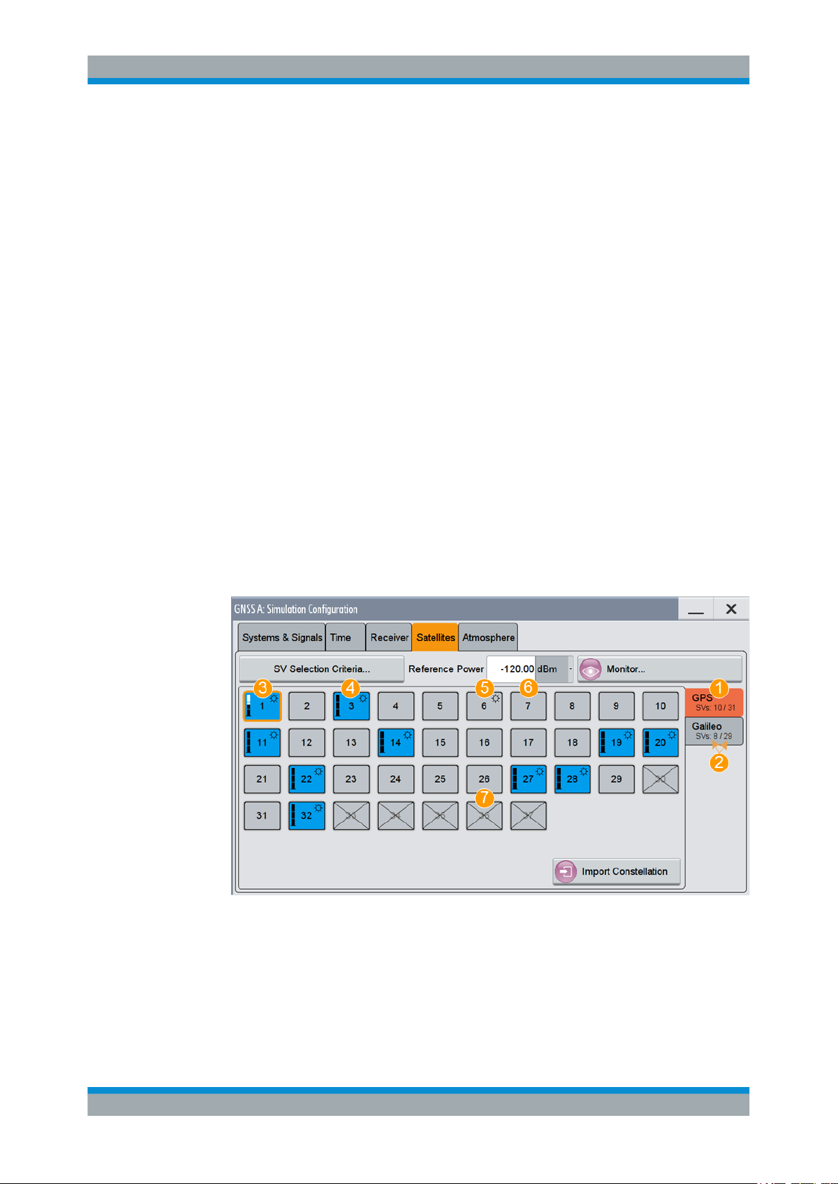
Satellite's ConstellationSatellite Navigation
Satellites Settings
Remote command:
[:SOURce<hw>]:BB:GNSS:SYSTem:GPS:SIGNal:L1Band:CA[:STATe]
on page 213
[:SOURce<hw>]:BB:GNSS:SYSTem:GPS:SIGNal:L1Band:P[:STATe]
on page 213
(etc. for the other GNSS systems)
8.2 Satellites Settings
Access:
1. Select "GNSS > Simulation Configuration" > "Satellites".
In the "Satellite" dialog, you configure the satellites (SV ID) constellation for each
enabled GNSS system.
2. In the "Satellites" dialog, select the GNSS system for that you want to configure
satellites constellation.
3. To configure individual settings per SV, like power offset, used signals and the con-
tent of the navigation message each satellites transmitts, select "SV# > SV Config".
For description, see Chapter 9, "Space Vehicle Configuration", on page 61.
In the "Satellite" dialog, you configure the satellite constellation.
Figure 8-1: Satellites constellation: Understanding the displayed information
1 = Enabled GNSS systems
2 = Number of active and available SVs per GNSS system
3 = Visible and active SV, that uses reduced power level
4 = Visible and active SV, full power level
5 = Visible and inactive SV ("Satellite's Constellation, SV ID" on page 58 = Off)
6 = Not visible and inactive SV
7 = Excluded from the constellation (Present in Constellation = "Off")
54User Manual 1178.6379.02 ─ 01
Page 55

Satellite's ConstellationSatellite Navigation
Satellites Settings
The dialog consists of several tabs, one per activated GNSS Systems ("Systems&Signals > System > On").
Active and visible satellites are indicated with blue color.
The maximum number of the configurable satellites depends on the installed
options and can be additionally defined, see "SV Selection Criteria" on page 55.
Settings
SV Selection Criteria.....................................................................................................55
└ Selection Mode............................................................................................... 55
└ Earth Obscuration References........................................................................56
└ Earth Obscuration Offset................................................................................ 57
└ Number of SVs > Min, Max, Current...............................................................58
Ref. Power.................................................................................................................... 58
Monitor.......................................................................................................................... 58
Satellite's Constellation, SV ID......................................................................................58
└ State (SV ID)...................................................................................................59
└ Power Offset................................................................................................... 59
└ SV Config........................................................................................................60
Import Constellation...................................................................................................... 60
SV Selection Criteria
Access: "GNSS > Simulation Configuration > Satellites > SV Selection Criteria"
Opens the "SV Selection Criteria" dialog, where you set the minimum and maximum
number of satellites that can be activated per GNSS system and to set the satellites'
handover criteria
Selection Mode ← SV Selection Criteria
Sets the criteria used to define the initial satellite constellation and rule applied by the
satellite's handover.
"Visibility Time"
Constellation consists of satellites that are likely to be visible for the
longest time.
"Elevation Angle"
Selected are the satellites with the highest elevation.
Elevation is defined by the Earth Obscuration References and Earth
Obscuration Offset.
55User Manual 1178.6379.02 ─ 01
Page 56

Satellite's ConstellationSatellite Navigation
Satellites Settings
"Manual"
The automatic satellite's constellation configuration is deactivated.
Change the state of an SV ID to change the satellite constellation
manually. Any SV ID, incl. satellites that are currently invisible, can be
activated.
Remote command:
[:SOURce<hw>]:BB:GNSS:SV:SELection:MODE on page 254
Earth Obscuration References ← SV Selection Criteria
Selects how the behavior of earth obscuration is defined. This also defines the horizon,
which is the reference line for applying the elevation mask angle, see Figure 8-2.
Figure 8-2: Impact of the Earth Obscuration References on the area of visible satellites (XY cut)
A = "Local Horizon"
B = "Earth Tangent"
α
= "Earth Obscuration Offset" applied relative to the selected horizon
h = "Receiver > Positioning Configuration > Altitude"
r = Nadir (an imaginary vertical line that connects the location and the center of the earth)
1a = Horizon line for "Altitude = 0 m" (identical for both elevation mask types)
1b = Area of visible satellites (identical for both elevation mask types)
2a = Horizon line for "Altitude = h, km"; the horizon is parallel to the horizon with "Altitude = 0 m"
2b = Area of visible satellites
3a = Horizon lines for "Altitude = h, km"; the horizon lines are tangential to the earth surface
3b = Area of visible satellites
Use the "Signal Monitor" view to observe the current satellite constellation.
The figures in Table 8-3 show the satellite constellations as seen by receiver at an
"Altitude = 200 km" with "Earth Obscuration Offset = 5°". The number of active satellites changes because of the different elevation mask types.
56User Manual 1178.6379.02 ─ 01
Page 57

Satellite's ConstellationSatellite Navigation
Satellites Settings
Table 8-3: Impact of the Earth Obscuration References on the visible satellites
"Earth Obscuration References > Local Horizon" "Earth Obscuration References > Earth Tangent"
"Local Horizon"
The horizon is a horizontal plane that is perpendicular to the nadir.
For locations with attitudes above the sea level, the horizontal plane
is parallel shifted at the selected attitude.
The "Local Horizon" type is suitable, if you simulate receivers located
at low altitude. For example, for pedestrian and automotive application.
"Earth Tangent"
The horizon is the surface of a right circular cone, where:
●
The vertex of the cone is at the receiver position.
●
The cone axis is along the nadir.
●
The cone surface is made of lines that are tangential to the earth
surface.
The "Earth Tangent" type is suitable, if you simulate receivers located
at higher altitude, where satellites with negative elevations are also
visible. A typical example is a GNSS receiver mounted on low earth
orbit (LEO) object.
Remote command:
[:SOURce<hw>]:BB:GNSS:SV:SELection:EOBScuration:REFerence
on page 254
Earth Obscuration Offset ← SV Selection Criteria
Sets the satellite's elevation mask angle. The angle is applied relative to the selected
horizon, see Earth Obscuration References.
Satellites that are below the elevation mask angle are obscured. They are invisible for
the GNSS receiver at the selected location.
Obscured satellites are displayed in the "Signal Monitor" view but not simulated. A test
receiver cannot use obscured satellites for determining its position; it has to search for
satellites with better visibility.
See, for example, the figures in Table 8-3.
57User Manual 1178.6379.02 ─ 01
Page 58

Satellite's ConstellationSatellite Navigation
Satellites Settings
To ensure proper signal analysis, set the parameter "Earth Obscuration Offset" to the
elevation mask of the GNSS receiver under test.
Remote command:
[:SOURce<hw>]:BB:GNSS:SV:SELection:EOBScuration:ANGLe on page 255
Number of SVs > Min, Max, Current ← SV Selection Criteria
Sets the "Min" and "Max" number of satellites per GNSS system that can be included
in the satellite constellation.
"Current" indicates the number of active satellites per GNSS system that are currently
part of the satellite's constellation.
The displayed value resembles the overview information on the side tab of the "Satellites" dialog.
Remote command:
[:SOURce<hw>]:BB:GNSS:SV:SELection:GPS:MIN on page 256
[:SOURce<hw>]:BB:GNSS:SV:SELection:GPS:MAX on page 256
[:SOURce<hw>]:BB:GNSS:SV:SELection:GPS:ACTive? on page 256
see also [:SOURce<hw>]:BB:GNSS:SV:SELection:GPS:AVAilable?
on page 257
(etc. for the other GNSS systems)
Ref. Power
Sets the power level that is used as a reference for the calculation of the power level of
the satellites.
See "About satellite's (SV) power calculation" on page 61.
Remote command:
[:SOURce<hw>]:BB:GNSS:POWer:REFerence on page 264
Monitor
Access the "Simulation Monitor" dialog for real-time display of the major parameters,
like current satellite constellation with SV states and position, receiver position or
movement trajectory, or received satellite power.
See Chapter 5.3, "Simulation Monitor", on page 26.
Satellite's Constellation, SV ID
Indicates the SV IDs included in the current constellation.
= Enabled GNSS systems
1
2 = Number of active and available SVs per GNSS system
3 = Visible and active SV, that uses reduced power level
58User Manual 1178.6379.02 ─ 01
Page 59

Satellite's ConstellationSatellite Navigation
Satellites Settings
4 = Visible and active SV, full power level
5 = Visible and inactive SV ("Satellite's Constellation, SV ID" on page 58 = Off)
6 = Not visible and inactive SV
7 = Excluded from the constellation (Present in Constellation = "Off")
The information is color-coded. Icons provide further information:
●
Blue: active SV ID
●
Gray: Inactive SV ID
●
Sun: Visible SV ID
●
Cross out: SV ID is excluded form the constellation, for example if "SV ID > SV
Config" > Present in Constellation > "Off"
●
Power bar: Reduced height indicates enabled power offset i.e the signal of the SV
ID is transmitted with less power than the value indicated as "Configurable Nav.
Message"
The blocks are interactive. Select an SV ID to access further settings for changing its
state, enabling power offset of configuring the orbit simulation and navigation message
parameters.
Remote command:
[:SOURce<hw>]:BB:GNSS:SVID:GPS:LIST? on page 257
[:SOURce<hw>]:BB:GNSS:SVID<ch>:GPS:HEALthy? on page 257
(etc. for the other GNSS systems)
State (SV ID) ← Satellite's Constellation, SV ID
Changes the SV ID state on-the-fly.
Per default, only visible satellites can be included in the constellation. SV ID for that
Present in Constellation > "Off" cannot be activated.
Tip: Pressing the ON/OFF TOGGLE key has the same effect on the selected SV ID.
To enable any SV ID, set "Satellites > SV Selection Criteria > Selection Mode > Man-
ual".
Remote command:
[:SOURce<hw>]:BB:GNSS:SVID<ch>:GPS:STATe on page 263
(etc. for the other GNSS systems)
Power Offset ← Satellite's Constellation, SV ID
Reduces the signal of the selected SV ID by the defined value.
59User Manual 1178.6379.02 ─ 01
Page 60

Satellite's ConstellationSatellite Navigation
Satellites Settings
This is a global power offset parameter for a satellite. It affects the power level of all
signal components of a given satellite, see "About satellite's (SV) power calculation"
on page 61.
Power changes are applied on-the-fly.
Remote command:
[:SOURce<hw>]:BB:GNSS:SVID<ch>:GPS:POWer:OFFSet on page 264
(etc. for the other GNSS systems)
SV Config ← Satellite's Constellation, SV ID
Access a dialog with further settings for configuring the orbit simulation and navigation
message parameters.
See:
●
Chapter 9, "Space Vehicle Configuration", on page 61
●
Chapter 12, "Perturbations and Errors Simulation", on page 101
Import Constellation
Opens the "Import Constellation" dialog, see Chapter 17, "Loading Historical Data",
on page 190.
60User Manual 1178.6379.02 ─ 01
Page 61

Space Vehicle ConfigurationSatellite Navigation
9 Space Vehicle Configuration
About satellite's (SV) power calculation
In R&S SMW, you define the power level of the individual satellites or their signals and
the power level at the RF output is calculated automatically. All power levels are set
relative to a configurable reference level. By changing this level you boost or
decrease the signal power at the R&S SMW outputs, while maintaining the power ratio
between the satellites, their signals and, if enabled, the multi-path echoes.
Absolute SV power
The absolute SV power for a given signal P
P
●
●
= P
SV,signal
P
Ref
P
SV,offset
+ P
Ref
is the reference power level, as set with the parameter Ref. Power
is the global power offset of the satellite, as set with the parameter Power
SV,offset
+ P
Signal,offset
+ P
PathLoss
SV,signal
is calculated as follows:
+ P
AntPat
, where:
Offset
●
P
Signal,offset
is signal-specific power offset, as set with the parameter Signal Power
Offset
The value reflects the differences between the signals and the frequency bands.
●
P
is the free space path-loss over the satellite to receiver distance (range),
PathLoss
included if Add Power Path-Loss > "On".
See "Free space path-loss power" on page 61.
●
P
is the power gain of the antenna, calculated automatically, depending on the
AntPat
selected body mask
See Chapter 10.6, "Antenna Configuration Settings", on page 87.
Free space path-loss power
P
is the free space path-loss over the satellite to receiver distance (range), cal-
PathLoss
culated as follows:
P
●
= 20log10(R0/R), where:
PathLoss
R0 = √(R
Orbit,SV
2
- r2)
R0 is the reference range, equal to the range of a receiver on the ground to an SV
at 90° elevation
●
R is the receiver to satellite range.
0
61User Manual 1178.6379.02 ─ 01
Page 62

Figure 9-1: Free space path-loss calculation
SV0= Reference space vehicle
R0= Reference range
SV = Space vehicle
R = Range between the SV and the receiver
r = Earth's radius
Absolute multi-path echo power
Space Vehicle ConfigurationSatellite Navigation
Power Settings
The absolute power of an echo for a given signal P
P
●
●
9.1 Power Settings
SV,echo
P
SV,signal
P
Echo,signal
= P
SV,signal
+ P
Echo,signal
is the absolute satellite's power
is the power offset per echo, as set with the parameter Power Offset.
Access:
1. Select "GNSS > Simulation Configuration > Satellites".
2. Set the "Reference Power".
All power values are set relative to the reference power.
3. Select the GNSS system for that you want to change the satellite's power settings,
for example GPS.
4. Select "SV# > SV Config".
5. In the "SV Configuration" dialog, select "Signals Configuration".
, where:
is calculated as follows:
SV,echo
6. Select "Add Power Path-Loss > On" to account for the free-space attenuation.
7. Set a "Power Offset" to additionally reduce the signal power of the satellite.
8. In dual-band or multi-signal configurations, set a "Signal Power Offset" to account
for the power relation between the signals.
9. To apply the power settings of the current satellite to other SV ID, select for example "SV-ID = 11" and "Copy Power Settings To".
62User Manual 1178.6379.02 ─ 01
Page 63

Space Vehicle ConfigurationSatellite Navigation
Power Settings
Figure 9-2: Power settings: understanding the displayed information
1 = Decreases the SV signal power and thus the power of all signals of this SV. SV "Power Offset" is
set relative to the Ref. Power
2 = Boosts or decreases the power of the individual signal components. Power offsets are set relative to
the Ref. Power + "Power Offset"
Available power settings depend on the GNSS system and selected RF band.
For information on how these settings affect the SV power, see "About satellite's
(SV) power calculation" on page 61.
10. To simulate multi-path effects:
For more information, see Chapter 10.8, "Static Multipath", on page 92.
a) Select "Simulation Configuration > Receiver > Environmental Model = Static
Multipath".
b) Select "Environmental Model"
c) Set for example: "Number of Echoes = 1", "Echo 1 > Init. Code Phase = 300
m", "Power Offset = -10 dB".
11. Select "GNSS > Monitor > Satellites > Power View" to observe the power levels of
all satellites at a glance.
63User Manual 1178.6379.02 ─ 01
Page 64
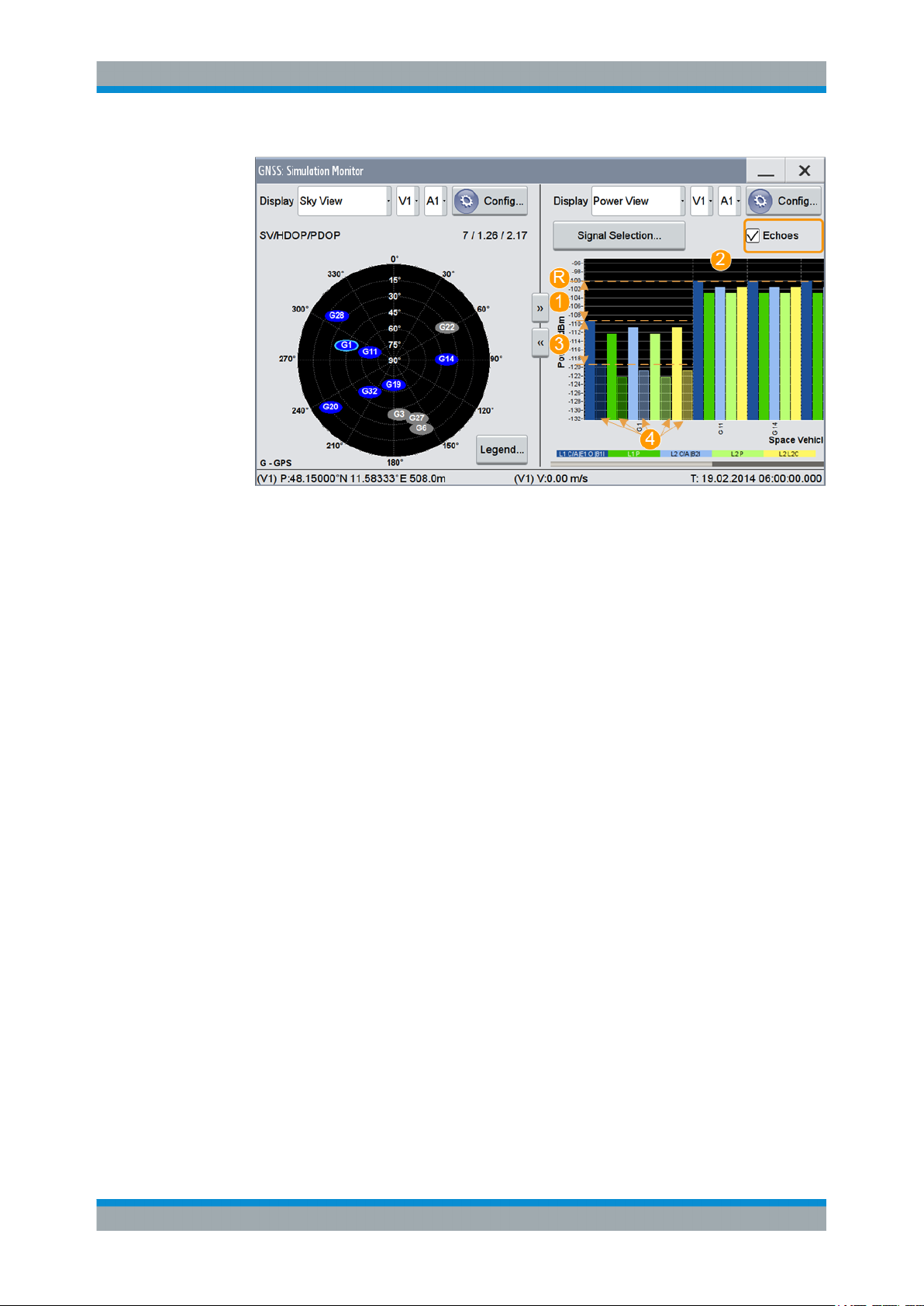
Space Vehicle ConfigurationSatellite Navigation
Figure 9-3: Power View: understanding the displayed information
Power Settings
R = Ref. Power= -100 dB
1 = "SV ID 1 > Power Offset = -10 dB"
2 = "Signal Power Offsets", e.g. C/A = 0 dB and P = - 3dB; the same power relation is observed SVs
with or without Power Offset and for the multi-path echoes
3 = "SV ID 1 > Echo 1 > Power Offset = -10 dB"
4 = One echo per signal ("Number of Echoes = 1"); displayed if "Echoes = On"
12. Load and enable body mask files to visualize the effect of antennas on the power.
For more information, see Chapter 10.6, "Antenna Configuration Settings",
on page 87.
The remote commands required to define these settings are described in:
● Chapter 19.10, "Signals and Power Configuration per Satellite", on page 259
● Chapter 19.7, "Static Multipath Configuration", on page 237.
Settings
State (SV ID).................................................................................................................64
Present in Constellation................................................................................................ 65
Power Offset................................................................................................................. 65
Add Power Path-Loss................................................................................................... 65
Frequency Number....................................................................................................... 65
SV signal configuration table.........................................................................................66
└ Signal Power Offset........................................................................................ 66
Copy Power Settings to,SV-ID......................................................................................66
State (SV ID)
Changes the SV ID state on-the-fly.
Per default, only visible satellites can be included in the constellation. SV ID for that
Present in Constellation > "Off" cannot be activated.
Tip: Pressing the ON/OFF TOGGLE key has the same effect on the selected SV ID.
64User Manual 1178.6379.02 ─ 01
Page 65

Space Vehicle ConfigurationSatellite Navigation
Power Settings
To enable any SV ID, set "Satellites > SV Selection Criteria > Selection Mode > Manual".
Remote command:
[:SOURce<hw>]:BB:GNSS:SVID<ch>:GPS:STATe on page 263
(etc. for the other GNSS systems)
Present in Constellation
If disabled, the SV ID is excluded from the currents constellation. The SV ID is automatically deactivated ("SV ID > State = Off").
In the "Satellites" dialog, SV IDs that are excluded from the constellation are displayed
in gray color and are crossed out.
To reactivate such satellite, set "Present in Constellation > On" and activate it ("State >
On")
Remote command:
[:SOURce<hw>]:BB:GNSS:SVID<ch>:GPS:PRESent on page 263
(etc. for the other GNSS systems)
Power Offset
Reduces the signal of the selected SV ID by the defined value.
This is a global power offset parameter for a satellite. It affects the power level of all
signal components of a given satellite, see "About satellite's (SV) power calculation"
on page 61.
Power changes are applied on-the-fly.
Remote command:
[:SOURce<hw>]:BB:GNSS:SVID<ch>:GPS:POWer:OFFSet on page 264
(etc. for the other GNSS systems)
Add Power Path-Loss
In "Test Mode = Navigation", enable this parameter to account for the free space
attenuation and simulate real-world conditions.
The power of the SV ID signals is reduced automatically. The power path-loss is calculated depending on the current satellite's orbit and the distance (range) between the
satellite and the receiver's position on the Earth, see "Free space path-loss power"
on page 61.
To observe the effect, select the "Monitor > Display > Power View", see Chapter 5.3,
"Simulation Monitor", on page 26.
Remote command:
[:SOURce<hw>]:BB:GNSS:SVID<ch>:GPS:POWer:PLOSs on page 264
(etc. for the other GNSS systems)
Frequency Number
For GLONASS satellites, indicates the frequency number of the subcarrier used to
modulate the GLONASS satellite.
If "Nav Msg Type = NAV", the frequency number is retrieved from the imported configuration file.
65User Manual 1178.6379.02 ─ 01
Page 66

Space Vehicle ConfigurationSatellite Navigation
Modulation Control Settings
The value is configurable, if arbitrary data is used, e.g. "Nav Msg Control = Edit" and
"Nav Msg Type = All 0".
Remote command:
[:SOURce<hw>]:BB:GNSS:SVID<ch>:GLONass:FNUMber on page 266
SV signal configuration table
Table with one or more rows, one row per enabled signal ("Simulation Configuration >
Systems&Signals" > Signals).
Signal Power Offset ← SV signal configuration table
Adds power offset for the selected signal.
If more than one signal or bands are activated, the power relation between the signals
and between the frequency bands is set automatically, as specified for the GNSS system. You can change these default values.
Signal-specific power offset values are set relative to the satellites power level, see
"About satellite's (SV) power calculation" on page 61.
Remote command:
[:SOURce<hw>]:BB:GNSS:SVID<ch>:GPS:SIGNal:L1Band:CA:POWer:OFFset
on page 265
[:SOURce<hw>]:BB:GNSS:SVID<ch>:GPS:SIGNal:L1Band:P:POWer:OFFset
on page 265
(etc. for the other GNSS systems)
Copy Power Settings to,SV-ID
Applies the power settings of the current satellite to the selected or to all SV-IDs of the
same GNSS system.
The following settings are considered:
●
Power Offset
●
Add Power Path-Loss
●
Signal Power Offset
Remote command:
[:SOURce<hw>]:BB:GNSS:SVID<ch>:GPS:POWer:COPY:SVID on page 265
[:SOURce<hw>]:BB:GNSS:SVID<ch>:GPS:POWer:COPY:EXECute on page 266
(etc. for the other GNSS systems)
9.2 Modulation Control Settings
Access:
1. Select "GNSS > Simulation Configuration > Signals&Systems".
2. Enable the GNSS system for that you want to control the signal modulation, for
example:
a) "System > GLONASS > On"
b) "System > Galileo > On"
66User Manual 1178.6379.02 ─ 01
Page 67

Space Vehicle ConfigurationSatellite Navigation
Modulation Control Settings
3. Select "GNSS > Simulation Configuration > Satellites".
4. Select "GLONASS > SV# > SV Config".
5. In the "SV Configuration" dialog, select "Signals Configuration".
6. To generate a continuous wave signal, send on the GLONASS frequency, select:
a) "Primary Code > Off"
b) "Nav. Msg. Control > Off"
c) "Meander Sequence > Off"
d) "Time Sequence > Off"
7. For a Galileo satellite, you achieve the same effect as follows:
a) "Primary Code > Off"
b) "Secondary Code > Off"
c) "Nav. Msg. Control > Off"
8. To apply the modulation control settings of the current satellite to other SV ID,
select for example "SV-ID = All" and "Copy Modulation Control To"
Available modulation control settings depend on the GNSS system and selected
RF band.
See also:
● Chapter 19.10, "Signals and Power Configuration per Satellite", on page 259
Settings
SV signal configuration table.........................................................................................68
└ Signal State.....................................................................................................68
└ Signal Component.......................................................................................... 68
└ Primary Code..................................................................................................68
└ Seconadry Code............................................................................................. 68
└ Nav Msg Control............................................................................................. 69
└ Nav Msg Type, Pattern, Data List...................................................................69
└ Nav Msg Content, Config................................................................................70
67User Manual 1178.6379.02 ─ 01
Page 68

Space Vehicle ConfigurationSatellite Navigation
Modulation Control Settings
└ Meander Sequence.........................................................................................70
└ Time Sequence...............................................................................................70
Copy Modulation Control Settings to,SV-ID..................................................................70
SV signal configuration table
Table with one or more rows, one row per enabled signal ("Simulation Configuration >
Systems&Signals" > Signals).
Signal State ← SV signal configuration table
Activates the selected signal.
The available signals depend on GNSS system and the configuration in the Sys-
tems&Signals dialog.
At least on signal has to be activated per satellite. Activate another signal to deactivate
a particular signal, if it is the only one active at that moment.
Remote command:
[:SOURce<hw>]:BB:GNSS:SVID<ch>:GPS:SIGNal:L1Band:CA[:STATe]
on page 267
[:SOURce<hw>]:BB:GNSS:SVID<ch>:GPS:SIGNal:L1Band:P[:STATe]
on page 267
(etc. for the other GNSS systems)
Signal Component ← SV signal configuration table
Indicates the signal content (data only or data and pilot).
The information is retrieved automatically from the selected simulation data source file.
Signal components depend on the signal, the frequency band and the GNSS system.
Remote command:
n.a.
Primary Code ← SV signal configuration table
Defines if the primary code is used to spread the data and pilot components.
If your interference tests require the generation of a continuous wave signal send on
the same frequency as a specific SV, set "Primary Code > Off" and "Nav Msg Control >
Off".
Remote command:
[:SOURce<hw>]:BB:GNSS:SVID<ch>:GPS:SIGNal:L1Band:CA:PILot:
PCODe[:STATe] on page 268
[:SOURce<hw>]:BB:GNSS:SVID<ch>:GPS:SIGNal:L1Band:P:PILot:PCODe[:
STATe] on page 268
(etc. for the other GNSS systems)
Seconadry Code ← SV signal configuration table
Enables the secondary code in the pilot channel of Galileo, or in the D1 navigation
message for BeiDou.
68User Manual 1178.6379.02 ─ 01
Page 69

Space Vehicle ConfigurationSatellite Navigation
Modulation Control Settings
Remote command:
[:SOURce<hw>]:BB:GNSS:SVID<ch>:GALileo:SIGNal:L1Band:E1OS:DATA:
SCODe[:STATe] on page 269
[:SOURce<hw>]:BB:GNSS:SVID<ch>:GALileo:SIGNal:L1Band:E1OS:PILot:
SCODe[:STATe] on page 269
(etc. for the other GNSS systems)
Nav Msg Control ← SV signal configuration table
Defines whether the navigation message parameters can be changed or not.
"On/Edit"
"Off"
"Auto"
Remote command:
"Test Mode = Navigation"
[:SOURce<hw>]:BB:GNSS:SVID<ch>:GPS:SIGNal:L1Band:CA:DATA:
NMESsage:CONTrol on page 269
[:SOURce<hw>]:BB:GNSS:SVID<ch>:GPS:SIGNal:L1Band:P:DATA:
NMESsage:CONTrol on page 269
"Test Mode = Tracking"
[:SOURce<hw>]:BB:GNSS:SVID<ch>:GPS:SIGNal:L1Band:CA:DATA:
NMESsage[:STATe] on page 353
[:SOURce<hw>]:BB:GNSS:SVID<ch>:GPS:SIGNal:L1Band:P:DATA:
NMESsage[:STATe] on page 353
(etc. for the other GNSS systems)
Enables configuration of the navigation message parameters.
Navigation message content of the SBAS SV is set automatically. To
enable the navigation message for configuration, set "Satellites" >
Error Correction Mode = "Replay Historical Data (and Sync Atmos-
phere& SV Errors)".
If "Satellites" > Error Correction Mode = "Replay Historical Data and
Sync Atmosphere& SV Errors", the navigation message content of all
other GNSS systems than SBAS is configured automatically. Editing
is not possible.
Navigation message is disabled.
In Test Mode = "Navigation", the navigation message parameters are
adjusted automatically.
Nav Msg Type, Pattern, Data List ← SV signal configuration table
Sets the data source used for the generation of the navigation message.
"LNAV/CNAV/INAV/DNAV/NAV"
The navigation message parameters are "real" since they are
retrieved from the loaded simulation data source file, see Import Con-
stellation.
To change the automatically filled in values, select:
●
Nav Msg Control = "Edit"
●
Nav Msg Content > Config.
Remote command:
[:SOURce<hw>]:BB:GNSS:SVID<ch>:GPS:SIGNal:L1Band:CA:DATA:
NMESsage:TYPE on page 270
(etc. for the other GNSS systems)
69User Manual 1178.6379.02 ─ 01
Page 70

Space Vehicle ConfigurationSatellite Navigation
Simulated Orbit and Orbit Perturbation Settings
Nav Msg Content, Config ← SV signal configuration table
Opens the "Navigation Message" dialog, where you can observe the navigation message parameter and if enabled, change them.
See Chapter 12, "Perturbations and Errors Simulation", on page 101.
Meander Sequence ← SV signal configuration table
Enables meandering, i.e. doubling the data rate of a GLONASS satellite navigation signal.
Remote command:
[:SOURce<hw>]:BB:GNSS:SVID<ch>:GLONass:SIGNal:L1Band:CA:DATA:
MEANdering[:STATe] on page 271
[:SOURce<hw>]:BB:GNSS:SVID<ch>:GLONass:SIGNal:L2Band:CA:DATA:
MEANdering[:STATe] on page 271
Time Sequence ← SV signal configuration table
Enables the time signal component of GLONASS signals.
Remote command:
[:SOURce<hw>]:BB:GNSS:SVID<ch>:GLONass:SIGNal:L1Band:CA:DATA:
TSEQuence[:STATe] on page 271
[:SOURce<hw>]:BB:GNSS:SVID<ch>:GLONass:SIGNal:L2Band:CA:DATA:
TSEQuence[:STATe] on page 271
Copy Modulation Control Settings to,SV-ID
Applies the power settings of the current satellite to the selected or to all SV-IDs of the
same GNSS system.
The following settings are considered:
●
Signal State
●
Primary Code
●
Seconadry Code
●
Nav Msg Control
●
Nav Msg Type, Pattern, Data List
●
Meander Sequence
●
Time Sequence
Remote command:
[:SOURce<hw>]:BB:GNSS:SVID<ch>:GPS:MCONtrol:COPY:SVID on page 271
[:SOURce<hw>]:BB:GNSS:SVID<ch>:GPS:MCONtrol:COPY:EXECute
on page 272
(etc. for the other GNSS systems)
9.3 Simulated Orbit and Orbit Perturbation Settings
Access:
1. Select "GNSS > Simulation Configuration > Satellites".
70User Manual 1178.6379.02 ─ 01
Page 71

Space Vehicle ConfigurationSatellite Navigation
Simulated Orbit and Orbit Perturbation Settings
2. Select the GNSS system for that you want to configure satellites constellation, for
example GPS.
3. Select "SV# > SV Config".
4. In the "SV Configuration" dialog, select "Simulated Orbit > Orbit" or "Simulated
Orbit > Orbit Perturbation".
Available navigation message parameters depend on the GNSS system.
Settings
Ground Track................................................................................................................ 71
GPS SV.........................................................................................................................71
└ Simulated Orbit............................................................................................... 72
└ Orbit Perturbation............................................................................................72
Galileo SV..................................................................................................................... 73
└ Simulated Orbit............................................................................................... 73
└ Orbit Perturbation............................................................................................74
GLONASS SV...............................................................................................................74
└ Simulated Orbit............................................................................................... 74
BeiDou SV.....................................................................................................................75
└ Simulated Orbit............................................................................................... 75
└ Orbit Perturbation............................................................................................75
QZSS SV.......................................................................................................................76
└ Simulated Orbit............................................................................................... 76
└ Orbit Perturbation............................................................................................77
Ground Track
Displays a plot of the trajectory of the selected satellite.
GPS SV
Comprises the navigation message parameters, specific to and common for all GPS
satellites.
71User Manual 1178.6379.02 ─ 01
Page 72

Space Vehicle ConfigurationSatellite Navigation
Simulated Orbit and Orbit Perturbation Settings
Simulated Orbit ← GPS SV
Comprises the navigation message parameters, specific to and common for all GPS
satellites.
Parameter Remote command:
Reference Week [:SOURce<hw>]:BB:GNSS:SVID<ch>:GPS:
SIMulated:ORBit:WNOE on page 286
Reference Time of Week [:SOURce<hw>]:BB:GNSS:SVID<ch>:GPS:
SIMulated:ORBit:TOE on page 286
Square Root of Semi-Major Axis - A
1/2
[:SOURce<hw>]:BB:GNSS:SVID<ch>:GPS:
SIMulated:ORBit:SQRA on page 287
Eccentricity - e [:SOURce<hw>]:BB:GNSS:SVID<ch>:GPS:
SIMulated:ORBit:ECCentricity on page 288
Inclination Angle - i
0
[:SOURce<hw>]:BB:GNSS:SVID<ch>:GPS:
SIMulated:ORBit:IZERo on page 288
Longitude of Ascending Node - Ω
0
[:SOURce<hw>]:BB:GNSS:SVID<ch>:GPS:
SIMulated:ORBit:OZERo on page 288
Argument of Perigee - ω [:SOURce<hw>]:BB:GNSS:SVID<ch>:GPS:
SIMulated:ORBit:OMEGa on page 289
Mean Anomaly - M
0
[:SOURce<hw>]:BB:GNSS:SVID<ch>:GPS:
SIMulated:ORBit:MZERo on page 289
Rate of Inclination Angle - i' [:SOURce<hw>]:BB:GNSS:SVID<ch>:GPS:
SIMulated:ORBit:IDOT on page 289
Rate of Right Ascension - Ω' [:SOURce<hw>]:BB:GNSS:SVID<ch>:GPS:
SIMulated:ORBit:ODOT on page 289
Mean Motion Difference - Δ
n
[:SOURce<hw>]:BB:GNSS:SVID<ch>:GPS:
SIMulated:ORBit:NDELta on page 290
Orbit Perturbation ← GPS SV
Comprises the navigation message parameters, specific to and common for all GPS
satellites.
Parameter Remote command:
Cosine Difference of Latitude - C
uc
[:SOURce<hw>]:BB:GNSS:SVID<ch>:GPS:
SIMulated:ORBit:CUC on page 290
Sine Difference of Latitude - C
us
[:SOURce<hw>]:BB:GNSS:SVID<ch>:GPS:
SIMulated:ORBit:CUS on page 290
Cosine Difference of Orbital Radius - C
rc
[:SOURce<hw>]:BB:GNSS:SVID<ch>:GPS:
SIMulated:ORBit:CRC on page 291
Sine Difference of Orbital Radius - C
rs
[:SOURce<hw>]:BB:GNSS:SVID<ch>:GPS:
SIMulated:ORBit:CRS on page 291
72User Manual 1178.6379.02 ─ 01
Page 73

Space Vehicle ConfigurationSatellite Navigation
Simulated Orbit and Orbit Perturbation Settings
Parameter Remote command:
Cosine Difference of Inclination - C
ic
[:SOURce<hw>]:BB:GNSS:SVID<ch>:GPS:
SIMulated:ORBit:CIC on page 291
Sine Difference of Inclination - C
is
[:SOURce<hw>]:BB:GNSS:SVID<ch>:GPS:
SIMulated:ORBit:CIS on page 291
Galileo SV
Comprises the navigation message parameters, specific to and common for all Galileo
satellites.
Simulated Orbit ← Galileo SV
Comprises the navigation message parameters, specific to and common for all Galileo
satellites.
Parameter Remote command:
Reference Week [:SOURce<hw>]:BB:GNSS:SVID<ch>:
GALileo:SIMulated:ORBit:WNOE on page 286
Reference Time of Week [:SOURce<hw>]:BB:GNSS:SVID<ch>:
GALileo:SIMulated:ORBit:TOE on page 286
Square Root of Semi-Major Axis - A
1/2
Eccentricity - e [:SOURce<hw>]:BB:GNSS:SVID<ch>:
[:SOURce<hw>]:BB:GNSS:SVID<ch>:
GALileo:SIMulated:ORBit:SQRA on page 287
GALileo:SIMulated:ORBit:ECCentricity
on page 287
Inclination Angle - i
0
[:SOURce<hw>]:BB:GNSS:SVID<ch>:
GALileo:SIMulated:ORBit:IZERo
on page 288
Longitude of Ascending Node - Ω
0
[:SOURce<hw>]:BB:GNSS:SVID<ch>:
GALileo:SIMulated:ORBit:OZERo
on page 288
Argument of Perigee - ω [:SOURce<hw>]:BB:GNSS:SVID<ch>:
GALileo:SIMulated:ORBit:OMEGa
on page 288
Mean Anomaly - M
0
[:SOURce<hw>]:BB:GNSS:SVID<ch>:
GALileo:SIMulated:ORBit:MZERo
on page 289
Rate of Inclination Angle - i' [:SOURce<hw>]:BB:GNSS:SVID<ch>:
GALileo:SIMulated:ORBit:IDOT on page 289
Rate of Right Ascension - Ω' [:SOURce<hw>]:BB:GNSS:SVID<ch>:
GALileo:SIMulated:ORBit:ODOT on page 289
Mean Motion Difference - Δ
n
[:SOURce<hw>]:BB:GNSS:SVID<ch>:
GALileo:SIMulated:ORBit:NDELta
on page 290
73User Manual 1178.6379.02 ─ 01
Page 74

Space Vehicle ConfigurationSatellite Navigation
Simulated Orbit and Orbit Perturbation Settings
Orbit Perturbation ← Galileo SV
Comprises the navigation message parameters, specific to and common for all Galileo
satellites.
Parameter Remote command:
Cosine Difference of Latitude - C
uc
[:SOURce<hw>]:BB:GNSS:SVID<ch>:
GALileo:SIMulated:ORBit:CUC on page 290
Sine Difference of Latitude - C
us
[:SOURce<hw>]:BB:GNSS:SVID<ch>:
GALileo:SIMulated:ORBit:CUS on page 290
Cosine Difference of Orbital Radius - C
rc
[:SOURce<hw>]:BB:GNSS:SVID<ch>:
GALileo:SIMulated:ORBit:CRC on page 291
Sine Difference of Orbital Radius - C
rs
[:SOURce<hw>]:BB:GNSS:SVID<ch>:
GALileo:SIMulated:ORBit:CRS on page 291
Cosine Difference of Inclination - C
ic
[:SOURce<hw>]:BB:GNSS:SVID<ch>:
GALileo:SIMulated:ORBit:CIC on page 291
Sine Difference of Inclination - C
is
[:SOURce<hw>]:BB:GNSS:SVID<ch>:
GALileo:SIMulated:ORBit:CIS on page 291
GLONASS SV
Comprises the navigation message parameters, specific to and common for all GLONASS satellites.
Simulated Orbit ← GLONASS SV
Comprises the navigation message parameters, specific to and common for all GLONASS satellites.
Parameter Remote command:
Reference Date [:SOURce<hw>]:BB:GNSS:SVID<ch>:GLONass:SIMulated:ORBit:DATE
on page 286
Reference Time [:SOURce<hw>]:BB:GNSS:SVID<ch>:GLONass:SIMulated:ORBit:TIME
on page 287
X
n
[:SOURce<hw>]:BB:GNSS:SVID<ch>:GLONass:SIMulated:ORBit:XN
on page 285
Y
n
[:SOURce<hw>]:BB:GNSS:SVID<ch>:GLONass:SIMulated:ORBit:YN
on page 285
Z
n
[:SOURce<hw>]:BB:GNSS:SVID<ch>:GLONass:SIMulated:ORBit:ZN
on page 285
X'
n
[:SOURce<hw>]:BB:GNSS:SVID<ch>:GLONass:SIMulated:ORBit:XDN
on page 285
Y'
n
[:SOURce<hw>]:BB:GNSS:SVID<ch>:GLONass:SIMulated:ORBit:YDN
on page 285
Z'
n
[:SOURce<hw>]:BB:GNSS:SVID<ch>:GLONass:SIMulated:ORBit:ZDN
on page 285
X''
n
[:SOURce<hw>]:BB:GNSS:SVID<ch>:GLONass:SIMulated:ORBit:XDDN
on page 285
74User Manual 1178.6379.02 ─ 01
Page 75

Parameter Remote command:
Space Vehicle ConfigurationSatellite Navigation
Simulated Orbit and Orbit Perturbation Settings
Y''
Z''
n
n
[:SOURce<hw>]:BB:GNSS:SVID<ch>:GLONass:SIMulated:ORBit:YDDN
on page 285
[:SOURce<hw>]:BB:GNSS:SVID<ch>:GLONass:SIMulated:ORBit:ZDDN
on page 285
BeiDou SV
Comprises the navigation message parameters, specific to and common for all BeiDou
satellites.
Simulated Orbit ← BeiDou SV
Comprises the navigation message parameters, specific to and common for all BeiDou
satellites.
Parameter Remote command:
Reference Week [:SOURce<hw>]:BB:GNSS:SVID<ch>:BEIDou:
SIMulated:ORBit:WNOE on page 286
Reference Time of Week [:SOURce<hw>]:BB:GNSS:SVID<ch>:BEIDou:
SIMulated:ORBit:TOE on page 286
Square Root of Semi-Major Axis - A
Eccentricity - e [:SOURce<hw>]:BB:GNSS:SVID<ch>:BEIDou:
1/2
[:SOURce<hw>]:BB:GNSS:SVID<ch>:BEIDou:
SIMulated:ORBit:SQRA on page 287
SIMulated:ORBit:ECCentricity on page 288
Inclination Angle - i
Longitude of Ascending Node - Ω
Argument of Perigee - ω [:SOURce<hw>]:BB:GNSS:SVID<ch>:BEIDou:
Mean Anomaly - M
Rate of Inclination Angle - i' [:SOURce<hw>]:BB:GNSS:SVID<ch>:BEIDou:
Rate of Right Ascension - Ω' [:SOURce<hw>]:BB:GNSS:SVID<ch>:BEIDou:
Mean Motion Difference - Δ
0
0
0
n
[:SOURce<hw>]:BB:GNSS:SVID<ch>:BEIDou:
SIMulated:ORBit:IZERo on page 288
[:SOURce<hw>]:BB:GNSS:SVID<ch>:BEIDou:
SIMulated:ORBit:OZERo on page 288
SIMulated:ORBit:OMEGa on page 289
[:SOURce<hw>]:BB:GNSS:SVID<ch>:BEIDou:
SIMulated:ORBit:MZERo on page 289
SIMulated:ORBit:IDOT on page 289
SIMulated:ORBit:ODOT on page 289
[:SOURce<hw>]:BB:GNSS:SVID<ch>:BEIDou:
SIMulated:ORBit:NDELta on page 290
Orbit Perturbation ← BeiDou SV
Comprises the navigation message parameters, specific to and common for all BeiDou
satellites.
75User Manual 1178.6379.02 ─ 01
Page 76

Space Vehicle ConfigurationSatellite Navigation
Simulated Orbit and Orbit Perturbation Settings
Parameter Remote command:
Cosine Difference of Latitude - C
uc
[:SOURce<hw>]:BB:GNSS:SVID<ch>:BEIDou:
SIMulated:ORBit:CUC on page 290
Sine Difference of Latitude - C
us
[:SOURce<hw>]:BB:GNSS:SVID<ch>:BEIDou:
SIMulated:ORBit:CUS on page 290
Cosine Difference of Orbital Radius - C
rc
[:SOURce<hw>]:BB:GNSS:SVID<ch>:BEIDou:
SIMulated:ORBit:CRC on page 291
Sine Difference of Orbital Radius - C
rs
[:SOURce<hw>]:BB:GNSS:SVID<ch>:BEIDou:
SIMulated:ORBit:CRS on page 291
Cosine Difference of Inclination - C
ic
[:SOURce<hw>]:BB:GNSS:SVID<ch>:BEIDou:
SIMulated:ORBit:CIC on page 291
Sine Difference of Inclination - C
is
[:SOURce<hw>]:BB:GNSS:SVID<ch>:BEIDou:
SIMulated:ORBit:CIS on page 291
QZSS SV
Comprises the navigation message parameters, specific to and common for all QZSS
satellites.
Simulated Orbit ← QZSS SV
Comprises the navigation message parameters, specific to and common for all QZSS
satellites.
Parameter Remote command:
Reference Week [:SOURce<hw>]:BB:GNSS:SVID<ch>:QZSS:
SIMulated:ORBit:WNOE on page 286
Reference Time of Week [:SOURce<hw>]:BB:GNSS:SVID<ch>:QZSS:
SIMulated:ORBit:TOE on page 286
Square Root of Semi-Major Axis - A
1/2
[:SOURce<hw>]:BB:GNSS:SVID<ch>:QZSS:
SIMulated:ORBit:SQRA on page 287
Eccentricity - e [:SOURce<hw>]:BB:GNSS:SVID<ch>:QZSS:
SIMulated:ORBit:ECCentricity on page 287
Inclination Angle - i
0
[:SOURce<hw>]:BB:GNSS:SVID<ch>:QZSS:
SIMulated:ORBit:IZERo on page 288
Longitude of Ascending Node - Ω
0
[:SOURce<hw>]:BB:GNSS:SVID<ch>:QZSS:
SIMulated:ORBit:OZERo on page 288
Argument of Perigee - ω [:SOURce<hw>]:BB:GNSS:SVID<ch>:QZSS:
SIMulated:ORBit:OMEGa on page 288
Mean Anomaly - M
0
[:SOURce<hw>]:BB:GNSS:SVID<ch>:QZSS:
SIMulated:ORBit:MZERo on page 289
Rate of Inclination Angle - i' [:SOURce<hw>]:BB:GNSS:SVID<ch>:QZSS:
SIMulated:ORBit:IDOT on page 289
76User Manual 1178.6379.02 ─ 01
Page 77

Space Vehicle ConfigurationSatellite Navigation
Simulated Clock Settings
Parameter Remote command:
Rate of Right Ascension - Ω' [:SOURce<hw>]:BB:GNSS:SVID<ch>:QZSS:
SIMulated:ORBit:ODOT on page 289
Mean Motion Difference - Δ
n
[:SOURce<hw>]:BB:GNSS:SVID<ch>:QZSS:
SIMulated:ORBit:NDELta on page 290
Orbit Perturbation ← QZSS SV
Comprises the navigation message parameters, specific to and common for all QZSS
satellites.
Parameter Remote command:
Cosine Difference of Latitude - C
Sine Difference of Latitude - C
Cosine Difference of Orbital Radius - C
Sine Difference of Orbital Radius - C
Cosine Difference of Inclination - C
Sine Difference of Inclination - C
uc
us
rs
ic
is
rc
[:SOURce<hw>]:BB:GNSS:SVID<ch>:QZSS:
SIMulated:ORBit:CUC on page 290
[:SOURce<hw>]:BB:GNSS:SVID<ch>:QZSS:
SIMulated:ORBit:CUS on page 290
[:SOURce<hw>]:BB:GNSS:SVID<ch>:QZSS:
SIMulated:ORBit:CRC on page 291
[:SOURce<hw>]:BB:GNSS:SVID<ch>:QZSS:
SIMulated:ORBit:CRS on page 291
[:SOURce<hw>]:BB:GNSS:SVID<ch>:QZSS:
SIMulated:ORBit:CIC on page 291
[:SOURce<hw>]:BB:GNSS:SVID<ch>:QZSS:
SIMulated:ORBit:CIS on page 291
9.4 Simulated Clock Settings
Access:
1. Select "GNSS > Simulation Configuration > Satellites".
2. Select the GNSS system for that you want to configure satellites constellation, for
example GPS.
3. Select "SV# > SV Config".
4. In the "SV Configuration" dialog, select "Simulated Clock".
Available navigation message parameters depend on the GNSS system.
77User Manual 1178.6379.02 ─ 01
Page 78

Space Vehicle ConfigurationSatellite Navigation
Simulated Clock Settings
Settings
GPS > Simulated Clock.................................................................................................78
Galileo > Simulated Clock.............................................................................................78
GLONASS > Simulated Clock.......................................................................................79
BeiDou > Simulated Clock............................................................................................ 79
QZSS > Simulated Clock.............................................................................................. 79
GPS > Simulated Clock
Comprises the navigation message parameters, specific to and common for all GPS
satellites.
Parameter Remote command:
Reference Week [:SOURce<hw>]:BB:GNSS:SVID<ch>:GPS:
SIMulated:CLOCk:WNOC on page 292
Reference Time of Week [:SOURce<hw>]:BB:GNSS:SVID<ch>:GPS:
SIMulated:CLOCk:TOC on page 292
af0 - a
f2
Group Delay - T
gd
[:SOURce<hw>]:BB:GNSS:SVID<ch>:GPS:
SIMulated:CLOCk:AF<s2us0> on page 292
[:SOURce<hw>]:BB:GNSS:SVID<ch>:GPS:
SIMulated:CLOCk:TGD on page 293
Galileo > Simulated Clock
Comprises the navigation message parameters, specific to and common for all Galileo
satellites.
Parameter Remote command:
Reference Week [:SOURce<hw>]:BB:GNSS:SVID<ch>:
GALileo:SIMulated:CLOCk:WNOC on page 292
Time of Clock - t0c (E1-E5B) [:SOURce<hw>]:BB:GNSS:SVID<ch>:
GALileo:SIMulated:CLOCk:TOC on page 292
78User Manual 1178.6379.02 ─ 01
Page 79

Space Vehicle ConfigurationSatellite Navigation
Simulated Clock Settings
Parameter Remote command:
af0 - af2(E1-E5B) [:SOURce<hw>]:BB:GNSS:SVID<ch>:
GALileo:SIMulated:CLOCk:AF<s2us0>
on page 292
Group Delay - BGD (E1-E5B) [:SOURce<hw>]:BB:GNSS:SVID<ch>:
GALileo:SIMulated:CLOCk:TGD on page 293
GLONASS > Simulated Clock
Comprises the navigation message parameters, specific to and common for all GLONASS satellites.
Parameter Remote command:
Reference Date [:SOURce<hw>]:BB:GNSS:SVID<ch>:GLONass:SIMulated:CLOCk:
DATE on page 286
Reference Time [:SOURce<hw>]:BB:GNSS:SVID<ch>:GLONass:SIMulated:CLOCk:
TIME on page 287
af0 to a
f2
Group Delay - T
gd
[:SOURce<hw>]:BB:GNSS:SVID<ch>:GLONass:SIMulated:CLOCk:
AF<s2us0> on page 292
[:SOURce<hw>]:BB:GNSS:SVID<ch>:GLONass:SIMulated:CLOCk:
TGD on page 293
BeiDou > Simulated Clock
Comprises the navigation message parameters, specific to and common for all BeiDou
satellites.
Parameter Remote command:
Reference Week [:SOURce<hw>]:BB:GNSS:SVID<ch>:BEIDou:
SIMulated:CLOCk:WNOC on page 292
Reference Time of Week [:SOURce<hw>]:BB:GNSS:SVID<ch>:BEIDou:
SIMulated:CLOCk:TOC on page 292
af0 - a
f2
Group Delay B1| - T
and B2| - T
GD1
GD2
[:SOURce<hw>]:BB:GNSS:SVID<ch>:BEIDou:
SIMulated:CLOCk:AF<s2us0> on page 292
[:SOURce<hw>]:BB:GNSS:SVID<ch>:BEIDou:
PRERrors:MODE on page 295
QZSS > Simulated Clock
Comprises the navigation message parameters, specific to and common for all QZSS
satellites.
Parameter Remote command:
Reference Week [:SOURce<hw>]:BB:GNSS:SVID<ch>:QZSS:
SIMulated:CLOCk:WNOC on page 292
Reference Time of Week [:SOURce<hw>]:BB:GNSS:SVID<ch>:QZSS:
SIMulated:CLOCk:TOC on page 292
79User Manual 1178.6379.02 ─ 01
Page 80

Space Vehicle ConfigurationSatellite Navigation
Parameter Remote command:
Simulated Clock Settings
af0 - a
f2
Group Delay - T
[:SOURce<hw>]:BB:GNSS:SVID<ch>:QZSS:
SIMulated:CLOCk:AF<s2us0> on page 292
gd
[:SOURce<hw>]:BB:GNSS:SVID<ch>:QZSS:
SIMulated:CLOCk:TGD on page 293
80User Manual 1178.6379.02 ─ 01
Page 81

Real-World EnvironmentSatellite Navigation
Required Options
10 Real-World Environment
By default, the software assumes an unobscured line-of-sight (LOS) connection
between the receiver and the satellites. If satellite is not part of the constellation, it is
because it is invisible at the current receiver position due to the satellite's elevation.
Such situation is, however, rearly the case in a real-word situation.
Moreover, the default receiver is a static one. Even if a moving receiver is selected, per
default the movement does not include effects like receiver spinning or attitude
changes.
Equipped with option R&S SMW-K108, the R&S SMW is capable to simulate all this
aforementioned real-word effects.
This section covers the impact of the environment effects on the positioning (pseudorange calculation) accuracy. For information on the pseudorange, perturbation and
clock errors, or the impact of the atmosphere on the pseudorange calculation accuracy, see Chapter 12, "Perturbations and Errors Simulation", on page 101.
Static multipath
In the practice, the GNSS receiver is likely to receive not only the LOS component but
also signal scatters (or echoes) reflected from different object. This effect is known as
multipath propagation. This software supports two multipath models: the simulation of
static multipath effects and the more complex, the so called land mobile multipath
(LMM) model.
Antenna pattern and body mask
In some other situations, the GNSS receiver can also be placed in or mounted in a
vehicle. Such receiver usually has several antennas that generally improve the reliability of the received signal. Form the other side, receivers placed in a vehicle have to
cope with the additional obscurations caused by the vehicle body and the movement.
To account for the latter effects, you can load antenna pattern and body mask files.
● Required Options.................................................................................................... 81
● Spinning and Attitude Simulation............................................................................ 82
● Antenna Pattern and Body Mask............................................................................ 82
● Supported Multipath Models................................................................................... 85
● How to Simulate Real-Word Effects........................................................................85
● Antenna Configuration Settings.............................................................................. 87
● Environment Model and Environment Configuration...............................................92
● Static Multipath........................................................................................................92
10.1 Required Options
R&S SMW base unit equipped with:
●
At least one of GNSS standard, for example R&S SMW-K44
(sufficient for simulation fo ethmospheric effects)
81User Manual 1178.6379.02 ─ 01
Page 82

Real-World EnvironmentSatellite Navigation
Antenna Pattern and Body Mask
●
Up to 2 x R&S SMW-K108
(required for the simulation of static multipath, antenna pattern and body mask)
10.2 Spinning and Attitude Simulation
In a real-word scenario, a receiver placed in an airplane does not always receive the
signal of all theoretically visible satellites at its current position. Depending on the orientation of the vehicle, several satellites can be partly or completely obscured. The orientation of the vehicle is described with the three flight dynamics parameters, the yaw
(heading), pitch (elevation) and roll (bank), see Figure 10-1.
Equipped with option R&S SMW-K108, the R&S SMW allows you to configure a vehicle attitude or the body rotation parameters yaw, pitch, and roll. The instrument calculates the power and the carrier phase response of a specific satellite or a multipath
reflection at a specific angle of arrival (AoA). The calculation is based on the defined
attitude profile and the selected antenna pattern. The powers and carrier phase offsets
of all satellite signals are updated in real time and with an update rate of 800 Hz.
With enabled spinning, the software additionally simulates a constant rate of change of
the roll.
Figure 10-1: Flight dynamics parameters: yaw (heading), pitch (elevation) and roll (bank)
See:
●
"Attitude Behaviour, More" on page 44
●
"Attitude Cofiguration" on page 45
10.3 Antenna Pattern and Body Mask
In the practice, a moving receiver is actually a GNSS receiver mounted in a car, airplane or other vehcile. A GNSS receiver often comprises of more than one antenna or
uses directional antennas rather than isotripic one for improving the reception.
82User Manual 1178.6379.02 ─ 01
Page 83

Real-World EnvironmentSatellite Navigation
Antenna Pattern and Body Mask
To account for these effects, the R&S SMW enables you to apply antenna patterns,
body masks and to simulate real-life scenarios, like a GNSS antenna placed in a car.
The instrument provides an interface for loading and creating user-defined antenna
patterns and body masks. The antenna patterns and body masks are files with predefined file extension (*.ant_pat/*.body_mask) and file format as described in Chap-
ter A.3, "Antenna Pattern and Body Mask Files", on page 401.
You can define up to four antennas per vehicle.
Antenna pattern and body mask model
You find a subset of predefined body masks files of some generic vehicular models.
The models are simplified general models based on the following assumptions:
●
All surfaces of the vehicle body are considered as planes
●
Ground reflection is not considered for land vehicles; described is only the top body
of a car, the part from the window to the roof
●
The receiver is placed at the central vertical plane.
A body mask is basically a table with rows of elevation angles in the range +90° to -90°
and columns of azimuth from -180° to +180°. Each table element gives the signal
power attenuation in dB of the incident signal. The predefined body masks have up to
three regions: pass, attenuated pass and non-pass. The resolution of the power
response and carrier phase offsets is up to 1° for both, the elevation and azimuth.
The resulting body mask of a medium-sized car with roof-top as illustrated on Fig-
ure 10-2 is given on Figure 10-3.
Figure 10-2: Illustration of a medium-sized car with roof-top
83User Manual 1178.6379.02 ─ 01
Page 84
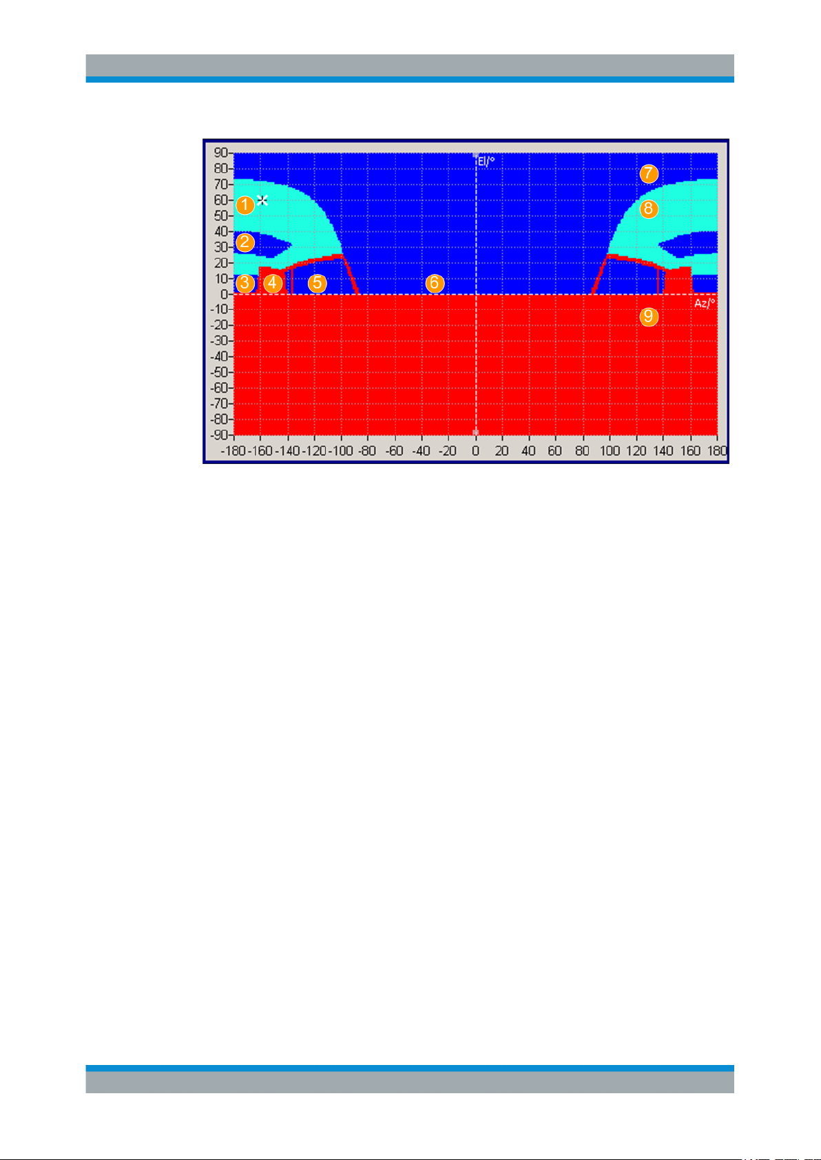
Real-World EnvironmentSatellite Navigation
Antenna Pattern and Body Mask
Figure 10-3: Body mask of the medium-sized car with roof-tops (Azimuth -180° to +180°)
1 = Roof
2 = Roof window
3 = Back window
4 = Seat
5 = Side window
6 = Front window
7 = Pass region (dark blue color): the incident signal is not attenuated and the table elements are set to 0 dB
8 = Attenuated pass region (light blue color): the incident signal is attenuated but not fully blocked; the table
elements are set to 15 dB.
9 = Non-pass region (red color): the incident signal is heavily blocked and the table elements are set to 40
dB
Possible application fields
●
Automotive applications
Attitude parameters are automatically extracted from the user-defined motion vector.
●
Body mask applications
Three files describe an antenna: the antenna pattern *.ant_pat (or power
response) file, the phase response *.phase file and the body mask file
*.body_mask.
Antenna pattern and phase response files must have the same filename and must
be stored in the same directory.
If the required *.phase file does not exist, the carrier phase matrix is assumed to
be zero.
●
Outdoor scenarios
Antenna pattern are applied on reflections from the defined environment model, e.g
multi-path.
●
Indoor absorption scenarios
84User Manual 1178.6379.02 ─ 01
Page 85

Real-World EnvironmentSatellite Navigation
How to Simulate Real-Word Effects
Antenna patterns can also be used to simulate the signal absorption and the carrier
phase bias from any angle around a GNSS receiver.
●
Over-the-air (OTA) test
You can also load antenna patterns measured by some over-the-air (OTA) measurements, e.g the R&S®DST200 RF Diagnostic Chamber.
10.4 Supported Multipath Models
Multipath is a term describing the situation when the satellite’s signal reaches the
receiver via two or more paths. The direct signal path is referred as the ling-of-sigh
(LOS) signal, whereas the reflected paths are called echoes. Multipath propagation
affects the accuracy of the pseudorange measurements.
The severity of the multipath propagation effect depends mainly on the following:
●
The signal strength of the echoes
●
The delay between the LOS component and the echoes
In R&S SMW you can define static multipath effects per satellite, see Chapter 10.8,
"Static Multipath", on page 92. The multipath model describing the static multipath
propagation is implemented as a tapped delay model and enables you to configure a
LOS component and up to 10 echoes per SV ID.
10.5 How to Simulate Real-Word Effects
● Visualizing the Effect of an Antenna Pattern...........................................................85
10.5.1 Visualizing the Effect of an Antenna Pattern
1. Select "GNSS > General > Set To Default".
2. Select "General > Simulation Mode > Navigation".
3. In the "Simulation Configuration > Systems&Signals" dialog, enable the required
navigation systems, e.g. a hybrid GPS, Galileo and GLONASS configuration.
4. Select "Simulation Configuration > Receiver > Position > Moving".
5. Select "Position Configuration > Waypont Files > Munich_Flight"
6. Select "Attitude Behaviour > Spinning".
7. Select "More > Spinning Rate = 0.1 Hz"
8. Select "Receiver > Antenna Configuration".
9. Select "A1 > Body Mask" and select one of the predefined files, e.g.
Space_Vehicle_3_antennas.ant_pat.
85User Manual 1178.6379.02 ─ 01
Page 86

Real-World EnvironmentSatellite Navigation
How to Simulate Real-Word Effects
10. Select "Display > Position" with "3D View > On" to observe the 3D positioning of
the three antennas.
11. Select "GNSS > General > State > On" to enable signal generation.
12. Select "Signal Monitor > Satellites > Sky View".
The display is updated in real time. You can observe how depending on the current
GNSS receiver position, the spinning rate and the current active antenna the
received GNSS signal changes.
13. Select "Satellites > Power View".
86User Manual 1178.6379.02 ─ 01
Page 87

Real-World EnvironmentSatellite Navigation
Antenna Configuration Settings
The power levels of the space vehicles are updated in real time, too.
14. Select "Receiver > Vehicle Dynamics".
The attitude indicator confirms the enabled spinning.
10.6 Antenna Configuration Settings
Option: R&S SMW-K108
Access:
1. Select "GNSS > Simulation Configuration > Receiver".
2. Set, for example, "Number of Antennas = 2".
87User Manual 1178.6379.02 ─ 01
Page 88

Real-World EnvironmentSatellite Navigation
Antenna Configuration Settings
3. Select "Antenna Configuration".
4. Select "Display > Body Mask".
The default configuration uses favorable conditions: isotropic antennas in open sky
environment.
5. For tests in more challenging environment, perform the following for each antenna:
a) Select "A# > Body Mask > Open Sky > Select Antenna Pattern File > Prede-
fined/User Files" and select the body mask description file.
b) Select "A# > Antenna Pattern > Isotropic > Select Antenna Pattern File > Pre-
defined/User Files" and select the antenna pattern file.
c) Confirm with "Select".
The "Select Antenna Pattern File" displays both, a list of available files and the con-
tent of the selected file.
6. To define which antenna is simulated, for example A1:
a) Select "A1" > Active.
b) Option: R&S SMW-K120
In "System Config > Mode > GNSS Advanced", select "Stream# > A1".
Note: Switching between the active antenna restarts the simulation.
The display is color coded, where the different power levels are indicated with different colors (see "Legend").
Three files describe an antenna, the body mask *.body_mask file, the antenna
pattern *.ant_pat file and the phase response *.phase file. The latter two files
must have the same filename and must be stored in the same directory. The
*.ant_pat file describes the power response matrix of each antenna.
With a selected antenna pattern, the R&S SMW simulates the satellite power and
carrier phase depending on the antenna pattern and attitude parameters.
88User Manual 1178.6379.02 ─ 01
Page 89

Real-World EnvironmentSatellite Navigation
Antenna Configuration Settings
Try out also the following:
1. In the "Antenna Configuration" dialog, select "3D View > On".
2. Select "Display > Antenna Pattern (Power)/(Phase)" to visualize the power and
phase response.
3. Select "Display > Position" to visualize the antenna's orientation and location compared to the center of gravity (COG).
Automotive applications
Extract the attitude parameters from the waypoint file as follows:
1. Select "Receiver > Position > Moving".
2. Select "Position Configuration > Attitude Behaviour > From Waypoint File".
Settings
Simulation Configuration > Receiver > Number of Antennas........................................89
Display.......................................................................................................................... 89
3D View.........................................................................................................................90
A x.................................................................................................................................90
Active............................................................................................................................ 90
Body Mask, Antenna Pattern........................................................................................ 90
Delta X, Delta Y, Delta Z...............................................................................................91
Delta Heading, Delta Elevation, Delta Bank..................................................................91
Edit > Body Mask/Antenna Pattern File........................................................................ 91
└ View Type....................................................................................................... 91
└ Azimuth, Elevation, Power Loss, Phase Response, Resolution.....................92
└ Save as...........................................................................................................92
Simulation Configuration > Receiver > Number of Antennas
Defines the number of configurable antennas.
You can create a pool of up to four antenna and body masks and switch between
them. To define which antenna is simulated, set "A#" > Active.
Note: Switching between the active antenna restarts the simulation.
Remote command:
[:SOURce<hw>]:BB:GNSS:RECeiver[:V<st>]:ANTenna:COUNt on page 234
Display
Select the antenna characteristics that are currently visualized.
If more than one antenna is enabled (e.g. "Receiver > Number of Antennas = 2"), the
displayed information corresponds to the currently selected one ("A# > Active > On").
The graph is merely a visualization. To change the values, select "A# > Filename >
Select Antenna Pattern File > Predefined/User Files" > "Edit".
89User Manual 1178.6379.02 ─ 01
Page 90

Real-World EnvironmentSatellite Navigation
Antenna Configuration Settings
"Position"
"Body Mask"
"Antenna Pattern (Power), Antenna Pattern (Phase)"
Remote command:
[:SOURce<hw>]:BB:GNSS:RECeiver[:V<st>]:ANTenna:DISPlay on page 234
3D View
Displays an interactive 3D representation of the body mask or the power/phase distribution the antenna.
Remote command:
[:SOURce<hw>]:BB:GNSS:RECeiver[:V<st>]:ANTenna:V3D on page 234
A x
Subsequent antenna number. It also selects the antenna whose pattern or body mask
is visualized.
Two displays that visualize the antenna position relative to the center
of gravity (COG):
●
On the left, the top view - shows the x/y direction
●
On the right, the side view - shows the x/z direction
To change the antenna position, set the parameters "ΔX, ΔY, ΔZ".
Visual representation of the body mask retrieved from the selected
file ("Body Mask").
Visual representation of the ppower/phase distribution as retrieved
from the selected antenna pattern file ("Antenna Pattern").
Active
●
In "System Config > Mode > Standard", activates the antenna and thus defines
which antenna is simulated.
●
Option: R&S SMW-K120
In "System Config > Mode > GNSS Advanced", select "Stream# > A1" to define
which antenna is simulated by which stream.
Remote command:
[:SOURce<hw>]:BB:GNSS:RECeiver[:V<st>]:A<ch>:STATe on page 236
Body Mask, Antenna Pattern
Displays the selected body mask and antenna pattern files.
To change a file, select its filename.
You access the standard "Select Antenna Pattern File" dialog to select (or edit) the file,
describing the body mask or the antenna pattern (*.ant_pat and *.body_mask).
Several predefined antenna patterns are provided but you can load your own files
("User Files"), too.
The "Select Antenna Pattern File" displays both, a list of available files and the content
of the selected file.
Select "Edit" to open a graphical editor for changing the file content.
See:
●
Edit > Body Mask/Antenna Pattern File
●
Chapter A.3, "Antenna Pattern and Body Mask Files", on page 401.
90User Manual 1178.6379.02 ─ 01
Page 91

Real-World EnvironmentSatellite Navigation
Antenna Configuration Settings
Remote command:
[:SOURce<hw>]:BB:GNSS:APATtern:CATalog:PREDefined? on page 235
[:SOURce<hw>]:BB:GNSS:APATtern:CATalog:USER? on page 235
[:SOURce<hw>]:BB:GNSS:RECeiver[:V<st>]:A<ch>:APATtern:FILE
on page 235
[:SOURce<hw>]:BB:GNSS:BODY:CATalog:PREDefined on page 235
[:SOURce<hw>]:BB:GNSS:BODY:CATalog:USER on page 235
[:SOURce<hw>]:BB:GNSS:RECeiver[:V<st>]:A<ch>:BODY:FILE on page 235
Delta X, Delta Y, Delta Z
Sets an offset relative to the center of gravity (COG) to place the antenna.
Remote command:
[:SOURce<hw>]:BB:GNSS:RECeiver[:V<st>]:A<ch>:DX on page 236
[:SOURce<hw>]:BB:GNSS:RECeiver[:V<st>]:A<ch>:DY on page 236
[:SOURce<hw>]:BB:GNSS:RECeiver[:V<st>]:A<ch>:DZ on page 236
Delta Heading, Delta Elevation, Delta Bank
Displays the information on the antenna orientation and tilt.
Remote command:
[:SOURce<hw>]:BB:GNSS:RECeiver[:V<st>]:A<ch>:DHEading on page 236
[:SOURce<hw>]:BB:GNSS:RECeiver[:V<st>]:A<ch>:DELevation
on page 236
[:SOURce<hw>]:BB:GNSS:RECeiver[:V<st>]:A<ch>:DBANk on page 236
Edit > Body Mask/Antenna Pattern File
Access: "Antenna Configuration > A# > Body Mask > Open Sky > Select Antenna Pattern File > Predefined/User Files", select the body mask description file and select
"Edit".
In this dialog you can change the file content, e.g. power loss values, and zoom in into
display areas.
View Type ← Edit > Body Mask/Antenna Pattern File
Toggles between the phase and power representation.
Works like "Display > Antenna Pattern (Power)" and "Antenna Pattern (Phase)".
91User Manual 1178.6379.02 ─ 01
Page 92

Real-World EnvironmentSatellite Navigation
Static Multipath
Azimuth, Elevation, Power Loss, Phase Response, Resolution ← Edit > Body
Mask/Antenna Pattern File
Displays the corresponding values of the selected point on the power/phase graph.
To edit the values, select an area on the graph, left mouse click and select "Edit Selec-
tion".
Save as ← Edit > Body Mask/Antenna Pattern File
Accesses the standard "File Select" dialog to save the antenna pattern or body mask
as a file. The predefined files cannot be overwritten. If a predefined file has been
changed, save it with a new filename.
Remote command:
n.a.
10.7 Environment Model and Environment Configuration
Option: R&S SMW-K108
Access:
1. Select "GNSS > Simulation Configuration > Receiver".
2. Select the environmental model, for example "Environment Model > Static Multipath".
3. Select "Environment Configuration".
See:
● Chapter 10.8, "Static Multipath", on page 92
Environment Model
Selects the environment model.
Remote command:
[:SOURce<hw>]:BB:GNSS:RECeiver[:V<st>]:ENVironment[:MODel]
on page 240
Environment Configuration
Accesses the configuration settings of the selected Environment Model.
10.8 Static Multipath
Access:
1. Select "GNSS > Simulation Configuration > Receiver".
2. Select "Environment Model > Static Multipath".
92User Manual 1178.6379.02 ─ 01
Page 93

Real-World EnvironmentSatellite Navigation
Static Multipath
3. Select "Environment Configuration".
With the provided parameters, you can simulate signals undergoing multipath propagation.
You can configure the number of echoes and the individual time and Doppler
shifts, power and carrier phase of each of them. A graph displays the resulting
propagation.
In advanced mode with several antennas, the dialog comprises of several tabs.
There is one per antenna so that you can define individual multipath conditions for
each of the antennas.
Settings
Standard, SV-ID (source), Copy To, Standard, SV-ID (target)..................................... 93
Number of Echos.......................................................................................................... 94
Line of Sight (LOS)........................................................................................................94
LOS and Echoes Table.................................................................................................94
└ Unit..................................................................................................................94
└ Init. Code Phase............................................................................................. 94
└ Code Phase Drift.............................................................................................95
└ Power Offset................................................................................................... 95
└ Init. Carrier Phase...........................................................................................95
└ Doppler Shift /Hz.............................................................................................95
└ AoA Elevation, AoA Azimuth...........................................................................95
Standard, SV-ID (source), Copy To, Standard, SV-ID (target)
Defines the GNSS standard and the SV ID for that the multipath is configured.
To use the same configuration for another SV ID or all other SV IDs, define the SV ID
as "Standard, SV-ID" (target) and select "Copy To".
93User Manual 1178.6379.02 ─ 01
Page 94

Real-World EnvironmentSatellite Navigation
Static Multipath
Remote command:
[:SOURce<hw>]:BB:GNSS:RECeiver[:V<st>]:ENVironment:MPATh:SYSTem
on page 240
[:SOURce<hw>]:BB:GNSS:RECeiver[:V<st>]:ENVironment:MPATh:SVID
on page 241
[:SOURce<hw>]:BB:GNSS:RECeiver[:V<st>]:ENVironment:MPATh:COPY:
SYSTem on page 241
[:SOURce<hw>]:BB:GNSS:RECeiver[:V<st>]:ENVironment:MPATh:COPY:
SVID on page 242
[:SOURce<hw>]:BB:GNSS:RECeiver[:V<st>]:ENVironment:MPATh:COPY:
EXECute on page 242
Number of Echos
Sets the echoes number. The value determines the number of rows available for configuration.
Remote command:
[:SOURce<hw>]:BB:GNSS:SVID<ch>:GPS:MPATh[:V<us>:A<gr>]:ECHos:
COUNt on page 243
(etc. for the other GNSS systems)
Line of Sight (LOS)
Defines if a LOS component is present or not.
Remote command:
[:SOURce<hw>]:BB:GNSS:SVID<ch>:GPS:MPATh[:V<us>:A<gr>]:LOS:
ENABle on page 243
(etc. for the other GNSS systems)
LOS and Echoes Table
Configuration of the LOS signal and the echoes, one row per multipath tap, where:
●
LOS is present if "Line of Sight (LOS) > On"
●
Number of echoes is defined by the parameter "Number of Echos"
Unit ← LOS and Echoes Table
You can change the units of the parameters. The affected values are automatically
recalculated.
Note: The selected units are used only in the manual control (display).
In remote control, SCPI commands always use the default units.
Init. Code Phase ← LOS and Echoes Table
Sets an initial code phase (or delay) for the selected echo. To simulated echo delay
variation with the time, set the parameters Code Phase Drift and Doppler Shift /Hz.
The severity of the multipath effect depends on the delay of the echoes and their
power.
Remote command:
[:SOURce<hw>]:BB:GNSS:SVID<ch>:GPS:MPATh[:V<us>:A<gr>]:
ECHO<s2us0>:ICPHase on page 244
(etc. for the other GNSS systems)
94User Manual 1178.6379.02 ─ 01
Page 95

Real-World EnvironmentSatellite Navigation
Static Multipath
Code Phase Drift ← LOS and Echoes Table
Sets a code phase drift that influences the delay of the echoes.
"Code Phase Drift" and "Doppler Shift" are interdependent. Changing either of them
affects the value of the other.
Remote command:
[:SOURce<hw>]:BB:GNSS:SVID<ch>:GPS:MPATh[:V<us>:A<gr>]:
ECHO<s2us0>:CPDRift on page 245
(etc. for the other GNSS systems)
Power Offset ← LOS and Echoes Table
Sets the additional power offset for the echo.
Remote command:
[:SOURce<hw>]:BB:GNSS:SVID<ch>:GPS:MPATh[:V<us>:A<gr>]:
ECHO<s2us0>:POWer on page 246
(etc. for the other GNSS systems)
Init. Carrier Phase ← LOS and Echoes Table
Sets the carrier phase at the simulation start.
Remote command:
[:SOURce<hw>]:BB:GNSS:SVID<ch>:GPS:MPATh[:V<us>:A<gr>]:
ECHO<s2us0>:CPHase on page 246
(etc. for the other GNSS systems)
Doppler Shift /Hz ← LOS and Echoes Table
Enters the additional Doppler shift that influences the delay of the echoes.
"Code Phase Drift" and "Doppler Shift" are interdependent. Changing either of them
affects the value of the other.
Remote command:
[:SOURce<hw>]:BB:GNSS:SVID<ch>:GPS:MPATh[:V<us>:A<gr>]:
ECHO<s2us0>:DSHift on page 247
(etc. for the other GNSS systems)
AoA Elevation, AoA Azimuth ← LOS and Echoes Table
Sets the angle of arrival parameters elevation and azimuth.
These parameters are considered if non-isotropic antenna patterns are used.
Remote command:
[:SOURce<hw>]:BB:GNSS:SVID<ch>:GPS:MPATh[:V<us>:A<gr>]:
ECHO<s2us0>:AELEVation on page 248
[:SOURce<hw>]:BB:GNSS:SVID<ch>:GPS:MPATh[:V<us>:A<gr>]:
ECHO<s2us0>:AAZimuth on page 248
(etc. for the other GNSS systems)
95User Manual 1178.6379.02 ─ 01
Page 96

Tracking ModeSatellite Navigation
Signal Dynamics Settings
11 Tracking Mode
Per default, the R&S SMW generates a GNSS signal that is suitable for testing the
receiver capabilities to acquire and track the signal and to estimate its position based.
Some receiver tests, however, focus on testing if the receiver is capable to acquire and
decode the signal; navigation and thus position estimation is not necessary. For such
tests or for receivers' sensitivity tests in zero-Doppler conditions or under varying signal
dynamics conditions, the R&S SMW provides the tracking mode.
With the provided signal dynamic settings, you can enable a predefined or constant
velocity profile, or define a user-specific one.
11.1 Signal Dynamics Settings
Access:
1. Select "GNSS > Test Mode" > "Tracking".
2. Select "GNSS > Simulation Configuration > Satellites".
3. Select the GNSS system for that you want to configure satellites constellation, for
example GPS.
4. Select "SV# > SV Config".
5. In the "SV Configuration" dialog, select "Signal Dynamics".
96User Manual 1178.6379.02 ─ 01
Page 97

6. Select, for example, "Mode > High Order".
Tracking ModeSatellite Navigation
Signal Dynamics Settings
Figure 11-1: Spinal Dynamics: Understanding the displayed information (Mode > Higher Order
1 = Velocity at the start of the profile
2 = Period of time the velocity is held constant
3 = Period of time an acceleration is applied
4 = Maximum acceleration together with the acceleration period and, if set the initial velocity, defines
the maximum velocity (7a and 7b)
5 = Defines how fast the maximum acceleration is reached
6 = Profile's duration, calculated form the selected periods of constant speed and acceleration; the
profile is repeated every 240 s.
7a = Maximum velocity = "Initial Velocity" + "Constant Acceleration Period"."Maximum Acceleration" =
500 m/s
7b = "Initial Velocity" - "Constant Acceleration Period"."Maximum Acceleration"
and Velocity Profile = User Dynamics)
Signal dynamics settings are provided for testing the receiver sensitivity under
varying signal dynamics conditions. You can select a predefined or constant velocity profile, or define a user-specific one.
The displayed settings depend on the selected "Mode" and "Velocity Profile". Dedicated plots visualize the variations of the velocity, acceleration and the jerk over
time.
Settings
Mode............................................................................................................................. 98
Inital Pseudorange........................................................................................................ 98
Inital Carrier Phase....................................................................................................... 98
Velocity (Pseudorange Rate)........................................................................................ 98
High-order profile settings.............................................................................................98
97User Manual 1178.6379.02 ─ 01
Page 98

Tracking ModeSatellite Navigation
Signal Dynamics Settings
└ Start Time Offset.............................................................................................99
└ Velocity Profile................................................................................................ 99
└ Initial Velocity..................................................................................................99
└ Constant Velocity Period.................................................................................99
└ Constant Acceleration Period......................................................................... 99
└ Maximum Acceleration..................................................................................100
└ Maximum Jerk...............................................................................................100
└ Repetition Period.......................................................................................... 100
Mode
Selects the dynamics profile type.
"Constant"
"High Order"
Remote command:
[:SOURce<hw>]:BB:GNSS:SVID<ch>:GPS:SDYNamics:PROFile on page 354
(etc. for the other GNSS systems)
Generates a constant velocity profile with configurable velocity, see
Velocity (Pseudorange Rate).
This mode is suitable for testing the receiver characteristics under
more realistic conditions than with zero Doppler.
Enables profiles with higher-order dynamics.
There are two predefined profiles and you can define your own one,
see High-order profile settings.
Inital Pseudorange
Sets the pseudorange at the beginning of the simulation.
Remote command:
[:SOURce<hw>]:BB:GNSS:SVID<ch>:GPS:SDYNamics:PRANge on page 355
Inital Carrier Phase
Sets the carrier phase at the beginning of the simulation.
Remote command:
[:SOURce<hw>]:BB:GNSS:SVID<ch>:GPS:SDYNamics:CPHase on page 354
Velocity (Pseudorange Rate)
In "Mode = Constant", sets the velocity, i.e. the constant Doppler with that the pseudorange changes. The pseudorange at a give moment is calculated from the initial pseudorange value and the velocity.
Velocity different than zero results in variation of the Doppler shift.
The velocity is constant, hence the acceleration and the jerk are zero. Observe also
the indications on the plots.
Remote command:
[:SOURce<hw>]:BB:GNSS:SVID<ch>:GPS:SDYNamics:VELocity on page 355
(etc. for the other GNSS systems)
High-order profile settings
In "Mode = High Order", observe the plots indicating the variations of the velocity,
acceleration and the jerk over time, see Figure 11-1.
98User Manual 1178.6379.02 ─ 01
Page 99

Tracking ModeSatellite Navigation
Signal Dynamics Settings
For both predefined profiles ("Velocity Profile = Low Dynamics or High Dynamics") the
profile settings are read-only.
To change the settings, set "Velocity Profile = User Dynamics".
Start Time Offset ← High-order profile settings
Sets a time delay before the dynamics profile is applied.
Remote command:
[:SOURce<hw>]:BB:GNSS:SVID<ch>:GPS:SDYNamics:TOFFset on page 355
(etc. for the other GNSS systems)
Velocity Profile ← High-order profile settings
Selects between the predefined velocity profiles or a user-defined one.
"Low Dynamics, High Dynamics"
Generates a profile using the settings of one of the predefined velocity profiles.
"User Dynamics"
Generates a velocity profile with user-defined parameters.
Remote command:
[:SOURce<hw>]:BB:GNSS:SVID<ch>:GPS:SDYNamics:CONFig on page 356
(etc. for the other GNSS systems)
Initial Velocity ← High-order profile settings
Indicates the start velocity, used at the beginning of the profile. This value is used at
the simulation start time or after the defined "Start Time Offset" elapses, see Fig-
ure 11-1.
Remote command:
[:SOURce<hw>]:BB:GNSS:SVID<ch>:GPS:SDYNamics:IVELocity on page 356
(etc. for the other GNSS systems)
Constant Velocity Period ← High-order profile settings
Displays the time period during that velocity is kept constant and the acceleration is
assumed to be 0.
Remote command:
[:SOURce<hw>]:BB:GNSS:SVID<ch>:GPS:SDYNamics:CVPeriod on page 357
(etc. for the other GNSS systems)
Constant Acceleration Period ← High-order profile settings
Displays the time duration during that acceleration is applied and thus the velocity varies.
The acceleration is calculated from the "Maximum Jerk" and the "Maximum Acceleration".
Remote command:
[:SOURce<hw>]:BB:GNSS:SVID<ch>:GPS:SDYNamics:CAPeriod on page 357
(etc. for the other GNSS systems)
99User Manual 1178.6379.02 ─ 01
Page 100

Tracking ModeSatellite Navigation
Signal Dynamics Settings
Maximum Acceleration ← High-order profile settings
Indicates the maximum acceleration. This value together with the acceleration period
and, if set the initial velocity, defines the maximum velocity.
Remote command:
[:SOURce<hw>]:BB:GNSS:SVID<ch>:GPS:SDYNamics:ACCel:MAX on page 358
(etc. for the other GNSS systems)
Maximum Jerk ← High-order profile settings
Indicates the maximum jerk that defines how fast the maximum acceleration is
reached.
Remote command:
[:SOURce<hw>]:BB:GNSS:SVID<ch>:GPS:SDYNamics:JERK:MAX on page 358
(etc. for the other GNSS systems)
Repetition Period ← High-order profile settings
Indicates the profile duration. The value is calculated automatically.
Remote command:
[:SOURce<hw>]:BB:GNSS:SVID<ch>:GPS:SDYNamics:RPERiod? on page 359
(etc. for the other GNSS systems)
100User Manual 1178.6379.02 ─ 01
 Loading...