

Page 1
®
R&S
SMBV100B
Vector Signal Generator
Getting Started
(>G:a2)
1423104902
Version 05
Getting Started
Page 2

This document describes the R&S®SMBV100B, stock no. 1423.1003.02 and its
options.
© 2019 Rohde & Schwarz GmbH & Co. KG
Mühldorfstr. 15, 81671 München, Germany
Phone: +49 89 41 29 - 0
Fax: +49 89 41 29 12 164
Email: info@rohde-schwarz.com
Internet: www.rohde-schwarz.com
Subject to change – Data without tolerance limits is not binding.
R&S® is a registered trademark of Rohde & Schwarz GmbH & Co. KG.
Trade names are trademarks of the owners.
1423.1049.02 | Version 05 | R&S®SMBV100B
The following abbreviations are used throughout this manual: R&S®SMBV100B is abbreviated as
R&S SMBV100B, R&S®WinIQSIM2TM is abbreviated as R&S WinIQSIM2, R&S®VISA is abbreviated as
R&S VISA.
Page 3

R&S®SMBV100B
Contents
1 Preface....................................................................................7
1.1 Key Features......................................................................................... 7
2 Safety and Regulatory Information...................................... 9
2.1 Safety Instructions................................................................................9
2.2 Labels on R&S SMBV100B.................................................................12
2.3 Korea Certification Class A................................................................12
3 Documentation Overview....................................................13
3.1 Getting Started Manual.......................................................................13
Contents
3.2 User Manuals and Help...................................................................... 13
3.3 Service Manual....................................................................................14
3.4 Instrument Security Procedures....................................................... 14
3.5 Basic Safety Instructions................................................................... 14
3.6 Data Sheets and Brochures............................................................... 14
3.7 Release Notes and Open Source Acknowledgment (OSA).............15
3.8 Application Notes, Application Cards, White Papers, etc...............15
4 Preparing for Use.................................................................17
4.1 Lifting and Carrying............................................................................17
4.2 Unpacking and Checking................................................................... 17
4.3 Choosing the Operating Site............................................................. 18
4.4 Setting Up the R&S SMBV100B......................................................... 18
4.4.1 Placing the R&S SMBV100B on a Bench Top...................................... 18
4.4.2 Mounting the R&S SMBV100B in a Rack............................................. 19
4.5 Important Aspects for Test Setup......................................................20
4.6 Connecting to Power.......................................................................... 22
3Getting Started 1423.1049.02 ─ 05
Page 4

R&S®SMBV100B
4.7 Connecting to LAN............................................................................. 22
4.8 Connecting USB Devices................................................................... 23
4.9 Connecting to RF................................................................................ 24
4.10 Connecting to LO In/Out.................................................................... 24
4.11 Connecting to Ref In/Ref Out.............................................................25
4.12 Connecting to HS Dig I/Q................................................................... 26
4.13 Switching On or Off............................................................................ 27
Contents
5 Instrument Tour................................................................... 31
5.1 Front Panel Tour..................................................................................31
5.1.1 Touchscreen..........................................................................................32
5.1.2 Keys...................................................................................................... 33
5.1.2.1 Utility Keys............................................................................................ 33
5.1.2.2 On/Standby........................................................................................... 33
5.1.2.3 Function Keys....................................................................................... 34
5.1.2.4 Keypad..................................................................................................34
5.1.2.5 Editing Keys.......................................................................................... 35
5.1.2.6 Navigation Controls...............................................................................35
Rotary Knob.......................................................................................... 35
Navigation Keys.................................................................................... 36
Display Keys......................................................................................... 36
5.1.3 Connectors............................................................................................37
5.2 Rear Panel Tour...................................................................................38
5.2.1 Connectors............................................................................................39
6 Trying Out the Instrument...................................................43
6.1 Generating an Unmodulated Carrier................................................. 43
6.2 Generating a Digitally Modulated Signal.......................................... 46
6.3 Triggering the Instrument with an External Signal.......................... 48
4Getting Started 1423.1049.02 ─ 05
Page 5

R&S®SMBV100B
6.4 Enabling and Configuring a Marker Signal...................................... 54
6.5 Verifying the Generated Signal with the Graphics Display.............55
6.6 Saving and Recalling Settings...........................................................58
6.7 Generating an EUTRA/LTE Signal..................................................... 61
Contents
7 System Overview................................................................. 67
7.1 Brief Introduction to the Instrument's Concept............................... 67
7.2 Signal Flow at a Glance......................................................................67
7.3 Internal Baseband Source ("Baseband" Block)...............................69
7.4 Digital Baseband Input ("BB Input"Block)....................................... 69
7.5 Additional White Gaussian Noise ("AWGN" Block).........................70
7.6 "I/Q Stream Mapper" Block................................................................ 70
7.7 I/Q Modulator ("I/Q Mod" Block)........................................................ 70
7.8 Analog I/Q Output ("I/Q Analog" Block)............................................71
7.9 RF and Analog Modulations ("RF" Block)........................................ 71
7.10 Applications Examples of the R&S SMBV100B............................... 71
8 Instrument Control.............................................................. 73
8.1 Possible Ways to Operate the Instrument........................................73
8.2 Means of Manual Interaction..............................................................74
8.3 Understanding the Display Information............................................75
8.3.1 Status Bar............................................................................................. 75
8.3.2 Block Diagram.......................................................................................76
8.3.3 Taskbar................................................................................................. 77
8.3.4 Additional Display Characteristics.........................................................78
8.4 Accessing the Functionality.............................................................. 80
8.5 Entering Data.......................................................................................82
8.5.1 Entering Numeric Parameters...............................................................82
8.5.2 Entering Alphanumeric Parameters...................................................... 83
5Getting Started 1423.1049.02 ─ 05
Page 6

R&S®SMBV100B
8.5.3 Undo and Redo Actions........................................................................ 83
8.6 Getting Information and Help............................................................ 83
8.7 Remote Control................................................................................... 85
8.8 Remote Operation over VNC..............................................................86
Contents
9 Contacting Customer Support........................................... 87
Index..................................................................................... 89
6Getting Started 1423.1049.02 ─ 05
Page 7

R&S®SMBV100B
Key Features
Preface
1 Preface
The R&S SMBV100B is a new signal generator developed to meet demanding
customer requirements. Offering excellent signal characteristic and straightforward and intuitive operation, the signal generator makes signal generation fast
and easy.
1.1 Key Features
The R&S SMBV100B is a new high-performance signal generator developed to
meet demanding customer requirements. Offering excellent signal characteristic
and straightforward and intuitive operation, the signal generator makes signal
generation fast and easy.
Outstanding key features of the R&S SMBV100B are:
●
Frequency range from 8 kHz to 6 GHz
●
Up to 500 MHz I/Q modulation bandwidth (in RF) with internal baseband
●
Support of all important digital standards such as LTE incl eMTC/NB-IoT, 5G
NR, WLAN IEEE 802.11a/b/g/n/j/p/ac/ax, 3GPP FDD/HSPA/HSPA+
●
Excellent signal quality for high accuracy in spectral and modulation measurements
●
Intuitive operation via touchscreen with block diagram as key element
●
Graphical signal monitoring at practically every point in the signal flow
●
SCPI macro recorder and code generator for generating executable remote
control code from manual operating steps (for MATLAB®, CVI, etc.)
For more information, see data sheet.
7Getting Started 1423.1049.02 ─ 05
Page 8

R&S®SMBV100B
Preface
Key Features
8Getting Started 1423.1049.02 ─ 05
Page 9

R&S®SMBV100B
Safety and Regulatory Information
Safety Instructions
2 Safety and Regulatory Information
The product documentation helps you use the R&S SMBV100B safely and efficiently. Follow the instructions provided here and in the Chapter 2.1, "Safety
Instructions", on page 9.
Intended use
The R&S SMBV100B is intended for the development, production and verification
of electronic components and devices in industrial, administrative, and laboratory
environments. Use the R&S SMBV100B only for its designated purpose. Observe
the operating conditions and performance limits stated in the data sheet.
Where do I find safety information?
Safety information is part of the product documentation. It warns you of potential
dangers and gives instructions on how to prevent personal injury or damage
caused by dangerous situations. Safety information is provided as follows:
●
In Chapter 2.1, "Safety Instructions", on page 9. The same information is
provided in many languages as printed "Safety Instructions". The printed
"Safety Instructions" are delivered with the R&S SMBV100B.
●
Throughout the documentation, safety instructions are provided when you
need to take care during setup or operation.
2.1 Safety Instructions
Products from the Rohde & Schwarz group of companies are manufactured
according to the highest technical standards. To use the products safely, follow
the instructions provided here and in the product documentation. Keep the product documentation nearby and offer it to other users.
Use the product only for its intended use and within its performance limits. Intended use and limits are described in the product documentation such as the data
sheet, manuals and the printed safety instructions. If you are unsure about the
appropriate use, contact Rohde & Schwarz customer service.
Using the product requires specialists or specially trained personnel. These users
also need sound knowledge of at least one of the languages in which the user
interfaces and the product documentation are available.
9Getting Started 1423.1049.02 ─ 05
Page 10

R&S®SMBV100B
If any part of the product is damaged or broken, stop using the product. Never
open the casing of the product. Only service personnel authorized by
Rohde & Schwarz are allowed to repair the product. Contact Rohde & Schwarz
customer service at http://www.customersupport.rohde-schwarz.com.
Lifting and carrying the product
Some products are heavy. A safety label on the casing indicates if a product
weighs more than 18 kg. To safely move the product, you can use lifting or transporting equipment such as lift trucks, cranes, forklifts and hand trucks. Secure the
product, but not by its handles. Excessive force can break the handles.
Choosing the operating site
Only use the product indoors. The product casing is not waterproof and water that
enters can electrically connect the casing with live parts. This can lead to electric
shock, serious personal injury or death if you touch the casing.
Safety and Regulatory Information
Safety Instructions
Unless otherwise specified, you can operate the product up to an altitude of
2000 m above sea level. The product is suitable for pollution degree 2 environments where nonconductive contamination can occur. For more information on
environmental conditions such as ambient temperature and humidity, see the
data sheet.
Setting up the instrument
Always place the instrument on a stable, flat and level surface with the bottom of
the instrument facing down.
To save space, you can mount several instruments in a rack. If you stack instruments, keep in mind that a stack of instruments can tilt over and cause injury.
If the instrument has foldable feet, always fold the feet completely in or out to
ensure stability. The feet can collapse if they are not folded out completely or if
the instrument is moved without lifting it. The foldable feet are designed to carry
the weight of the instrument, but not an extra load.
Connecting to power
The product is an overvoltage category II product and has to be connected to a
fixed installation used to supply energy-consuming equipment such as household
appliances and similar loads. Be aware that electrically powered products have
risks, such as electric shock, fire, personal injury or even death.
10Getting Started 1423.1049.02 ─ 05
Page 11

R&S®SMBV100B
Take the following measures for your safety:
●
Before switching on the product, ensure that the voltage and frequency indicated on the product match the available power source. If the power adapter
does not adjust automatically, set the correct value and check the rating of the
fuse.
●
If a product has an exchangeable fuse, its type and characteristics are indicated next to the fuse holder. Before changing the fuse, switch off the instrument
and disconnect it from the power source. How to change the fuse is described
in the product documentation.
●
Only use the power cable delivered with the product. It complies with countryspecific safety requirements. Only insert the plug into an approved grounded
outlet.
●
Only use intact cables and route them carefully so that they cannot be damaged. Check the power cables regularly to ensure that they are undamaged.
Also ensure that nobody can trip over loose cables.
Safety and Regulatory Information
Safety Instructions
●
If the product needs an external power supply, use the power supply that is
delivered with the product or that is recommended in the product documentation or a power supply that conforms to the country-specific regulations.
●
Only connect the product to a power source with a fuse protection of maximum 20 A.
●
Ensure that you can disconnect the product from the power source at any
time. Pull the power plug to disconnect the product. The power plug must be
easily accessible. If the product is integrated into a system that does not meet
these requirements, provide an easily accessible circuit breaker at the system
level.
Cleaning the product
Use a dry, lint-free cloth to clean the product. When cleaning, keep in mind that
the casing is not waterproof. Do not use liquid cleaning agents.
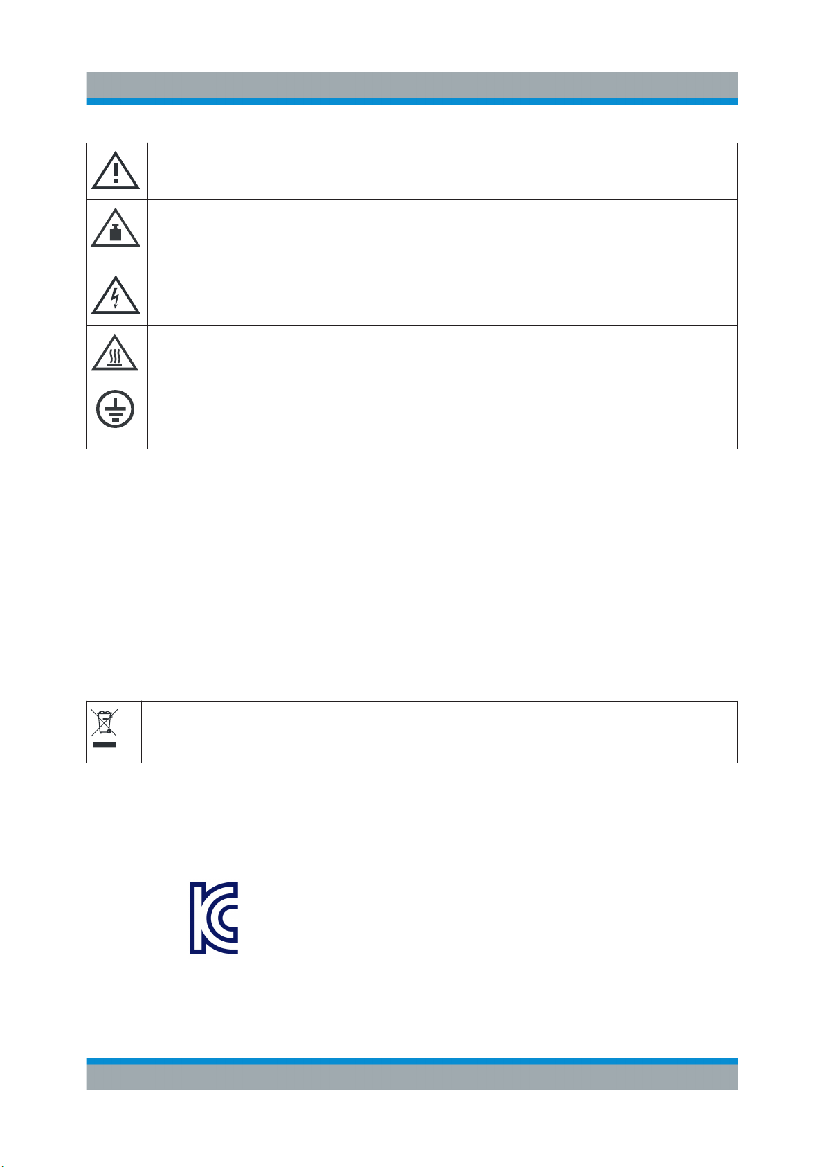
Meaning of safety labels
Safety labels on the product warn against potential hazards.
11Getting Started 1423.1049.02 ─ 05
Page 12
R&S®SMBV100B
Potential hazard
Read the product documentation to avoid personal injury or product damage.
Heavy product
Be careful when lifting, moving or carrying the product. Carrying the product requires
at least two people or transport equipment.
Electrical hazard
Indicates live parts. Risk of electric shock, fire, personal injury or even death.
Hot surface
Do not touch. Risk of skin burns. Risk of fire.
Protective conductor terminal
Connect this terminal to a grounded external conductor or to protective ground. This
protects you against electric shock should an electric problem occur.
Safety and Regulatory Information
Korea Certification Class A
2.2 Labels on R&S SMBV100B
Labels on the casing inform about:
●
Personal safety, see "Connecting to power" on page 10.
●
Product and environment safety, see Table 2-1.
●
Identification of the product, see the serial number on the rear panel.
Table 2-1: Labels regarding R&S SMBV100B and environment safety
Labeling in line with EN 50419 for disposal of electrical and electronic equipment after
the product has come to the end of its service life. For more information, see the product user manual, chapter "Disposal".
2.3 Korea Certification Class A
이 기기는 업무용(A급) 전자파 적합기기로서 판매자 또는 사용자는 이 점을 주의하
시기 바라며, 가정외의 지역에서 사용하는 것을 목적으로 합니다.
12Getting Started 1423.1049.02 ─ 05
Page 13

R&S®SMBV100B
Documentation Overview
User Manuals and Help
3 Documentation Overview
This section provides an overview of the R&S SMBV100B user documentation.
Unless specified otherwise, you find the documents on the R&S SMBV100B product page at:
www.rohde-schwarz.com/manual/smbv100b
3.1 Getting Started Manual
Introduces the R&S SMBV100B and describes how to set up and start working
with the product. Includes basic operations, typical measurement examples, and
general information, e.g. safety instructions, etc. A printed version is delivered
with the instrument.
3.2 User Manuals and Help
Separate manuals for the base unit and the software options are provided for
download:
●
Base unit manual
Contains the description of all instrument modes and functions. It also provides an introduction to remote control, a complete description of the remote
control commands with programming examples, and information on maintenance, instrument interfaces and error messages. Includes the contents of the
getting started manual.
●
Software option manual
Contains the description of the specific functions of an option. Basic information on operating the R&S SMBV100B is not included.
All user manuals are also available for download or for immediate display on the
Internet.
13Getting Started 1423.1049.02 ─ 05
Page 14

R&S®SMBV100B
Documentation Overview
Data Sheets and Brochures
3.3 Service Manual
Describes the performance test for checking the rated specifications, module
replacement and repair, firmware update, troubleshooting and fault elimination,
and contains mechanical drawings and spare part lists.
The service manual is available for registered users on the global
Rohde & Schwarz information system (GLORIS, https://gloris.rohde-
schwarz.com).
3.4 Instrument Security Procedures
Deals with security issues when working with the R&S SMBV100B in secure
areas. It is available for download on the Internet.
3.5 Basic Safety Instructions
Contains safety instructions, operating conditions and further important information. The printed document is delivered with the instrument.
3.6 Data Sheets and Brochures
The data sheet contains the technical specifications of the R&S SMBV100B. It
also lists the options and their order numbers and optional accessories.
The brochure provides an overview of the instrument and deals with the specific
characteristics.
See www.rohde-schwarz.com/brochure-datasheet/smbv100b
14Getting Started 1423.1049.02 ─ 05
Page 15

R&S®SMBV100B
Application Notes, Application Cards, White Papers, etc.
Documentation Overview
3.7 Release Notes and Open Source Acknowledgment (OSA)
The release notes list new features, improvements and known issues of the current firmware version, and describe the firmware installation.
The open source acknowledgment document provides verbatim license texts of
the used open source software.
See www.rohde-schwarz.com/firmware/smbv100b
3.8 Application Notes, Application Cards, White Papers, etc.
These documents deal with special applications or background information on
particular topics.
See www.rohde-schwarz.com/application/smbv100b
15Getting Started 1423.1049.02 ─ 05
Page 16

R&S®SMBV100B
Documentation Overview
Application Notes, Application Cards, White Papers, etc.
16Getting Started 1423.1049.02 ─ 05
Page 17

R&S®SMBV100B
Unpacking and Checking
Preparing for Use
4 Preparing for Use
This chapter describes the basic steps to be taken when setting up the
R&S SMBV100B for the first time.
4.1 Lifting and Carrying
See also "Lifting and carrying the product" on page 10.
► Use the carrying handle at the side for lifting and carrying the
R&S SMBV100B.
For mounting the R&S SMBV100B in a rack, see Chapter 4.4.2, "Mounting the
R&S SMBV100B in a Rack", on page 19.
4.2 Unpacking and Checking
1. Unpack the R&S SMBV100B carefully.
2. Retain the original packing material. Use it to protect the control elements and
connectors when transporting or shipping the R&S SMBV100B later.
See also chapter "Transporting" in the user manual.
3. Using the delivery notes, check the equipment for completeness.
4. Check the equipment for damage.
If the delivery is incomplete or equipment is damaged, contact
Rohde & Schwarz.
17Getting Started 1423.1049.02 ─ 05
Page 18

R&S®SMBV100B
Setting Up the R&S SMBV100B
Preparing for Use
4.3 Choosing the Operating Site
Specific operating conditions ensure accurate measurements and avoid damage
to the R&S SMBV100B and connected devices. For information on environmental
conditions such as ambient temperature and humidity, see the data sheet.
See also "Choosing the operating site" on page 10.
Electromagnetic compatibility classes
The electromagnetic compatibility (EMC) class indicates where you can operate
the R&S SMBV100B. The EMC class of the R&S SMBV100B is given in the data
sheet under "General data".
●
Class B equipment is suitable for use in:
– Residential environments
– Environments that are directly connected to a low-voltage supply network
that supplies residential buildings
●
Class A equipment is intended for use in industrial environments. It can cause
radio disturbances in residential environments due to possible conducted and
radiated disturbances. It is therefore not suitable for class B environments.
If class A equipment causes radio disturbances, take appropriate measures to
eliminate them.
4.4 Setting Up the R&S SMBV100B
See also:
●
"Setting up the instrument" on page 10.
●
"Intended use" on page 9.
4.4.1 Placing the R&S SMBV100B on a Bench Top
To place the R&S SMBV100B on a bench top
1. Place the R&S SMBV100B on a stable, flat and level surface. Ensure that the
surface can support the weight of the R&S SMBV100B. For information on the
weight, see the data sheet.
18Getting Started 1423.1049.02 ─ 05
Page 19

R&S®SMBV100B
Preparing for Use
Setting Up the R&S SMBV100B
2. CAUTION! Foldable feet can collapse. See "Setting up the instrument"
on page 10.
Always fold the feet completely in or out. With folded-out feet, do not place
anything on top or underneath the instrument.
3. WARNING! A stack of instruments can fall over and cause injury. Never stack
more than three instruments on top of each other. Instead, mount them in a
rack.
Stack as follows:
● It is best if all instruments have the same dimensions (width and length).
● The overall load on the lowest instrument must not exceed 500 N.
● With smaller instruments on top of the lowest instrument, the overall load
on the lowest instrument must not exceed 250 N.
max. 500 N
Correct Different dimensions
max. 250 N
Too many instruments
4. NOTICE! Overheating can damage the R&S SMBV100B.
Prevent overheating as follows:
● Keep a minimum distance of 10 cm between the fan openings of the
R&S SMBV100B and any object in the vicinity.
● Do not place the R&S SMBV100B next to heat-generating equipment such
as radiators or other instruments.
4.4.2 Mounting the R&S SMBV100B in a Rack
To prepare the rack
1. Observe the requirements and instructions in "Setting up the instrument"
on page 10.
2. NOTICE! Insufficient airflow can cause overheating and damage the
R&S SMBV100B.
19Getting Started 1423.1049.02 ─ 05
Page 20

R&S®SMBV100B
Important Aspects for Test Setup
Design and implement an efficient ventilation concept for the rack.
To mount the R&S SMBV100B in a rack
1. Use an adapter kit that fits the dimensions of the R&S SMBV100B to prepare
the instrument for rack mounting. For information on the dimensions, see data
sheet.
a) Order the rack adapter kit designed for the R&S SMBV100B. For the order
number, see data sheet.
b) Mount the adapter kit. Follow the assembly instructions provided with the
adapter kit.
2. Lift the R&S SMBV100B to shelf height.
3. Grab the handles and push the R&S SMBV100B onto the shelf until the rack
brackets fit closely to the rack.
Preparing for Use
4. Tighten all screws at the rack brackets with a tightening torque of 1.2 Nm to
secure the R&S SMBV100B at the rack.
To unmount the R&S SMBV100B from a rack
1. Loosen the screws at the rack brackets.
2. Bring the lifting equipment to shelf height.
3. Remove the R&S SMBV100B from the rack.
4. If placing the R&S SMBV100B on a bench top again, unmount the adapter kit
from the R&S SMBV100B. Follow the instructions provided with the adapter
kit.
4.5 Important Aspects for Test Setup
Cable selection and electromagnetic interference (EMI)
Electromagnetic interference (EMI) can affect the measurement results.
To suppress electromagnetic radiation during operation:
●
Use high-quality shielded cables, especially for the following connector types:
– BNC
Double-shielded BNC cables.
20Getting Started 1423.1049.02 ─ 05
Page 21

R&S®SMBV100B
Important Aspects for Test Setup
– USB
Double-shielded USB cables.
How to: Chapter 4.8, "Connecting USB Devices", on page 23.
See also chapter "Troubleshooting and Error Messages" in the user manual.
– LAN
At least CAT6 STP cables.
How to: Chapter 4.7, "Connecting to LAN", on page 22
●
Always terminate open cable ends.
●
Ensure that connected external devices comply with EMC regulations.
●
Use cables of the same type and equal length for connection to the I/Q and
I/Q Bar interfaces of the instrument.
●
Use the cable R&S SMU-Z6 for connection to the Dig I/Q interfaces of the
instrument. The cable is available under material number 1415.0201.02.
Preparing for Use
●
Use the cable R&S DIGIQ-HS for connection to the HS Dig I/Q interfaces of
the instrument. The cable is available under material number 3641.2948.03.
How to: Chapter 4.12, "Connecting to HS Dig I/Q", on page 26
Signal input and output levels
Information on signal levels is provided in the data sheet. Keep the signal levels
within the specified ranges to avoid damage to the R&S SMBV100B and connected devices.
Preventing electrostatic discharge (ESD)
Electrostatic discharge is most likely to occur when you connect or disconnect a
DUT.
► NOTICE! Risk of electrostatic discharge. Electrostatic discharge can damage
the electronic components of the R&S SMBV100B and the device under test
(DUT).
Ground yourself to prevent electrostatic discharge damage:
a) Use a wrist strap and cord to connect yourself to ground.
b) Use a conductive floor mat and heel strap combination.
21Getting Started 1423.1049.02 ─ 05
Page 22

R&S®SMBV100B
Preparing for Use
Connecting to LAN
4.6 Connecting to Power
For safety information, see "Connecting to power" on page 10.
1. Plug the AC power cable into the AC power connector on the rear panel of the
instrument. Only use the AC power cable delivered with the R&S SMBV100B.
2. Plug the AC power cable into a power outlet with ground contact.
The required ratings are listed next to the AC power connector and in the data
sheet.
4.7 Connecting to LAN
You can operate the R&S SMBV100B via LAN (local area network) or you can
operate it locally. This section describes how to connect the instrument to a LAN
to operate or control the instrument remotely via a PC in a LAN.
The connector is located on the rear panel.
► Connect the LAN socket via an RJ-45 cable to the LAN.
By default, the R&S SMBV100B is configured to use DHCP (dynamic host configuration protocol) and no static IP address is configured.
If switched on and connected to the LAN, the R&S SMBV100B displays the
address information on the screen.
Figure 4-1: IP address indication on the screen (example)
See also the chapter "Connecting the Instrument to the Network (LAN)" in the
user manual.
22Getting Started 1423.1049.02 ─ 05
Page 23

R&S®SMBV100B
Connecting USB Devices
Preparing for Use
4.8 Connecting USB Devices
USB connectors are located on the front panel and rear panel. You can connect
or disconnect all USB devices from the R&S SMBV100B during operation.
To connect USB storage devices
USB storage devices, such as memory sticks, allow easy data transfer from/to the
R&S SMBV100B. You can also use them for firmware updates.
► Connect the USB storage device to the USB type A connector.
If you use the front panel connectors, connect the USB storage device directly,
without connecting cable. Connecting cables can cause electromagnetic radiation and impair the measurement result.
To connect USB devices with external power supply
1. NOTICE! Connected devices with external power supply can feed back current into the 5 V power supply of the USB interface and thus damage the
R&S SMBV100B.
Ensure that there is no connection between the positive pole of the power
supply and the +5 V power pin of the USB interface (VBUS).
2. Connect the USB storage device to the USB connector on the rear panel.
To connect a keyboard
► Connect the keyboard to the USB connector on the rear panel.
When connected, the R&S SMBV100B detects the keyboard automatically. A
detected keyboard has the default layout English – US.
To connect a mouse
► Connect the mouse to the USB connector on the rear panel.
When connected, the R&S SMBV100B detects the mouse automatically.
To connect power sensors
Connect power sensors of the R&S NRP families to the USB connector on the
rear panel.
23Getting Started 1423.1049.02 ─ 05
Page 24

R&S®SMBV100B
Connecting to LO In/Out
See chapter "Using Power Sensors" in the user manual.
Preparing for Use
4.9 Connecting to RF
The connector is located on the front panel.
If you have the instrument equipped with an option for rear panel connectors, the
RF output connector is located on the rear panel.
To prepare for connecting to "RF"
1. If the R&S SMBV100B is switched on, deactivate the RF output, before connecting an RF cable to the RF connector.
In the block diagram, select the block "RF" > "RF Level" > "RF ON > Off".
2. Use a high-quality RF cable that matches the RF connector type.
See "Cable selection and electromagnetic interference (EMI)" on page 20.
To connect to non-screwable connectors (BNC)
► To connect the RF cable with the "RF" connector, proceed as follows:
a) Carefully align the connector of the cable and the "RF" connector along a
common axis.
b) Mate the connectors along the common axis until the male pin of the con-
nector of the cable engages with the female socket of the "RF" connector.
Preventing RF output switch-off
► NOTICE! If you set a too high output level, the reverse power can exceed a
limit forcing the R&S SMBV100B to switch off the RF output.
Set an RF output level that is not higher than the maximum permissible RF
power as given in the data sheet.
4.10 Connecting to LO In/Out
"LO In/Out" connectors are Subminiature Version A (SMA) connectors.
The connector is located on the rear panel.
24Getting Started 1423.1049.02 ─ 05
Page 25

R&S®SMBV100B
Preparing for Use
Connecting to Ref In/Ref Out
1. Use a high-quality cable that matches the connector type.
See "Cable selection and electromagnetic interference (EMI)" on page 20.
2. NOTICE! Risk of instrument damage and connector damage. Excessive tightening can damage the cables and the connectors. However, if you do not
tighten the connectors enough, the measurement results can be inaccurate.
To connect the cable with the connector, proceed as follows:
a) Carefully align the connector of the cable and the connector along a com-
mon axis.
b) Mate the connectors along the common axis until the male pin of the inner
connector engages with the female socket of the outer connector.
c) Turn the nut of the outer connector until the connectors are firmly coupled.
d) Torque the nut to the specified limit using a calibrated torque wrench. Hold
the opposite connector part stationary with a spanner.
For torque limits of the most relevant connector types, see Table 4-1.
3. Torque the nut to the specified limit using a calibrated torque wrench. Hold the
opposite connector part stationary with a spanner.
For more information, see chapter "Handling" of the application note 1MA99.
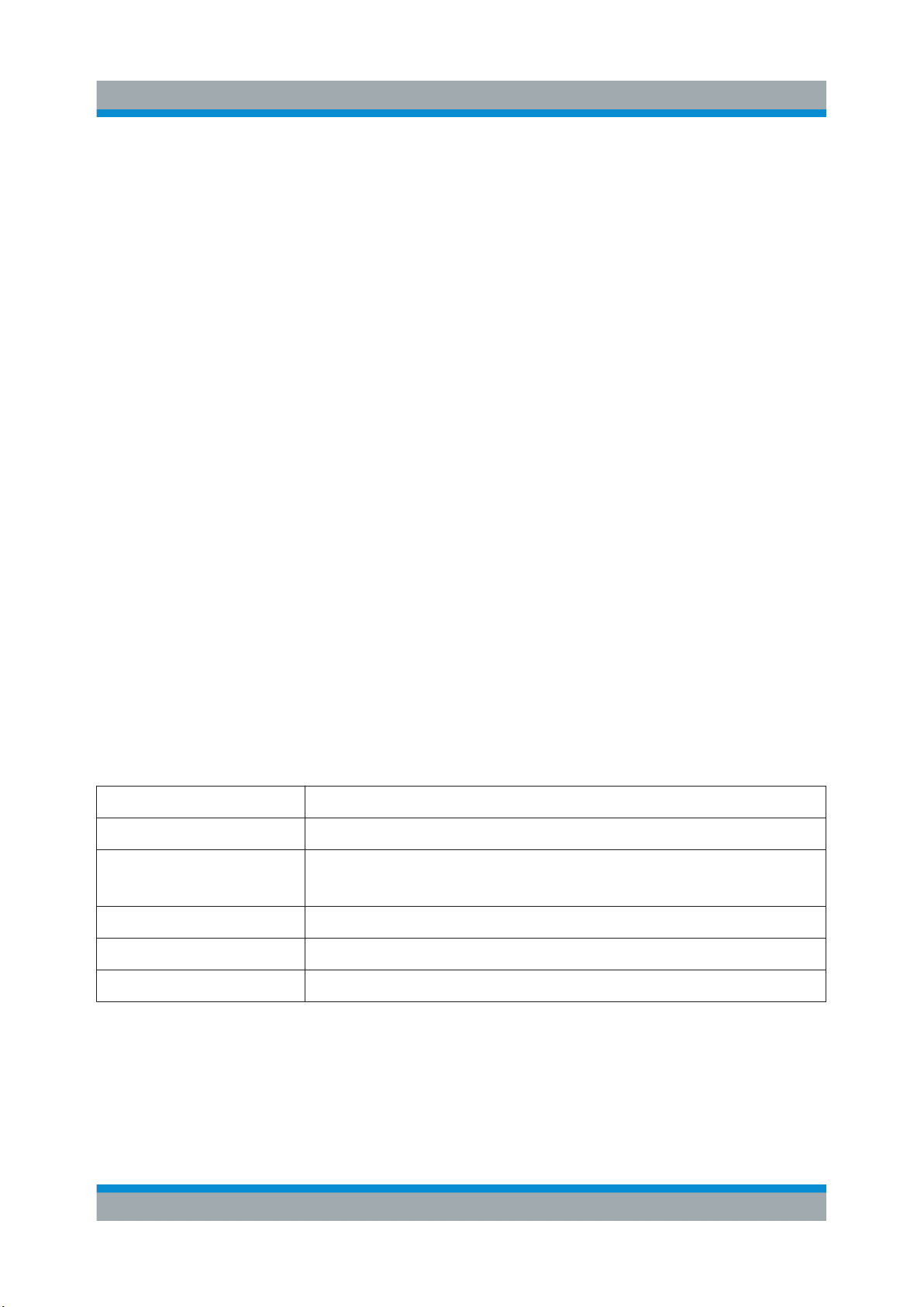
Table 4-1: Connector types and torque limits
Type Torque limit Nut opening
N 13.3 1.5 3/4 20
SMA 5 0.56 5/16 8
3.5 mm 8 0.9 5/16 8
2.92 mm 8 0.9 5/16 8
2.4 mm 8 0.9 5/16 8
1.85 mm 8 0.9 5/16 8
1.0 mm 3 0.34 0.236 6
lb-Inch Nm Inch mm
See also chapter "Local Oscillator Coupling" in the user manual.
4.11 Connecting to Ref In/Ref Out
The connector is located on the rear panel.
25Getting Started 1423.1049.02 ─ 05
Page 26

R&S®SMBV100B
Connecting to HS Dig I/Q
To connect to "Ref In"/"Ref Out" (reference < 1 GHz)
For connection, the R&S SMBV100B provides BNC connectors.
► Follow the instructions in "To connect to non-screwable connectors (BNC)"
on page 24.
To connect to "Ref In"/"Ref Out" (reference = 1 GHz)
For connection, the R&S SMBV100B provides SMA connectors.
► Follow the instructions in Chapter 4.10, "Connecting to LO In/Out",
on page 24.
To connect to Ref In/Ref Out (reference = 1 GHz)
For connection, the R&S SMBV100B provides SMA connectors.
Preparing for Use
► Follow the instructions in Chapter 4.10, "Connecting to LO In/Out",
on page 24.
4.12 Connecting to HS Dig I/Q
The HS Dig I/Q connector comprises a QSFP+ (Quad Small Form-factor Pluggable) socket, that has two components: a QSFP+ connector and a QSFP+ cage.
The QSFP+ cable is equipped with the QSFP+ plug.
26Getting Started 1423.1049.02 ─ 05
Page 27

R&S®SMBV100B
Preparing for Use
Switching On or Off
1 = QSFP+ plug
2 = QSFP+ cage
3 = QSFP+ connector
The connector is located on the rear panel.
To connect to HS Dig I/Q interface
1. For connection, use the QSFP+ cable R&S DIGIQ-HS.
See "Cable selection and electromagnetic interference (EMI)" on page 20.
2. Hold the QSFP+ plug of the cable by its panes.
3. Turn the QSFP+ cable, so that the release tab shows upwards.
4. Insert and push the QSFP+ plug into the QSFP+ cage.
To disconnect from HS Dig I/Q interface
1. NOTICE! If you pull the cable, you can damage the cable and the HS Dig I/Q
connector.
Pull the release tab.
2. Pull the QSFP+ plug out of the QSFP+ cage.
See also "Digital Baseband Input Settings" in the user manual.
4.13 Switching On or Off
The following table provides an overview of power states, LEDs and power switch
positions.
Table 4-2: Overview of power states
State LED Position of power switch
Off
Standby
gray
orange
[0]
[I]
Ready
green
[I]
27Getting Started 1423.1049.02 ─ 05
Page 28

R&S®SMBV100B
To switch on the R&S SMBV100B
The R&S SMBV100B is off but connected to power. See Chapter 4.6, "Connect-
ing to Power", on page 22.
1. Set the switch on the power supply to position [I].
The switch is located on the rear panel.
The LED of the [On/Standby] key is orange.
2. Wait until the oven-controlled oscillator (OCXO) warms up. For the warm-up
time, see data sheet.
3. Press the [On/Standby] key.
Key and LED are located on the front panel.
The LED changes to green. The R&S SMBV100B boots.
When starting for the first time, the R&S SMBV100B starts with the default
settings. When restarting the instrument, the settings depend on the instrument configuration before shut-down.
See the chapter "Saving and Recalling Instrument Settings" in the user manual.
Preparing for Use
Switching On or Off
When the instrument is switched on, it automatically monitors main functions. You
can query erroneous functions. In addition to automatic monitoring, you can perform maintenance tasks.
See:
●
Chapter "Querying Error Messages" in the user manual.
●
Chapter "Performing Maintenance Tasks" in the user manual.
To shut down the R&S SMBV100B
The R&S SMBV100B is in the ready state.
► Press the On/Standby key.
The operating system shuts down. The LED changes to orange.
In the standby state, the power switch circuits and the OCXO are active. To deactivate them, disconnect the instrument from the power supply.
28Getting Started 1423.1049.02 ─ 05
Page 29

R&S®SMBV100B
To disconnect from power
The R&S SMBV100B is in the standby state.
1. NOTICE! Risk of data loss. If you disconnect the R&S SMBV100B from power
when it is in the ready state, you can lose settings and data. Shut it down first.
Set the toggle switch on the power supply to position [0].
The LED of the [On/Standby] key is switched off.
2. Disconnect the R&S SMBV100B from the power source.
Preparing for Use
Switching On or Off
29Getting Started 1423.1049.02 ─ 05
Page 30

R&S®SMBV100B
Preparing for Use
Switching On or Off
30Getting Started 1423.1049.02 ─ 05
Page 31

R&S®SMBV100B
Instrument Tour
Front Panel Tour
5 Instrument Tour
The following topics help you get familiar with the instrument and perform the first
steps:
●
Front Panel Tour
●
Rear Panel Tour
This section explains the control elements and the connectors of the
R&S SMBV100B with the aid of the front and rear views. For specifications of the
interfaces, refer to the data sheet.
The meanings of the labels on the R&S SMBV100B are described in Chapter 2.2,
"Labels on R&S SMBV100B", on page 12.
5.1 Front Panel Tour
This section provides an overview of the control elements and connectors on the
front panel of the R&S SMBV100B. On the rear panel, you find all further connectors of the unit, see Chapter 5.2, "Rear Panel Tour", on page 38. The user inter-
face can be displayed on a remote PC station used to manually remote control
the instrument.
4
2
1
3
7
5
8 9
6
10
Figure 5-1: Front panel view
1 = Touchscreen, see Chapter 5.1.1, "Touchscreen", on page 32
2 = Utility keys, see Chapter 5.1.2.1, "Utility Keys", on page 33
3 = [On/Standby], see Chapter 5.1.2.2, "On/Standby", on page 33
31Getting Started 1423.1049.02 ─ 05
Page 32
R&S®SMBV100B
Instrument Tour
Front Panel Tour
4 = Function keys, see Chapter 5.1.2.3, "Function Keys", on page 34
5 = Keypad, see Chapter 5.1.2.4, "Keypad", on page 34
6 = Navigation controls, see Chapter 5.1.2.6, "Navigation Controls", on page 35
7 = USB connectors, see Chapter 5.1.3, "Connectors", on page 37
8 = Sensor connector, see Chapter 5.1.3, "Connectors", on page 37
9 = User x input/output connectors, see Chapter 5.1.3, "Connectors", on page 37
10 = RF output connectors, see Chapter 5.1.3, "Connectors", on page 37
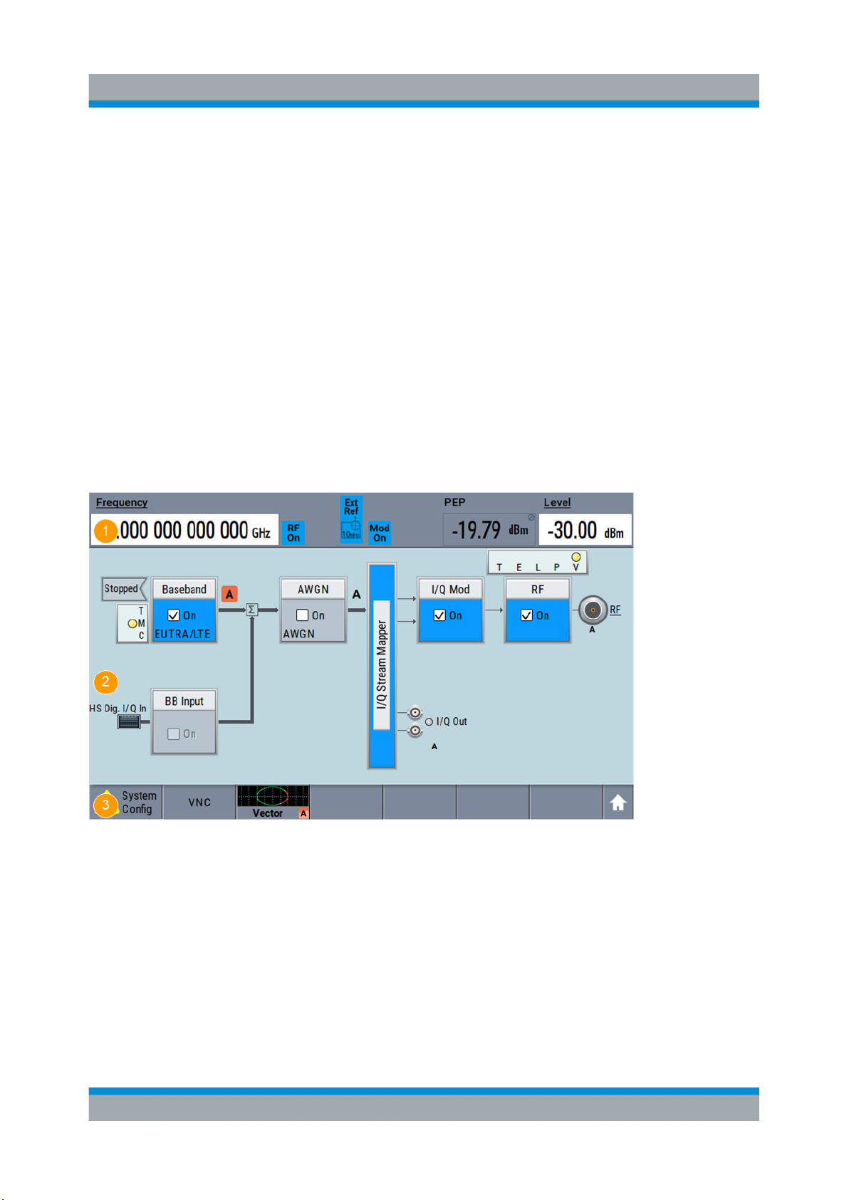
5.1.1 Touchscreen
The block diagram and the most important settings are displayed on the screen
on the front panel. Additionally, the screen display provides status and setting
information and allows you to quickly reconfigure the signal flow. The screen is
touch-sensitive, offering an alternative means of user interaction for quick and
easy handling of the instrument.
Figure 5-2: Touchscreen elements
1 = Status bar (frequency and level display)
2 = Block diagram
3 = Taskbar/softkey bar
A touchscreen is a screen that is touch-sensitive. It reacts in a specified way
when a particular element on the screen is tapped by a finger. Any user interface
element that can be clicked by a mouse pointer can also be tapped on the screen
to trigger the same behavior.
32Getting Started 1423.1049.02 ─ 05
Page 33
R&S®SMBV100B
Instrument Tour
Front Panel Tour
Using the touchscreen, the following tasks (among others) can be performed by
the tap of your finger:
●
Changing a setting
●
Selecting new settings
●
Scrolling through the list of parameters
●
Saving or recalling settings
●
Opening and closing dialogs
See also:
●
Chapter 8, "Instrument Control", on page 73, for operating the touchscreen.
●
"Maintenance" in the user manual, for instructions on cleaning the screen.
5.1.2 Keys
5.1.2.1 Utility Keys
The utility keys cause the R&S SMBV100B to return to a defined instrument state
and provide information on the instrument and assistance.
For more information, refer to chapter "General Instrument Functions" in the user
manual.
Table 5-1: Utility keys
Utility Key Assigned functions
[Preset] Sets the instrument to a defined state
[Save/Rcl] Saves and loads instrument setting
Accesses the file manager
[Local] Switches from remote control to local (manual) control
[Setup] Accesses the general instrument settings
[Help] Displays context-sensitive help text
5.1.2.2 On/Standby
The [On/Standby] key switches the instrument from the standby to the ready state
or vice versa.
33Getting Started 1423.1049.02 ─ 05
Page 34
R&S®SMBV100B
Instrument Tour
Front Panel Tour
The LED above the [On/Standby] key indicates the instrument state, see Chap-
ter 4.13, "Switching On or Off", on page 27.
5.1.2.3 Function Keys
Function keys provide access to most common generator settings and functions.
A detailed description of the corresponding functions is provided in the user manual.
Table 5-2: Function keys
Function key Assigned functions
[Freq] Activates frequency entry.
[Level] Activates level entry.
[Home] Brings the block diagram to the foreground. Active dialogs are
minimized.
[RF on/off] Switches the RF output on and off. Press the key again to restore
the last active status.
Status is displayed in the "Status bar".
[Mod on/off] Switches the modulations on and off. Press the key again to
restore the last active status.
Status is displayed in the "Status bar".
[★ (User)] Key with a customizable function.
5.1.2.4 Keypad
The keypad is used to enter alphanumeric parameters, including the corresponding units. It contains the following keys:
Table 5-3: Keys on the keypad
Type of key Description
Alphanumeric keys Enter numbers and (special) characters in edit dialog boxes.
Decimal point Inserts a decimal point "." at the cursor position.
34Getting Started 1423.1049.02 ─ 05
Page 35
R&S®SMBV100B
Instrument Tour
Front Panel Tour
Type of key Description
Sign key Changes the sign of a numeric parameter. In the case of an
alphanumeric parameter, inserts a "-" at the cursor position.
Unit keys
(G/n dBμV, M/μ μV, k/m mV
and x1 dB(m))
These keys add the selected unit to the entered numeric value
and complete the entry.
In the case of level entries (e.g. in dB) or dimensionless values,
all units have the value "1" as multiplying factor. Thus, they have
the same function as an [Enter] key.
5.1.2.5 Editing Keys
Editing keys enable you to confirm an entry, delete individual characters, or exit
the current operation.
Table 5-4: Editing keys
Type of key Description
[Esc] key Closes all kinds of dialog boxes, if the edit mode is not active.
Quits the edit mode, if the edit mode is active. In dialog boxes
that contain a "Cancel" button it activates that button.
For "Edit" dialog boxes the following mechanism is used:
●
If data entry has been started, it retains the original value
and closes the dialog box.
●
If data entry has not been started or has been completed, it
closes the dialog box.
[Enter] key
[Backspace] key Delets the character to the left of the cursor in editing mode.
Has the same effect as pressing the rotary knob
●
Concludes the entry of dimensionless entries. The new value
is accepted.
●
With other entries, this key can be used instead of the
default unit key.
●
In a dialog box, selects the default or focused element.
●
Calls the next dialog level.
●
Confirms and closes open input windows.
5.1.2.6 Navigation Controls
The navigation controls include a rotary knob, navigation keys, and the display
keys. They allow you to navigate within the display or within dialog boxes.
Rotary Knob
The rotary knob has several functions:
35Getting Started 1423.1049.02 ─ 05
Page 36

R&S®SMBV100B
Instrument Tour
Front Panel Tour
●
Increments (clockwise direction) or decrements (counterclockwise direction)
the instrument parameter at a defined step width in the case of a numeric
entry.
●
Moves the selection, e.g. to a function block in the block diagram
●
Shifts the selection bar within focused areas (e.g. lists).
●
Acts like the [Enter] key, when it is pressed.
●
Opens a context-sensitive menu, when it is pressed and held.
Navigation Keys
The navigation keys can be used alternatively to the rotary knob to navigate
through dialog boxes, diagrams, or tables.
Table 5-5: Navigation keys
Type of key Description
[Up/Down] Key The [Up] and the [Down] key does the following:
●
In a numeric edit dialog box, increase or decrease the instrument parameter.
●
In a list, scroll forward and backward through the list entries.
●
In a table, move the selection bar vertically.
●
In windows or dialog boxes with vertical scrollbar, move the
scrollbar.
[Left/Right] Key The [Left] and the [Right] key does the following:
●
In an alphanumeric edit dialog box, move the cursor.
●
In a list, scroll forward and backward through the list entries.
●
In a table, move the selection bar horizontally.
●
In windows or dialog boxes with horizontal scrollbar, move
the scrollbar.
Display Keys
The display keys arrange different windows on the display.
Table 5-6: Display keys
Display key Assigned functions
[Next window] Toggles between the active dialogs
[Home] Shows the block diagram.
[Next window] Toggles between the open dialogs.
[On/Off Toggle]
●
Switches highlighted elements or a function block on and off.
●
Switches between two or more settings, e.g. items of selection lists. At the end of a list, the cursor is set on the first
entry again.
36Getting Started 1423.1049.02 ─ 05
Page 37
R&S®SMBV100B
Instrument Tour
Front Panel Tour
Display key Assigned functions
[Undo] Reverts the last operation.
[★ (User)] Key with a customizable function.
5.1.3 Connectors
The RF connector and various others interface connectors are on the front panel.
USB
There are two female USB (universal serial bus) connectors of type A (host USB)
on the front panel. These connectors are intended for service and file transfer
purposes only. You can connect, for example, a USB memory stick.
Further USB connectors of type A (host USB) and USB type B (USB In) are available on the rear panel.
How to: Chapter 4.8, "Connecting USB Devices", on page 23.
Sensor
Connector for R&S NRP sensors.
A power sensor is connected to the R&S SMBV100B by inserting the male connector. To disconnect, pull the connector by its sleeve. You cannot disconnect the
sensor simply by pulling at the cable or the rear part of the connector.
The R&S SMBV100B supports the use of R&S NRP power sensors in various
ways including the use as a power viewer.
How to: Chapter "Using Power Sensors" in the user manual
User x
BNC multipurpose connectors for defining input signals and output signals.
The Table 5-7 lists the signals assigned to the User x connectors in the default
instrument state.
Table 5-7: Default configuration of the User x connectors
User connector Direction Default assigned signal
1 Output Baseband Marker 1
2 Output Baseband Marker 2
A dedicated LED indicates the connector status:
●
green: an input connector
37Getting Started 1423.1049.02 ─ 05
Page 38

R&S®SMBV100B
Instrument Tour
Rear Panel Tour
●
yellow: an output connector
●
no light / gray: the connector is not active
See also chapter "Global Connector Settings" in the user manual.
RF
Output for RF signal.
The connector type depends on the installed frequency option.
Table 5-8: Overview of RF connector types depending on the frequency range
Required option Connector type
R&S SMBVB-B103/-KB106 N female
How to: Chapter 4.9, "Connecting to RF", on page 24
5.2 Rear Panel Tour
This section provides an overview of the connectors on the rear panel of the
instrument. For technical data of the connectors, refer to the data sheet.
Figure 5-3: Rear panel
1 = Serial number (six digits in the string 1423.1003.02-<serial number>-<checksum>)
2a, 2b = User x connectors
3a = I/Q, I/Q Bar connectors (output)
3b = I/Q connectors (input)
4 = Dig I/Q connector
5 = HS Dig I/Q connector
6 = Adv Data/Ctrl connector (provided for future use)
7 = LO In/LO Out connectors
38Getting Started 1423.1049.02 ─ 05
Page 39

R&S®SMBV100B
8a = Ref In/Ref Out connectors
8b = Ref In/Ref Out 1GHz connectors
9 = LF connector
10 = Mod Ext connector
11 = Pulse Video connector
12 = Pulse Ext connector
13 = Signal Valid connector
14 = Inst Trig connectors
15 = IEC 625/IEEE 488 connector
16 = Non-Volatile Memory
17, 19 = USB/USB In connectors
18 = LAN connector
20 = AC power supply connection and main power switch
5.2.1 Connectors
Instrument Tour
Rear Panel Tour
User x
BNC multipurpose connectors for defining input signals and output signals.
Table 5-9 lists the signals assigned to the User x connectors in the default instru-
ment state.
Table 5-9: Default configuration of the User x connectors
User connector Direction Default assigned signal
3 Input Global Trigger
4 Input Global Next Segment
5 Output Baseband Sync Out
A dedicated LED indicates the connector status:
●
green: an input connector
●
yellow: an output connector
●
no light / gray: the connector is not active
See also chapter "Global Connector Settings" in the user manual.
I/Q, I/Q Bar
BNC connector for output of direct (single-ended) or differential analog I/Q signals.
Use the connectors for connections as follows:
●
I/Q connectors: Direct (single-ended) or positive differential output of analog
I/Q signals
●
I/Q Bar connectors: Negative differential output of analog I/Q signals
39Getting Started 1423.1049.02 ─ 05
Page 40

R&S®SMBV100B
Dig I/Q
Connectors for the input of a digital I/Q signal from a Rohde & Schwarz instrument, like a signal generator.
HS Dig I/Q
Connectors for the input of high-speed digital I/Q signals, for example, from
Rohde & Schwarz instruments.
For more information, see data sheet.
The interface is a QSFP+ (Quad Small Form-factor Pluggable) module. It supports max. bandwidth of up to 50 Gsample/s with optical active cables.
How to: Chapter 4.12, "Connecting to HS Dig I/Q", on page 26
Adv Data/Ctrl
Interface for exchanging of external data and control signals.
Instrument Tour
Rear Panel Tour
LO In/LO Out
Option: R&S SMBVB-K90
SMA connector for local oscillator input and output for phase-coherent RF signal:
●
LO In: Input of phase coherence signal
●
LO Out: Output of phase coherence signal
How to: Chapter 4.10, "Connecting to LO In/Out", on page 24
I/Q
BNC connector for input of external I/Q signals for analog modulation. The signals
are fed directly into the I/Q modulator.
Use the I/Q connector for direct (single-ended) or positive differential input of analog I/Q signals.
See also chapter "Overview of the Input and Output Signals and Connectors" in
the user manual.
Ref In/Ref Out
Input/output for external reference signal.
BNC connectors for reference signals from 1 MHz to 100 MHz.
SMA connectors for 1 GHz reference signals.
How to: Chapter 4.11, "Connecting to Ref In/Ref Out", on page 25
LF
Output for internal LF generator signal.
40Getting Started 1423.1049.02 ─ 05
Page 41

R&S®SMBV100B
See also data sheet and user manual, section "Analog Modulation".
Mod Ext
Input for external analog modulation signals.
Pulse Video
Output of the internal pulse generator signal or the looped through pulse signal
from Pulse Ext connector (video signal).
Pulse Ext
Input for an external pulse modulation signal or an external trigger/gate signal for
the pulse generator.
Signal Valid
Output signal that marks the valid signal times (valid level and frequency) for all
analog modulations.
Instrument Tour
Rear Panel Tour
Inst Trig
BNC connector for input of external trigger signals. The signals trigger sweeps
and list mode.
See chapter "Signal Generation and Triggering in the Sweep and List Modes" in
the user manual.
IEC 625/IEEE 488
General purpose interface bus (GPIB) interface for remote control of the instrument. The interface is in compliance with the standards IEC 625, IEEE 488 and
SCPI.
Use this interface to connect a computer for remote control of the
R&S SMBV100B. To set up the connection, use high-quality shielded cables. See
"Cable selection and electromagnetic interference (EMI)" on page 20.
See also "Annex: Hardware Interfaces" and chapter "Network and Remote Control" in the user manual.
Non-Volatile Memory
Option: R&S SMBVB-B80
Slot for removable mass storage.
41Getting Started 1423.1049.02 ─ 05
Page 42

R&S®SMBV100B
USB/USB In
●
Female USB type A connector, to connect devices like a keyboard, a mouse,
a memory stick, or the R&S NRP-Z3/Z4 cable for the R&S NRP power sensors
●
Female USB In connector (USB type B), for example for remote control.
How to: Chapter 4.8, "Connecting USB Devices", on page 23
LAN
RJ-45 connector to connect the R&S SMBV100B to a LAN for remote control,
remote operation, and data transfer.
How to: Chapter 4.7, "Connecting to LAN", on page 22
AC power supply connector and switch
Mains power switch for performing the following tasks:
●
Connecting the internal power supply to the power source
●
Disconnecting the internal power supply from the power source
Instrument Tour
Rear Panel Tour
How to: Chapter 4.6, "Connecting to Power", on page 22.
42Getting Started 1423.1049.02 ─ 05
Page 43

R&S®SMBV100B
Generating an Unmodulated Carrier
Trying Out the Instrument
6 Trying Out the Instrument
This chapter introduces the most important functions and settings of the
R&S SMBV100B step by step. The complete description of the functionality and
its usage is given in the R&S SMBV100B user manual. Basic instrument operation is described in Chapter 8, "Instrument Control", on page 73.
Prerequisites
●
The instrument is set up, connected to the power supply, and started up as
described in Chapter 4, "Preparing for Use", on page 17.
For the first signal generation tasks, you use the internal baseband and reference
signal, so you do not need any additional signal source. More complex signal
generation tasks, however, require an instrument equipped with additional options
and/or external signals. Each task description lists its prerequisites.
The screenshots in this description show a fully equipped instrument. Consider that, the block diagram displayed on your particular instrument can differ from the one used in the example.
The instrument is manually operated via the touchscreen. Try out the following:
● Generating an Unmodulated Carrier...............................................................43
● Generating a Digitally Modulated Signal.........................................................46
● Triggering the Instrument with an External Signal...........................................48
● Enabling and Configuring a Marker Signal......................................................54
● Verifying the Generated Signal with the Graphics Display..............................55
● Saving and Recalling Settings........................................................................ 58
● Generating an EUTRA/LTE Signal.................................................................. 61
6.1 Generating an Unmodulated Carrier
We start out by generating a simple unmodulated signal. The R&S SMBV100B in
this example can be a base unit in its minimal configuration (i.e. with installed
R&S SMBVB-B103).
43Getting Started 1423.1049.02 ─ 05
Page 44
R&S®SMBV100B
Generating an Unmodulated Carrier
1. On the R&S SMBV100B front panel, press the Preset key to start out in a
defined instrument configuration.
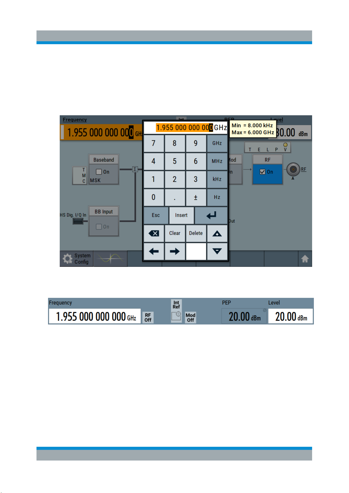
2. Set the frequency:
a) On the "Status Bar", tap the "Frequency" field.
b) On the on-screen keypad, enter 1.955 and press the "GHz" key.
Trying Out the Instrument
The on-screen keypad closes and the frequency value is displayed.
3. On the "Status Bar", tap the "Level" field and enter the level in the same way.
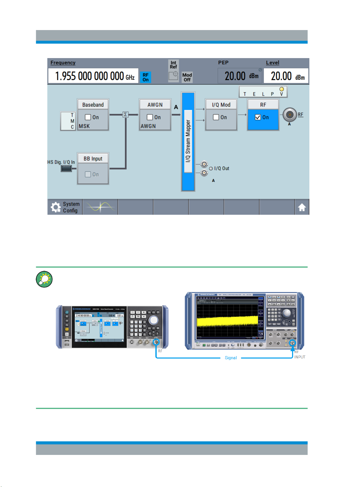
4. Select "Block Diagram > RF Block > On" to enable the output of the generated
unmodulated signal.
44Getting Started 1423.1049.02 ─ 05
Page 45
R&S®SMBV100B
Trying Out the Instrument
Generating an Unmodulated Carrier
Figure 6-1: Block diagram: Generating an unmodulated signal
The 1.95 GHz signal is output at the RF connector at the front panel of the
R&S SMBV100B.
Connect RF of the R&S SMBV100B to a signal analyzer, for example
R&S®FSW, to display the generated signal.
Figure 6-2: Simplified test setup
For the required settings of the signal analyzer, refer to its user manual or
its online help.
45Getting Started 1423.1049.02 ─ 05
Page 46
R&S®SMBV100B
Generating a Digitally Modulated Signal
Trying Out the Instrument
6.2 Generating a Digitally Modulated Signal
This example shows you how to generate a simple WCDMA-3GPP (QPSK 45°
offset) signal with the help of the "Custom Digital Modulation" functionality.
The minimum requirement for R&S SMBV100B in this example is a base unit
equipped with:
●
Option custom digital modulation R&S SMBVB-K520
●
Option frequency R&S SMBVB-B103.
The initial situation is not the instrument's preset state but rather the configuration
described in Chapter 6.1, "Generating an Unmodulated Carrier", on page 43.
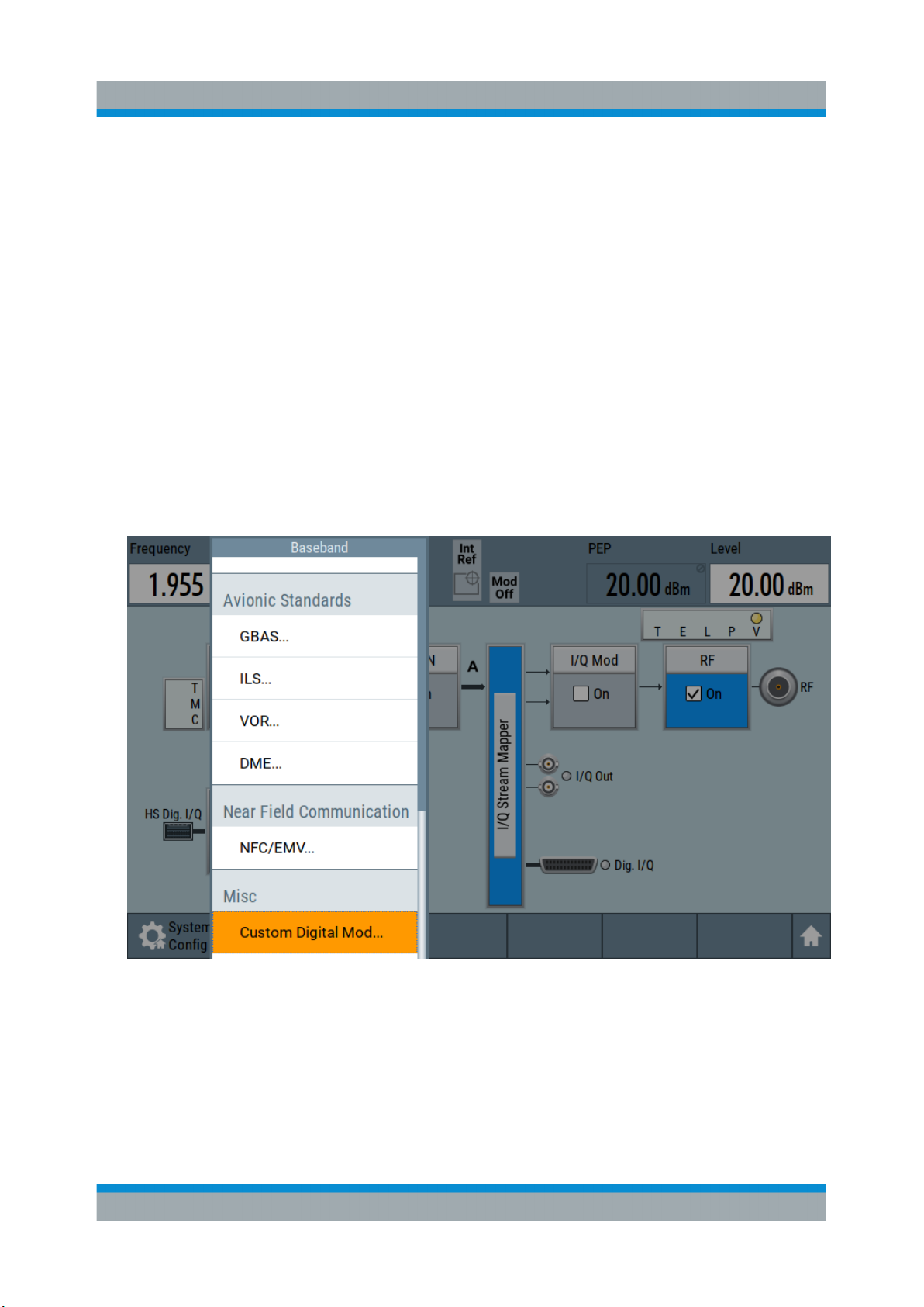
1. In the block diagram, select "Baseband" and navigate to the section "Misc >
Custom Digital Mod...".
The "Custom Digital Modulation" dialog opens.
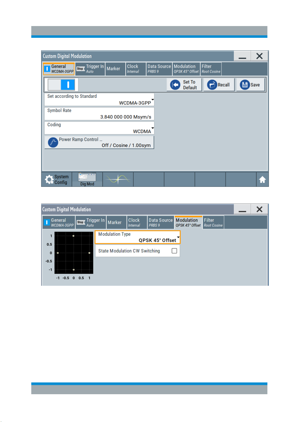
2. In the "Custom Digital Modulation" dialog, select "General > Set according to
Standard > WCDMA-3GPP".
3. Select "General > State > On" to enable signal generation.
46Getting Started 1423.1049.02 ─ 05
Page 47
R&S®SMBV100B
Trying Out the Instrument
Generating a Digitally Modulated Signal
4. Select the "Modulation" tab and observe the used "Modulation Type".
Figure 6-3: Display of the used modulation type
The instrument activates automatically "I/Q Mod", uses the internal trigger and
clock signals, and generates a WCDMA-3GPP signal, modulated with a
QPSK 45° offset modulation.
47Getting Started 1423.1049.02 ─ 05
Page 48

R&S®SMBV100B
Trying Out the Instrument
Triggering the Instrument with an External Signal
Figure 6-4: Block diagram: Generating a digitally modulated signal
6.3 Triggering the Instrument with an External Sig-
nal
The example configurations are rather theoretical cases, because you rarely use
the R&S SMBV100B as a standalone instrument. Usually, the instrument would
be connected to a device under test (DUT) and/or other measurement equipment.
As a rule, whenever a test setup requires two or more devices, provide them with
a common reference frequency. Some test setups require control of the signal
generation start and an exact generation start time, determined by a defined trigger event. For example, by triggering the instrument internally or externally from
the DUT.
This example illustrates the general principle of external triggering and extends
the configuration performed in Chapter 6.2, "Generating a Digitally Modulated
Signal", on page 46 by the configuration of the required trigger signal and con-
nector settings.
This test setup requires one signal analyzer, like the R&S®FSW, as additional
equipment.
48Getting Started 1423.1049.02 ─ 05
Page 49
R&S®SMBV100B
Triggering the Instrument with an External Signal
To start the signal generation synchronous to an external global trigger signal
The configuration requires three main steps with the following goals:
1. Observe the current connector configuration. Define an input connector for the
external global trigger signal.
See "To verify the current connector configuration" on page 49
2. Configure the baseband to use this external global trigger signal as trigger
source.
See "To reconfigure the trigger settings" on page 51
3. Connect the instrument and the external trigger source.
See "To connect the instrument and the external trigger source" on page 53
To verify the current connector configuration
Trying Out the Instrument
The R&S SMBV100B is equipped with multipurpose bi-directional User connectors. Because the signal direction, input or output, and the signal mapping are
configurable, we recommend that you check the current configuration before
cabling or further instrument's configurations.
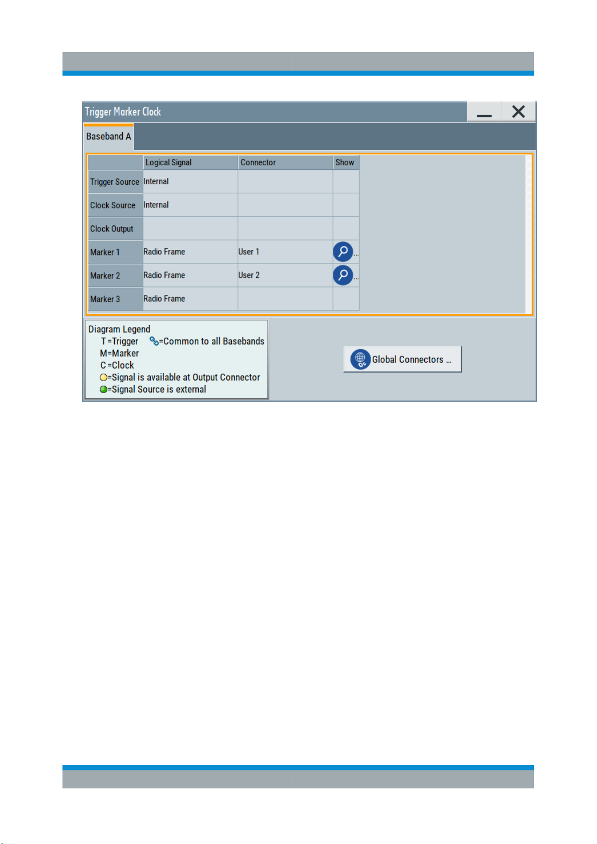
1. To display an overview of the current mapping of the logical signals to the connectors, perform one of the following:
● In the block diagram, select the Trigger/Marker/Clock status LEDs on the
left side of the "Baseband" block.
● Select "Baseband > Trigger Marker Clock".
49Getting Started 1423.1049.02 ─ 05
Page 50
R&S®SMBV100B
Trying Out the Instrument
Triggering the Instrument with an External Signal
The instrument uses its internal trigger and clock signals, and the default mapping of the marker signals to the connectors.
2. To access the related connector settings, perform one of the following:
● Select "Global Connector Settings"
● Tap the connector name, for example select the connector "User 1"
50Getting Started 1423.1049.02 ─ 05
Page 51

R&S®SMBV100B
Triggering the Instrument with an External Signal
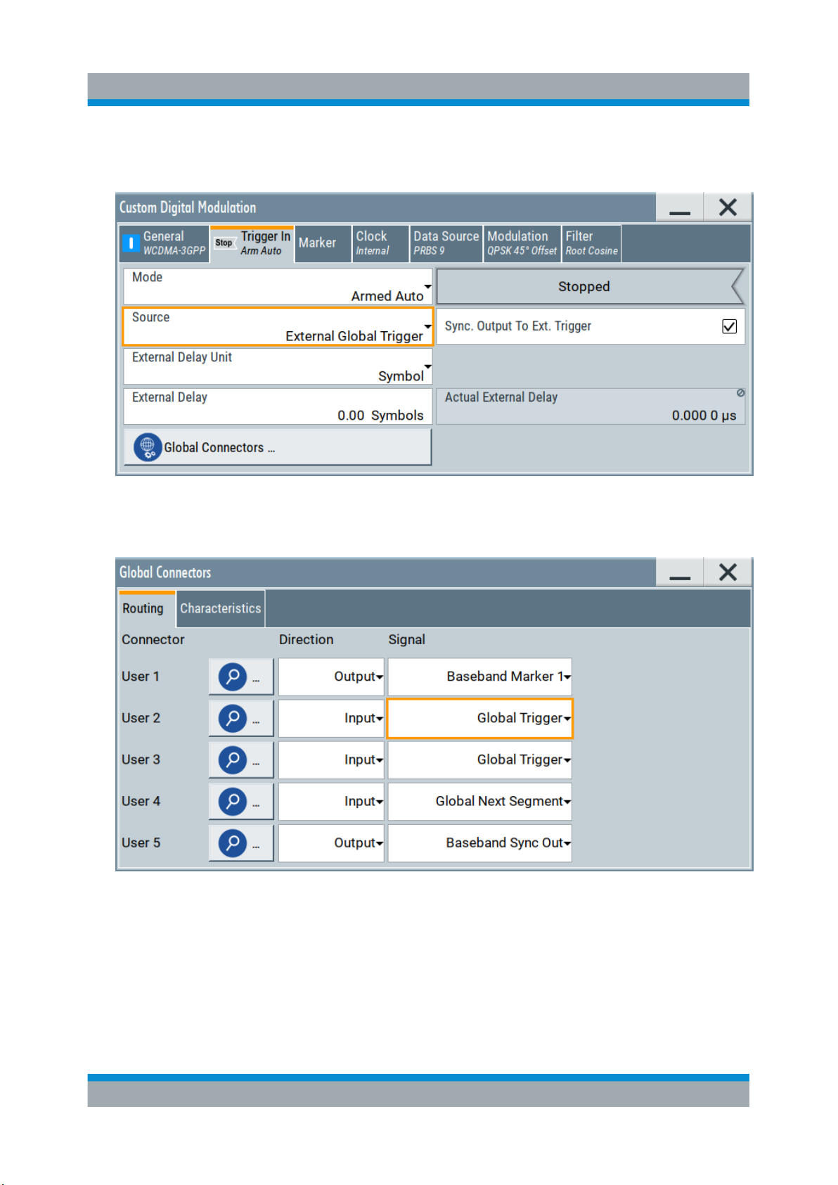
Figure 6-5: Signal mapping to the global connectors
Trying Out the Instrument
The "Global Connectors" dialog displays the current connectors configuration.
The settings are configurable, but in this example we use the default mapping.
3. Alternatively, select "Block Diagram > Baseband > Misc > Custom Digital
Mod", select the "Trigger In" tab and select "Global Connector Settings".
In the current mapping, the two global connectors User x on the front panel
are configured as follows:
● "Marker 1/2" are output at the User 1/2 connectors
● The User 3 connector is an input for the "Global Trigger" signal.
Find the physical location of each connector
Use the built-in "Trigger Marker Clock > Show" function to display the location of the selected connector. A blinking marker on the front/rear panel
view also indicates the selected connector.
To reconfigure the trigger settings
We assume that the instrument is configured as described in Chapter 6.2, "Gen-
erating a Digitally Modulated Signal", on page 46 and the default connector map-
ping is maintained (see Figure 6-5).
1. In the block diagram, select "Baseband > Misc > Custom Digital Mod > Trigger
In".
2. Select the following settings:
51Getting Started 1423.1049.02 ─ 05
Page 52
R&S®SMBV100B
Triggering the Instrument with an External Signal
a) "Mode > Armed Auto"
b) "Source > External Global Trigger".
Trying Out the Instrument
3. Select "Global Connector Settings > Routing".
4. For "User 2", select "Direction > Input" and "Signal > Global Trigger".
The instrument expects an external global trigger event. In the current configuration, the "Global Trigger" signal has to be supplied at the input connector
User 2.
The Trigger/Marker/Clock status LEDs in the block diagram confirm that an
external trigger signal is selected; the signal generation is however stopped.
52Getting Started 1423.1049.02 ─ 05
Page 53

R&S®SMBV100B
Trying Out the Instrument
Triggering the Instrument with an External Signal
To connect the instrument and the external trigger source
1. Use a suitable cable to connect the external trigger source to the User 2 connector of the R&S SMBV100B. See Figure 6-6.
Figure 6-6: Simplified representation of a test setup**
** = The figure depicts the cabling as a general principle; particular test setups do not require
all connections at the same time
The Figure 6-6 depicts the location of the connectors and explains the connection as principle. In practice, you would rather "substitute" the analyzer by
a DUT, like a base station (BS). Other than in the example, the DUT can be
the source for the reference signal. Instead of using an external trigger
source, the DUT can also send, for example, a frame trigger signal to the
R&S SMBV100B. The R&S SMBV100B acts still as the signal source.
53Getting Started 1423.1049.02 ─ 05
Page 54
R&S®SMBV100B
Enabling and Configuring a Marker Signal
2. Use suitable cables to connect the RF and REF OUT connectors of the
R&S SMBV100B to the signal analyzer or the DUT.
Upon the receiving of an external trigger event, the R&S SMBV100B starts the
signal generation and then generates a continuous signal. An "Arm" stops the
signal generation. A subsequent trigger event causes a restart of the signal
generation.
To learn more about this topic, refer to:
●
Chapter "Baseband Trigger Signals" in the user manual
●
Chapter "Global Connectors" in the user manual
Trying Out the Instrument
6.4 Enabling and Configuring a Marker Signal
Test setups often require that an external device is synchronized to the generated
data stream. For this purpose, the R&S SMBV100B can output marker signals (or
markers) also to the generated signal. The R&S SMBV100B provides several regular marker signals and marker signals specific to the firmware option. With suitable marker settings for instance, you can mark slot or frame boundaries or mark
the start of a particular modulation symbol.
This example extends further the configurations performed in Chapter 6.2, "Gen-
erating a Digitally Modulated Signal", on page 46. We assume a default connector
mapping (see Figure 6-5).
This test setup requires one oscilloscope, like the R&S®RTO, as additional equipment.
1. In the block diagram, select "Block Diagram > Baseband > Misc > Custom
Digital Mod > Marker" tab.
2. Select "Marker Mode > Marker 1 > Pulse" and "Divider = 32".
Generated is a periodic marker with marker frequency of 120 KHz. The signal
is output at the User 1 connector of the R&S SMBV100B (see Figure 6-5).
3. Use a suitable cable to connect the User 1 connector of the R&S SMBV100B
to the monitoring instrument, for example oscilloscope like R&S®RTO. See
Figure 6-7.
54Getting Started 1423.1049.02 ─ 05
Page 55

R&S®SMBV100B
Verifying the Generated Signal with the Graphics Display
Figure 6-7: Simplified representation of a test setup for signal monitoring**
** = The figure depicts the cabling as a general principle
4. Use a suitable cable to connect the I OUT connector of the R&S SMBV100B
to the monitoring instrument.
Trying Out the Instrument
To learn more about this topic, refer to chapter "Regular Marker Output Signals" in the user manual.
6.5 Verifying the Generated Signal with the Graph-
ics Display
It is often useful to check the spectra of the configured signals, before you enable
the RF output of the instrument.
The R&S SMBV100B provides a build-in function to represent the generated signal on a graphical signal display. We demonstrate this feature by showing the
characteristics at one particular point of the signal processing chain. You can,
however, display the signal characteristics at other different stages.
This example shows you how to use this graphical display to verify the generated
signal. Use the signal generated in Chapter 6.4, "Enabling and Configuring a
Marker Signal", on page 54.
To access the graphical signal display functionality
► Perform one of the following:
55Getting Started 1423.1049.02 ─ 05
Page 56

R&S®SMBV100B
Verifying the Generated Signal with the Graphics Display
a) Select "Taskbar > System Configuration > Graphics"
b) On the "Taskbar", tap the wave icon.
Trying Out the Instrument
The "Graphics Configuration" dialog opens.
To visualize the signal
1. In the "Graphics Configuration" dialog, select "Mode > Constellation".
2. Select "Source > Baseband".
3. Select "Add" to enable signal display.
56Getting Started 1423.1049.02 ─ 05
Page 57

R&S®SMBV100B
Verifying the Generated Signal with the Graphics Display
A new thumbnail (minimized view) indicating the active diagram appears in
the "Taskbar".
4. Press the thumbnail graphic.
The graphic enlarges and the diagram is displayed in a normal size.
Trying Out the Instrument
The "Constellation Diagram" displays the 3GPP FDD signal.
5. To retrieve more information, zoom in. In some diagrams you can select
"Show Marker" to measure the distance, for example, between two signals.
In principle, the zoom in function works like the two-finger pinching for magnifying images on your cellphone.
6. In the "Constellation Diagram" dialog, select "Configure" to return to the
"Graphics Configuration" dialog.
Close the "Graphics Configuration" dialog.
This action has no effect on the configured graphics but on the dialog itself.
The block diagram displays the current signal routing. It indicates that frequency and power offsets are enabled and displays the acquisition points for
the real-time diagrams minimized in the "Taskbar".
57Getting Started 1423.1049.02 ─ 05
Page 58

R&S®SMBV100B
Trying Out the Instrument
Saving and Recalling Settings
6.6 Saving and Recalling Settings
To restore the results of our measurements later, we save the instrument settings
to a file.
To save the instrument settings to a file
We assume, a test configuration as described in Chapter 6.4, "Enabling and Con-
figuring a Marker Signal", on page 54.
1. Press the Save/Rcl key on the front panel.
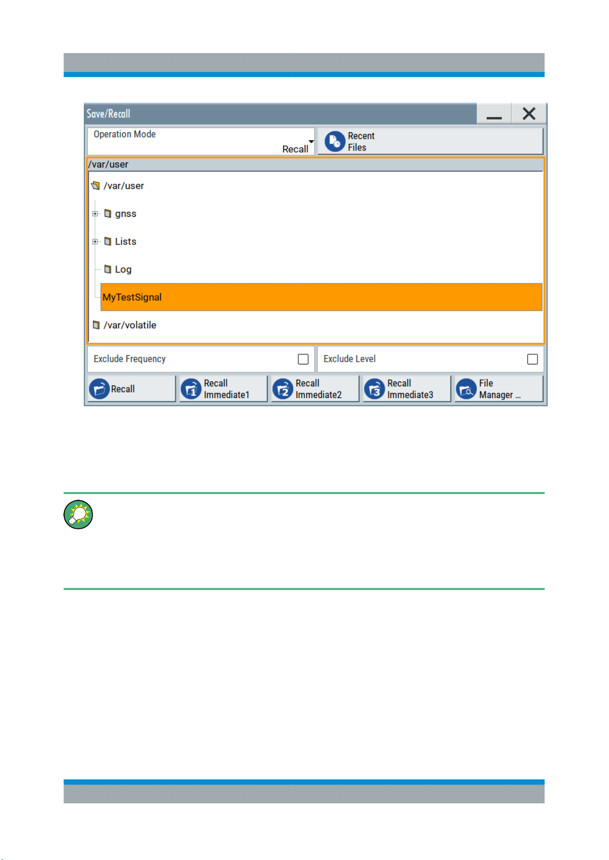
2. In the "Save/Recall" dialog box, select "Operation Mode > Save".
Tap the "Filename", use the on-screen keyboard, and enter MyTestSignal.
58Getting Started 1423.1049.02 ─ 05
Page 59

R&S®SMBV100B
3. Tap the "Save" button.
The file MyTestSignal.savrcltxt is saved in the default directory /var/
user.
Trying Out the Instrument
Saving and Recalling Settings
To load saved instrument settings
You can restore the settings to the instrument at any time using the settings file.
1. Press the Preset button to restore the default instrument settings so you can
check that the saved user settings are restored afterwards.
2. Press the Save/Rcl key.
3. In the "Save/Recall" dialog, select "Recall" operation.
Navigate to the directory of the saved file. Select the MyTestSignal file.
59Getting Started 1423.1049.02 ─ 05
Page 60
R&S®SMBV100B
Trying Out the Instrument
Saving and Recalling Settings
4. Tap the "Recall" button.
All instrument settings are restored and the display resembles the instrument
display right before the settings were saved.
How to display all parameters with values different to their preset values
When you load a file to your instrument and do not have enough information on the changed settings, visualize all parameters that have been
changed from their default state.
Try out the following:
●
Tap and hold on an empty space in the block diagram to access the contextsensitive menu.
●
Select "Mark All Parameters Changed from Preset".
60Getting Started 1423.1049.02 ─ 05
Page 61
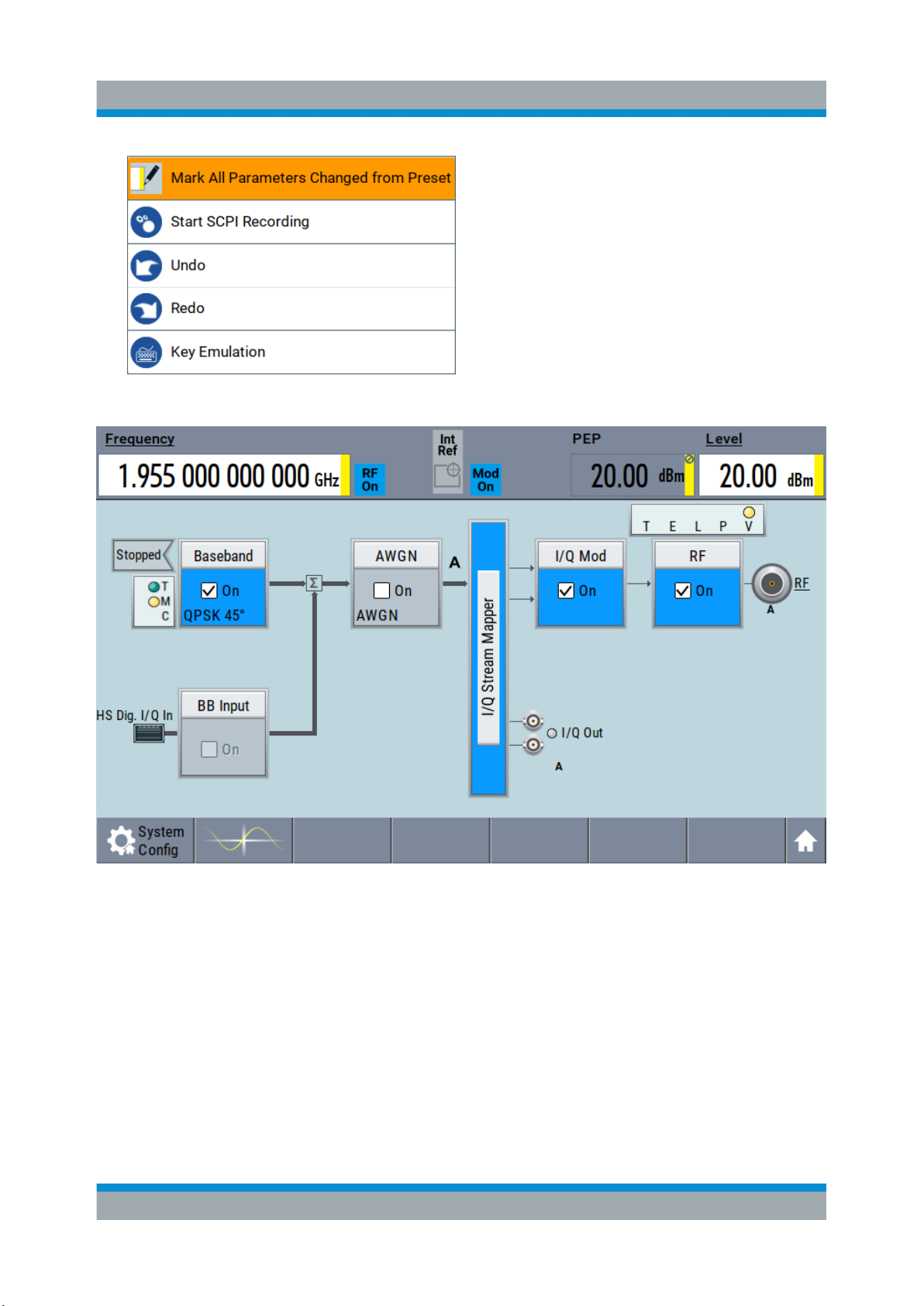
R&S®SMBV100B
●
All changed parameters are highlighted.
Trying Out the Instrument
Generating an EUTRA/LTE Signal
6.7 Generating an EUTRA/LTE Signal
The main application field of the R&S SMBV100B is the generation of digital signals in accordance with several telecommunication and wireless standards, like
WCDMA, EUTRA/LTE or WLAN, to name a few. This example uses the digital
standard EUTRA/LTE to introduce the way you can access and interact with the
instrument and experience the advantages provided by the additional options.
61Getting Started 1423.1049.02 ─ 05
Page 62

R&S®SMBV100B
Generating an EUTRA/LTE Signal
The minimum requirement for R&S SMBV100B in this example is a base unit
equipped with:
●
Option EUTRA/LTE R&S SMBVB-K55
●
Option frequency R&S SMBVB-B103
To generate a downlink test signal
The main focus of the following example is not on the R&S SMBV100B capabilities and the features provided by the firmware option. The example aims rather to
help you get familiar with the settings and configuration principle common for the
digital standards.
We use one of the provided EUTRA test models (E-TM) to show how to generate
a test signal upon a quick selection.
1. On the R&S SMBV100B front panel, press the Preset key to start out in a
defined instrument configuration.
Trying Out the Instrument
2. In the block diagram, select "Baseband > Beyond 3G Standards > EUTRA/
LTE".
The EUTRA/LTE dialog appears and displays the general settings provided for
the digital standard.
62Getting Started 1423.1049.02 ─ 05
Page 63

R&S®SMBV100B
Generating an EUTRA/LTE Signal
As in the user interfaces of all digital standards, the "EUTRA/LTE" dialog is
divided into several tabs. The "General" tab comprises the primary settings of
the standard, the functions for storing and recalling settings and provides
access to further functions and dialogs, like the "Filter" settings. The "Trigger
In", "Marker" and "Clock" tabs comprise the settings related to the corresponding function.
The more complex the digital standard itself is, the more comprehensive the
further dialog and tab structure. The start dialog of each digital standard, however, follows a repeating dialog structure that comprises the tabs "General",
"Trigger In", "Marker" and "Clock". (See also Chapter 8.3.4, "Additional Dis-
play Characteristics", on page 78).
Tip: To display the dialog in its maximal height, press the Resize window key
on the front panel.
3. In the "EUTRA/LTE General" tab, select "Test Models".
The test models is a function for quick selection and settings adjustment
according to one of the various EUTRA test models (E-TM).
Trying Out the Instrument
A standard "File Select" function enables you to select form files with predefined settings.
Tip: On the front panel, press the Help key to retrieve detailed information on
the current settings and on the contents of the predefined files.
4. Navigate to a file, for example to the E-TM1_1__10MHz (an E-TM1.1 test
model with 10 MHz channel bandwidth) and confirm with "Select".
63Getting Started 1423.1049.02 ─ 05
Page 64
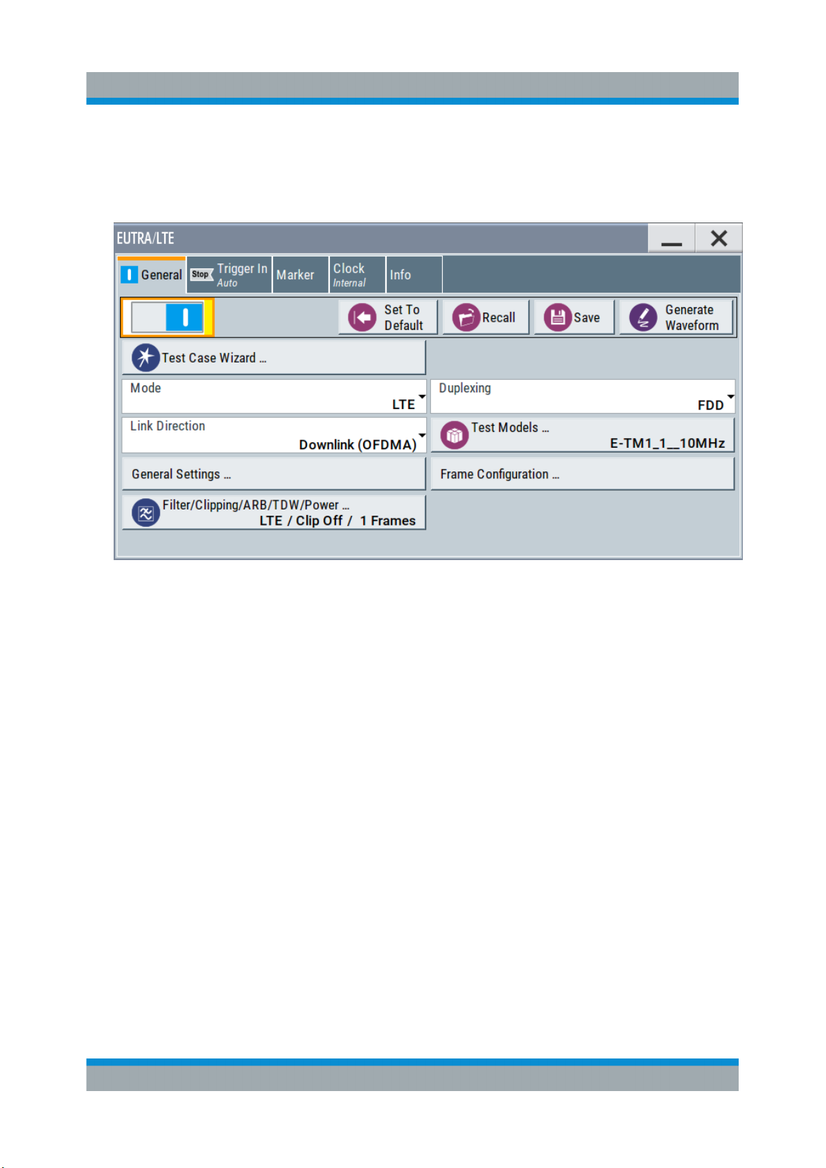
R&S®SMBV100B
Generating an EUTRA/LTE Signal
The dialog closes automatically and the user interface confirms the name of
the selected file.
5. In the "EUTRA/LTE > General" tab, select "State > On".
Trying Out the Instrument
Close the dialog.
6. On the "Status Bar", tap the "Frequency" and "Level" fields and enter new values, for example 2.1432 GHz and -20 dBm.
64Getting Started 1423.1049.02 ─ 05
Page 65

R&S®SMBV100B
Select "RF > On".
Trying Out the Instrument
Generating an EUTRA/LTE Signal
The instrument generates an EUTRA/LTE test signal with the selected channel bandwidth, frequency, and level.
With these first steps, you have gained an impression of the provided functionality.
For a comprehensive description of the full range of capabilities, refer to the
user manual "EUTRA/LTE Digital Standard for R&S SMBV100B".
65Getting Started 1423.1049.02 ─ 05
Page 66

R&S®SMBV100B
Trying Out the Instrument
Generating an EUTRA/LTE Signal
66Getting Started 1423.1049.02 ─ 05
Page 67

R&S®SMBV100B
System Overview
Signal Flow at a Glance
7 System Overview
This section helps you to get familiar with the R&S SMBV100B. It provides an
introduction to the general concept of the instrument. This section also introduces
the main blocks in the signal generation flow.
For information on how to access functions and interact with the
R&S SMBV100B, refer to Chapter 8, "Instrument Control", on page 73.
7.1 Brief Introduction to the Instrument's Concept
The R&S SMBV100B offers excellent RF and baseband characteristics. The
baseband section of the R&S SMBV100B is fully digital. It contains the hardware
for generating and processing I/Q signals in realtime or generating signals with an
arbitrary waveform generator.
7.2 Signal Flow at a Glance
The R&S SMBV100B is equipped with a large touchscreen, that displays a block
diagram. The block diagram represents the signal flow and the general stages the
signal generation goes through. Depending on the options the R&S SMBV100B is
equipped with, the appearance of the block diagram changes.
The following examples do not cover all possible cases but aim to introduce the
way the block diagram depicts the installed options.
●
An example of a base unit, equipped with R&S SMBVB-B103.
67Getting Started 1423.1049.02 ─ 05
Page 68

R&S®SMBV100B
●
An example of a fully equipped instrument.
The block diagram displays all blocks for that the required hardware and software options are fitted. The block diagram shows the signal flow as it is.
System Overview
Signal Flow at a Glance
The cross-reference between the installed options and the displayed settings
The Table 7-1 is an excerpt of the available options and lists only the options
required to display a functional block in the block diagram. The information
assumes R&S SMBV100B base unit.
For exact information on the available options, and on the minimum requirements
and the interdependencies between the provided options, refer to the
R&S SMBV100B data sheet.
68Getting Started 1423.1049.02 ─ 05
Page 69

R&S®SMBV100B
Digital Baseband Input ("BB Input"Block)
Table 7-1: Required options per functional block (excerpt)
Functional block Required option
"Baseband" -
System Overview
"BB Input"
"AWGN" R&S SMBVB-K62
"I/Q Stream Mapper" -
"I/Q Mod" -
"I/Q Analog" -
"RF" R&S SMBVB-B103/-KB106
7.3 Internal Baseband Source ("Baseband" Block)
The "Baseband" block represents the source of the baseband signals (basebands).
This functional block is the access point to:
●
The internal baseband generator
The baseband generator contains modules for real time signal generation
(Custom Digital Modulation) and an arbitrary waveform generator (ARB).
●
The available digital standards
Generation of digital signals in accordance with the supported standards
requires additional software options. For example, option R&S SMBVB-K55
generates signals according to the EUTRA/LTE standard.
●
The baseband offsets function
Signals from the baseband generator can be shifted in frequency and phase,
or boosted in power.
7.4 Digital Baseband Input ("BB Input"Block)
The "BB Input" block is the access point to the settings of the digital interfaces.
The R&S SMBV100B is able to receive and process digital baseband signals.
The digital baseband input can be used together with other Rohde & Schwarz
instruments, like signal generators. Note, however, that the internal and the exter-
69Getting Started 1423.1049.02 ─ 05
Page 70

R&S®SMBV100B
I/Q Modulator ("I/Q Mod" Block)
nal digital signals cannot be used simultaneously. The two blocks "Baseband"
and "BB Input" deactivate each other.
The "BB Input" block is the access point to the settings of:
●
The external digital I/Q signals
The external digital I/Q signals are further processed in the baseband section
●
The baseband offsets function
The external and internal baseband signals can be shifted in frequency and
phase, or boosted in power.
System Overview
7.5 Additional White Gaussian Noise ("AWGN"
Block)
The "AWGN" block is displayed only in instruments equipped with the option
R&S SMBVB-K62. This block controls the additional white Gaussian noise generator (AWGN). An additive white noise is required for measurements of mobile
radio base stations.
7.6 "I/Q Stream Mapper" Block
As one of the access points to the system configuration settings, the "I/Q Stream
Mapper" provides direct access for mapping the generated I/Q streams to the
available output connectors. That is, to the analog RF and I/Q output connectors.
7.7 I/Q Modulator ("I/Q Mod" Block)
The "I/Q Mod" block represent the I/Q modulator.
This functional block is the access point to:
●
The I/Q modulation of the internal baseband signal
●
The I/Q modulation of an external single-ended analog wideband signal
●
The analog I/Q impairments
70Getting Started 1423.1049.02 ─ 05
Page 71

R&S®SMBV100B
Applications Examples of the R&S SMBV100B
System Overview
7.8 Analog I/Q Output ("I/Q Analog" Block)
The "I/Q Analog" block represents the analog I/Q output connectors.
This block is the access point to the settings of:
●
The analog I/Q output signals
The generated signal can be output as single-ended or differential analog signal.
●
The analog I/Q impairments
7.9 RF and Analog Modulations ("RF" Block)
The "RF" block represents the RF settings of the instrument.
This block is the access point to:
●
RF frequency and level settings, as well as the reference frequency, local
oscillator, user correction, etc.
●
The analog modulations
●
The list and sweep modes
7.10 Applications Examples of the R&S SMBV100B
The R&S SMBV100B can be optimally adapted to the requirements of different
applications:
●
Generation of digitally modulated signal
The main field of application of the R&S SMBV100B is the generation of digitally modulated signals. The R&S SMBV100B generates a digitally modulated
signal in several ways: using the internal baseband generator, using the externally applied digital baseband signals or in an analog wideband I/Q operation.
●
Generation of a wanted signal or an interfering signal for receiver tests
●
Generation of signals with up to 500 MHz signal bandwidth
71Getting Started 1423.1049.02 ─ 05
Page 72

R&S®SMBV100B
System Overview
Applications Examples of the R&S SMBV100B
72Getting Started 1423.1049.02 ─ 05
Page 73

R&S®SMBV100B
Possible Ways to Operate the Instrument
Instrument Control
8 Instrument Control
This chapter provides an overview on how to work with the R&S SMBV100B.
It covers the following topics:
● Possible Ways to Operate the Instrument.......................................................73
● Means of Manual Interaction...........................................................................74
● Understanding the Display Information...........................................................75
● Accessing the Functionality.............................................................................80
● Entering Data.................................................................................................. 82
● Getting Information and Help.......................................................................... 83
● Remote Control...............................................................................................85
● Remote Operation over VNC.......................................................................... 86
8.1 Possible Ways to Operate the Instrument
There are three ways to operate the R&S SMBV100B:
●
Manual operation:
Use the touchscreen, hard keys and rotary knob, or an optional mouse and/or
keyboard.
The following description shows how to operate the instrument manually.
●
Remote control:
Create programs to automatize repeating settings, tests and measurements.
The instrument is connected to a computer running the program.
This way of operation is described in the user manual, chapter "Network and
Remote Control Operation".
●
Remote operation from a computer:
Remote monitoring and control of the instrument from a connected computer
is based on the common cross-platform technology VNC (Virtual Network
Computing). On the remote computer, any standard web browser (supporting
Java) or a dedicated VNC client (like Ultr@VNC) can be used. See also Chap-
ter 8.8, "Remote Operation over VNC", on page 86.
73Getting Started 1423.1049.02 ─ 05
Page 74

R&S®SMBV100B
Means of Manual Interaction
Instrument Control
8.2 Means of Manual Interaction
For the manual interaction with the R&S SMBV100B, you have several methods
that you can use as an alternative to perform a task:
●
Touchscreen:
Touchscreen operation is the most direct way to interact. Almost all control
elements and actions on the screen are based on the standard operating system concept. You can tap any user interface element to set parameters in dialog boxes, enter data, scroll within a dialog etc., as if you work with a mouse
pointer.
Tapping the screen works like clicking mouse buttons:
– Touch quickly = click: Selects a parameter or provokes an action.
– Touch and hold = right-click: Opens a context-sensitive menu.
– Touch and swipe = drag: Scrolls through the contents of a display element
larger than the screen, e.g. a list or a table.
– Spread or pinch two fingers = zoom out, zoom in:
Increases or decreases the size of an area in a graphical display as it
works on your cell phone
●
Function keys and rotary knob:
The front panel provides nearly all functions and controls to operate the instrument in the classic way, without touchscreen.
●
Optional mouse and/or keyboard:
These devices work like known from PCs. The navigation keys on the front
panel correspond to the keys on the keyboard.
This manual describes the manual interaction with the instrument via the touchscreen. It mentions the alternative methods using the keys on the instrument or
the on-screen keypads if it deviates from the standard operating procedures. The
usage of the touchscreen and navigation keys is described in Chapter 8.4,
"Accessing the Functionality", on page 80.
Throughout the manual, the term "select" refers to any of the described methods,
i.e. using a finger on the touchscreen, a mouse pointer in the display, or a key on
the instrument or on a keyboard.
74Getting Started 1423.1049.02 ─ 05
Page 75

R&S®SMBV100B
Instrument Control
Understanding the Display Information
8.3 Understanding the Display Information
The block diagram of the R&S SMBV100B displays all main settings and generator states, divided into three main operation areas.
Figure 8-1: Block diagram
1 = Status bar (frequency and level display)
2 = Block diagram
3 = Taskbar/softkey bar
● Status Bar....................................................................................................... 75
● Block Diagram.................................................................................................76
● Taskbar............................................................................................................77
● Additional Display Characteristics...................................................................78
8.3.1 Status Bar
The status bar at the top of the screen indicates the RF frequency and the level of
the output signal provided to the DUT. You can set both parameters directly here.
75Getting Started 1423.1049.02 ─ 05
Page 76
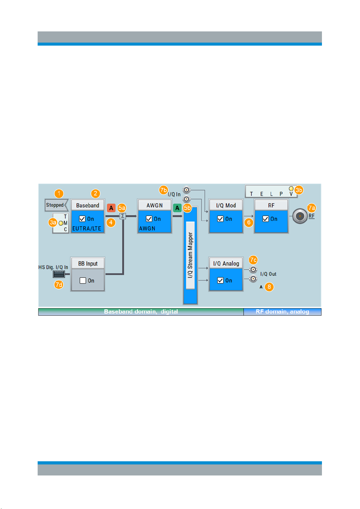
R&S®SMBV100B
Instrument Control
Understanding the Display Information
1 = Frequency display
2 = Status buttons
3 = Level display
The status buttons indicate key parameters that are set for the output signal. Most
of the status buttons are virtual keys you can use to open a corresponding menu
or dialog.
8.3.2 Block Diagram
The block diagram shows the current configuration and the signal flow in the generator with the aid of function blocks, connected by signal lines.
1 = Status indicator
2 = Functional block
3a / 3b = Control signal block
4 = Signal line (digital)
5a / 5b = Graphics indicator
6 = Signal line (analog)
7a / 7b / 7c / 7d = Connector icons (RF, analog, digital)
8 = Stream indicator
Starting from left up to the "I/Q Stream Mapper", you can see the functional
blocks provided in the baseband domain. After the stream mapper, the analog
section contains the digital to analog conversion and modulation to RF.
76Getting Started 1423.1049.02 ─ 05
Page 77

R&S®SMBV100B
Instrument Control
Understanding the Display Information
Legend Item Description
1 Status indicator Indicates whether the signal is running or waiting for a
trigger.
2 Functional block Represents a basic task in signal generation.
The push button provides access to any number of associated actions to accomplish the task.
The On/Off (checkbox) and the block label quickly activates the basic task.
3 Control signal block Indicates information on the control signals like signal
content, input or output and provides quick access to the
corresponding configuration dialog.
A dedicated control block is displayed for the baseband
block (3a) and RF block (3b).
4, 6 Signal lines (digital, ana-
log)
5 Graphics indicator Denotes that the signal is displayed graphically (5a/5b).
7 Connector icons Represent the interfaces for signal input and output.
8 Stream indicators Show the input streams at the I/Q stream mapper.
Show the currently configured signal flow.
●
Thick lines represent the digital I/Q streams, see (4)
in the figure above
●
Thin lines represent the analog signals (6)
●
RF signal connector output (7a); (icons vary depending on the frequency)
●
Analog I/Q signal connector input (7b)
●
Analog I/Q signal connector output (7c)
●
Digital I/Q signal connector input (7d)
●
Digital I/Q HS signal connector input and output (7b,
7c)
8.3.3 Taskbar
The "Taskbar" contains labeled softkeys and minimized views (thumbnails) of
active graphics and dialogs.
Initially, it shows the permanently assigned softkeys. The softkey with the sine
wave denotes that no signal is activated for graphical representation.
Figure 8-2: Taskbar in default state
77Getting Started 1423.1049.02 ─ 05
Page 78

R&S®SMBV100B
Instrument Control
Understanding the Display Information
Whenever you open a settings or graphics dialog, it is automatically assigned to
the "Taskbar". The softkeys shown in the following figure represent the variants.
Figure 8-3: Taskbar fully assigned
1 = System configuration
2 = Remote control connections
3 = Graphics
4 = Dialogs
5 = Diagram / more
1 SystemConfig Provides access to general system configurations
like setup, display, or remote.
2 Remote Shows the established remote connections when
the instrument is remotely controlled.
Tip: An indicator in the status bar shows the current
remote control status.
3 Graphics Shows that a signal is represented graphically.
4 Dialogs Shows a dialog as a thumbnail, the dialog name,
and the name of signal channel.
5 Diagram / more The diagram icon as shown in Figure 8-2 minimizes
all dialogs indicated on the screen. The block diagram is in the foreground.
The "More" softkey indicates that more dialogs are
open than can be displayed in the taskbar. Use this
softkey to open a selection list with the remaining
active dialogs, and the "Diagram" function.
8.3.4 Additional Display Characteristics
The following section provides a short insight on the indication of the screen in
general, and significant elements that you see under specific operating modes, in
dialogs or settings.
●
Appearance of active elements
– Active elements like On/Off switches, state buttons have a blue back-
ground.
– Selected elements are framed or highlighted orange.
– Inactive elements are gray.
78Getting Started 1423.1049.02 ─ 05
Page 79

R&S®SMBV100B
Instrument Control
Understanding the Display Information
●
On-Screen keypads
As additional means of interacting with the instrument without having to connect an external keyboard, either a numerical or alphanumerical on-screen
keypad appears when you activate an entry field (see Chapter 8.5, "Entering
Data", on page 82).
●
Info line
The "Info line" shows brief status information and error messages. It appears
when an event generates a message.
●
Key parameters indicated in tab labels
Most dialogs are divided into tabs with logically grouped parameters. The tab
label expresses the content and can also contain status indicators or the set
value of a key parameter.
1 = Status indicators
2 = Key parameter values
●
Scroll bar handle
An arrow icon that appears when you touch a scroll bar helps you to scroll in a
dialog or list.
●
Context-sensitive menus
Within the entire screen display, including single parameters, you can access
context-sensitive menus that provide some additional functions.
79Getting Started 1423.1049.02 ─ 05
Page 80

R&S®SMBV100B
Instrument Control
Accessing the Functionality
8.4 Accessing the Functionality
All functionalities are provided in dialog boxes as known from computer programs. You can control the instrument intuitively with the touchscreen. This section provides an overview of the accessing methods.
The instrument's functions and settings can be accessed by selecting one of the
following elements:
●
System and function keys on the front panel of the instrument
●
Taskbar/softkeys on the touchscreen
●
Context-sensitive menus for specific elements on the touchscreen, or with the
rotary knob (press and hold).
●
Elements on the status bar in the touchscreen
●
Displayed setting on the touchscreen, that means block diagram and all settings available in dialogs.
To open a dialog box
► Perform one of the following actions:
80Getting Started 1423.1049.02 ─ 05
Page 81

R&S®SMBV100B
Accessing the Functionality
● Tap the required block, and then the menu entry.
● Tap the minimized view (thumbnail) on the taskbar.
Some of the utility keys access a dedicated dialog, too.
To minimize a dialog box
► Tap the "Minimize" icon in the upper right corner.
To close a dialog box
To close a dialog box, you have the same controls as you know from computers
or devices with touchscreen.
► Perform one of the following actions:
● Tap the "Close" icon in the upper right corner.
● Press the [Esc] key on the front panel.
● Drag and drop a minimized dialog from the taskbar to the block diagram.
Instrument Control
To select an option in a dialog box
► Tap the required option.
To select an option in a list
If many options are available - for example, for the trigger mode - the options are
provided in a list. The current selection is shown on the list button.
1. Tap in the list.
2. To navigate through the list, try out the following:
● Using a mouse, scroll in the list, tap the required option.
● Use the rotary knob.
● Use [On/Off Toggle] key to select the succeeding option
● Use the front panel keys:
a) Press the [Left/Right] arrow keys to navigate to the list button.
b) Press the [Enter] key to open the list.
c) Press the [Up/Down] keys to navigate to the required option in the list.
d) Press the [Enter] key to select the marked option.
81Getting Started 1423.1049.02 ─ 05
Page 82

R&S®SMBV100B
Instrument Control
Entering Data
8.5 Entering Data
Some parameters have their own key on the front panel.
For data input in dialog boxes, the instrument provides on-screen keypads for
entering numeric and alphanumeric values. Thus, you can always set the parameters via the touchscreen, the front panel, or an external keyboard.
Correcting an entry
1. Using the arrow keys, move the cursor to the right of the entry you want to
delete.
2. Press the [Backspace] key.
3. Deletes the entry to the left of the cursor.
4. Enter your correction.
Completing the entry
► Press the [Enter] key or the rotary knob.
Aborting the entry
► Press the [Esc] key.
The dialog box closes without changing the settings.
8.5.1 Entering Numeric Parameters
To enter values with the on-screen keypad
For numeric settings, the instrument displays the numeric keypad. The units
specified correspond to the units of the parameter.
1. Enter the numeric value.
2. Tap the unit button to complete the entry.
The unit is added to the entry.
3. If the parameter does not require a unit, confirm the entered value by pressing
"Enter".
82Getting Started 1423.1049.02 ─ 05
Page 83

R&S®SMBV100B
Getting Information and Help
To enter values by using the front panel controls
1. Change the currently used parameter value by using the rotary knob or the
[Up/Down] keys.
2. If the parameter does not require a unit, confirm the entered value by pressing
the [Enter] key or any of the unit keys.
The instrument highlights the editing line to confirm the entry.
If you edit numeric data in tables, the entry field must be in edit mode: Press
[Enter], or the rotary knob to activate the edit mode.
Instrument Control
8.5.2 Entering Alphanumeric Parameters
If a field requires alphanumeric input, you can use the on-screen keyboard to
enter letters and (special) characters.
8.5.3 Undo and Redo Actions
Accessed via the context-sensitive menus, "Undo" allows you to restore one or
more actions on the instrument. Depending on the available memory, the "Undo"
steps can restore all actions.
"Redo" restores a previously undone action.
8.6 Getting Information and Help
In some dialog boxes, graphics are included to explain the way a setting works.
For further information, you can use the following sources:
●
Tooltips give the value range of the parameter.
●
The context help provides functional description on a setting.
●
The general help explains a dialog box, provides instructions, and general
information.
83Getting Started 1423.1049.02 ─ 05
Page 84

R&S®SMBV100B
Getting Information and Help
To display context help
► To access a help topic, perform one of the following:
a) Tap and hold the parameter for which you need information and tap "Help"
in the context menu.
b) Tap the parameter and press the [Help] key.
The "Help" dialog opens. You can browse the help for further information.
Instrument Control
Contents of the help dialog box
The help dialog box covers two main areas:
●
"Contents" - contains a table of help contents
●
"Topic" - contains a specific help topic
The help system also provides an "Index" and a "Find" area, and "Zoom" functions that are accessed via the corresponding buttons.
To open general help
► Press the yellow [Help] key on the front panel.
If a dialog box is opened, the help topic for the current tab is shown. Otherwise the "Contents" page appears.
84Getting Started 1423.1049.02 ─ 05
Page 85

R&S®SMBV100B
Navigating in the table of contents and in the help topics
1. To move through the displayed contents entries, tap on an entry and scroll or
use a connected mouse or the [Up/Down] keys.
Entries with a plus sign contain further entries.
2. To display a help topic, tap on the topic name or double click on the topic
name or press the [Enter] key.
3. To follow a cross-reference, tap on the link text.
4. To return to the previous page, select "Back".
This function scrolls back all steps you have performed before.
5. Use the "scroll bars" to shift the visible section of content shown.
6. To maximize the "Topics" area, tap the "Hide Contents Tree" button to hide the
contents tree.
Instrument Control
Remote Control
Using the index
1. Select the "Index" button.
2. Enter the first characters of the topic you are interested in.
The entries starting with these characters are displayed.
3. Tap on the index entry.
The corresponding help topic is displayed.
8.7 Remote Control
In addition to working with the R&S SMBV100B interactively, located directly at
the instrument, it is also possible to operate and control it from a remote PC.
The R&S SMBV100B supports various methods for remote control:
●
Connecting the instrument to a LAN (see Chapter 4.7, "Connecting to LAN",
on page 22)
●
Using the LXI browser interface in a LAN
●
Connecting a PC via the IEC-bus (IEEE 488) interface
●
Remote control via the USB interface
85Getting Started 1423.1049.02 ─ 05
Page 86

R&S®SMBV100B
Remote Operation over VNC
For remote control over LAN or USB, you can use the R&S VISA (Virtual
Instrument Software Architecture) library provided for download at the
Rohde & Schwarz website http://www.rohde-schwarz.com/rsvisa.
How to configure the remote control interfaces is described in the user manual,
chapter "Network and Remote Control Operation".
Instrument Control
8.8 Remote Operation over VNC
The VNC is an application which can be used to access and control the instrument from a remote computer through a LAN connection. While the instrument is
in operation, the instrument screen contents are displayed on the remote computer, and VNC provides access to all applications, files, and network resources
of the instrument. Thus, remote operation of the instrument is possible.
Instrument control from a remote computer
To access the basic utility functions of the R&S SMBV100B, perform a right
mouse click on the block diagram and select "Key Emulation".
A key panel to the right of the block diagram gives access to the utility functions provided by the front panel keys.
The VNC is an add-on program, included in operating system Linux/Unix, and
available as a free-of-charge download on the internet.
For more information, refer to the R&S SMBV100B user manual, chapter "How to
Set Up Remote Operation via VNC".
86Getting Started 1423.1049.02 ─ 05
Page 87

R&S®SMBV100B
Contacting Customer Support
9 Contacting Customer Support
Technical support – where and when you need it
For quick, expert help with any Rohde & Schwarz equipment, contact one of our
Customer Support Centers. A team of highly qualified engineers provides telephone support and works with you to find a solution to your query on any aspect
of the operation, programming or applications of Rohde & Schwarz equipment.
Up-to-date information and upgrades
To keep your instrument up-to-date and to be informed about new application
notes related to your instrument, please send an e-mail to the Customer Support
Center stating your instrument and your wish. We will make sure that you get the
right information.
Europe, Africa, Middle East
Phone +49 89 4129 12345
customersupport@rohde-schwarz.com
North America
Phone 1-888-TEST-RSA (1-888-837-8772)
customer.support@rsa.rohde-schwarz.com
Latin America
Phone +1-410-910-7988
customersupport.la@rohde-schwarz.com
Asia/Pacific
Phone +65 65 13 04 88
customersupport.asia@rohde-schwarz.com
China
Phone +86-800-810-8228 / +86-400-650-5896
customersupport.china@rohde-schwarz.com
87Getting Started 1423.1049.02 ─ 05
Page 88

R&S®SMBV100B
Contacting Customer Support
88Getting Started 1423.1049.02 ─ 05
Page 89

R&S®SMBV100B
Index
Index
A
Active elements ....................................... 78
Alphanumeric parameters ....................... 83
Application cards ..................................... 15
Application notes ..................................... 15
ARB ......................................................... 69
Arrow keys ...............................................36
B
Baseband
Input ....................................................69
Baseband generator ................................69
BB Input ...................................................69
Bench top, placing ...................................18
Block diagram
Display ................................................ 76
Brochures ................................................ 14
C
Carrying the instrument ........................... 17
Cfast card ................................................ 41
Checking the instrument ..........................17
Connecting
Keyboard ............................................ 23
LAN .....................................................22
Memory stick .......................................23
Mouse ................................................. 23
Power ..................................................22
To HS Dig I/Q ...................................... 26
To LO In/LO Out ..................................24
To Ref In/Ref Out ................................ 25
To RF .................................................. 24
USB devices ....................................... 23
Connector
AC power supply .................................42
Control signal ......................................40
Data .................................................... 40
DIFF I/Q .............................................. 39
Differential output ................................39
Digital IQ ............................................. 40
GPIB ................................................... 41
High-speed digital IQ .......................... 40
I .....................................................39, 40
I Bar .................................................... 39
IEC/IEEE .............................................41
Inst Trig ...............................................41
LAN .....................................................42
LF ........................................................40
LO In ................................................... 40
LO Out ................................................ 40
Mod Ext ...............................................41
Pulse Ext .............................................41
Pulse Video .........................................41
Q ................................................... 39, 40
Q Bar .................................................. 39
Ref In .................................................. 40
Ref Out ............................................... 40
RF ....................................................... 38
Sensor ................................................ 37
Signal Valid ......................................... 41
Single-ended output ............................39
USB .............................................. 37, 42
USB In ................................................ 42
User .................................................... 37
USER ..................................................39
Connectors .............................................. 38
Context-sensitive menu ...........................78
Custom Digital Modulation ...................... 69
D
Data entry ................................................82
Data sheets ............................................. 14
Dialog boxes ............................................80
Digital standard ....................................... 69
Display
Active elements .................................. 78
Block diagram ..................................... 76
Context-sensitive menu ...................... 78
Info line ............................................... 78
Information ..........................................75
On-screen keypad .............................. 78
Status bar ........................................... 75
Tab labels ............................................78
Taskbar ............................................... 77
Documentation overview ......................... 13
E
Emulating front panel keys ...................... 86
F
Firmware options
see Software options .......................... 69
89Getting Started 1423.1049.02 ─ 05
Page 90

R&S®SMBV100B
Index
Function keys
Details - see user manual ................... 34
Overview .............................................34
G
Getting started .........................................13
H
Head panel
see Status bar .....................................32
Header
see Status bar .....................................32
Help ................................................... 13, 84
Hotspot .................................................... 77
I
Info line ....................................................78
Input connector ......................37, 39, 40, 41
Instrument
Carrying .............................................. 17
Checking .............................................17
Lifting .................................................. 17
Operating site ..................................... 18
Unpacking ...........................................17
Instrument control ....................................73
Instrument help ........................................13
Instrument security procedures ............... 14
K
Key .................................................... 34, 36
★ (User) .............................................. 34
Access on a remote computer ............ 86
Backspace .................................... 34, 35
Down ...................................................36
Emulation ............................................86
Enter ............................................. 34, 35
Esc ................................................34, 35
Freq .................................................... 34
Help .................................................... 33
Home .................................................. 34
Left ......................................................36
Level ................................................... 34
Local ................................................... 33
Mod on/off ...........................................34
Next window ....................................... 36
On/Off Toggle ................................34, 36
On/Standby .........................................33
Preset ................................................. 33
Resize window ....................................36
RF on/off ............................................. 34
Right ................................................... 36
Save/Rcl ............................................. 33
Setup .................................................. 33
Up ....................................................... 36
Keyboard
On-screen ........................................... 82
Usage ................................................. 74
Keypad
On-screen ........................................... 82
Overview .............................................34
L
LAN
Connecting ..........................................22
Lifting the instrument ............................... 17
Loading
Trying out ............................................59
M
Manual interaction ................................... 74
Mass storage
Removable ..........................................41
Mounting, in a rack .................................. 19
Mouse
Usage ................................................. 74
N
Navigation keys ....................................... 36
Numeric data entry .................................. 82
Numeric parameters ................................82
O
On-screen keyboard ................................83
On-screen keypad ................................... 78
Open source acknowledgment (OSA) .....15
Operating site
Choosing .............................................18
Setting up the instrument ....................18
Operation
Manual ................................................ 74
Option
R&S SMBVB-K16 ............................... 39
Options
see User Manual .................................69
Output connector .............37, 38, 39, 40, 41
P
Parameters
Entering ........................................ 82, 83
Placing, on a bench top ...........................18
90Getting Started 1423.1049.02 ─ 05
Page 91

R&S®SMBV100B
Index
Power
Connecting the instrument ..................22
Power on
Key ......................................................33
Power supply
Connector ........................................... 42
Preparing for use .....................................17
R
Rack, mounting ....................................... 19
Release notes ......................................... 15
Remote access
see Remote operation from a computer
............................................................ 73
Remote control ........................................ 85
Remote operation ....................................86
Removable
Mass storage ...................................... 41
Non-Volatile Memory .......................... 41
Rotary knob ............................................. 35
S
Safety instructions ................................... 14
Saving
Trying out ............................................58
Serial number .......................................... 38
Service manual ........................................14
Softkey bar
see Taskbar ........................................ 77
Software options ......................................69
Standby
Key ......................................................33
Status bar
Display ................................................ 75
Switching
On or off ..............................................27
Utility keys
Details - see user manual ................... 33
Overview .............................................33
V
VNC
Using in a LAN ....................................86
W
White papers ........................................... 15
T
Tab labels ................................................ 78
Text entry ................................................. 82
Tooltips
Show ...................................................84
Touchscreen
Compared with mouse ........................74
Overview .............................................32
Usage ................................................. 74
U
Unpacking the instrument ........................17
User manual ............................................ 13
91Getting Started 1423.1049.02 ─ 05
 Loading...