

Page 1

R&S®SMA100B
RF Signal Generator
User Manual
(;ÜVR2)
1178.3834.02 ─ 03
User Manual
Page 2

This document describes the R&S®SMA100B, stock no. 1419.8888.02 and its options:
●
R&S®SMAB-B1H
●
R&S®SMAB-B29
●
R&S®SMAB-B32/-B34
●
R&S®SMAB-B80/-B85
●
R&S®SMAB-B81
●
R&S®SMAB-B86
●
R&S®SMAB-B92/-B93
●
R&S®SMAB-B103/-B106/-B112/-B120
●
R&S®SMAB-B710(N)/-B711(N)
●
R&S®SMAB-K22/-K23/-K24/-K27
●
R&S®SMAB-K31/-K33
●
R&S®SMAB-K703
●
R&S®SMAB-K704
●
R&S®SMAB-K720
●
R&S®SMAB-K722
This manual describes firmware version FW 4.15.080.xx and later of the R&S®SMA100B.
© 2017 Rohde & Schwarz GmbH & Co. KG
Mühldorfstr. 15, 81671 München, Germany
Phone: +49 89 41 29 - 0
Fax: +49 89 41 29 12 164
Email: info@rohde-schwarz.com
Internet: www.rohde-schwarz.com
Subject to change – Data without tolerance limits is not binding.
R&S® is a registered trademark of Rohde & Schwarz GmbH & Co. KG.
Trade names are trademarks of their owners.
Throughout this manual, products from Rohde & Schwarz are indicated without the ® symbol , e.g. R&S®SMA100B is indicated as
R&S SMAB. Linux® is abbreviated as Linux.
Page 3
Basic Safety Instructions
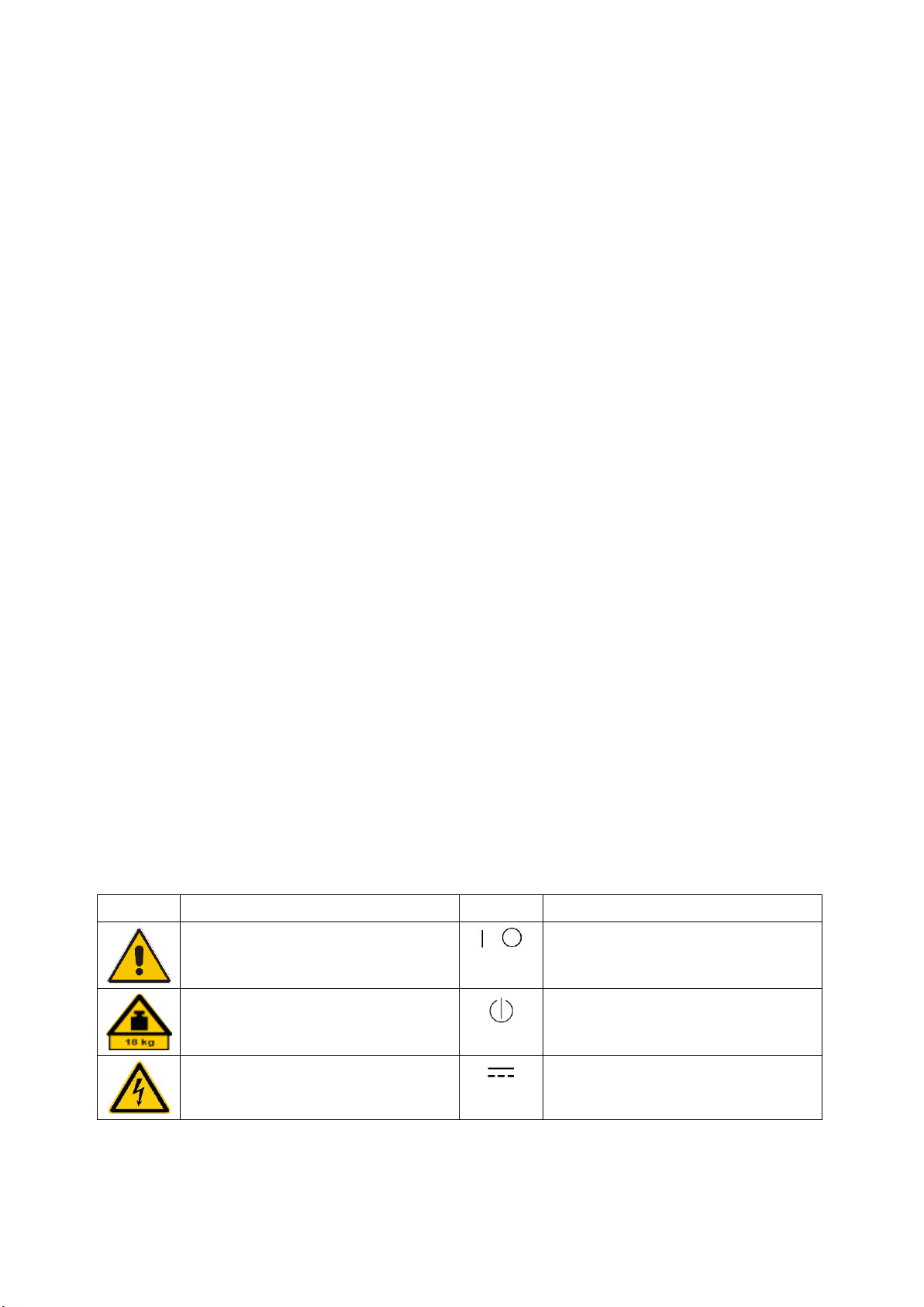
Symbol
Meaning
Symbol
Meaning
Notice, general danger location
Observe product documentation
ON/OFF Power
Caution when handling heavy equipment
Standby indication
Danger of electric shock
Direct current (DC)
Always read through and comply with the following safety instructions!
All plants and locations of the Rohde & Schwarz group of companies make every effort to keep the safety
standards of our products up to date and to offer our customers the highest possible degree of safety. Our
products and the auxiliary equipment they require are designed, built and tested in accordance with the
safety standards that apply in each case. Compliance with these standards is continuously monitored by
our quality assurance system. The product described here has been designed, built and tested in
accordance with the EC Certificate of Conformity and has left the manufacturer’s plant in a condition fully
complying with safety standards. To maintain this condition and to ensure safe operation, you must
observe all instructions and warnings provided in this manual. If you have any questions regarding these
safety instructions, the Rohde & Schwarz group of companies will be happy to answer them.
Furthermore, it is your responsibility to use the product in an appropriate manner. This product is designed
for use solely in industrial and laboratory environments or, if expressly permitted, also in the field and must
not be used in any way that may cause personal injury or property damage. You are responsible if the
product is used for any purpose other than its designated purpose or in disregard of the manufacturer's
instructions. The manufacturer shall assume no responsibility for such use of the product.
The product is used for its designated purpose if it is used in accordance with its product documentation
and within its performance limits (see data sheet, documentation, the following safety instructions). Using
the product requires technical skills and, in some cases, a basic knowledge of English. It is therefore
essential that only skilled and specialized staff or thoroughly trained personnel with the required skills be
allowed to use the product. If personal safety gear is required for using Rohde & Schwarz products, this
will be indicated at the appropriate place in the product documentation. Keep the basic safety instructions
and the product documentation in a safe place and pass them on to the subsequent users.
Observing the safety instructions will help prevent personal injury or damage of any kind caused by
dangerous situations. Therefore, carefully read through and adhere to the following safety instructions
before and when using the product. It is also absolutely essential to observe the additional safety
instructions on personal safety, for example, that appear in relevant parts of the product documentation. In
these safety instructions, the word "product" refers to all merchandise sold and distributed by the Rohde &
Schwarz group of companies, including instruments, systems and all accessories. For product-specific
information, see the data sheet and the product documentation.
Safety labels on products
The following safety labels are used on products to warn against risks and dangers.
1171.0000.42 - 09 Page 1
Page 4

Basic Safety Instructions
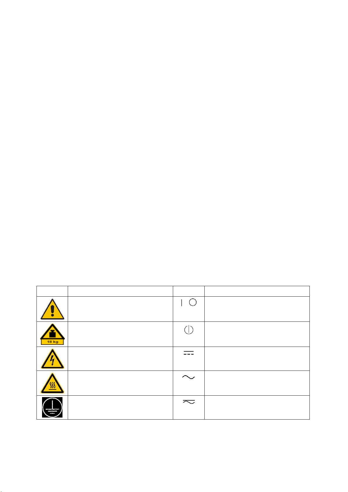
Symbol
Meaning
Symbol
Meaning
Caution ! Hot surface
Alternating current (AC)
Protective conductor terminal
To identify any terminal which is intended for
connection to an external conductor for
protection against electric shock in case of a
fault, or the terminal of a protective earth
Direct/alternating current (DC/AC)
Earth (Ground)
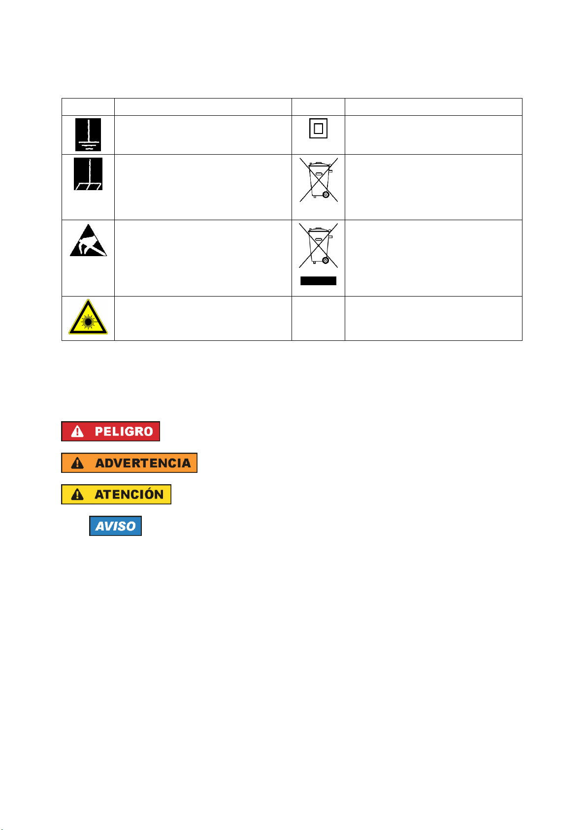
Class II Equipment
to identify equipment meeting the safety
requirements specified for Class II equipment
(device protected by double or reinforced
insulation)
Frame or chassis Ground terminal
EU labeling for batteries and accumulators
For additional information, see section "Waste
disposal/Environmental protection", item 1.
Be careful when handling electrostatic sensitive
devices
EU labeling for separate collection of electrical
and electronic devices
For additional information, see section "Waste
disposal/Environmental protection", item 2.
Warning! Laser radiation
For additional information, see section
"Operation", item 7.
Indicates a hazardous situation which, if not avoided, will result in death or
serious injury.
Indicates a hazardous situation which, if not avoided, could result in death or
serious injury.
Indicates a hazardous situation which, if not avoided, could result in minor or
moderate injury.
Indicates information considered important, but not hazard-related, e.g.
messages relating to property damage.
In the product documentation, the word ATTENTION is used synonymously.
Signal words and their meaning
The following signal words are used in the product documentation in order to warn the reader about risks
and dangers.
These signal words are in accordance with the standard definition for civil applications in the European
Economic Area. Definitions that deviate from the standard definition may also exist in other economic
areas or military applications. It is therefore essential to make sure that the signal words described here
are always used only in connection with the related product documentation and the related product. The
use of signal words in connection with unrelated products or documentation can result in misinterpretation
and in personal injury or material damage.
1171.0000.42 - 09 Page 2
Page 5

Basic Safety Instructions
Operating states and operating positions
The product may be operated only under the operating conditions and in the positions specified by the
manufacturer, without the product's ventilation being obstructed. If the manufacturer's specifications are
not observed, this can result in electric shock, fire and/or serious personal injury or death. Applicable local
or national safety regulations and rules for the prevention of accidents must be observed in all work
performed.
1. Unless otherwise specified, the following requirements apply to Rohde & Schwarz products:
predefined operating position is always with the housing floor facing down, IP protection 2X, use only
indoors, max. operating altitude 2000 m above sea level, max. transport altitude 4500 m above sea
level. A tolerance of ±10 % shall apply to the nominal voltage and ±5 % to the nominal frequency,
overvoltage category 2, pollution degree 2.
2. Do not place the product on surfaces, vehicles, cabinets or tables that for reasons of weight or stability
are unsuitable for this purpose. Always follow the manufacturer's installation instructions when
installing the product and fastening it to objects or structures (e.g. walls and shelves). An installation
that is not carried out as described in the product documentation could result in personal injury or
even death.
3. Do not place the product on heat-generating devices such as radiators or fan heaters. The ambient
temperature must not exceed the maximum temperature specified in the product documentation or in
the data sheet. Product overheating can cause electric shock, fire and/or serious personal injury or
even death.
Electrical safety
If the information on electrical safety is not observed either at all or to the extent necessary, electric shock,
fire and/or serious personal injury or death may occur.
1. Prior to switching on the product, always ensure that the nominal voltage setting on the product
matches the nominal voltage of the mains-supply network. If a different voltage is to be set, the power
fuse of the product may have to be changed accordingly.
2. In the case of products of safety class I with movable power cord and connector, operation is
permitted only on sockets with a protective conductor contact and protective conductor.
3. Intentionally breaking the protective conductor either in the feed line or in the product itself is not
permitted. Doing so can result in the danger of an electric shock from the product. If extension cords
or connector strips are implemented, they must be checked on a regular basis to ensure that they are
safe to use.
4. If there is no power switch for disconnecting the product from the mains, or if the power switch is not
suitable for this purpose, use the plug of the connecting cable to disconnect the product from the
mains. In such cases, always ensure that the power plug is easily reachable and accessible at all
times. For example, if the power plug is the disconnecting device, the length of the connecting cable
must not exceed 3 m. Functional or electronic switches are not suitable for providing disconnection
from the AC supply network. If products without power switches are integrated into racks or systems,
the disconnecting device must be provided at the system level.
5. Never use the product if the power cable is damaged. Check the power cables on a regular basis to
ensure that they are in proper operating condition. By taking appropriate safety measures and
carefully laying the power cable, ensure that the cable cannot be damaged and that no one can be
hurt by, for example, tripping over the cable or suffering an electric shock.
1171.0000.42 - 09 Page 3
Page 6

Basic Safety Instructions
6. The product may be operated only from TN/TT supply networks fuse-protected with max. 16 A (higher
fuse only after consulting with the Rohde & Schwarz group of companies).
7. Do not insert the plug into sockets that are dusty or dirty. Insert the plug firmly and all the way into the
socket provided for this purpose. Otherwise, sparks that result in fire and/or injuries may occur.
8. Do not overload any sockets, extension cords or connector strips; doing so can cause fire or electric
shocks.
9. For measurements in circuits with voltages V
> 30 V, suitable measures (e.g. appropriate
rms
measuring equipment, fuse protection, current limiting, electrical separation, insulation) should be
taken to avoid any hazards.
10. Ensure that the connections with information technology equipment, e.g. PCs or other industrial
computers, comply with the IEC 60950-1 / EN 60950-1 or IEC 61010-1 / EN 61010-1 standards that
apply in each case.
11. Unless expressly permitted, never remove the cover or any part of the housing while the product is in
operation. Doing so will expose circuits and components and can lead to injuries, fire or damage to the
product.
12. If a product is to be permanently installed, the connection between the protective conductor terminal
on site and the product's protective conductor must be made first before any other connection is
made. The product may be installed and connected only by a licensed electrician.
13. For permanently installed equipment without built-in fuses, circuit breakers or similar protective
devices, the supply circuit must be fuse-protected in such a way that anyone who has access to the
product, as well as the product itself, is adequately protected from injury or damage.
14. Use suitable overvoltage protection to ensure that no overvoltage (such as that caused by a bolt of
lightning) can reach the product. Otherwise, the person operating the product will be exposed to the
danger of an electric shock.
15. Any object that is not designed to be placed in the openings of the housing must not be used for this
purpose. Doing so can cause short circuits inside the product and/or electric shocks, fire or injuries.
16. Unless specified otherwise, products are not liquid-proof (see also section "Operating states and
operating positions", item 1). Therefore, the equipment must be protected against penetration by
liquids. If the necessary precautions are not taken, the user may suffer electric shock or the product
itself may be damaged, which can also lead to personal injury.
17. Never use the product under conditions in which condensation has formed or can form in or on the
product, e.g. if the product has been moved from a cold to a warm environment. Penetration by water
increases the risk of electric shock.
18. Prior to cleaning the product, disconnect it completely from the power supply (e.g. AC supply network
or battery). Use a soft, non-linting cloth to clean the product. Never use chemical cleaning agents such
as alcohol, acetone or diluents for cellulose lacquers.
Operation
1. Operating the products requires special training and intense concentration. Make sure that persons
who use the products are physically, mentally and emotionally fit enough to do so; otherwise, injuries
or material damage may occur. It is the responsibility of the employer/operator to select suitable
personnel for operating the products.
1171.0000.42 - 09 Page 4
Page 7

Basic Safety Instructions
2. Before you move or transport the product, read and observe the section titled "Transport".
3. As with all industrially manufactured goods, the use of substances that induce an allergic reaction
(allergens) such as nickel cannot be generally excluded. If you develop an allergic reaction (such as a
skin rash, frequent sneezing, red eyes or respiratory difficulties) when using a Rohde & Schwarz
product, consult a physician immediately to determine the cause and to prevent health problems or
stress.
4. Before you start processing the product mechanically and/or thermally, or before you take it apart, be
sure to read and pay special attention to the section titled "Waste disposal/Environmental protection",
item 1.
5. Depending on the function, certain products such as RF radio equipment can produce an elevated
level of electromagnetic radiation. Considering that unborn babies require increased protection,
pregnant women must be protected by appropriate measures. Persons with pacemakers may also be
exposed to risks from electromagnetic radiation. The employer/operator must evaluate workplaces
where there is a special risk of exposure to radiation and, if necessary, take measures to avert the
potential danger.
6. Should a fire occur, the product may release hazardous substances (gases, fluids, etc.) that can
cause health problems. Therefore, suitable measures must be taken, e.g. protective masks and
protective clothing must be worn.
7. Laser products are given warning labels that are standardized according to their laser class. Lasers
can cause biological harm due to the properties of their radiation and due to their extremely
concentrated electromagnetic power. If a laser product (e.g. a CD/DVD drive) is integrated into a
Rohde & Schwarz product, absolutely no other settings or functions may be used as described in the
product documentation. The objective is to prevent personal injury (e.g. due to laser beams).
8. EMC classes (in line with EN 55011/CISPR 11, and analogously with EN 55022/CISPR 22,
EN 55032/CISPR 32)
Class A equipment:
Equipment suitable for use in all environments except residential environments and environments
that are directly connected to a low-voltage supply network that supplies residential buildings
Note: Class A equipment is intended for use in an industrial environment. This equipment may
cause radio disturbances in residential environments, due to possible conducted as well as
radiated disturbances. In this case, the operator may be required to take appropriate measures to
eliminate these disturbances.
Class B equipment:
Equipment suitable for use in residential environments and environments that are directly
connected to a low-voltage supply network that supplies residential buildings
Repair and service
1. The product may be opened only by authorized, specially trained personnel. Before any work is
performed on the product or before the product is opened, it must be disconnected from the AC supply
network. Otherwise, personnel will be exposed to the risk of an electric shock.
1171.0000.42 - 09 Page 5
Page 8

Basic Safety Instructions
2. Adjustments, replacement of parts, maintenance and repair may be performed only by electrical
experts authorized by Rohde & Schwarz. Only original parts may be used for replacing parts relevant
to safety (e.g. power switches, power transformers, fuses). A safety test must always be performed
after parts relevant to safety have been replaced (visual inspection, protective conductor test,
insulation resistance measurement, leakage current measurement, functional test). This helps ensure
the continued safety of the product.
Batteries and rechargeable batteries/cells
If the information regarding batteries and rechargeable batteries/cells is not observed either at all or to the
extent necessary, product users may be exposed to the risk of explosions, fire and/or serious personal
injury, and, in some cases, death. Batteries and rechargeable batteries with alkaline electrolytes (e.g.
lithium cells) must be handled in accordance with the EN 62133 standard.
1. Cells must not be taken apart or crushed.
2. Cells or batteries must not be exposed to heat or fire. Storage in direct sunlight must be avoided.
Keep cells and batteries clean and dry. Clean soiled connectors using a dry, clean cloth.
3. Cells or batteries must not be short-circuited. Cells or batteries must not be stored in a box or in a
drawer where they can short-circuit each other, or where they can be short-circuited by other
conductive materials. Cells and batteries must not be removed from their original packaging until they
are ready to be used.
4. Cells and batteries must not be exposed to any mechanical shocks that are stronger than permitted.
5. If a cell develops a leak, the fluid must not be allowed to come into contact with the skin or eyes. If
contact occurs, wash the affected area with plenty of water and seek medical aid.
6. Improperly replacing or charging cells or batteries that contain alkaline electrolytes (e.g. lithium cells)
can cause explosions. Replace cells or batteries only with the matching Rohde & Schwarz type (see
parts list) in order to ensure the safety of the product.
7. Cells and batteries must be recycled and kept separate from residual waste. Rechargeable batteries
and normal batteries that contain lead, mercury or cadmium are hazardous waste. Observe the
national regulations regarding waste disposal and recycling.
8. Follow the transport stipulations of the carrier (IATA-DGR, IMDG-Code, ADR, RID) when returning
lithium batteries to Rohde & Schwarz subsidiaries.
Transport
1. The product may be very heavy. Therefore, the product must be handled with care. In some cases,
the user may require a suitable means of lifting or moving the product (e.g. with a lift-truck) to avoid
back or other physical injuries.
2. Handles on the products are designed exclusively to enable personnel to transport the product. It is
therefore not permissible to use handles to fasten the product to or on transport equipment such as
cranes, fork lifts, wagons, etc. The user is responsible for securely fastening the products to or on the
means of transport or lifting. Observe the safety regulations of the manufacturer of the means of
transport or lifting. Noncompliance can result in personal injury or material damage.
1171.0000.42 - 09 Page 6
Page 9

Instrucciones de seguridad elementales
3. If you use the product in a vehicle, it is the sole responsibility of the driver to drive the vehicle safely
and properly. The manufacturer assumes no responsibility for accidents or collisions. Never use the
product in a moving vehicle if doing so could distract the driver of the vehicle. Adequately secure the
product in the vehicle to prevent injuries or other damage in the event of an accident.
Waste disposal/Environmental protection
1. Specially marked equipment has a battery or accumulator that must not be disposed of with unsorted
municipal waste, but must be collected separately. It may only be disposed of at a suitable collection
point or via a Rohde & Schwarz customer service center.
2. Waste electrical and electronic equipment must not be disposed of with unsorted municipal waste, but
must be collected separately.
Rohde & Schwarz GmbH & Co. KG has developed a disposal concept and takes full responsibility for
take-back obligations and disposal obligations for manufacturers within the EU. Contact your
Rohde & Schwarz customer service center for environmentally responsible disposal of the product.
3. If products or their components are mechanically and/or thermally processed in a manner that goes
beyond their intended use, hazardous substances (heavy-metal dust such as lead, beryllium, nickel)
may be released. For this reason, the product may only be disassembled by specially trained
personnel. Improper disassembly may be hazardous to your health. National waste disposal
regulations must be observed.
4. If handling the product releases hazardous substances or fuels that must be disposed of in a special
way, e.g. coolants or engine oils that must be replenished regularly, the safety instructions of the
manufacturer of the hazardous substances or fuels and the applicable regional waste disposal
regulations must be observed. Also observe the relevant safety instructions in the product
documentation. The improper disposal of hazardous substances or fuels can cause health problems
and lead to environmental damage.
For additional information about environmental protection, visit the Rohde & Schwarz website.
Instrucciones de seguridad elementales
¡Es imprescindible leer y cumplir las siguientes instrucciones e informaciones de seguridad!
El principio del grupo de empresas Rohde & Schwarz consiste en tener nuestros productos siempre al día
con los estándares de seguridad y de ofrecer a nuestros clientes el máximo grado de seguridad. Nuestros
productos y todos los equipos adicionales son siempre fabricados y examinados según las normas de
seguridad vigentes. Nuestro sistema de garantía de calidad controla constantemente que sean cumplidas
estas normas. El presente producto ha sido fabricado y examinado según el certificado de conformidad
de la UE y ha salido de nuestra planta en estado impecable según los estándares técnicos de seguridad.
Para poder preservar este estado y garantizar un funcionamiento libre de peligros, el usuario deberá
atenerse a todas las indicaciones, informaciones de seguridad y notas de alerta. El grupo de empresas
Rohde & Schwarz está siempre a su disposición en caso de que tengan preguntas referentes a estas
informaciones de seguridad.
1171.0000.42 - 09 Page 7
Page 10
Instrucciones de seguridad elementales
Símbolo
Significado
Símbolo
Significado
Aviso: punto de peligro general
Observar la documentación del producto
Tensión de alimentación de PUESTA EN
MARCHA / PARADA
Atención en el manejo de dispositivos de peso
elevado
Indicación de estado de espera (standby)
Peligro de choque eléctrico
Corriente continua (DC)
Advertencia: superficie caliente
Corriente alterna (AC)
Conexión a conductor de protección
Corriente continua / Corriente alterna (DC/AC)
Además queda en la responsabilidad del usuario utilizar el producto en la forma debida. Este producto
está destinado exclusivamente al uso en la industria y el laboratorio o, si ha sido expresamente
autorizado, para aplicaciones de campo y de ninguna manera deberá ser utilizado de modo que alguna
persona/cosa pueda sufrir daño. El uso del producto fuera de sus fines definidos o sin tener en cuenta las
instrucciones del fabricante queda en la responsabilidad del usuario. El fabricante no se hace en ninguna
forma responsable de consecuencias a causa del mal uso del producto.
Se parte del uso correcto del producto para los fines definidos si el producto es utilizado conforme a las
indicaciones de la correspondiente documentación del producto y dentro del margen de rendimiento
definido (ver hoja de datos, documentación, informaciones de seguridad que siguen). El uso del producto
hace necesarios conocimientos técnicos y ciertos conocimientos del idioma inglés. Por eso se debe tener
en cuenta que el producto solo pueda ser operado por personal especializado o personas instruidas en
profundidad con las capacidades correspondientes. Si fuera necesaria indumentaria de seguridad para el
uso de productos de Rohde & Schwarz, encontraría la información debida en la documentación del
producto en el capítulo correspondiente. Guarde bien las informaciones de seguridad elementales, así
como la documentación del producto, y entréguelas a usuarios posteriores.
Tener en cuenta las informaciones de seguridad sirve para evitar en lo posible lesiones o daños por
peligros de toda clase. Por eso es imprescindible leer detalladamente y comprender por completo las
siguientes informaciones de seguridad antes de usar el producto, y respetarlas durante el uso del
producto. Deberán tenerse en cuenta todas las demás informaciones de seguridad, como p. ej. las
referentes a la protección de personas, que encontrarán en el capítulo correspondiente de la
documentación del producto y que también son de obligado cumplimiento. En las presentes
informaciones de seguridad se recogen todos los objetos que distribuye el grupo de empresas
Rohde & Schwarz bajo la denominación de "producto", entre ellos también aparatos, instalaciones así
como toda clase de accesorios. Los datos específicos del producto figuran en la hoja de datos y en la
documentación del producto.
Señalización de seguridad de los productos
Las siguientes señales de seguridad se utilizan en los productos para advertir sobre riesgos y peligros.
1171.0000.42 - 09 Page 8
Page 11
Instrucciones de seguridad elementales
Símbolo
Significado
Símbolo
Significado
Conexión a tierra
El aparato está protegido en su totalidad por un
aislamiento doble (reforzado)
Conexión a masa
Distintivo de la UE para baterías y
acumuladores
Más información en la sección
"Eliminación/protección del medio ambiente",
punto 1.
Aviso: Cuidado en el manejo de dispositivos
sensibles a la electrostática (ESD)
Distintivo de la UE para la eliminación por
separado de dispositivos eléctricos y
electrónicos
Más información en la sección
"Eliminación/protección del medio ambiente",
punto 2.
Advertencia: rayo láser
Más información en la sección
"Funcionamiento", punto 7.
Indica una situación de peligro que, si no se evita, causa lesiones
graves o incluso la muerte.
Indica una situación de peligro que, si no se evita, puede causar
lesiones graves o incluso la muerte.
Indica una situación de peligro que, si no se evita, puede causar
lesiones leves o moderadas.
Indica información que se considera importante, pero no en relación
con situaciones de peligro; p. ej., avisos sobre posibles daños
materiales.
En la documentación del producto se emplea de forma sinónima el
término CUIDADO.
Palabras de señal y su significado
En la documentación del producto se utilizan las siguientes palabras de señal con el fin de advertir contra
riesgos y peligros.
Las palabras de señal corresponden a la definición habitual para aplicaciones civiles en el área
económica europea. Pueden existir definiciones diferentes a esta definición en otras áreas económicas o
en aplicaciones militares. Por eso se deberá tener en cuenta que las palabras de señal aquí descritas
sean utilizadas siempre solamente en combinación con la correspondiente documentación del producto y
solamente en combinación con el producto correspondiente. La utilización de las palabras de señal en
combinación con productos o documentaciones que no les correspondan puede llevar a interpretaciones
equivocadas y tener por consecuencia daños en personas u objetos.
1171.0000.42 - 09 Page 9
Page 12

Instrucciones de seguridad elementales
Estados operativos y posiciones de funcionamiento
El producto solamente debe ser utilizado según lo indicado por el fabricante respecto a los estados
operativos y posiciones de funcionamiento sin que se obstruya la ventilación. Si no se siguen las
indicaciones del fabricante, pueden producirse choques eléctricos, incendios y/o lesiones graves con
posible consecuencia de muerte. En todos los trabajos deberán ser tenidas en cuenta las normas
nacionales y locales de seguridad del trabajo y de prevención de accidentes.
1. Si no se convino de otra manera, es para los productos Rohde & Schwarz válido lo que sigue:
como posición de funcionamiento se define por principio la posición con el suelo de la caja para
abajo, modo de protección IP 2X, uso solamente en estancias interiores, utilización hasta 2000 m
sobre el nivel del mar, transporte hasta 4500 m sobre el nivel del mar. Se aplicará una tolerancia de
±10 % sobre el voltaje nominal y de ±5 % sobre la frecuencia nominal. Categoría de sobrecarga
eléctrica 2, índice de suciedad 2.
2. No sitúe el producto encima de superficies, vehículos, estantes o mesas, que por sus características
de peso o de estabilidad no sean aptos para él. Siga siempre las instrucciones de instalación del
fabricante cuando instale y asegure el producto en objetos o estructuras (p. ej. paredes y estantes). Si
se realiza la instalación de modo distinto al indicado en la documentación del producto, se pueden
causar lesiones o, en determinadas circunstancias, incluso la muerte.
3. No ponga el producto sobre aparatos que generen calor (p. ej. radiadores o calefactores). La
temperatura ambiente no debe superar la temperatura máxima especificada en la documentación del
producto o en la hoja de datos. En caso de sobrecalentamiento del producto, pueden producirse
choques eléctricos, incendios y/o lesiones graves con posible consecuencia de muerte.
Seguridad eléctrica
Si no se siguen (o se siguen de modo insuficiente) las indicaciones del fabricante en cuanto a seguridad
eléctrica, pueden producirse choques eléctricos, incendios y/o lesiones graves con posible consecuencia
de muerte.
1. Antes de la puesta en marcha del producto se deberá comprobar siempre que la tensión
preseleccionada en el producto coincida con la de la red de alimentación eléctrica. Si es necesario
modificar el ajuste de tensión, también se deberán cambiar en caso dado los fusibles
correspondientes del producto.
2. Los productos de la clase de protección I con alimentación móvil y enchufe individual solamente
podrán enchufarse a tomas de corriente con contacto de seguridad y con conductor de protección
conectado.
3. Queda prohibida la interrupción intencionada del conductor de protección, tanto en la toma de
corriente como en el mismo producto. La interrupción puede tener como consecuencia el riesgo de
que el producto sea fuente de choques eléctricos. Si se utilizan cables alargadores o regletas de
enchufe, deberá garantizarse la realización de un examen regular de los mismos en cuanto a su
estado técnico de seguridad.
4. Si el producto no está equipado con un interruptor para desconectarlo de la red, o bien si el
interruptor existente no resulta apropiado para la desconexión de la red, el enchufe del cable de
conexión se deberá considerar como un dispositivo de desconexión.
El dispositivo de desconexión se debe poder alcanzar fácilmente y debe estar siempre bien accesible.
Si, p. ej., el enchufe de conexión a la red es el dispositivo de desconexión, la longitud del cable de
conexión no debe superar 3 m).
Los interruptores selectores o electrónicos no son aptos para el corte de la red eléctrica. Si se
1171.0000.42 - 09 Page 10
Page 13

Instrucciones de seguridad elementales
integran productos sin interruptor en bastidores o instalaciones, se deberá colocar el interruptor en el
nivel de la instalación.
5. No utilice nunca el producto si está dañado el cable de conexión a red. Compruebe regularmente el
correcto estado de los cables de conexión a red. Asegúrese, mediante las medidas de protección y
de instalación adecuadas, de que el cable de conexión a red no pueda ser dañado o de que nadie
pueda ser dañado por él, p. ej. al tropezar o por un choque eléctrico.
6. Solamente está permitido el funcionamiento en redes de alimentación TN/TT aseguradas con fusibles
de 16 A como máximo (utilización de fusibles de mayor amperaje solo previa consulta con el grupo de
empresas Rohde & Schwarz).
7. Nunca conecte el enchufe en tomas de corriente sucias o llenas de polvo. Introduzca el enchufe por
completo y fuertemente en la toma de corriente. La no observación de estas medidas puede provocar
chispas, fuego y/o lesiones.
8. No sobrecargue las tomas de corriente, los cables alargadores o las regletas de enchufe ya que esto
podría causar fuego o choques eléctricos.
9. En las mediciones en circuitos de corriente con una tensión U
> 30 V se deberán tomar las medidas
eff
apropiadas para impedir cualquier peligro (p. ej. medios de medición adecuados, seguros, limitación
de tensión, corte protector, aislamiento etc.).
10. Para la conexión con dispositivos informáticos como un PC o un ordenador industrial, debe
comprobarse que éstos cumplan los estándares IEC60950-1/EN60950-1 o IEC61010-1/EN 61010-1
válidos en cada caso.
11. A menos que esté permitido expresamente, no retire nunca la tapa ni componentes de la carcasa
mientras el producto esté en servicio. Esto pone a descubierto los cables y componentes eléctricos y
puede causar lesiones, fuego o daños en el producto.
12. Si un producto se instala en un lugar fijo, se deberá primero conectar el conductor de protección fijo
con el conductor de protección del producto antes de hacer cualquier otra conexión. La instalación y
la conexión deberán ser efectuadas por un electricista especializado.
13. En el caso de dispositivos fijos que no estén provistos de fusibles, interruptor automático ni otros
mecanismos de seguridad similares, el circuito de alimentación debe estar protegido de modo que
todas las personas que puedan acceder al producto, así como el producto mismo, estén a salvo de
posibles daños.
14. Todo producto debe estar protegido contra sobretensión (debida p. ej. a una caída del rayo) mediante
los correspondientes sistemas de protección. Si no, el personal que lo utilice quedará expuesto al
peligro de choque eléctrico.
15. No debe introducirse en los orificios de la caja del aparato ningún objeto que no esté destinado a ello.
Esto puede producir cortocircuitos en el producto y/o puede causar choques eléctricos, fuego o
lesiones.
16. Salvo indicación contraria, los productos no están impermeabilizados (ver también el capítulo
"Estados operativos y posiciones de funcionamiento", punto 1). Por eso es necesario tomar las
medidas necesarias para evitar la entrada de líquidos. En caso contrario, existe peligro de choque
eléctrico para el usuario o de daños en el producto, que también pueden redundar en peligro para las
personas.
1171.0000.42 - 09 Page 11
Page 14

Instrucciones de seguridad elementales
17. No utilice el producto en condiciones en las que pueda producirse o ya se hayan producido
condensaciones sobre el producto o en el interior de éste, como p. ej. al desplazarlo de un lugar frío a
otro caliente. La entrada de agua aumenta el riesgo de choque eléctrico.
18. Antes de la limpieza, desconecte por completo el producto de la alimentación de tensión (p. ej. red de
alimentación o batería). Realice la limpieza de los aparatos con un paño suave, que no se deshilache.
No utilice bajo ningún concepto productos de limpieza químicos como alcohol, acetona o diluyentes
para lacas nitrocelulósicas.
Funcionamiento
1. El uso del producto requiere instrucciones especiales y una alta concentración durante el manejo.
Debe asegurarse que las personas que manejen el producto estén a la altura de los requerimientos
necesarios en cuanto a aptitudes físicas, psíquicas y emocionales, ya que de otra manera no se
pueden excluir lesiones o daños de objetos. El empresario u operador es responsable de seleccionar
el personal usuario apto para el manejo del producto.
2. Antes de desplazar o transportar el producto, lea y tenga en cuenta el capítulo "Transporte".
3. Como con todo producto de fabricación industrial no puede quedar excluida en general la posibilidad
de que se produzcan alergias provocadas por algunos materiales empleados ―los llamados
alérgenos (p. ej. el níquel)―. Si durante el manejo de productos Rohde & Schwarz se producen
reacciones alérgicas, como p. ej. irritaciones cutáneas, estornudos continuos, enrojecimiento de la
conjuntiva o dificultades respiratorias, debe avisarse inmediatamente a un médico para investigar las
causas y evitar cualquier molestia o daño a la salud.
4. Antes de la manipulación mecánica y/o térmica o el desmontaje del producto, debe tenerse en cuenta
imprescindiblemente el capítulo "Eliminación/protección del medio ambiente", punto 1.
5. Ciertos productos, como p. ej. las instalaciones de radiocomunicación RF, pueden a causa de su
función natural, emitir una radiación electromagnética aumentada. Deben tomarse todas las medidas
necesarias para la protección de las mujeres embarazadas. También las personas con marcapasos
pueden correr peligro a causa de la radiación electromagnética. El empresario/operador tiene la
obligación de evaluar y señalizar las áreas de trabajo en las que exista un riesgo elevado de
exposición a radiaciones.
6. Tenga en cuenta que en caso de incendio pueden desprenderse del producto sustancias tóxicas
(gases, líquidos etc.) que pueden generar daños a la salud. Por eso, en caso de incendio deben
usarse medidas adecuadas, como p. ej. máscaras antigás e indumentaria de protección.
7. Los productos con láser están provistos de indicaciones de advertencia normalizadas en función de la
clase de láser del que se trate. Los rayos láser pueden provocar daños de tipo biológico a causa de
las propiedades de su radiación y debido a su concentración extrema de potencia electromagnética.
En caso de que un producto Rohde & Schwarz contenga un producto láser (p. ej. un lector de
CD/DVD), no debe usarse ninguna otra configuración o función aparte de las descritas en la
documentación del producto, a fin de evitar lesiones (p. ej. debidas a irradiación láser).
8. Clases de compatibilidad electromagnética (conforme a EN 55011 / CISPR 11; y en analogía con EN
55022 / CISPR 22, EN 55032 / CISPR 32)
Aparato de clase A:
Aparato adecuado para su uso en todos los entornos excepto en los residenciales y en aquellos
conectados directamente a una red de distribución de baja tensión que suministra corriente a
edificios residenciales.
Nota: Los aparatos de clase A están destinados al uso en entornos industriales. Estos aparatos
1171.0000.42 - 09 Page 12
Page 15

Instrucciones de seguridad elementales
pueden causar perturbaciones radioeléctricas en entornos residenciales debido a posibles
perturbaciones guiadas o radiadas. En este caso, se le podrá solicitar al operador que tome las
medidas adecuadas para eliminar estas perturbaciones.
Aparato de clase B:
Aparato adecuado para su uso en entornos residenciales, así como en aquellos conectados
directamente a una red de distribución de baja tensión que suministra corriente a edificios
residenciales.
Reparación y mantenimiento
1. El producto solamente debe ser abierto por personal especializado con autorización para ello. Antes
de manipular el producto o abrirlo, es obligatorio desconectarlo de la tensión de alimentación, para
evitar toda posibilidad de choque eléctrico.
2. El ajuste, el cambio de partes, el mantenimiento y la reparación deberán ser efectuadas solamente
por electricistas autorizados por Rohde & Schwarz. Si se reponen partes con importancia para los
aspectos de seguridad (p. ej. el enchufe, los transformadores o los fusibles), solamente podrán ser
sustituidos por partes originales. Después de cada cambio de partes relevantes para la seguridad
deberá realizarse un control de seguridad (control a primera vista, control del conductor de
protección, medición de resistencia de aislamiento, medición de la corriente de fuga, control de
funcionamiento). Con esto queda garantizada la seguridad del producto.
Baterías y acumuladores o celdas
Si no se siguen (o se siguen de modo insuficiente) las indicaciones en cuanto a las baterías y
acumuladores o celdas, pueden producirse explosiones, incendios y/o lesiones graves con posible
consecuencia de muerte. El manejo de baterías y acumuladores con electrolitos alcalinos (p. ej. celdas de
litio) debe seguir el estándar EN 62133.
1. No deben desmontarse, abrirse ni triturarse las celdas.
2. Las celdas o baterías no deben someterse a calor ni fuego. Debe evitarse el almacenamiento a la luz
directa del sol. Las celdas y baterías deben mantenerse limpias y secas. Limpiar las conexiones
sucias con un paño seco y limpio.
3. Las celdas o baterías no deben cortocircuitarse. Es peligroso almacenar las celdas o baterías en
estuches o cajones en cuyo interior puedan cortocircuitarse por contacto recíproco o por contacto con
otros materiales conductores. No deben extraerse las celdas o baterías de sus embalajes originales
hasta el momento en que vayan a utilizarse.
4. Las celdas o baterías no deben someterse a impactos mecánicos fuertes indebidos.
5. En caso de falta de estanqueidad de una celda, el líquido vertido no debe entrar en contacto con la
piel ni los ojos. Si se produce contacto, lavar con agua abundante la zona afectada y avisar a un
médico.
6. En caso de cambio o recarga inadecuados, las celdas o baterías que contienen electrolitos alcalinos
(p. ej. las celdas de litio) pueden explotar. Para garantizar la seguridad del producto, las celdas o
baterías solo deben ser sustituidas por el tipo Rohde & Schwarz correspondiente (ver lista de
recambios).
7. Las baterías y celdas deben reciclarse y no deben tirarse a la basura doméstica. Las baterías o
acumuladores que contienen plomo, mercurio o cadmio deben tratarse como residuos especiales.
Respete en esta relación las normas nacionales de eliminación y reciclaje.
1171.0000.42 - 09 Page 13
Page 16

Instrucciones de seguridad elementales
8. En caso de devolver baterías de litio a las filiales de Rohde & Schwarz, debe cumplirse las
normativas sobre los modos de transporte (IATA-DGR, código IMDG, ADR, RID).
Transporte
1. El producto puede tener un peso elevado. Por eso es necesario desplazarlo o transportarlo con
precaución y, si es necesario, usando un sistema de elevación adecuado (p. ej. una carretilla
elevadora), a fin de evitar lesiones en la espalda u otros daños personales.
2. Las asas instaladas en los productos sirven solamente de ayuda para el transporte del producto por
personas. Por eso no está permitido utilizar las asas para la sujeción en o sobre medios de transporte
como p. ej. grúas, carretillas elevadoras de horquilla, carros etc. Es responsabilidad suya fijar los
productos de manera segura a los medios de transporte o elevación. Para evitar daños personales o
daños en el producto, siga las instrucciones de seguridad del fabricante del medio de transporte o
elevación utilizado.
3. Si se utiliza el producto dentro de un vehículo, recae de manera exclusiva en el conductor la
responsabilidad de conducir el vehículo de manera segura y adecuada. El fabricante no asumirá
ninguna responsabilidad por accidentes o colisiones. No utilice nunca el producto dentro de un
vehículo en movimiento si esto pudiera distraer al conductor. Asegure el producto dentro del vehículo
debidamente para evitar, en caso de un accidente, lesiones u otra clase de daños.
Eliminación/protección del medio ambiente
1. Los dispositivos marcados contienen una batería o un acumulador que no se debe desechar con los
residuos domésticos sin clasificar, sino que debe ser recogido por separado. La eliminación se debe
efectuar exclusivamente a través de un punto de recogida apropiado o del servicio de atención al
cliente de Rohde & Schwarz.
2. Los dispositivos eléctricos usados no se deben desechar con los residuos domésticos sin clasificar,
sino que deben ser recogidos por separado.
Rohde & Schwarz GmbH & Co.KG ha elaborado un concepto de eliminación de residuos y asume
plenamente los deberes de recogida y eliminación para los fabricantes dentro de la UE. Para
desechar el producto de manera respetuosa con el medio ambiente, diríjase a su servicio de atención
al cliente de Rohde & Schwarz.
3. Si se trabaja de manera mecánica y/o térmica cualquier producto o componente más allá del
funcionamiento previsto, pueden liberarse sustancias peligrosas (polvos con contenido de metales
pesados como p. ej. plomo, berilio o níquel). Por eso el producto solo debe ser desmontado por
personal especializado con formación adecuada. Un desmontaje inadecuado puede ocasionar daños
para la salud. Se deben tener en cuenta las directivas nacionales referentes a la eliminación de
residuos.
4. En caso de que durante el trato del producto se formen sustancias peligrosas o combustibles que
deban tratarse como residuos especiales (p. ej. refrigerantes o aceites de motor con intervalos de
cambio definidos), deben tenerse en cuenta las indicaciones de seguridad del fabricante de dichas
sustancias y las normas regionales de eliminación de residuos. Tenga en cuenta también en caso
necesario las indicaciones de seguridad especiales contenidas en la documentación del producto. La
eliminación incorrecta de sustancias peligrosas o combustibles puede causar daños a la salud o
daños al medio ambiente.
Se puede encontrar más información sobre la protección del medio ambiente en la página web de
Rohde & Schwarz.
1171.0000.42 - 09 Page 14
Page 17

Customer Support
Technical support – where and when you need it
For quick, expert help with any Rohde & Schwarz equipment, contact one of our Customer Support
Centers. A team of highly qualified engineers provides telephone support and will work with you to find a
solution to your query on any aspect of the operation, programming or applications of Rohde & Schwarz
equipment.
Up-to-date information and upgrades
To keep your instrument up-to-date and to be informed about new application notes related to your
instrument, please send an e-mail to the Customer Support Center stating your instrument and your wish.
We will take care that you will get the right information.
Europe, Africa, Middle East
North America
Latin America
Asia/Pacific
China
Phone +49 89 4129 12345
customersupport@rohde-schwarz.com
Phone 1-888-TEST-RSA (1-888-837-8772)
customer.support@rsa.rohde-schwarz.com
Phone +1-410-910-7988
customersupport.la@rohde-schwarz.com
Phone +65 65 13 04 88
customersupport.asia@rohde-schwarz.com
Phone +86-800-810-8228 /
+86-400-650-5896
customersupport.china@rohde-schwarz.com
1171.0200.22-06.00
Page 18

R&S®SMA100B
1 Preface.................................................................................................. 15
1.1 Key Features................................................................................................................15
1.2 For Your Safety........................................................................................................... 15
1.3 About this Manual....................................................................................................... 16
1.4 Documentation Overview........................................................................................... 17
1.4.1 Getting Started Manual................................................................................................. 17
1.4.2 User Manuals and Help.................................................................................................17
1.4.3 Service Manual............................................................................................................. 17
1.4.4 Instrument Security Procedures....................................................................................18
1.4.5 Basic Safety Instructions...............................................................................................18
1.4.6 Data Sheets and Brochures.......................................................................................... 18
Contents
Contents
1.4.7 Release Notes and Open Source Acknowledgment (OSA).......................................... 18
1.4.8 Application Notes, Application Cards, White Papers, etc..............................................18
2 Getting Started..................................................................................... 19
2.1 Preparing for Use........................................................................................................ 19
2.1.1 Putting into Operation................................................................................................... 19
2.1.1.1 EMI Suppression...........................................................................................................20
2.1.1.2 Unpacking and Checking the Instrument...................................................................... 20
2.1.1.3 Accessory List............................................................................................................... 21
2.1.1.4 Placing or Mounting the Instrument.............................................................................. 21
2.1.1.5 Connecting AC Power...................................................................................................22
2.1.1.6 Turning the Instrument On and Off............................................................................... 23
2.1.1.7 Functional Check.......................................................................................................... 24
2.1.1.8 Checking the Supplied Options and Licenses...............................................................25
2.1.2 Connecting USB Devices..............................................................................................25
2.1.3 Setting Up a Network (LAN) Connection.......................................................................26
2.1.3.1 Connecting the Instrument to the Network....................................................................26
2.1.3.2 Using Computer Names (Hostnames).......................................................................... 27
2.1.3.3 Assigning the IP Address.............................................................................................. 28
2.1.4 Configuring the Initial Instrument Settings.................................................................... 29
2.1.4.1 Setting the Date and Time............................................................................................ 30
3User Manual 1178.3834.02 ─ 03
Page 19

R&S®SMA100B
2.1.4.2 Setting the Keyboard Language....................................................................................31
2.1.4.3 Setting the Screen Saver.............................................................................................. 31
2.2 Instrument Tour...........................................................................................................32
2.2.1 Front Panel Tour........................................................................................................... 32
2.2.1.1 Touchscreen................................................................................................................. 34
2.2.1.2 Utility Keys.................................................................................................................... 34
2.2.1.3 ON/STANDBY...............................................................................................................35
2.2.1.4 Function Keys............................................................................................................... 35
2.2.1.5 Keypad.......................................................................................................................... 35
2.2.1.6 Navigation Controls.......................................................................................................36
Contents
Rotary Knob.................................................................................................................. 36
Editing Keys.................................................................................................................. 36
Navigation Keys............................................................................................................ 37
2.2.1.7 Display Keys................................................................................................................. 37
2.2.1.8 USB Connector............................................................................................................. 37
2.2.1.9 SD card slot...................................................................................................................38
2.2.1.10 SENSOR....................................................................................................................... 38
2.2.1.11 RF 50 Ω.........................................................................................................................38
2.2.1.12 Pulse Signal Connectors...............................................................................................39
2.2.1.13 LF Modulation Connectors............................................................................................ 39
2.2.1.14 Clock Synthesizer Connectors...................................................................................... 40
2.2.2 Rear Panel Tour............................................................................................................40
2.2.2.1 Connectors....................................................................................................................41
2.3 Trying Out the Instrument.......................................................................................... 43
2.3.1 Generating an Unmodulated Carrier............................................................................. 44
2.3.2 Generating an RF Frequency Sweep Signal.................................................................46
2.3.3 Saving and Recalling Settings...................................................................................... 48
2.4 Instrument Control......................................................................................................51
2.4.1 Possible Ways to Operate the Instrument.....................................................................52
2.4.2 Means of Manual Interaction.........................................................................................52
2.4.3 Understanding the Display Information......................................................................... 53
2.4.3.1 Status Bar..................................................................................................................... 53
2.4.3.2 Tile Diagram..................................................................................................................53
4User Manual 1178.3834.02 ─ 03
Page 20

R&S®SMA100B
2.4.3.3 Taskbar......................................................................................................................... 54
2.4.3.4 Additional Display Characteristics.................................................................................55
2.4.4 Accessing the Functionality...........................................................................................56
2.4.5 Entering Data................................................................................................................ 57
2.4.5.1 Entering Numeric Parameters.......................................................................................58
2.4.5.2 Entering Alphanumeric Parameters.............................................................................. 58
2.4.5.3 Undo and Redo Actions................................................................................................ 58
2.4.6 Getting Information and Help........................................................................................ 59
2.4.7 Remote Control............................................................................................................. 60
2.4.8 Remote Operation over VNC........................................................................................ 61
3 RF Signal Configuration......................................................................62
3.1 Activating RF Signal Output...................................................................................... 63
Contents
3.2 How to Set the Frequency and Level........................................................................ 63
3.3 RF Frequency Settings............................................................................................... 65
3.4 RF Level Settings........................................................................................................ 67
3.5 RF Phase Settings.......................................................................................................72
4 Analog Modulations.............................................................................74
4.1 Required Options........................................................................................................ 74
4.2 Modulation Types and Signal Sources..................................................................... 74
4.3 Activating Analog Modulations................................................................................. 76
4.4 Modulation Settings....................................................................................................76
4.4.1 Pulse Modulation...........................................................................................................77
4.4.2 FM, PhiM and FM Modulation Settings......................................................................... 78
4.4.3 Pulse Generator............................................................................................................ 82
4.4.3.1 Pulse Generator > General Settings............................................................................. 83
4.4.3.2 Pulse Generator > Pulse Train Settings........................................................................87
4.4.3.3 Import/Export List Files................................................................................................. 91
4.4.4 Pulse Graph.................................................................................................................. 94
4.4.5 Pulse External/Trigger Settings.....................................................................................95
4.4.6 FM, AM and PhiM Modulation Sources.........................................................................96
4.4.6.1 Source > LF Generator Settings................................................................................... 96
4.4.6.2 Source > External Settings..........................................................................................100
4.4.6.3 Source > Noise Generator Settings............................................................................ 101
5User Manual 1178.3834.02 ─ 03
Page 21

R&S®SMA100B
4.4.7 LF Signal Output Settings........................................................................................... 102
4.4.8 Overview..................................................................................................................... 104
4.5 How to Generate an Amplitude Modulated Signal................................................. 105
4.6 How to Generate a Pulse Modulated Signal........................................................... 106
4.7 How to Generate a Pulse Train Modulated Signal................................................. 107
4.8 References.................................................................................................................108
4.8.1 Simultaneous Operation of Several Modulations........................................................ 108
5 Varying the RF Signal in List or Sweep Mode................................. 109
5.1 Signal Generation and Triggering in the Sweep and List Modes......................... 110
5.2 About Sweep Mode................................................................................................... 118
5.2.1 Correlating Parameters in Sweep Mode..................................................................... 118
5.3 About List Mode........................................................................................................ 120
Contents
5.4 Significant Parameters and Functions....................................................................121
5.5 Sweep Mode Settings............................................................................................... 123
5.5.1 General Sweep Settings............................................................................................. 123
5.5.2 Frequency Range Settings..........................................................................................128
5.5.3 Level Range Settings.................................................................................................. 130
5.6 List Mode Settings.................................................................................................... 131
5.6.1 General Settings......................................................................................................... 132
5.6.2 List Mode Data Settings.............................................................................................. 134
5.6.3 Import/Export Settings.................................................................................................135
5.7 List Editor.................................................................................................................. 138
5.8 How to Generate a Signal in List or Sweep Mode..................................................140
6 Improving Level Performance...........................................................143
6.1 Attenuator.................................................................................................................. 143
6.1.1 Attenuator Settings......................................................................................................144
6.1.2 Reverse Power Protection.......................................................................................... 145
6.2 ALC - Automatic Level Control................................................................................ 146
6.2.1 ALC Settings............................................................................................................... 147
6.3 User Correction......................................................................................................... 148
6.3.1 User Correction Settings............................................................................................. 149
6.3.2 List Editor.................................................................................................................... 151
6.3.3 Fill with Sensor............................................................................................................154
6User Manual 1178.3834.02 ─ 03
Page 22

R&S®SMA100B
6.3.4 Import/Export List Files............................................................................................... 155
6.4 Using Power Sensors............................................................................................... 158
6.4.1 Connecting R&S NRP Power Sensors to the R&S SMA100B.................................... 158
6.4.2 NRP Sensor Mapping................................................................................................. 159
6.4.3 NRP Power Viewer..................................................................................................... 161
6.4.3.1 About...........................................................................................................................161
6.4.3.2 NRP Power Viewer Settings....................................................................................... 163
6.4.4 NRP Info Update......................................................................................................... 168
6.4.5 How to Update the Sensor Firmware.......................................................................... 170
6.5 How to Calibrate the Power Level with an R&S NRP Power Sensor....................171
7 Reference Oscillator.......................................................................... 175
7.1 Required Options...................................................................................................... 175
Contents
7.2 Using the Reference Frequency for Instruments Synchronization......................175
7.3 Reference Frequency Settings................................................................................ 178
7.4 Reference Output Settings.......................................................................................182
7.5 Adjustments Settings............................................................................................... 183
8 Clock Synthesis................................................................................. 184
9 File and Data Management................................................................188
9.1 About the File System.............................................................................................. 188
9.2 Restoring the (Default) Instrument Configuration................................................. 191
9.2.1 Preset, Set to Default and Factory Preset Settings.....................................................193
9.2.2 How to Identify Parameters Which Are Not in a Preset State..................................... 194
9.2.3 How to Recall User Settings Automatically after Preset............................................. 194
9.2.4 Reference....................................................................................................................195
9.3 Protecting Data..........................................................................................................196
9.4 Saving and Recalling Instrument Settings............................................................. 197
9.4.1 Save/Recall Settings................................................................................................... 197
9.4.2 How to Save and Recall Instrument Settings..............................................................200
9.5 Accessing Files with User Data............................................................................... 201
9.5.1 File Select Settings..................................................................................................... 201
9.6 Exporting Remote Command Lists......................................................................... 203
9.7 Loading, Importing and Exporting Lists................................................................. 204
7User Manual 1178.3834.02 ─ 03
Page 23

R&S®SMA100B
9.8 Using the File Manager.............................................................................................204
9.8.1 File Manager Settings................................................................................................. 205
9.8.2 How to Display All Saved Files................................................................................... 206
9.9 How to Transfer Files from and to the Instrument.................................................207
9.9.1 Removing File System Protection............................................................................... 207
9.9.2 Accessing the File System of the R&S SMA100B via ftp............................................208
9.9.3 Accessing the R&S SMA100B File System via SMB (Samba)................................... 210
9.9.4 Using a USB Storage Device for File Transfer............................................................211
9.10 Creating Screenshots of Current Settings............................................................. 212
9.10.1 Hard Copy Settings..................................................................................................... 212
9.10.2 How to Store a Hardcopy of the Display..................................................................... 216
10 General Instrument Functions..........................................................218
Contents
10.1 Customizing the User Interface............................................................................... 218
10.1.1 Display and Keyboard Settings................................................................................... 219
10.1.2 Display Update Settings..............................................................................................220
10.1.3 Defining the RF Signal State On Power On ............................................................... 221
10.2 Organizing Frequently Used Items as Favorites....................................................222
10.2.1 Using the User Menu for Fast Adjustments................................................................ 223
10.2.2 Define User Key Actions Settings............................................................................... 225
10.2.3 Assigning Actions to the User Key.............................................................................. 226
10.3 Managing Licenses and License Keys....................................................................228
10.3.1 Manage License Keys Settings...................................................................................228
10.3.2 How to Move a Portable License................................................................................ 230
10.4 Managing the Security Settings...............................................................................232
10.4.1 Protection Level Settings............................................................................................ 233
10.4.2 Setting Security Parameters....................................................................................... 234
10.4.3 Configuring LAN Services........................................................................................... 238
10.4.4 Password Management.............................................................................................. 239
10.5 Undoing or Restoring Actions................................................................................. 242
10.6 Shutting Down and Rebooting the Instrument.......................................................243
11 Network Operation and Remote Control..........................................244
11.1 Overview of Remote Access Modes........................................................................244
11.2 Remote Control Interfaces and Protocols.............................................................. 246
8User Manual 1178.3834.02 ─ 03
Page 24

R&S®SMA100B
11.2.1 LAN Interface.............................................................................................................. 247
11.2.1.1 VISA Resource Strings............................................................................................... 247
11.2.1.2 HiSLIP Protocol...........................................................................................................249
11.2.1.3 VXI-11 Protocol........................................................................................................... 249
11.2.1.4 Socket Communication............................................................................................... 249
11.2.2 USB Interface..............................................................................................................250
11.2.2.1 USB Resource String.................................................................................................. 250
11.2.3 GPIB Interface (IEC/IEEE Bus Interface)....................................................................250
11.2.4 LXI Browser Interface..................................................................................................251
11.3 Remote Control Programs and Libraries................................................................252
11.3.1 VISA Library................................................................................................................ 252
11.3.2 Possible Setups and Access Functions...................................................................... 253
11.4 Remote Access Settings.......................................................................................... 255
Contents
11.4.1 Network Settings......................................................................................................... 256
11.4.2 VISA Resource Strings............................................................................................... 259
11.4.3 GPIB Address Settings............................................................................................... 260
11.4.4 RS232 Settings........................................................................................................... 260
11.4.5 Instrument Emulations Settings.................................................................................. 261
11.4.6 Active Connections Settings....................................................................................... 263
11.4.7 QR Code..................................................................................................................... 264
11.5 LXI Settings............................................................................................................... 265
11.5.1 LXI Status Settings......................................................................................................265
11.5.2 LXI Browser Settings...................................................................................................266
11.5.2.1 LAN Configuration.......................................................................................................267
IP Configuration.......................................................................................................... 267
Advanced Config.........................................................................................................268
Ping Client...................................................................................................................269
SCPI Remote Trace.................................................................................................... 270
Data Sheet.................................................................................................................. 271
11.6 How to Find the VISA Resource String................................................................... 272
11.7 How to Change the GPIB Instrument Address.......................................................273
11.8 How to Set Up a Remote Control Connection........................................................ 273
11.8.1 Establishing a Remote Control Connection over the LXI Browser Interface...............274
9User Manual 1178.3834.02 ─ 03
Page 25

R&S®SMA100B
11.8.2 Establishing a Remote Control Connection over LAN Using VXI-11 Protocol............ 275
11.8.3 Setting Up a Remote Control Connection over LAN Using Socket Communication...280
11.8.4 Setting Up a Remote Control Connection over GPIB................................................. 281
11.8.5 Setting Up a Remote Control Connection over USB...................................................282
11.9 Tracing SCPI Commands and Messages Exchanged via the LXI Web Browser
11.10 How to Return to Manual Operation........................................................................283
11.11 Automating Tasks with Remote Command Scripts...............................................284
11.11.1 Show SCPI Command................................................................................................ 287
11.11.2 Displaying an SCPI List...............................................................................................287
11.11.3 SCPI Recording Export Settings................................................................................. 288
11.12 How to Find Out the SCPI Command Corresponding to the Manual Operation via
Contents
Interface..................................................................................................................... 283
"Show SCPI Command"........................................................................................... 290
11.13 How to Find Out the SCPI Command Corresponding to the Manual Operation
Using the Online Help...............................................................................................290
11.14 How to Record / Create SCPI Lists..........................................................................291
11.15 How to Convert and Save SCPI Lists...................................................................... 294
11.16 How to Set Up Remote Operation via VNC............................................................. 295
11.16.1 Setting Up a Remote Operation from a Desktop System............................................295
11.16.1.1 Using a Web Browser................................................................................................. 295
11.16.1.2 Using a VNC Client Software...................................................................................... 296
11.16.2 Setting Up a Remote Operation from a Smart Device................................................ 298
11.16.2.1 Using a VNC App........................................................................................................ 299
11.16.2.2 Using a Web Browser with HTML5............................................................................. 299
11.16.2.3 Special Mode QR Code ............................................................................................. 300
11.17 References.................................................................................................................301
11.17.1 LXI Functionality..........................................................................................................301
11.17.2 Code Generator Templates.........................................................................................301
11.17.3 Remote Control States ...............................................................................................303
12 Remote Control Commands..............................................................305
12.1 Conventions used in SCPI Command Descriptions.............................................. 305
12.2 Programming Examples........................................................................................... 306
12.3 Common Commands................................................................................................ 306
12.4 Preset Commands.....................................................................................................311
10User Manual 1178.3834.02 ─ 03
Page 26

R&S®SMA100B
12.5 MMEMory Subsystem............................................................................................... 312
12.5.1 File Naming Conventions............................................................................................ 313
12.5.2 Accessing Files in the Default or in a Specified Directory...........................................314
12.5.3 Programming Examples..............................................................................................315
12.5.4 Remote Control Commands........................................................................................317
12.6 CALibration Subsystem........................................................................................... 322
12.7 CSYNthesis Subsystem............................................................................................328
12.8 DIAGnostic Subsystem............................................................................................ 333
12.9 DISPlay Subsystem...................................................................................................335
12.10 FORMat Subsystem.................................................................................................. 340
12.11 HCOPy Subsystem....................................................................................................341
12.11.1 Programming Examples..............................................................................................342
12.11.2 Hard Copy Settings..................................................................................................... 343
Contents
12.11.3 Automatic Naming.......................................................................................................344
12.12 KBOard Subsystem.................................................................................................. 347
12.13 OUTPut Subsystem...................................................................................................347
12.14 SENSe, READ, INITiate and SLISt Subsystems..................................................... 351
12.15 SOURce Subsystem..................................................................................................364
12.15.1 Analog Modulation Subsystems..................................................................................365
12.15.1.1 SOURce:MODulation Subsystem............................................................................... 365
12.15.1.2 SOURce:AM Subsystem.............................................................................................366
12.15.1.3 SOURce:FM Subsystem............................................................................................. 369
12.15.1.4 SOURce:PM Subsystem.............................................................................................373
12.15.1.5 SOURce:PULM Subsystem........................................................................................ 377
Pulse Modulation Settings...........................................................................................377
Pulse Train Settings.................................................................................................... 382
Pulse Train Data Exchange........................................................................................ 385
12.15.2 SOURce:CORRection Subsystem.............................................................................. 388
12.15.2.1 Correction Settings......................................................................................................390
12.15.2.2 Correction Data Exchange.......................................................................................... 393
12.15.3 SOURce:FREQuency Subsystem...............................................................................395
12.15.4 SOURce:INPut Subsystem......................................................................................... 402
12.15.5 SOURce:LFOutput Subsystem................................................................................... 403
11User Manual 1178.3834.02 ─ 03
Page 27

R&S®SMA100B
12.15.5.1 LF Generator Settings.................................................................................................405
12.15.5.2 LF Sweep Settings...................................................................................................... 413
12.15.6 SOURce:LIST Subsystem...........................................................................................416
12.15.6.1 List Mode Settings.......................................................................................................419
12.15.6.2 List Mode File Operation............................................................................................. 425
12.15.6.3 List Mode Data Exchange........................................................................................... 427
12.15.7 SOURce:NOISe Subsystem....................................................................................... 429
12.15.8 SOURce:PGEN Subsystem........................................................................................ 431
12.15.9 SOURce:PHASe Subsystem...................................................................................... 432
12.15.10 SOURce:POWer Subsystem...................................................................................... 433
12.15.11 SOURce:ROSCillator Subsystem............................................................................... 442
12.15.12 SOURce:SWEep Subsystem...................................................................................... 447
12.16 SYSTem Subsystem................................................................................................. 455
Contents
12.17 STATus Subsystem.................................................................................................. 478
12.18 TEST Subsystem.......................................................................................................482
12.19 TRIGger Subsystem..................................................................................................483
12.20 UNIT Subsystem........................................................................................................485
13 Maintenance....................................................................................... 487
13.1 Cleaning..................................................................................................................... 487
13.2 Storing and Packing................................................................................................. 488
13.3 Performing Maintenance Tasks............................................................................... 489
13.3.1 Date and Time Settings...............................................................................................490
13.3.2 Check Front Panel...................................................................................................... 491
13.3.2.1 Check Front Panel Settings........................................................................................ 491
13.3.2.2 How to Perform the Front Panel Tests........................................................................492
13.3.3 Internal Adjustment Settings....................................................................................... 494
13.3.4 FPGA/uC Update Settings.......................................................................................... 496
13.3.5 Requesting Instrument Configuration and Specifications........................................... 497
13.3.5.1 Hardware Configuration Settings................................................................................ 497
13.3.5.2 Versions/Options Settings...........................................................................................499
14 Troubleshooting and Error Messages............................................. 501
14.1 Error Messages......................................................................................................... 501
14.1.1 Volatile Messages....................................................................................................... 501
12User Manual 1178.3834.02 ─ 03
Page 28

R&S®SMA100B
14.1.2 Permanent Messages................................................................................................. 501
14.2 SCPI-Error Messages................................................................................................502
14.3 Device-Specific Error Messages..............................................................................502
14.4 Querying Error Messages & Info Key......................................................................503
14.5 Resolving Network Connection Failures................................................................ 505
14.6 Collecting Information for Technical Support........................................................506
A Reference Information for Remote Control..................................... 508
A.1 Additional Basics on Remote Control.....................................................................508
A.1.1 Messages....................................................................................................................508
A.1.2 LAN Interface Messages.............................................................................................509
A.1.3 SCPI Command Structure...........................................................................................509
Contents
Annex.................................................................................................. 508
A.1.3.1 Syntax for Common Commands................................................................................. 510
A.1.3.2 Syntax for Device-Specific Commands.......................................................................510
Long and short form.................................................................................................... 511
Numeric Suffixes......................................................................................................... 511
Optional Mnemonics................................................................................................... 511
A.1.3.3 SCPI Parameters........................................................................................................ 512
Numeric Values...........................................................................................................512
Special Numeric Values.............................................................................................. 513
Boolean Parameters................................................................................................... 513
Text Parameters..........................................................................................................514
Character Strings........................................................................................................ 514
Block Data...................................................................................................................514
A.1.3.4 Overview of Syntax Elements..................................................................................... 514
A.1.3.5 Structure of a Command Line..................................................................................... 516
A.1.3.6 Responses to Queries.................................................................................................516
A.1.4 Command Sequence and Synchronization.................................................................517
A.1.4.1 Preventing Overlapping Execution..............................................................................517
A.1.4.2 Examples to Command Sequence and Synchronization............................................ 519
A.1.5 Status Reporting System............................................................................................ 520
A.1.5.1 Hierarchy of the Status Registers............................................................................... 521
A.1.5.2 Structure of a SCPI Status Register............................................................................522
13User Manual 1178.3834.02 ─ 03
Page 29

R&S®SMA100B
A.1.5.3 Status Byte (STB) and Service Request Enable Register (SRE)................................524
A.1.5.4 Event Status Register (ESR) and Event Status Enable Register (ESE)..................... 525
A.1.5.5 Questionable Status Register (STATus:QUEStionable)............................................. 526
A.1.5.6 Operation Status Register (STATus:OPERation)....................................................... 526
A.1.5.7 Application of the Status Reporting System................................................................526
A.1.5.8 Reset Values of the Status Reporting System............................................................ 528
A.1.6 General Programming Recommendations..................................................................529
A.2 Telnet program examples.........................................................................................529
Contents
Service Request..........................................................................................................527
Serial Poll.................................................................................................................... 527
Query of an instrument status..................................................................................... 527
Error Queue................................................................................................................ 528
B Hardware Interfaces...........................................................................535
B.1 GPIB-Bus Interface................................................................................................... 535
C Extensions for User Files..................................................................537
Glossary: List of the Often Used Terms and Abbreviations.......... 538
List of Commands..............................................................................542
Index....................................................................................................552
14User Manual 1178.3834.02 ─ 03
Page 30

R&S®SMA100B
1 Preface
Preface
For Your Safety
The R&S SMA100B is a new high-performance signal generator developed to meet
demanding customer requirements. Offering excellent signal characteristic and
straightforward and intuitive operation, the signal generator makes signal generation
fast and easy.
1.1 Key Features
Outstanding key features of the R&S SMA100B are:
●
Frequency range from 8 kHz to up to 20 GHz
●
Excellent signal quality
●
Excellent single sideband (SSB) phase noise
●
Nearly no wideband noise
●
Very high output power
●
Low harmonics
●
Unique pulse train generation
●
High-stability reference oscillator
●
Intuitive operation via touchscreen with the tile diagram as key element
For more information, see data sheet.
1.2 For Your Safety
The R&S SMA100B is designated for the development, production and verification of
electronic components and devices in industrial and laboratory environments. Use the
R&S SMA100B only for its designated purpose. Observe the operating conditions and
performance limits stated in the data sheet.
The product documentation helps you to use the R&S SMA100B safely and efficiently.
Keep the product documentation in a safe place and pass it on to the subsequent
users.
Safety information is part of the product documentation. It warns you about the potential dangers and gives instructions how to prevent personal injury or damage caused
by dangerous situations. Safety information is provided as follows:
●
In the "Basic Safety Instructions", safety issues are grouped according to subjects.
For example, one subject is electrical safety. The "Basic Safety Instructions" are
delivered with the R&S SMA100B in different languages in print.
●
Throughout the documentation, safety instructions are provided when you need to
take care during setup or operation. Always read the safety instructions carefully.
Make sure to comply fully with them. Do not take risks and do not underestimate
the potential danger of small details such as a damaged power cable.
15User Manual 1178.3834.02 ─ 03
Page 31

R&S®SMA100B
Preface
About this Manual
1.3 About this Manual
This user manual describes general instrument functions, the manual operation of the
instrument and remote control.
The main focus of this manual is on the signal generation capabilities of the instrument
and the tasks required to achieve them. The following topics are included:
●
Welcome to the R&S SMA100B
Introduction to and getting familiar with the instrument, including introduction to the
signal generation principles.
●
Getting Started
Information that you have received as a printed book together with your instrument
●
Configuration of the RF Signal
Descriptions of the individual operation modes, including configuration settings and
task descriptions
●
File and Data Management
Description of general functions to handle data files and work with the file system
of the instrument
●
System and General Instrument Configuration
Description of the general instrument settings and functions
●
Network and Remote Control Operation
Information on setting up the instrument in a network and operating it remotely.
●
Remote Commands
Remote commands required to configure and perform measurements in a remote
environment, sorted by tasks.
Remote commands required to set up the environment and to perform common
tasks on the instrument, sorted by tasks.
Programming examples demonstrate the use of many commands and can usually
be executed directly for test purposes.
●
Maintenance
Information on tasks required to maintain the operability of the instrument
●
Troubleshooting and Error Messages
Hints and tips on how to handle errors
●
Appendix
Extensive reference information on remote control, hardware interfaces, etc.
●
Glossary
List of often used terms and abbreviations
●
List of Commands
Alphabetical list of all remote commands described in the manual
●
Index
Contents and scope
This help system describes the full functionality of an R&S SMA100B. Depending on
your model and the installed options, some of the functions may not be available on
your instrument.
16User Manual 1178.3834.02 ─ 03
Page 32

R&S®SMA100B
Preface
Documentation Overview
Notes on screenshots
When describing the functions of the product, we use sample screenshots. These
screenshots are meant to illustrate as much as possible of the provided functions and
possible interdependencies between parameters. The shown values may not represent
realistic usage scenarios.
The screenshots usually show a fully equipped product, that is: with all options installed. Thus, some functions shown in the screenshots may not be available in your particular product configuration.
1.4 Documentation Overview
This section provides an overview of the R&S SMA100B user documentation. Unless
specified otherwise, you find the documents on the R&S SMA100B product page at:
www.rohde-schwarz.com/manual/sma100b
1.4.1 Getting Started Manual
Introduces the R&S SMA100B and describes how to set up and start working with the
product. Includes basic operations, typical measurement examples, and general information, e.g. safety instructions, etc. A printed version is delivered with the instrument.
1.4.2 User Manuals and Help
Contains the description of all instrument modes and functions. It also provides an
introduction to remote control, a complete description of the remote control commands
with programming examples, and information on maintenance, instrument interfaces
and error messages. Includes the contents of the getting started manual.
The contents of the user manuals are available as help in the R&S SMA100B. The
help offers quick, context-sensitive access to the complete information.
All user manuals are also available for download or for immediate display on the Internet.
1.4.3 Service Manual
Describes the performance test for checking the rated specifications, module replacement and repair, firmware update, troubleshooting and fault elimination, and contains
mechanical drawings and spare part lists.
The service manual is available for registered users on the global Rohde & Schwarz
information system (GLORIS, https://gloris.rohde-schwarz.com).
17User Manual 1178.3834.02 ─ 03
Page 33

R&S®SMA100B
Preface
Documentation Overview
1.4.4 Instrument Security Procedures
Deals with security issues when working with the R&S SMA100B in secure areas. It is
available for download on the Internet.
1.4.5 Basic Safety Instructions
Contains safety instructions, operating conditions and further important information.
The printed document is delivered with the instrument.
1.4.6 Data Sheets and Brochures
The data sheet contains the technical specifications of the R&S SMA100B. It also lists
the options and their order numbers and optional accessories.
The brochure provides an overview of the instrument and deals with the specific characteristics.
See www.rohde-schwarz.com/brochure-datasheet/sma100b
1.4.7 Release Notes and Open Source Acknowledgment (OSA)
The release notes list new features, improvements and known issues of the current
firmware version, and describe the firmware installation.
The open source acknowledgment document provides verbatim license texts of the
used open source software.
See www.rohde-schwarz.com/firmware/sma100b
1.4.8 Application Notes, Application Cards, White Papers, etc.
These documents deal with special applications or background information on particular topics.
See www.rohde-schwarz.com/application/sma100b
18User Manual 1178.3834.02 ─ 03
Page 34

R&S®SMA100B
2 Getting Started
Getting Started
Preparing for Use
This section contains the information you have received as a printed book together
with your instrument. The information is provided again to enable you to search
throughout the complete description. If you are already familiar with the described topics, consider the provided information as not relevant.
2.1 Preparing for Use
● Putting into Operation............................................................................................. 19
● Connecting USB Devices........................................................................................25
● Setting Up a Network (LAN) Connection.................................................................26
● Configuring the Initial Instrument Settings.............................................................. 29
2.1.1 Putting into Operation
This section describes the basic steps to be taken when setting up the R&S SMA100B
for the first time.
Risk of injury due to disregarding safety information
Observe the information on appropriate operating conditions provided in the data sheet
to prevent personal injury or damage to the instrument. Read and observe the basic
safety instructions provided with the instrument, in addition to the safety instructions in
the following sections. In particular:
●
Do not open the instrument casing.
Risk of instrument damage due to inappropriate operating conditions
Specific operating conditions are required to ensure accurate measurements and to
avoid damage to the instrument. Observe the information on appropriate operating
conditions provided in the basic safety instructions and the instrument's data sheet.
19User Manual 1178.3834.02 ─ 03
Page 35

R&S®SMA100B
Getting Started
Preparing for Use
Instrument damage caused by electrostatic discharge
Electrostatic discharge (ESD) can damage the electronic components of the instrument
and the device under test (DUT). Electrostatic discharge is most likely to occur when
you connect or disconnect a DUT or test fixture to the instrument's test ports. To prevent electrostatic discharge, use a wrist strap and cord and connect yourself to the
ground, or use a conductive floor mat and heel strap combination.
Risk of instrument damage due to inappropriate operating conditions
An unsuitable operating site or test setup can damage the instrument and connected
devices. Before switching on the instrument, observe the information on appropriate
operating conditions provided in the data sheet. In particular, ensure the following:
●
All fan openings are unobstructed and the airflow perforations are unimpeded. The
minimum distance from the wall is 10 cm.
●
The instrument is dry and shows no sign of condensation.
●
The instrument is positioned as described in the following sections.
●
The ambient temperature does not exceed the range specified in the data sheet.
●
Signal levels at the input connectors are all within the specified ranges.
●
Signal outputs are connected correctly and are not overloaded.
2.1.1.1 EMI Suppression
Electromagnetic interference (EMI) may affect the measurement results.
To suppress generated Electromagnetic Interference (EMI),
●
Use suitable shielded cables of high quality. For example use double-shielded RF
and LAN cables.
Note: USB cables are of varying and often poor quality. Therefore, check the quality of each individual USB cable as described in the service manual.
●
Always terminate open cable ends.
●
Note the EMC classification in the data sheet
2.1.1.2 Unpacking and Checking the Instrument
Unpack the R&S SMA100B carefully and check the contents of the package.
●
Check if all items listed on the delivery note, including this getting started manual,
are included in the delivery.
●
Check the R&S SMA100B for any damage.
If the contents are damaged, immediately contact the carrier who delivered the
package.
20User Manual 1178.3834.02 ─ 03
Page 36

R&S®SMA100B
Getting Started
Preparing for Use
Packing material
Retain the original packing material. If the instrument needs to be transported or shipped later, you can use the material to protect the control elements and connectors.
Risk of injury during transportation
The carrying handles at the front and side of the casing are designed to lift or carry the
instrument. Do not apply excessive force to the handles. If a handle is ripped off, the
falling instrument can cause injury.
2.1.1.3 Accessory List
The instrument comes with the following accessories:
●
Power cable
●
Getting Started printed manual
2.1.1.4 Placing or Mounting the Instrument
The R&S SMA100B is designed for use under laboratory conditions, either on a bench
top or in a rack using the standard rackmount kit.
Bench top operation
If the R&S SMA100B is operated on a bench top, the surface must be flat. The instrument can be used in horizontal position, standing on its feet, or with the support feet on
the bottom extended.
Risk of injury if feet are folded out
The feet can fold in if they are not folded out completely or if the instrument is shifted.
Collapsing feet can cause injury or damage the instrument.
●
Fold the feet completely in or out to ensure stability of the instrument. Never shift
the instrument when the feet are folded out.
●
When the feet are folded out, do not work under the instrument or place anything
underneath.
●
The feet can break if they are overloaded. The overall load on the folded-out feet
must not exceed 500 N.
21User Manual 1178.3834.02 ─ 03
Page 37

R&S®SMA100B
Getting Started
Preparing for Use
Risk of injury when stacking instruments
A stack of instruments can tilt over and cause injury if not stacked correctly. Furthermore, the instruments at the bottom of the stack can be damaged due to the load
imposed by the instruments on top.
Observe the following instructions when stacking instruments:
●
Never stack more than three instruments. If you need to stack more than three
instruments, install them in a rack.
●
The overall load imposed on the lowest instrument must not exceed 500 N.
●
It is best if all instruments have the same dimensions (width and length).
If you need to stack smaller instruments on the top, the overall load imposed on the
lowest instrument must not exceed 250 N.
●
If the instruments have foldable feet, fold them in completely.
Mounting in a rack
The R&S SMA100B can be installed in a rack using a rack adapter kit (Order No. see
data sheet). The installation instructions are part of the adapter kit.
Risk of instrument damage due to insufficient airflow in a rack
If the instrument is run with insufficient airflow for a longer period, the instrument overheats, which can disturb the operation and even cause damage.
Make sure that all fan openings are unobstructed, that the airflow perforations are
unimpeded, and that the minimum distance from the wall is 10 cm.
2.1.1.5 Connecting AC Power
The R&S SMA100B is equipped with an AC power supply connector, that can be operated with different AC power voltages. Once it is connected, the instrument automatically adjusts to the given voltage. Refer to the data sheet for the requirements of volt-
22User Manual 1178.3834.02 ─ 03
Page 38

R&S®SMA100B
Getting Started
Preparing for Use
age and frequency. There is no need to set the voltage manually or change fuses. The
AC supply and power switch is at the rear of the unit.
To connect the AC supply
► Connect the R&S SMA100B to the AC power source using the supplied power
cable.
Note: Since the instrument is designed in compliance with standard EN 61010-1
safety class I, it must only be connected to an outlet that has a ground contact.
Characteristics of the AC power supply:
●
100 V to 240 V AC
●
50 Hz to 60 Hz; 400 Hz
●
3.5 to 1.6 A, 2HU height unit (R&S SMAB-B92)
●
7.3 to 4.6 A, 3HU height unit (R&S SMAB-B92)
2.1.1.6 Turning the Instrument On and Off
To turn on the R&S SMA100B
1. Connect the instrument to the AC supply.
2. Turn on the main AC power switch at the rear panel of the R&S SMA100B (position
"I" (on)).
The instrument is supplied with AC power.
Warm-up time for OCXO
When the instrument is switched on, the OCXO requires an extended warm-up time
(see data sheet).
To start the R&S SMA100B
Starting the R&S SMA100B requires that it is connected and turned on.
► At the front panel, press the ON/STANDBY key briefly.
The instrument boots the operating system and starts the instrument firmware.
After booting, the instrument is in the state before the last power off (standby or
ready), indicated by the ON/STANDBY illumination:
● Green: the R&S SMA100B is running and ready for operation.
All modules are power-supplied.
● Orange: the R&S SMA100B is in standby mode (main AC power switch is in
position "I").
The standby power mode keeps the power switch circuits and the oven-controlled crystal oscillator OCXO active. In this state, it is safe to switch off the AC
power and disconnect the instrument from the power supply.
To switch between standby and ready state, briefly press the ON/STANDBY key.
23User Manual 1178.3834.02 ─ 03
Page 39

R&S®SMA100B
Getting Started
Preparing for Use
If a previous session was terminated regularly, the instrument uses the last setup with
the relevant instrument settings.
► To set up a new configuration, press the PRESET key to return the instrument to
its defined reset/preset state.
To shut down and turn off the R&S SMA100B
Risk of losing data
If you switch off the running instrument using the rear panel switch or by disconnecting
the power cord, the instrument loses its current settings. Furthermore, program data
can be lost.
Press the ON/STANDBY key first to shut down the application properly.
1. Press the ON/STANDBY key.
The current setup is saved, the operating system shuts down and sets the instru-
ment to standby state.
The ON/STANDBY LED must be orange.
2. Turn off the main AC power switch at the rear panel of the R&S SMA100B (position
"0" (off)).
The instrument is no longer supplied with AC power.
Turning off the AC power
You can leave the AC power on permanently. Switching off is required only if the
instrument must be disconnected from all power supplies.
2.1.1.7 Functional Check
When the instrument is switched on, it automatically monitors the main functions.
A detected fault is indicated by an "Error" message displayed in the "Info" line of the
instrument together with a brief error description. For an in-depth identification of the
error, press the "Info" button. In response, a description of the errors is displayed. For
more information, refer to the "Troubleshooting and Error Messages" section in the
user manual.
Apart from the automatic monitoring, the R&S SMA100B provides internal adjustments
to check correct functioning. See the corresponding sections under "Maintenance" in
the user manual.
24User Manual 1178.3834.02 ─ 03
Page 40

R&S®SMA100B
Getting Started
Preparing for Use
2.1.1.8 Checking the Supplied Options and Licenses
The instrument can be equipped with both, hardware and firmware options. To check
whether the installed options correspond to the options indicated on the delivery note,
proceed as follows:
1. Press the SETUP key.
2. Select "Instrument Assembly > Hardware Config" and "Software / Options".
A list with hardware and firmware information is displayed.
3. Check the availability of the hardware options as indicated in the delivery note.
For an overview of the available options, refer to the data sheet.
See also Chapter 13.3.5, "Requesting Instrument Configuration and Specifications",
on page 497.
2.1.2 Connecting USB Devices
The USB interfaces of the R&S SMA100B allow you to connect USB devices, including
USB hubs directly to the instrument. Due to the large number of available USB devices, there is almost no limit to the expansions that are possible with the
R&S SMA100B.
The following list shows various USB devices that can be useful:
●
Memory stick for easy transfer of data to/from a computer (for example firmware
updates)
●
Keyboard or mouse to simplify the entry of data, comments, filenames, etc.
●
Power sensors of the R&S NRP families
All USB devices can be connected to or disconnected from the instrument during operation.
Connecting a USB storage device
When a USB storage device like a memory stick, a CD-ROM drive, or a hard disk is
connected, it is detected automatically. The device is made available as a new drive (/
usb). The name of the drive is manufacturer-dependent.
Connecting a keyboard
A keyboard is detected automatically when it is connected. The default keyboard layout
is English – US.
Use the "Setup > User Interface > USB Keyboard Settings" dialog to configure the keyboard properties (see Chapter 2.1.4.2, "Setting the Keyboard Language",
on page 31).
25User Manual 1178.3834.02 ─ 03
Page 41

R&S®SMA100B
Getting Started
Preparing for Use
Connecting a mouse
A mouse is detected automatically when it is connected.
2.1.3 Setting Up a Network (LAN) Connection
The R&S SMA100B is equipped with a network interface and can be connected to an
Ethernet LAN (local area network). Provided the appropriate rights have been assigned
by the network administrator, the interface can be used, for example:
●
To transfer data between a controller and the instrument, for example to run a
remote control program.
See Chapter 11, "Network Operation and Remote Control", on page 244.
●
To access or operate the instrument from a remote computer using the Ultr@VNC
program (or a similar tool, like another VNC client or any Web browser supporting
Java).
●
To transfer data from a remote computer and back, for example using network folders.
●
To transfer data between R&S NRP power sensors and the instrument.
This section describes how to configure the LAN interface.
Accessing operating system
No access to the operating system is required for normal operation.
All necessary system settings can be made in the "Setup" dialog.
2.1.3.1 Connecting the Instrument to the Network
There are two methods to establish a LAN connection to the instrument:
●
A non-dedicated network (Ethernet) connection from the instrument to an existing
network
●
A dedicated network connection (Point-to-point connection) between the instrument and a single computer
For addressing, both the instrument and the computer reqiure an IP address. The
address information is usually assigned to the devices automatically, depending on the
network capabilities.
If the IP address is not assigned automatically, see Chapter 2.1.3.3, "Assigning the IP
Address", on page 28 for information on how to assign the address manually.
26User Manual 1178.3834.02 ─ 03
Page 42

R&S®SMA100B
Getting Started
Preparing for Use
To set up a network (LAN) connection
Risk of network failure
Consult your network administrator before performing the following tasks:
●
Connecting the instrument to the network
●
Configuring the network
●
Changing IP addresses
●
Exchanging hardware
Errors can affect the entire network.
► Connect the instrument to the network or to a single PC.
If the instrument is connected to the LAN, the operating system automatically
detects the network connection and activates the required drivers.
By default, the instrument is configured to use dynamic TCP/IP configuration and
to obtain the whole address information automatically.
When connected, the R&S SMA100B displays the address information on the
screen.
Risk of network connection failure
Network cables and cable connectors of poor quality, or failures in the autonegotiation
process, can cause network connection failures.
If the network connection to the instrument fails, check the network infrastructure and
contact your network administrator.
For details, see section "Troubleshooting and Error Messages".
2.1.3.2 Using Computer Names (Hostnames)
In a LAN that uses a DNS server, each PC or instrument connected in the LAN can be
accessed via an unambiguous computer name (hostname) instead of the IP address.
The DNS server translates the hostname to the IP address. It is especially useful when
a DHCP server is used, as a new IP address can be assigned each time the instrument is restarted.
Each instrument is delivered with an assigned computer name, that remains permanent as long as it is not explicitly changed.
27User Manual 1178.3834.02 ─ 03
Page 43

R&S®SMA100B
Getting Started
Preparing for Use
The default computer name follows the syntax <INST>-<Serial Number> (previous
syntax: rs<inst><Serial Number>), where:
●
<INST> is the short name of your instrument, as stated on the front panel.
●
<Serial Number> is the individual serial number of the instrument.
You can find the serial number at the rear panel of instrument. It is the third part of
the device ID printed on the barcode sticker .
Example:
The default hostname of an R&S SMA100B with a serial number 102030 is
SMA100B-102030.
To query and change a computer name
1. Press the SETUP key.
2. Select "Remote Access > Network".
The "Network Settings" dialog opens.
The computer name is displayed under "Hostname".
3. Press the SETUP key.
4. Select "Security > Protection".
5. Enable the "Protection Level 1".
The default password is 123456.
The parameter "Hostname" in the "Network Settings" dialog is now enabled for
configuration.
6. Change the "Hostname".
2.1.3.3 Assigning the IP Address
Depending on the network capacities, the TCP/IP address information for the instrument can be obtained in different ways.
●
If the network supports dynamic TCP/IP configuration using the DHCP (Dynamic
Host Configuration Protocol), the address information is assigned automatically.
●
If the network does not support DHCP, the instrument tries to obtain the IP address
via Zeroconf (APIPA) protocol. If this attempt does not succeed or if the instrument
is set to use alternate TCP/IP configuration, the addresses must be set manually.
Since the dynamic TCP/IP configuration assigns the address information automatically,
it is safe to establish a physical connection to the LAN without any previous instrument
configuration.
28User Manual 1178.3834.02 ─ 03
Page 44

R&S®SMA100B
Getting Started
Preparing for Use
Risk of network failure
Consult your network administrator before performing the following tasks:
●
Connecting the instrument to the network
●
Configuring the network
●
Changing IP addresses
●
Exchanging hardware
Errors can affect the entire network.
To assign the IP address manually on the instrument
Use computer names to identify the instrument
In networks using a DHCP server, we recommend that you address the instrument by
its unambiguous computer name, see Chapter 2.1.3.2, "Using Computer Names (Host-
names)", on page 27.
1. Press the SETUP key.
2. Select "Remote Access > Network".
The "Network Settings" dialog opens.
3. Select "Address Mode > Static".
4. Select the "IP Address".
5. Enter the IP address, for example 192.168.0.1.
The IP address consists of four number blocks separated by dots. Every block con-
tains 3 numbers in maximum.
6. Select the "Subnet Mask" and enter the subnet mask, for example 255.255.255.0.
The subnet mask consists of four number blocks separated by dots. Every block
contains 3 numbers in maximum.
To assign the IP address manually on the computer
► Obtain the necessary information from your network administrator. If you use more
than one LAN connector, you need separate address information for each connector.
For information on how to perform the configurations, refer to the documentation of
the operating system the computer uses.
2.1.4 Configuring the Initial Instrument Settings
This section describes how to set up the R&S SMA100B initially.
29User Manual 1178.3834.02 ─ 03
Page 45

R&S®SMA100B
Getting Started
Preparing for Use
2.1.4.1 Setting the Date and Time
The R&S SMA100B uses an internal real-time clock to determine the date and time. By
default, the instrument is set to the UTC timezone, but you can select the timezone
according to your location.
To select the timezone
1. Press the SETUP key.
2. Select "Maintenance > Timezone".
3. Select continent and city of your location.
Tip: By typing the first letter, you can quickly navigate through the lists to find the
desired destination.
4. Close the dialogs.
The instrument adjusts the time according to the selected location.
To set the date and time
1. Press the SETUP key.
2. Select "Security > Protection".
3. Enable the "Protection Level 1".
The default password is 123456.
4. Select "Setup > Maintenance > Date / Time".
5. Adjust the settings.
6. Close the dialogs.
The instrument adopts the new date and time.
30User Manual 1178.3834.02 ─ 03
Page 46

R&S®SMA100B
Getting Started
Preparing for Use
2.1.4.2 Setting the Keyboard Language
You can select the language of the external keyboard connected to the instrument.
To adjust the keyboard settings
1. Press the SETUP key.
2. Select "User Interface > USB Keyboard".
3. Select the "Layout".
The dialog closes and the changes take effect immediately.
2.1.4.3 Setting the Screen Saver
You can enable a screen saver that automatically turns off the display after a userdefined period of time. The screen saver is activated if no settings are made on the
touch screen, or via keys or the rotary knob during the selected wait time.
To activate the screen saver
1. Press the SETUP key.
2. Select "User Interface > Display"
3. Activate the "Screen Saver".
31User Manual 1178.3834.02 ─ 03
Page 47

R&S®SMA100B
Getting Started
Instrument Tour
4. Define the "Wait Time" in minutes.
The instrument turns off the display after the defined period of time.
5. To reactivate the display, tap the screen or press any key on the front panel.
To deactivate the screen saver
1. Press the SETUP key.
2. Select "User Interface > Display"
3. Disable the "Screen Saver" state.
2.2 Instrument Tour
The following topics help you to get familiar with the instrument and perform the first
steps:
●
Chapter 2.2.1, "Front Panel Tour", on page 32
●
Chapter 2.2.2, "Rear Panel Tour", on page 40
This section explains the control elements and the connectors of the R&S SMA100B
with the aid of the front and rear views. For specifications of the interfaces, refer to the
data sheet.
2.2.1 Front Panel Tour
This section provides an overview of the control elements at the front panel of the
R&S SMA100B. Most of the connectors are at the rear panel and are described in
Chapter 2.2.2, "Rear Panel Tour", on page 40.
32User Manual 1178.3834.02 ─ 03
Page 48

R&S®SMA100B
Getting Started
Instrument Tour
Figure 2-1: Front panel view of the R&S SMA100B RF Signal Generator with height unit 2HU (option
1 = Touchscreen
2 = Utility keys
3 = ON/STANDBY
4 = Function keys
5 = Keypad
6 = Navigation controls
7 = Display keys
8 = USB connector
9 = SD card slot
10 = SENSOR connector
11 = RF output connector
R&S SMAB-B92)
Figure 2-2: Front panel view of the R&S SMA100B RF Signal Generator with height unit 3HU (option
1 = Touchscreen
2 = Utility keys
3 = ON/STANDBY
4 = Function keys
5 = Keypad
6 = Navigation controls
7 = Display keys
8 = USB connector
9 = SD card slot
10 = SENSOR connector
11 = RF output connector
12 = EXT1/2 input connectors
R&S SMAB-B93)
33User Manual 1178.3834.02 ─ 03
Page 49

R&S®SMA100B
Getting Started
Instrument Tour
13 = LF output connector
14 = Pulse signal input and output connectors
15 = CLK SYN and CLK SYN N output connectors (SMA)
2.2.1.1 Touchscreen
The screen at the front panel is the graphical user interface. It shows the settings dialogs and parameters, and the current configuration at a glance, see Chapter 2.4.3,
"Understanding the Display Information", on page 53.
Figure 2-3: Touchscreen
The touch-sensitive panel provides an alternative means of user interaction for quick
and easy handling of the instrument, see Chapter 2.4.2, "Means of Manual Interaction",
on page 52.
Risk of touchscreen damage
Inappropriate tools or excessive force can damage the touchscreen.
Observe the following instructions when operating the touchscreen:
●
Never touch the screen with ball point pens or other sharp objects, use your fingers
instead.
As an alternative, you can use a stylus pen with a smooth soft tip.
●
Never apply excessive force to the screen. Touch it gently.
●
Never scratch the screen surface, for example with a finger nail.
●
Never rub the screen surface strongly, for example with a dust cloth.
For instructions on cleaning the screen, see Chapter 13.1, "Cleaning",
on page 487.
2.2.1.2 Utility Keys
The utility keys set the R&S SMA100B to a defined state, and provide access to basic
settings and information on assistance.
34User Manual 1178.3834.02 ─ 03
Page 50

R&S®SMA100B
Getting Started
Instrument Tour
Table 2-1: Utility keys
Utility Key Assigned functions
PRESET Sets the instrument to a defined state
LOCAL Switches from remote control to local (manual) control
SETUP Accesses the general instrument settings
HELP Displays context-sensitive help text
2.2.1.3 ON/STANDBY
The ON/STANDBY key starts up and shuts down the instrument, and switches
between the standby and the ready state.
●
In the ready state, ON/STANDBY key lights green. The instrument is ready for
operation.
●
In the standby state, the ON/STANDBY key lights orange. The standby power
mode keeps the power switch circuits and the oven-controlled crystal oscillator
OCXO active. In this state, it is safe to switch off the AC power and disconnect the
instrument from the power supply.
2.2.1.4 Function Keys
Function keys provide access to the most common generator settings and functions.
You can find a detailed description of the corresponding functions in the user manual.
Table 2-2: Function keys
Function key Assigned functions
FREQ Activates frequency entry.
LEVEL Activates level entry.
MOD ON/OFF Switches the modulation on and off.
RF ON/OFF Switches the RF output on and off.
2.2.1.5 Keypad
The keypad enables you to enter alphanumeric parameters, including the corresponding units. It contains the following keys:
Table 2-3: Keys on the keypad
Type of key Description
Alphanumeric keys Enter numbers and (special) characters in edit dialog boxes.
Decimal point Inserts a decimal point "." at the cursor position.
35User Manual 1178.3834.02 ─ 03
Page 51

R&S®SMA100B
Getting Started
Instrument Tour
Type of key Description
Sign key Changes the sign of a numeric parameter. In the case of an alphanu-
meric parameter, inserts a "-" at the cursor position.
Unit keys
(G/n dBμV, M/μ μV, k/m mV
and x1 dB(m))
2.2.1.6 Navigation Controls
The navigation controls include a rotary knob, navigation keys, and the display keys.
They allow you to navigate within the display or within dialog boxes.
Rotary Knob
The rotary knob has several functions:
●
Increments (clockwise direction) or decrements (counterclockwise direction) the
instrument parameter at a defined step width in the case of a numeric entry.
●
Moves the selection, e.g. to a function block in the block diagram
●
Shifts the selection bar within focused areas (e.g. lists).
●
Acts like the ENTER key, when it is pressed.
Editing Keys
Editing keys enable you to confirm an entry, delete individual characters, or exit the
current operation.
These keys add the selected unit to the entered numeric value and complete the entry.
In the case of level entries (e.g. in dB) or dimensionless values, all units
have the value "1" as multiplying factor. Thus, they have the same function as an ENTER key.
Table 2-4: Editing keys
Type of key Description
ESC key Closes all kinds of dialog boxes, if the edit mode is not active. Quits the
edit mode, if the edit mode is active. In dialog boxes that contain a "Cancel" button it activates that button.
For "Edit" dialog boxes the following mechanism is used:
●
If data entry has been started, it retains the original value and
closes the dialog box.
●
If data entry has not been started or has been completed, it closes
the dialog box.
ENTER key
BACKSPACE key Delets the character to the left of the cursor in editing mode.
Has the same effect as pressing the rotary knob
●
Concludes the entry of dimensionless entries. The new value is
accepted.
●
With other entries, this key can be used instead of the default unit
key.
●
In a dialog box, selects the default or focused element.
●
Calls the next dialog level.
●
Confirms and closes open input windows.
36User Manual 1178.3834.02 ─ 03
Page 52

R&S®SMA100B
Getting Started
Instrument Tour
Navigation Keys
As an alternative to the rotary knob or the touchscreen, you can use the navigation
keys to navigate through dialog boxes, diagrams, or tables.
Table 2-5: Navigation keys
Type of key Description
UP/DOWN Key The UP and the DOWN key does the following:
LEFT/RIGHT Key The LEFT and the RIGHT key does the following:
2.2.1.7 Display Keys
The display keys arrange different windows on the display.
Table 2-6: Display keys
Display key Assigned functions
HOME Returns to the initial feature screen.
NEXT WINDOW Toggles between the entry fields in the taskbar.
ON/OFF
●
In a numeric edit dialog box, increase or decrease the instrument
parameter.
●
In a list, scroll forward and backward through the list entries.
●
In a table, move the selection bar vertically.
●
In windows or dialog boxes with vertical scrollbar, move the scrollbar.
●
In an alphanumeric edit dialog box, move the cursor.
●
In a list, scroll forward and backward through the list entries.
●
In a table, move the selection bar horizontally.
●
In windows or dialog boxes with horizontal scrollbar, move the
scrollbar.
●
Switches highlighted elements or a function block on and off.
●
Switches between two or more settings, e.g. items of selection lists.
At the end of a list, the cursor is set on the first entry again.
UNDO Reverts the last operation.
USER Adds a parameter to the user menu for quick access.
2.2.1.8 USB Connector
USB (universal serial bus) interfaces of type A (host USB).
●
Connection of peripherals such as mouse or keyboard
●
Connection of memory stick for file transmission
●
Firmware update
Further USB interface type A (host USB) and a USB interface type B (USB IN) are
available on the rear panel.
37User Manual 1178.3834.02 ─ 03
Page 53

R&S®SMA100B
Getting Started
Instrument Tour
2.2.1.9 SD card slot
Slot for removable mass storage (option R&S SMAB-B85).
2.2.1.10 SENSOR
Connector for R&S NRP sensors.
The R&S SMA100B supports the use of R&S NRP power sensors in various ways
including the use as a power viewer.
A power sensor is connected to the R&S SMA100B by inserting the male connector.
To disconnect, pull the connector by its sleeve. You cannot disconnect the sensor simply by pulling at the cable or the rear part of the connector.
2.2.1.11 RF 50 Ω
Output of the RF signal.
Maximum input levels
Do not overload the RF output.
The instrument is equipped with a reverse power protection that prevents the RF out-
put against back feed, see Chapter 6.1.2, "Reverse Power Protection", on page 145.
Nevertheless, the maximum permissible reverse power is specified in the data sheet.
The connector type depends on the installed frequency option.
Table 2-7: Overview of RF connector types depending on the frequency range
Required option Connector type
RF: R&S SMAB-B103 N female
RF: R&S SMAB-B106 N female
RF: R&S SMAB-B112 Test port adapter, PC 3.5 mm female
RF: R&S SMAB-B120 Test port adapter, PC 3.5 mm female
38User Manual 1178.3834.02 ─ 03
Page 54

R&S®SMA100B
Getting Started
Instrument Tour
Risk of RF connector and cable damage
If you tighten the connectors too strongly, you can damage the cables and connectors.
If you do not tighten the connectors enough, the measurement results can be inaccurate.
Always use an appropriate torque wrench suitable for this type of connector and apply
the torque specified in the application note 1MA99.
The application notes are available on the Internet and provide additional information
on care and handling of RF connectors.
Rohde & Schwarz offers appropriate torque wrenches for various connectors. For
ordering information, see the R&S SMA100B data sheet or product brochure.
2.2.1.12 Pulse Signal Connectors
Pulse Sync
Output signal for synchronizing the pulse generator signal. The synchronization signal
is generated at the beginning of each pulse. For double-pulse generation, the synchronization signal is generated at the beginning of the first pulse.
PULSE VIDEO
Output of the internal pulse generator signal or the external pulse signal fed in via the
PULSE EXT connector (video signal).
See Chapter 4.4.1, "Pulse Modulation", on page 77.
PULSE EXT
Input for an external pulse modulation signal or an external trigger/gate signal for the
pulse generator.
2.2.1.13 LF Modulation Connectors
LF
Output for internal LF generator signal.
See also data sheet and user manual, section "Analog Modulation".
EXT 1/2
Inputs for external analog modulation signal, and an external detector voltage.
See Chapter 4, "Analog Modulations", on page 74.
39User Manual 1178.3834.02 ─ 03
Page 55

R&S®SMA100B
Getting Started
Instrument Tour
2.2.1.14 Clock Synthesizer Connectors
CLK SYN/CLK SYN N
Connectors for output of the clock synthesizer signal, or the inverted signal.
2.2.2 Rear Panel Tour
This section provides an overview of the connectors at the rear panel of the instrument.
For technical data of the connectors, refer to the data sheet.
Figure 2-4: Rear panel view of the R&S SMA100B RF Signal Generator with height unit 2HU (option
1 = IEC 625/IEEE 488 connector
2 = USB IN connector (type micro-B)
3 = LAN connector
4 = USB connector (type A)
5 = V/GHZ X-AXIS and Z-AXIS output connectors (BNC)
6 = STOP input and output connector (BNC)
7 = MARKER USER1 output connector (BNC)
8 = REF IN 1GHz and REF OUT 1GHz connectors (SMA)
9 = REF IN and REF OUT connectors (BNC)
10 = EFC input connector (BNC)
11 = INST TRIG input connector (BNC)
12 = SIGNAL VALID output connector (BNC)
13 = CLK SYN and CLK SYN N output connectors (SMA)
14 = PULSE SYNC, PULSE VIDEO and PULSE EXT connectors (BNC)
15 = LF output connector (BNC)
16 = EXT 1/2 input connectors (BNC)
17 = AC power supply connection and main power switch
18 = RF output connector
19 = Serial number (last six digits in the string 1419.8888.02-<serial number>)
R&S SMAB-B92)
40User Manual 1178.3834.02 ─ 03
Page 56

R&S®SMA100B
Getting Started
Instrument Tour
Figure 2-5: Rear panel view of the R&S SMA100B RF Signal Generator with height unit 3HU (option
1 = IEC 625/IEEE 488 connector
2 = USB IN connector (type micro-B)
3 = LAN connector
4 = USB connector (type A)
5 = V/GHZ X-AXIS and Z-AXIS output connectors (BNC)
6 = STOP input and output connector (BNC)
7 = MARKER USER1 output connector (BNC)
8 = REF IN 1GHz and REF OUT 1GHz connectors (SMA)
9 = REF IN and REF OUT connectors (BNC)
10 = EFC input connector (BNC)
11 = INST TRIG input connector (BNC)
12 = SIGNAL VALID output connector (BNC)
13 = CLK SYN and CLK SYN N output connectors (SMA)
14 = PULSE SYNC, PULSE VIDEO and PULSE EXT connectors (BNC)
15 = LF output connector (BNC)
16 = EXT 1/2 input connectors (BNC)
17 = AC power supply connection and main power switch
18 = RF output connector
19 = Serial number (last six digits in the string 1419.8888.02-<serial number>)
2.2.2.1 Connectors
IEC 625/IEEE 488
Option: R&S SMAB-B86
R&S SMAB-B93)
GPIB-bus interface for remote control of the instrument.
The IEC 625 interface is in compliance with IEEE488 and SCPI. A computer for remote
control can be connected via this interface. To set up the connection, we recommend
that you use a shielded cable.
Note: To avoid electromagnetic interference (EMI) caused by open lines, always terminate any connected IEC-bus cable with an instrument or a controller.
See also Chapter B.1, "GPIB-Bus Interface", on page 535 and Chapter 11, "Network
Operation and Remote Control", on page 244.
USB/USB IN
●
Female USB type A connector, to connect devices like a keyboard, a mouse, a
memory stick, or the R&S NRP-Z3/Z4 cable for the R&S NRP sensors
41User Manual 1178.3834.02 ─ 03
Page 57

R&S®SMA100B
Getting Started
Instrument Tour
●
Female USB IN connector (USB type B), for example for remote control.
Option: R&S SMAB-B86
See also Chapter 2.1.2, "Connecting USB Devices", on page 25.
LAN
The LAN interface can be used to connect the R&S SMA100B to a local network for
remote control, remote operation, and data transfer.
For details, see Chapter 2.1.3, "Setting Up a Network (LAN) Connection", on page 26.
V/GHZ X-AXIS
Output of a voltage ramp:
●
"V / GHz": the voltage is proportional to the frequency.
●
"X-Axis": output of a voltage ramp for the X deflection of an oscilloscope or an XY
recorder.
Z-AXIS
Output of a voltage pulse, e.g. for the combined blanking and marker generation of network analyzers.
STOP
Input and output for stopping the sweep in all modes.
This connector is bidirectional. Used as:
●
"Input": enables you to stop a sweep triggered by an external network analyzer.
●
"Output": enables the R&S SMA100B to stop the sweep of an external network
analyzer.
MARKER USER1
Output signal for marker or trigger signal.
SIGNAL VALID
Output signal that marks the valid signal times (valid level and frequency) for all analog
modulations.
INST TRIG
Input for external trigger of sweeps and list mode.
For detailed information on the sweep modes and the triggering, see Chapter 5.1, "Sig-
nal Generation and Triggering in the Sweep and List Modes", on page 110.
EFC
Input connector for an EFC (external frequency control) signal for electronic tuning of
the internal reference frequency.
See Chapter 7, "Reference Oscillator", on page 175.
REF IN/REF OUT
Input/output for external reference signal.
Incl. dedicated connectors for the 1GHz reference signal.
See Chapter 7, "Reference Oscillator", on page 175.
42User Manual 1178.3834.02 ─ 03
Page 58

R&S®SMA100B
Getting Started
Trying Out the Instrument
CLK SYN/CLK SYN N
Connectors for output of the clock synthesizer signal, or the inverted signal.
PULSE EXT
Input for an external pulse modulation signal or an external trigger/gate signal for the
pulse generator.
PULSE VIDEO
Output of the internal pulse generator signal or the external pulse signal fed in via the
PULSE EXT connector (video signal).
See Chapter 4.4.1, "Pulse Modulation", on page 77.
PULSE SYNC
Output signal for synchronizing the pulse generator signal. The synchronization signal
is generated at the beginning of each pulse. For double-pulse generation, the synchronization signal is generated at the beginning of the first pulse.
LF
Output for internal LF generator signal.
See also data sheet and user manual, section "Analog Modulation".
EXT 1/2
Inputs for external analog modulation signal, and an external detector voltage.
See Chapter 4, "Analog Modulations", on page 74.
AC supply and power switch
The AC power supply connector and the main power switch are located in a unit on the
rear panel of the instrument.
Main power switch function:
●
Position 1: The instrument is in operation.
●
Position 0: The entire instrument is disconnected from the AC power supply.
For details, refer to Chapter 2.1.1.6, "Turning the Instrument On and Off", on page 23.
RF
Rear panel connector for the RF signal. This connector is for use of the instrument in a
19" rack.
2.3 Trying Out the Instrument
This chapter introduces the first steps with the R&S SMA100B. It shows how to operate and configure the instrument using simple examples. The complete description of
the functionality and its usage is given in the R&S SMA100B user manual. Basic instrument operation is described in Chapter 2.4, "Instrument Control", on page 51.
43User Manual 1178.3834.02 ─ 03
Page 59

R&S®SMA100B
Getting Started
Trying Out the Instrument
Prerequisites
The instrument is set up, connected to the power supply, and started up as described
in Chapter 2.1, "Preparing for Use", on page 19.
The first signal generation tasks explain how to generate an unmodulated signal, to
configure the RF signal output, and how you can vary the RF frequency and level in
sweep mode.
The instrument is manually operated via the touchscreen. Try out the following:
● Generating an Unmodulated Carrier.......................................................................44
● Generating an RF Frequency Sweep Signal...........................................................46
● Saving and Recalling Settings................................................................................ 48
2.3.1 Generating an Unmodulated Carrier
We start to generate a simple unmodulated signal. In this example, the R&S SMA100B
can be in its minimal configuration.
1. On the R&S SMA100B front panel, press the PRESET key to set a defined initial
instrument state.
2. Set the frequency:
a) In the "Status Bar", tap the "Frequency" field.
b) On the on-screen keypad, enter "6" and press the "GHz" key.
The on-screen key pad closes and the frequency value is displayed.
3. To set the signal level, tap the "Level" field and enter the level in the same way.
4. To activate RF signal output, select "Level" > "RF On" in the tile diagram.
44User Manual 1178.3834.02 ─ 03
Page 60

R&S®SMA100B
Getting Started
Trying Out the Instrument
The blue colored "RF On" icon indicates that the RF output is activated.
The R&S SMA100B provides the 6 GHz signal at the RF A connector at the front
panel.
Figure 2-6: Generating an unmodulated signal
45User Manual 1178.3834.02 ─ 03
Page 61

R&S®SMA100B
Getting Started
Trying Out the Instrument
Alternative ways to access the instrument functions
To fulfill the same task, you can also use the front panel keys or the setting parameters
provided in the frequency and level dialogs.
Try out the settings dialogs
1. In the "Frequency" tile, select "Frequency > RF Frequency".
a) Tap the "Frequency" field.
b) Set the frequency via the on-screen keypad.
2. Access the "RF Level" dialog via the "Level" tile.
a) In the "RF Level" tab, select "Amplitude".
b) Set the amplitude (level) via the on-screen keypad.
3. Select "RF State > On" to activate the RF signal generation.
See Chapter 3, "RF Signal Configuration", on page 62.
Try out the front panel keys
► Use the FREQ, LEVEL, and RF ON/OFF key on the front panel.
Connect RF of the R&S SMA100B to a signal analyzer, for example R&S®FSW, to display the generated signal.
For the required settings of the signal analyzer, refer to its user manual or its online
help.
2.3.2 Generating an RF Frequency Sweep Signal
The "Sweep" operating mode allows you to generate an RF signal with periodically
varying frequencies or amplitudes.
This example deals with an RF signal with varying frequency and constant level. To
configure the sweep, you need to determine a defined start and end frequency with
constant time intervals between the frequency steps.
The sweep function does not require specific options.
1. On the front panel, press the PRESET key to set a defined initial instrument state.
2. In the status bar, set "Frequency > 6 GHz".
3. Set "Level > -25 dBm".
4. In the tile diagram, select "Sweep" > "RF Frequency Sweep".
5. In the "General" tab:
46User Manual 1178.3834.02 ─ 03
Page 62

R&S®SMA100B
Getting Started
Trying Out the Instrument
a) Select "Mode > Auto" to run the sweep continuously.
b) Select "Shape > Sawtooth" to set the waveform shape of the sweep signal.
c) Select "Spacing > Linear", to determine the calculation method for the fre-
quency shift of a step.
d) Set "Dwell Time > 15.0 ms", to determine the time interval of the sweep steps.
6. Select the "Frequency Range" tab.
a) Set "Start Freq > 200 MHz" and "Stop Freq > 600 MHz" to determine the fre-
quency sweep range.
b) Set the step width "Step Lin > 10.0 MHz" to determine the width for a frequency
step.
7. In the "General" tab, activate the frequency sweep with "State > On".
8. Close the sweep dialog.
47User Manual 1178.3834.02 ─ 03
Page 63

R&S®SMA100B
Getting Started
Trying Out the Instrument
(Alternatively, tap the "Home" button to minimize the dialog. The R&S SMA100B
indicates the "Sweep" dialog as active dialog in the task bar.)
9. To activate the RF signal output, select "Level" > "RF On".
Figure 2-7: Generating a frequency sweep signal
The frequency display indicates the frequencies of the running sweep.
The R&S SMA100B provides the 6 GHz signal at the RF connector at the front
panel.
2.3.3 Saving and Recalling Settings
To restore the results of our measurements later, we save the instrument settings in a
file.
To save the instrument settings in a file
We assume, a test configuration as described in Chapter 2.3.2, "Generating an RF
Frequency Sweep Signal", on page 46.
1. Press the SETUP key on the front panel.
2. In the "Setup" menu, select "Settings > Save/Recall".
3. In the "Save/Recall" dialog, select "Operation Mode > Save".
48User Manual 1178.3834.02 ─ 03
Page 64

R&S®SMA100B
Getting Started
Trying Out the Instrument
4. Tap the "Filename", use the on-screen keyboard, and enter MyTestSignal.
5. Tap the "Save" button.
The file MyTestSignal.savrcltxt is stored in the default directory /var/user/.
To load saved instrument settings
You can restore the settings to the instrument at any time using the settings file.
1. Press the PRESET button to restore the default instrument settings so you can
check that the stored user settings are restored afterwards.
2. Press the SETUP key on the front panel.
3. In the "Setup" menu, select "Settings > Save/Recall".
4. In the "Save/Recall" dialog, select "Operation Mode > Recall".
Navigate to the directory the file is saved in and select the MyTestSignal file.
49User Manual 1178.3834.02 ─ 03
Page 65

R&S®SMA100B
Getting Started
Trying Out the Instrument
5. Tap the "Recall" button.
All instrument settings are restored and the display resembles Chapter 2.3.2, "Gen-
erating an RF Frequency Sweep Signal", on page 46, which shows the instrument
display right before the settings were saved.
How to display all parameters with values different to their preset values
When you load a file to your instrument, you do not have enough information on the
changed settings. In such case, it is useful to visualize all parameters that have been
changed from their default state.
Try out the following:
●
Tap and hold on an empty space on in the tile diagram to access the context-sensitive menu.
●
Select "Mark All Parameters Changed from Preset".
50User Manual 1178.3834.02 ─ 03
Page 66

R&S®SMA100B
Getting Started
Instrument Control
●
All changed parameters are highlighted.
See also Chapter 9, "File and Data Management", on page 188.
2.4 Instrument Control
This chapter provides an overview on how to work with the R&S SMA100B.
It covers the following topics:
51User Manual 1178.3834.02 ─ 03
Page 67

R&S®SMA100B
Getting Started
Instrument Control
● Possible Ways to Operate the Instrument...............................................................52
● Means of Manual Interaction...................................................................................52
● Understanding the Display Information...................................................................53
● Accessing the Functionality.....................................................................................56
● Entering Data.......................................................................................................... 57
● Getting Information and Help.................................................................................. 59
● Remote Control.......................................................................................................60
● Remote Operation over VNC.................................................................................. 61
2.4.1 Possible Ways to Operate the Instrument
There are three ways to operate the R&S SMA100B:
●
Manual operation:
Use the touchscreen, hard keys and rotary knob, or an optional mouse and/or keyboard. The principles of manual operation are explained in Chapter 2.4, "Instru-
ment Control", on page 51.
●
Remote control:
Create programs to automatize repeating settings, tests and measurements. The
instrument is connected to a computer running the program.
This way of operation is described in Chapter 11, "Network Operation and Remote
Control", on page 244.
●
Remote operation from a computer:
Remote monitoring and control of the instrument from a connected computer is
based on the common cross-platform technology VNC (Virtual Network Computing). On the remote computer, any standard web browser (supporting Java) or a
dedicated VNC client (like Ultr@VNC) can be used. See also Chapter 2.4.8,
"Remote Operation over VNC", on page 61.
2.4.2 Means of Manual Interaction
For the manual interaction with the R&S SMA100B, you have several methods that you
can use as an alternative to perform a task:
●
Touchscreen:
Touchscreen operation is the most direct way to interact. Almost all control elements and actions on the screen are based on the standard operating system concept. You can tap any user interface element to set parameters in dialog boxes,
enter data, scroll within a dialog etc., as if you work with a mouse pointer.
Tapping the screen works like clicking mouse buttons:
– Touch quickly = click: Selects a parameter or provokes an action.
– Touch and hold = right-click: Opens a context-sensitive menu.
– Touch and swipe = drag: Scrolls through the contents of a display element
larger than the screen, e.g. a list or a table.
●
Function keys and rotary knob:
The front panel provides nearly all functions and controls to operate the instrument
in the classic way, without touchscreen.
52User Manual 1178.3834.02 ─ 03
Page 68

R&S®SMA100B
Getting Started
Instrument Control
●
Optional mouse and/or keyboard:
These devices work like known from PCs. The navigation keys on the front panel
correspond to the keys on the keyboard.
This manual describes the manual interaction with the instrument via the touchscreen.
It mentions the alternative methods using the keys on the instrument or the on-screen
keyboard if it deviates from the standard operating procedures. The usage of the
touchscreen and navigation keys is described in Chapter 2.4.4, "Accessing the Func-
tionality", on page 56.
Throughout the manual, the term "select" refers to any of the described methods, i.e.
using a finger on the touchscreen, a mouse pointer in the display, or a key on the
instrument or on a keyboard.
2.4.3 Understanding the Display Information
The home screen of the R&S SMA100B displays all main settings and generator
states, divided into three main operation areas.
1
= Taskbar/softkey bar with "Home" and "System Config" key
2 = Status bar
3 = Tile diagram
● Status Bar............................................................................................................... 53
● Tile Diagram............................................................................................................53
● Taskbar................................................................................................................... 54
● Additional Display Characteristics...........................................................................55
2.4.3.1 Status Bar
The status bar at the top of the screen indicates the RF frequency and the level of the
output signal provided to the DUT. You can set both parameters directly here.
2.4.3.2 Tile Diagram
The tile diagram is the main entry to the settings of the R&S SMA100B.
53User Manual 1178.3834.02 ─ 03
Page 69

R&S®SMA100B
Tile Access to:
"Modulation"
"System Config"
"Sweep"
"Frequency"
"Level"
"Clk Syn / Pow Sens"
1)
requires additional options
●
Analog and pulse modulation settings
●
Built in LF generator
●
"Save/Recall": settings for saving and loading instrument configurations
●
"Remote access": Network and emulation settings.
●
"Setup": general system configuration
●
Frequency and level sweeps
●
List mode
●
RF frequency and phase
●
Reference frequency
●
RF level
●
Attenuator
●
Automatic level control
●
User correction
●
Clock synthesis
●
Power sensors
Getting Started
Instrument Control
1)
1)
2.4.3.3 Taskbar
The "Taskbar" shows a home and an info button, and assigns a labeled button whenever you open a dialog. If more dialogs are open than the taskbar can display, touch
and swipe the taskbar to scroll up and down.
The buttons shown in the following example represent the variants.
Table 2-8: Example of buttons in the taskbar
"Home" button
Returns to the home screen.
"User Menu"
Lists parameters that can be defined for quick access.
Shows the current remote access connections when the instrument is remotely controlled.
Tip: An indicator in the "System Config" tile shows the current remote control status.
R&S NRP power sensors
Shows a connected external power sensor. The button displays the current readings
when the sensor is active.
54User Manual 1178.3834.02 ─ 03
Page 70

R&S®SMA100B
Getting Started
Instrument Control
Active dialogs
Indicates the dialog name of each active dialog in a separate button.
"Info" key
Provides access to status and error messages.
Note: The warning symbol signifies a permanent error message.
2.4.3.4 Additional Display Characteristics
The following section provides a short insight on the indication of the screen in general,
and significant elements that you see under specific operating modes, in dialogs or settings.
●
Appearance of active elements
– Active elements like On/Off switches, state buttons, etc. have a blue back-
ground
– Selected elements are framed or highlighted orange.
– Inactive elements are gray
●
On-Screen keypads
As additional means of interacting with the instrument without having to connect an
external keyboard, either a numerical or alphanumerical on-screen keypad appears
when you activate an entry field (see Chapter 2.4.5, "Entering Data",
on page 57).
●
Info line
The "Info line" shows brief status information and error messages. It appears when
an event generates a message.
●
Key parameters indicated in tab labels
Most dialogs are divided into tabs with logically grouped parameters. The tab label
expresses the content and can also contain status indicators or the set value of a
key parameter.
●
Scroll bar handle
An arrow icon that appears when you touch a scroll bar helps you to scroll in a dialog or list.
If no scrollbar handle appears, you can touch and swipe an element to scroll up
and down.
●
Context-sensitive menus
Within the entire screen display, including single parameters, you can access context-sensitive menus that provide some additional functions.
55User Manual 1178.3834.02 ─ 03
Page 71

R&S®SMA100B
Getting Started
Instrument Control
2.4.4 Accessing the Functionality
All functionalities are provided in dialog boxes as known from computer programs. You
can control the instrument intuitively with the touchscreen. This section provides an
overview of the accessing methods.
The instrument's functions and settings can be accessed by selecting one of the following elements:
●
System and function keys on the front panel of the instrument
●
Taskbar/softkeys on the touchscreen
●
Context-sensitive menus for specific elements on the touchscreen
●
Elements on the status bar in the touchscreen
●
Displayed setting on the touchscreen, that means block diagram and all settings
available in dialogs.
56User Manual 1178.3834.02 ─ 03
Page 72

R&S®SMA100B
Getting Started
Instrument Control
To open a dialog box
► Perform one of the following actions:
● Tap the required tile, and then the menu entry.
● Tap the minimized view (button) on the taskbar.
Some of the utility keys access a dedicated dialog, too.
To minimize a dialog box
1. To return to the home screen, tap the "Home" button.
2. To switch to another dialog, press the NEXT WINDOW button.
To close a dialog box
► Tap the "Close" icon in the upper right corner.
Or:
Press the ESC key on the front panel.
To select an option in a dialog box
► Tap the required option.
2.4.5 Entering Data
Some parameters have their own key on the front panel.
For data input in dialog boxes, the instrument provides an on-screen keypad for
numeric values, and an on-screen keyboard for alphanumeric settings. Thus, you can
always set the parameters via the touchscreen, the front panel, or an external keyboard.
Correcting an entry
1. Using the arrow keys, move the cursor to the right of the entry you want to delete.
2. Press the BACKSPACE key.
3. Deletes the entry to the left of the cursor.
4. Enter your correction.
Completing the entry
► Press the ENTER key or the rotary knob.
Aborting the entry
► Press the ESC key.
The dialog box closes without changing the settings.
57User Manual 1178.3834.02 ─ 03
Page 73

R&S®SMA100B
Getting Started
Instrument Control
2.4.5.1 Entering Numeric Parameters
To enter values with the on-screen keypad
If a field requires numeric input, the keypad provides only numbers. The provided units
correspond to the units of the parameter.
1. Enter the numeric value.
2. Tap the unit button to complete the entry.
The unit is added to the entry.
3. If the parameter does not require a unit, confirm the entered value by pressing
"Enter".
To enter values by using the front panel controls
1. Change the currently used parameter value by using the rotary knob (small steps)
or the UP/DOWN keys (large steps).
2. If the parameter does not require a unit, confirm the entered value by pressing the
ENTER key or any of the unit keys.
The instrument highlights the editing line to confirm the entry.
If you edit numeric data in tables, the entry field must be in edit mode: Press ENTER,
or the rotary knob to activate the edit mode.
2.4.5.2 Entering Alphanumeric Parameters
If a field requires alphanumeric input, you can use the on-screen keyboard to enter
numbers and (special) characters.
The interaction with the on-screen keyboard is as tipping on a connected keyboard.
2.4.5.3 Undo and Redo Actions
Accessed via the context-sensitive menus, "Undo" allows you to restore one or more
actions on the instrument. Depending on the available memory, the "Undo" steps can
restore all actions.
"Redo" restores a previously undone action.
58User Manual 1178.3834.02 ─ 03
Page 74

R&S®SMA100B
Getting Started
Instrument Control
2.4.6 Getting Information and Help
In some dialog boxes, graphics are included to explain the way a setting works.
For further information, you can use the following sources:
●
Tooltips give the value range of the parameter.
●
The context help provides functional description on a setting.
●
The general help explains a dialog box, provides instructions, and general information.
To display context help
► To access a help topic, perform one of the following:
a) Tap and hold the parameter for which you need information and tap "Help" in
the context menu.
b) Tap the parameter and press the HELP key.
The "Help" dialog opens. You can browse the help for further information.
Contents of the help dialog box
The help dialog box covers two main areas:
●
"Contents" - contains a table of help contents
●
"Topic" - contains a specific help topic
The help system also provides an "Index" and a "Find" area, and "Zoom" functions that
are accessed via the corresponding buttons.
To open general help
► Press the yellow HELP key on the front panel.
59User Manual 1178.3834.02 ─ 03
Page 75

R&S®SMA100B
Getting Started
Instrument Control
If a dialog box is opened, the help topic for the current tab is shown. Otherwise the
"Contents" page appears.
Navigating in the table of contents and in the help topics
1. To move through the displayed contents entries, tap on an entry and scroll or use a
connected mouse or the UP/DOWN keys.
Entries with a plus sign contain further entries.
2. To display a help topic, tap on the topic name or double click on the topic name or
press the ENTER key.
3. To follow a cross-reference, tap on the link text.
4. To return to the previous page, select "Back".
This function scrolls back all steps you have performed before.
5. Use the "scroll bars" to shift the visible section of content shown.
6. To maximize the "Topics" area, tap the "Hide Contents Tree" button to hide the
contents tree.
Using the index
1. Select the "Index" button.
2. Enter the first characters of the topic you are interested in.
The entries starting with these characters are displayed.
3. Tap on the index entry.
The corresponding help topic is displayed.
2.4.7 Remote Control
In addition to working with the R&S SMA100B interactively, located directly at the
instrument, it is also possible to operate and control it from a remote PC.
The R&S SMA100B supports various methods for remote control:
●
Connecting the instrument to a (LAN) network (see Chapter 2.1.3, "Setting Up a
Network (LAN) Connection", on page 26)
●
Using the LXI browser interface in a LAN network
●
Connecting a PC via the IEC-bus (IEEE 488) interface
●
Remote control via the USB interface
For remote control over LAN or USB, you can use the R&S VISA (Virtual Instrument
Software Architecture) library provided for download at the Rohde & Schwarz website
http://www.rohde-schwarz.com/rsvisa.
60User Manual 1178.3834.02 ─ 03
Page 76

R&S®SMA100B
Getting Started
Instrument Control
How to configure the remote control interfaces is described in Chapter 11, "Network
Operation and Remote Control", on page 244.
2.4.8 Remote Operation over VNC
The VNC is an application which can be used to access and control the instrument
from a remote computer through a LAN connection. While the instrument is in operation, the instrument screen contents are displayed on the remote computer, and VNC
provides access to all applications, files, and network resources of the instrument.
Thus, remote operation of the instrument is possible.
Instrument control from a remote computer
To access the basic utility functions of the R&S SMA100B, perform a right mouse click
on the block diagram and select "Key Emulation".
A key panel to the right of the block diagram gives access to the utility functions provided by the front panel keys.
The VNC is an add-on program, included in operating system Linux/Unix, and available
as a free-of-charge download on the internet.
For more information, refer to Chapter 11.16, "How to Set Up Remote Operation via
VNC", on page 295.
61User Manual 1178.3834.02 ─ 03
Page 77

R&S®SMA100B
3 RF Signal Configuration
RF Signal Configuration
The R&S SMA100B signal generator generates RF signals with outstanding spectral
purity within the frequency range from 8 kHz up to 6 GHz and with adjustable signal
level over a wide range.
In addition to these real-time CW signals, you can also generate RF signals from predefined lists and sweep signals that vary according to the frequency or amplitude
curves.
Moreover, you can apply versatile analog modulation types with definable characteristics.
The variably adjustable output level due to the built-in attenuator, allows you to vary
the RF signal level over the full level range. There are different methods to improve
signal performance and to optimize the signal quality for the particular application, or to
increase the accuracy and reliability of the generated RF signal.
In addition, the R&S SMA100B supports R&S NRP power sensors. Power sensors can
be used to monitor the output level in the generator and to determine the level correction values for user correction lists.
Signal modes and characteristics
The R&S SMA100B generates unmodulated or analog modulated RF signals. You can
output the signal in fixed mode or as a signal having periodically varying frequencies or
amplitudes.
Signal modes for RF signal generation:
●
Unmodulated signal
Generates an unmodulated continuous wave (CW) of constant frequency and
amplitude.
For information on the signal frequency and level settings and example on how to
configure a simple CW signal, see:
– Chapter 3.3, "RF Frequency Settings", on page 65
– Chapter 3.4, "RF Level Settings", on page 67
– Chapter 2.3.1, "Generating an Unmodulated Carrier", on page 44
●
Analog modulated signal
Modulates the signal with an analog signal and generates amplitude, phase, frequency and pulse modulation.
See Chapter 4, "Analog Modulations", on page 74.
RF signal output modes:
●
Fixed
The RF signal as it is, that means modulated or unmodulated.
●
Sweep
An RF or LF frequency and RF level sweep signal, processed continuously, stepby-step or individually and with selectable trigger modes. Different sweeps cannot
run simultaneously.
●
List mode
62User Manual 1178.3834.02 ─ 03
Page 78

R&S®SMA100B
RF Signal Configuration
How to Set the Frequency and Level
Generates RF signal based on a list of predefined frequency and level values pairs
and step widths.
See Chapter 5, "Varying the RF Signal in List or Sweep Mode", on page 109.
3.1 Activating RF Signal Output
Per default, the RF output signal is deactivated.
To activate the RF output
1. Configure the RF signal as required.
Set for example the frequency and level values.
2. Activate the RF output in one of the following ways:
a) Select "Level > RF ON > On"
b) Press the RF ON/OFF key at the front panel.
3. In the "Level" tile, observe the color of the "RF On" icon.
The blue color indicates that the RF output is activated.
RF State/RF ON............................................................................................................63
RF output impedance....................................................................................................63
RF State/RF ON
Activates or deactivates the RF output.
Acts as the RF ON/OFF key.
Remote command:
:OUTPut<hw>[:STATe] on page 348
RF output impedance
You can query the impedance of the RF output.
Remote command:
:OUTPut<hw>:IMPedance? on page 349
3.2 How to Set the Frequency and Level
The simplest form of the RF signal is a continuous wave (CW) of constant frequency
and amplitude. Such an unmodulated signal transmits the information without varying
the carrier signal as with a modulation, for example. The RF signal is defined by its frequency, level and phase.
► Use one of the following:
● "Status Bar > Frequency and Level"
● "Frequency panel > Frequency"
63User Manual 1178.3834.02 ─ 03
Page 79

R&S®SMA100B
RF Signal Configuration
How to Set the Frequency and Level
● "Level panel > Level"
● "Frequency panel > Frequency > Phase"
● On the front panel, press the FREQ or the LEVEL key.
Current frequency and level values are indicated on the "Status bar" so that you can
see them at a glance. Values displayed in the status bar and in the "Frequency/Level"
dialogs can deviate form each other.
See "RF frequency and level display with a downstream instrument" on page 64.
RF frequency and level display with a downstream instrument
If your test setup includes a downstream instrument, you can enter the parameter of
the downstream instrument in the frequency or level settings dialog of the
R&S SMA100B. Examples of downstream instruments are mixers, frequency multipliers, amplifiers or attenuators and of their corresponding major parameters offset, multiplier, amplitude.
The R&S SMA100B generates the signal without the downstream parameters, but considers all additional parameters concerning the frequency and level, like frequency offset and multiplication factor, or user correction. Any of these cases is indicated by a
dedicated icon, displayed in the "Frequency" or "Level" tile, depending on the affected
parameter.
Figure 3-1 illustrates the calculation of the "Frequency" and "Level" values displayed in
the status bar.
Figure 3-1: Frequency and Level display vs frequency and level at the RF output
f
RF
Level
RF
fRF, Level
f
RF Out
n*f = Multiplication factor ("Frequency > RF Frequency > Multiplier")
Δf = Frequency offset ("Frequency > RF Frequency > Offset")
ΔLevel = Power offset ("Level > RF Level > Offset")
RF
, Level
= n*f
= Level
= Frequency and level at the output of the downstream instrument ("Status bar > Fre-
= Frequency and level at the output connector RF ("Frequency > RF Frequency > Fre-
RF Out
+ Δf
RF Out
+ ΔLevel
RF Out
quency and Level")
quency" and "Level > RF Level > Amplitude")
64User Manual 1178.3834.02 ─ 03
Page 80

R&S®SMA100B
RF Signal Configuration
RF Frequency Settings
3.3 RF Frequency Settings
Access:
1. Select "Frequency" > "Frequency".
2. Observe the information on the home screen, "Frequency" tile.
The "Frequency" tile indicates the reference frequency, current frequency offset
and multiplier values, and phase offset value.
In the "RF Frequency" dialog, you can configure:
● RF frequency, incl. an offset or multiplication factor of a downstream instrument
● The step size for varying the frequency with the rotary knob.
The remote commands required to define the settings are described in Chap-
ter 12.15.3, "SOURce:FREQuency Subsystem", on page 395.
Settings
Frequency..................................................................................................................... 66
Main PLL Bandwidth..................................................................................................... 66
Offset.............................................................................................................................66
Multiplier........................................................................................................................66
User Variation............................................................................................................... 67
└ Variation Active...............................................................................................67
└ Variation Step................................................................................................. 67
65User Manual 1178.3834.02 ─ 03
Page 81

R&S®SMA100B
RF Signal Configuration
RF Frequency Settings
Frequency
Sets the RF frequency.
This frequency is output at the RF connector. It does not consider an Offset or multipli-
cation factor (Multiplier).
See "RF frequency and level display with a downstream instrument" on page 64.
Note: Suppressed values in the status bar
For security concerns or certain operating modes, you can hide the frequency and
level display in the status bar.
●
The display has been disabled for security reasons.
See:
– Annotation Frequency
– Annotation Amplitude
●
The display is disabled when list mode is running, see Chapter 5, "Varying the RF
Signal in List or Sweep Mode", on page 109.
Remote command:
[:SOURce<hw>]:FREQuency[:CW|FIXed] on page 397
Main PLL Bandwidth
Selects the PLL (Phase Locked Loop) bandwidth of the main synthesizer.
"Normal"
"Narrow"
Remote command:
[:SOURce<hw>]:FREQuency:PLL:MODE on page 402
Offset
Sets the frequency offset.
This value represents the frequency shift of a downstream instrument, like for example
a mixer.
The "Frequency" value displayed in the status bar is the resulting frequency, as it is at
the output of the downstream instrument. The frequency at the R&S SMA100B RF output is not changed.
See "RF frequency and level display with a downstream instrument" on page 64.
Remote command:
[:SOURce<hw>]:FREQuency:OFFSet on page 399
Default main PLL bandwidth.
The instrument provides the maximum modulation bandwidth and
FM/PhiM deviation.
Sets the narrow PLL bandwidth.
Multiplier
Sets the multiplication factor for the RF frequency.
66User Manual 1178.3834.02 ─ 03
Page 82

R&S®SMA100B
RF Signal Configuration
RF Level Settings
This value represents the multiplication factor of a downstream instrument, like for
example a multiplier.
The "Frequency" value displayed in the status bar is the resulting frequency, as it is at
the output of the downstream instrument. The frequency at the R&S SMA100B RF output is not changed.
See "RF frequency and level display with a downstream instrument" on page 64.
Remote command:
[:SOURce<hw>]:FREQuency:MULTiplier on page 399
User Variation
Defines and activates a user-defined step width for varying the RF frequency or RF
level with the rotary knob.
If disabled, the step width varies in steps of one unit at the cursor position.
Variation Active ← User Variation
Activates the set user-defined step width.
Remote command:
[:SOURce<hw>]:FREQuency:STEP:MODE on page 401
[:SOURce<hw>]:POWer:STEP:MODE on page 439
Variation Step ← User Variation
Sets the user-defined step width.
Remote command:
[:SOURce<hw>]:FREQuency:STEP[:INCRement] on page 402
[:SOURce<hw>]:POWer:STEP[:INCRement] on page 440
3.4 RF Level Settings
Access:
1. Select "Level" > "Level".
67User Manual 1178.3834.02 ─ 03
Page 83

R&S®SMA100B
RF Signal Configuration
RF Level Settings
In the "RF Level" dialog, you can configure the offset-free level, the level limit, and
the step width for varying the level with the rotary knob.
2. Select "User Variation" to set the step width to be used when setting the RF level
using the rotary knob.
3. Observe the information on the home screen, "Level" tile.
68User Manual 1178.3834.02 ─ 03
Page 84

R&S®SMA100B
RF Signal Configuration
RF Level Settings
The "Level" tile indicates the level limit, the user correction status and current correction value, current setting characteristics incl. mode.
The remote commands required to define the settings are described in Chap-
ter 12.15.10, "SOURce:POWer Subsystem", on page 433.
Settings
RF State/RF ON............................................................................................................69
Amplitude...................................................................................................................... 69
Limit ..............................................................................................................................70
Offset ............................................................................................................................70
Setting Characteristics ................................................................................................. 70
Mode ............................................................................................................................ 71
Harmonic Filter .............................................................................................................71
Level Range .................................................................................................................71
Readjust........................................................................................................................72
User Variation............................................................................................................... 72
└ Variation Active...............................................................................................72
└ Variation Step................................................................................................. 72
RF State/RF ON
Activates or deactivates the RF output.
Acts as the RF ON/OFF key.
Remote command:
:OUTPut<hw>[:STATe] on page 348
Amplitude
Sets the level of the RF signal.
The value is offset-free and corresponds to the level at the RF connector.
Note: Suppressed values in the status bar
For security concerns or certain operating modes, you can hide the frequency and
level display in the status bar.
●
The display has been disabled for security reasons.
See:
– Annotation Frequency
– Annotation Amplitude
●
The display is disabled when list mode is running, see Chapter 5, "Varying the RF
Signal in List or Sweep Mode", on page 109.
See "RF frequency and level display with a downstream instrument" on page 64.
69User Manual 1178.3834.02 ─ 03
Page 85

R&S®SMA100B
RF Signal Configuration
RF Level Settings
Remote command:
[:SOURce<hw>]:POWer:POWer on page 438
Note: The SCPI command [:SOURce<hw>]:POWer[:LEVel][:IMMediate][:
AMPLitude] sets the level of the "Level" display.
This means, the level containing offset.
Limit
Sets an upper limit for the RF output power.
You can use this value to protect your DUT from damage due to high input power. If
you enter an RF level above this value, the instrument limits the output power to this
specified value, and generates the warning message:
"Pep value greater than the defined limit." However, the level indication in the status
bar is not affected.
The value is not affected by an instrument preset (PRESET key or *RST) and the
"Save/Recall" function. It is reset only by factory preset.
Remote command:
[:SOURce<hw>]:POWer:LIMit[:AMPLitude] on page 437
Offset
Sets a level offset.
This value represents the level shift of a downstream instrument, like for example a an
attenuator or an amplifier.
The "Level" value displayed in the status bar is the resulting level, as it is at the output
of the downstream instrument. The level at the R&S SMA100B RF output is not
changed.
See "RF frequency and level display with a downstream instrument" on page 64.
Remote command:
[:SOURce<hw>]:POWer[:LEVel][:IMMediate]:OFFSet on page 440
Setting Characteristics
Selects additional quality characteristics to optimize the behavior of the RF signal level
for the corresponding application.
"Auto"
"Uninterrupted Level Settings"
Sets the RF output level automatically according to the selected
mode.
In this mode, the instrument provides the highest dynamic range and
fastest setting times, as specified in the data sheet.
The RF signal is shortly blanked when the step attenuator is switching.
Suppresses blanking at level transitions. Frequency transitions can
lead to an RF level blanking due to hardware specific switching
points.
This mode reduces the dynamic range of the instrument. The step
attenuator is fixed.
70User Manual 1178.3834.02 ─ 03
Page 86

R&S®SMA100B
RF Signal Configuration
RF Level Settings
"Strictly Monotone"
Executes signal level changes monotonically increasing or decreasing.
The setting makes sure that increasing the level value exclusively
results in an increased output level, and vice versa.
All electronic switches, which might affect the monotonicity are fixed.
The operation mode is useful for applications using level searching
algorithms which rely on a strictly monotonous behavior.
"Constant-VSWR"
Suppresses output impedance variations at the RF output connector,
due to changed level settings.
"User"
Remote command:
[:SOURce<hw>]:POWer:LBEHaviour on page 436
Mode
Allows you to optimize the RF output signal for applications, where improved harmonic
distortion or improved wideband noise is required.
"Normal"
"Low Noise"
"Low Distortion"
Remote command:
[:SOURce<hw>]:POWer:LMODe on page 437
Indicates that a setting has been modified in the expert mode. The
expert mode is a protected function, that requires protection level 2
password.
Generates an RF output signal with high signal to noise ratio as well
as low distortion, according to the data sheet.
Optimizes the signal to noise ratio.
Reduces distortion (harmonics) of the RF signal to a minimum.
Harmonic Filter
Activates low harmonic filter or enables its automatic switching.
"On"
"Auto"
Remote command:
:OUTPut<hw>:FILTer:MODE on page 350
Level Range
Shows the interruption-free range of the level that you can use in the currently selected
mode.
Remote command:
[:SOURce<hw>]:POWer:RANGe:LOWer? on page 442
[:SOURce<hw>]:POWer:RANGe:UPPer? on page 442
Ensures best low harmonics performance but decreases the level
range.
Applies an automatically selected harmonic filter that fits to the current level setting.
71User Manual 1178.3834.02 ─ 03
Page 87

R&S®SMA100B
RF Signal Configuration
RF Phase Settings
Readjust
Recalculates and adjusts the internal switch positions of the RF chain according to the
current level.
Remote command:
[:SOURce<hw>]:POWer:ALC:SONCe on page 435
User Variation
Defines and activates a user-defined step width for varying the RF frequency or RF
level with the rotary knob.
If disabled, the step width varies in steps of one unit at the cursor position.
Variation Active ← User Variation
Activates the set user-defined step width.
Remote command:
[:SOURce<hw>]:FREQuency:STEP:MODE on page 401
[:SOURce<hw>]:POWer:STEP:MODE on page 439
Variation Step ← User Variation
Sets the user-defined step width.
Remote command:
[:SOURce<hw>]:FREQuency:STEP[:INCRement] on page 402
[:SOURce<hw>]:POWer:STEP[:INCRement] on page 440
3.5 RF Phase Settings
The phase in sinusoidal signals defines the initial angle at its origin.
Access:
1. Select "Frequency" > "Phase".
In the "RF Phase" tab, you can determine the delta phase value and reset the
phase to this reference.
2. Observe the information on the home screen, "Frequency" tile.
The "Frequency" tile indicates used reference frequency, current frequency offset
and multiplier values, and the delta phase value.
72User Manual 1178.3834.02 ─ 03
Page 88

R&S®SMA100B
RF Signal Configuration
RF Phase Settings
The remote commands required to define the settings are described in Chap-
ter 12.15.9, "SOURce:PHASe Subsystem", on page 432.
Settings
Delta Phase...................................................................................................................73
Reset Delta Phase Display........................................................................................... 73
Delta Phase
Sets the phase of the RF signal.
The current phase of the signal is used as the reference.
Remote command:
[:SOURce<hw>]:PHASe on page 433
Reset Delta Phase Display
Adopts the selected "Delta Phase" value as the current value, and resets delta phase
to 0 degrees.
Remote command:
[:SOURce<hw>]:PHASe:REFerence on page 433
73User Manual 1178.3834.02 ─ 03
Page 89

R&S®SMA100B
4 Analog Modulations
Analog Modulations
Modulation Types and Signal Sources
The R&S SMA100B supports AM (amplitude modulation), FM (frequency modulation),
ΦM (phase modulation (PhiM)), and also PULM (pulse modulation). It generates low
frequency signals (LF) as sine, triangle, trapezoidal or square (pulse) waveform, that
can be output and further processed by a downstream instrument.
4.1 Required Options
R&S SMA100B base unit equipped with the following options:
●
Option frequency (R&S SMAB-B10x)
●
Option pulse modulator (R&S SMAB-K22)
●
Option pulse generator (R&S SMAB-K23)
(supports generation of single and double pulse signals)
●
Option multi-function generator (R&S SMAB-K24)
●
Option pulse train generator (R&S SMAB-K27)
(requires R&S SMAB-K23)
●
Option AM/FM/PhiM, up to 6 GHz (R&S SMAB-K720)
For more information, see data sheet.
4.2 Modulation Types and Signal Sources
Radio transmitters do not transmit an audio signal directly. Instead, they modulate the
audio signal onto a continuous wave (CW) carrier with much higher frequency.
A CW carrier has a sinusoidal waveform with constant amplitude and constant frequency. Modulating a signal onto the carrier means varying a property of the carrier
according to the modulating signal. The three basic modulation types FM, AM and
PhiM for example, vary one property of the carrier proportional to the instantaneous
amplitude of the modulating signal.
Signal sources
If fully equipped, the R&S SMA100B modulates signals from the following sources:
●
Internal modulation source
– Two LF generators
Supplie sinusoidal and square waves in the frequency range 0.1 Hz to 10 MHz
and selectable shapes.
The R&S SMA100B generates any other modulation signal shapes (triangle,
trapezoid and square wave or a pulse signal) by converting the sinusoidal signal
– Multifunction generator and a noise generator
74User Manual 1178.3834.02 ─ 03
Page 90

R&S®SMA100B
Analog Modulations
Modulation Types and Signal Sources
A further LF generator for use as a second modulation source or to generate a
noise modulation signal
The noise generator supplies white noise with selectable bandwidth and level
distribution.
– High-performance pulse generator
Generates double pulse or pulse train signals.
●
External modulation source
– Amplitude, frequency or phase modulation signals are input at the EXT connec-
tor
– Pulse modulation signals, at the PULSE EXT connector.
Signal output
You can perform the AM, FM and PhiM with the signal of any of the provided sources.
Moreover, you can combine two modulation signals and generate a two-tone signal.
Regardless of the signal source, the generated signal, can be output for further processing in a downstream instrument.
Current configuration is indicated in the Chapter 4.4.8, "Overview", on page 104 dialog; the output signal routing can be changed, too.
Input and output connectors
Direction Modulation Connector Required option
Output Pulse generator PULSE SYNC R&S SMAB-K22
Input AM, FM, PhiM
Pulse generator
Loop through of pulse signal from PULSE
EXT
LF generator LF
Pulse modulation form internal signal
External trigger or gate signal
Pulse modulation form external source
*)
External trigger signal and external signal for the pulse modulation cannot be used
*)
*)
PULSE VIDEO R&S SMAB-K22
PULSE EXT R&S SMAB-K22/-K23
1)
EXT 1/2
PULSE EXT
2)
R&S SMAB-K720
R&S SMAB-K23/-K24/-K27
simultaneously, because these signals are expected at the same connector PULSE
EXT. Signal polarity and impedance are the same for both signals.
Signal characteristics:
1)
●
The external modulation signal must have a voltage of US = 1 V (UEFF = 0.707
V) to achieve the displayed modulation depth and range.
The input voltage should not exceed 1 V, otherwise modulation distortions can
occur.
2)
●
The input shows some hysteresis with threshold levels of -0.5 V/5 V
The voltage must not exceed 10 V
75User Manual 1178.3834.02 ─ 03
Page 91

R&S®SMA100B
Analog Modulations
Modulation Settings
Interactions and characteristics
●
Some modulations exclude each other and cannot be performed simultaneously.
See Chapter 4.8.1, "Simultaneous Operation of Several Modulations",
on page 108
●
The settings of the modulation signal affect all analog modulations that use an
internal modulation source.
●
In sweep mode, LF frequency sweep is possible.
4.3 Activating Analog Modulations
► Use one of the following:
● Select "Modulation > Amplitude Modulation/Frequency Modualtion/Phase Mod-
ualtion > State > On".
● Select "Modulation > MOD ON".
● Press the MOD ON/OFF key.
MOD ON/OFF
Activate one or more analog modulations and press the MOD ON/OFF key to toggle
the state of all them.
Pressing the key again restores the status that was active before the last switch-off.
Remote command:
[:SOURce<hw>]:MODulation[:ALL][:STATe] on page 365
4.4 Modulation Settings
Access:
► Select "Modulation" > "Modulation Sources".
The "Modulation" dialog contains all functions and settings to configure the analog
modulations, the LF signal sources for performing a modulation, and the LF signal
output.
The remote commands required to define these settings are described in:
● Chapter 12.15.1.2, "SOURce:AM Subsystem", on page 366
● Chapter 12.15.1.3, "SOURce:FM Subsystem", on page 369
● Chapter 12.15.1.4, "SOURce:PM Subsystem", on page 373
● Chapter 12.15.1.5, "SOURce:PULM Subsystem", on page 377
● Chapter 12.15.5, "SOURce:LFOutput Subsystem", on page 403
76User Manual 1178.3834.02 ─ 03
Page 92

R&S®SMA100B
Analog Modulations
Modulation Settings
4.4.1 Pulse Modulation
Option: see Chapter 4.1, "Required Options", on page 74.
Access:
► Select "Modulation" > "Pulse Modualtion".
The "Pulse Modulation" dialog contains all parameters required to configure pulse
modulation and pulse signal generation.
It also displays the pulse signal graphically.
For an overview of the supported signals sources and related connectors, see Chap-
ter 4.2, "Modulation Types and Signal Sources", on page 74.
The remote commands required to define these settings are described in Chap-
ter 12.15.1.5, "SOURce:PULM Subsystem", on page 377.
Settings:
State..............................................................................................................................77
Source...........................................................................................................................78
Transition Type............................................................................................................. 78
Video Polarity................................................................................................................78
State
Activates pulse modulation and triggers the following automatic settings:
●
Pulse generator is activated.
The signal is output at the PULSE VIDEO connector.
To deactivate the signal output, set Pulse Output State > "Off".
●
ALC is set to "Table & On".
Remote command:
[:SOURce<hw>]:PULM:STATe on page 381
77User Manual 1178.3834.02 ─ 03
Page 93

R&S®SMA100B
Analog Modulations
Modulation Settings
Source
Selects between the internal "Pulse Generator" or an "External" pulse signal for the
modulation.
"Pulse Generator"
Selects the internal generator.
See Pulse Generator.
"External"
Modulation source is fed to the input connector.
See "Signal sources" on page 74.
Remote command:
[:SOURce<hw>]:PULM:SOURce on page 378
Transition Type
Selects between "Fast" or "Smoothed" slew rate (slope).
"Fast"
"Smoothed"
Enables fast transitions with shortest rise and fall times.
Flattens the slew rate, resulting in longer rise / fall times. Use this
mode if you are working with devices that are sensitive to steep
slopes.
Remote command:
[:SOURce<hw>]:PULM:TTYPe on page 381
Video Polarity
Sets the polarity of the internally generated pulse video (modulating) signal, related to
the RF (modulated) signal.
This signal synchronizes the pulse generator signal and the RF signal.
"Normal"
The video signal level follows the RF signal, that means it is high and
low simultaneously with the RF signal.
"Inverse"
Inverts the polarity between the video and the RF signal, that means
it is high, when RF is low, and vice versa.
Remote command:
[:SOURce<hw>]:PULM:OUTPut:VIDeo:POLarity on page 381
4.4.2 FM, PhiM and FM Modulation Settings
Option: R&S SMAB-K720
78User Manual 1178.3834.02 ─ 03
Page 94

R&S®SMA100B
Analog Modulations
Modulation Settings
Access:
► Select "Modulation" > "Amplitude Modulation/Frequency Modualtion/Phase Mod-
ualtion".
The "FM", "Φ" and "AM" tabs contain the parameters per modulation type.
Source
State..............................................................................................................................79
Source...........................................................................................................................80
FM settings....................................................................................................................80
└ Deviation.........................................................................................................80
└ Ratio Path2/Path1...........................................................................................80
└ Mode...............................................................................................................81
PhiM..............................................................................................................................81
└ Deviation.........................................................................................................81
└ Ratio Path2/Path1...........................................................................................81
└ Mode...............................................................................................................81
AM settings................................................................................................................... 82
└ AM Depth........................................................................................................82
└ Ratio Path2/Path1...........................................................................................82
State
Activates a modulation.
Note: Some analog modulations cannot be run simultaneously, see Chapter 4.8.1,
"Simultaneous Operation of Several Modulations", on page 108.
79User Manual 1178.3834.02 ─ 03
Page 95

R&S®SMA100B
Remote command:
[:SOURce<hw>]:AM<ch>:STATe on page 368
[:SOURce<hw>]:FM<ch>:STATe on page 373
[:SOURce<hw>]:PM<ch>:STATe on page 376
Source
Selects the LF signal source.
You can vary the signal sources for each of the modulations.
"LF Generator1/2"
Selects one of internally generated LF signals.
See Chapter 4.4.6.1, "Source > LF Generator Settings",
on page 96.
"External 1/2"
"Noise Generator"
Remote command:
[:SOURce<hw>]:AM<ch>:SOURce on page 368
[:SOURce<hw>]:FM<ch>:SOURce on page 372
[:SOURce<hw>]:PM<ch>:SOURce on page 375
Selects an externally supplied LF signal.
Selects the internally generated noise signal.
See Chapter 4.4.6.3, "Source > Noise Generator Settings",
on page 101.
Analog Modulations
Modulation Settings
FM settings
The following settings are dedicated to FM.
Deviation ← FM settings
Sets the frequency modulation deviation in Hz.
The maximal deviation depends on the RF frequency and the selected modulation
mode (see data sheet).
Maximal possible deviation is selected automatically, if one of the following applies:
●
The selected deviation is too high for the particular frequency
●
The selected frequency is outside of the range where deviation is possible.
A warning message indicates this situation, too.
Remote command:
[:SOURce<hw>]:FM<ch>[:DEViation] on page 371
Ratio Path2/Path1 ← FM settings
Sets the deviation ratio (path2 to path1) in per cent.
Example:
If the deviation in path1 is 10 kHz and the ratio is 50%, the deviation in path 2 is automatically set to 5 kHz.
Remote command:
[:SOURce<hw>]:FM:RATio on page 372
80User Manual 1178.3834.02 ─ 03
Page 96

R&S®SMA100B
Analog Modulations
Modulation Settings
Mode ← FM settings
Selects the mode of the frequency modulation.
"High Bandwidth"
The maximum range for modulation bandwidth is available.
"Low Noise"
Remote command:
[:SOURce<hw>]:FM:MODE on page 371
PhiM
The following settings are dedicated to PhiM.
Deviation ← PhiM
Sets the phase modulation deviation in radians or degrees.
The maximal deviation depends on the RF frequency and the selected modulation
mode (see data sheet).
Maximal possible deviation is selected automatically, if one of the following applies:
●
The selected deviation is too high for the particular frequency
●
The selected frequency is outside of the range where deviation is possible.
A warning message indicates this situation, too.
Remote command:
[:SOURce]:PM<ch>[:DEViation] on page 376
Phase modulation with phase noise and spurious characteristics
close to CW mode. The range for modulation bandwidth and FM deviation is reduced (see data sheet).
To reduce the phase noise further, set the Main PLL Bandwidth =
"Narrow"
Ratio Path2/Path1 ← PhiM
Sets the deviation ratio (path2 to path1) in per cent.
Example:
If the deviation in path1 is 10 rad and the ratio is 50%, the deviation in path 2 is automatically set to 5 rad.
Remote command:
[:SOURce<hw>]:PM:RATio on page 375
Mode ← PhiM
Selects the mode of the phase modulation.
"High Bandwidth"
The maximum range for modulation bandwidth and PhiM deviation is
available.
However, phase noise increases at low frequencies, and the range of
PhiM deviation is limited. This mode is suitable if you process high
frequencies.
81User Manual 1178.3834.02 ─ 03
Page 97

R&S®SMA100B
Analog Modulations
"High Deviation"
The maximum range for PhiM deviation is available.
Phase noise is improved for low frequencies compared to the default
mode. The range for modulation frequency is limited (see data sheet).
This mode is suitable for low modulation frequencies and/or high
PhiM deviation.
"Low Noise"
Frequency modulation with phase noise and spurious characteristics
close to CW mode. The range for modulation bandwidth and FM deviation is reduced (see data sheet).
Remote command:
[:SOURce<hw>]:PM:MODE on page 374
AM settings
The following settings are dedicated to AM.
AM Depth ← AM settings
Determines the depth of the modulation signal in percent.
The depth is limited by the maximum peak envelope power (PEP).
Remote command:
[:SOURce<hw>]:AM<ch>[:DEPTh] on page 369
Modulation Settings
Ratio Path2/Path1 ← AM settings
Sets the deviation ratio (path2 to path1) in per cent.
Remote command:
[:SOURce<hw>]:AM:RATio on page 367
4.4.3 Pulse Generator
Option: see Chapter 4.1, "Required Options", on page 74.
Access:
► Select "Modulation" > "Pulse Modualtion > Pulse Generator".
82User Manual 1178.3834.02 ─ 03
Page 98

R&S®SMA100B
Analog Modulations
Modulation Settings
The "Pulse Generator" tab contains the settings for creating the pulse modulation
signal internally.
● Pulse Generator > General Settings.......................................................................83
● Pulse Generator > Pulse Train Settings..................................................................87
● Import/Export List Files........................................................................................... 91
4.4.3.1 Pulse Generator > General Settings
Access:
► Select "Modulation" > "Pulse Modulation > Pulse Generator".
Settings
Pulse Mode................................................................................................................... 83
Trigger Mode.................................................................................................................84
Pulse Period..................................................................................................................86
Pulse Width...................................................................................................................86
Double Pulse Width.......................................................................................................87
Pulse Delay...................................................................................................................87
Double Pulse Delay.......................................................................................................87
Pulse Output State........................................................................................................87
Show Connector............................................................................................................87
Pulse Output Polarity.................................................................................................... 87
Pulse Mode
Sets the operating mode of the pulse generator. Depending on the selection, the
instrument displays the associated parameters.
83User Manual 1178.3834.02 ─ 03
Page 99

R&S®SMA100B
Analog Modulations
Modulation Settings
"Single"
"Double"
"Train"
Remote command:
[:SOURce<hw>]:PULM:MODE on page 380
Trigger Mode
Selects between continuous triggering or triggering initiated by a trigger event from an
external signal.
For an overview of the used connectors, see "Input and output connectors"
on page 75.
"Auto"
Generates a single pulse in one pulse period.
Generates two pulses in one pulse period.
Option: R&S SMAB-K27
Generates a user-defined pulse train.
See Chapter 4.4.3.2, "Pulse Generator > Pulse Train Settings",
on page 87.
Generates the modulation signal continuously.
84User Manual 1178.3834.02 ─ 03
Page 100

R&S®SMA100B
Analog Modulations
Modulation Settings
"Ext Triggered"
Generates the signal each time an external trigger event occurs.
Example: Generation of single pulse signal ("Pulse Mode = Single") using "Trigger Mode = Ext Triggered"
1 = External trigger signal input with "Trigger Input Polarity = Normal" (the positive
slope is active)
2 = Sync signal
3 = Pulse signal
Δt = Typically 50 ns, see data sheet (trigger delay between the trigger and the sync
signal start)
delay = "Pulse Delay = 100 ns"
PW = "Pulse Width = 100 ns"
Example: Generation of double pulse signal ("Pulse Mode = Double") using "Trigger Mode = Ext Triggered"
= External trigger signal input with "Trigger Input Polarity = Normal" (the positive
1
slope is active)
2 = Sync signal
3 = Pulse signal
a = Trigger signal during double pulse generation is without effect
85User Manual 1178.3834.02 ─ 03
 Loading...