

Page 1

®
R&S
SGS100A
SGMA RF Source
Getting Started
(>@5Ô2)
1416057002
Version 11
Getting Started
Page 2

This document describes the R&S®SGS100A, stock no. 1416.0505.02 and its
options.
© 2019 Rohde & Schwarz GmbH & Co. KG
Mühldorfstr. 15, 81671 München, Germany
Phone: +49 89 41 29 - 0
Fax: +49 89 41 29 12 164
Email: info@rohde-schwarz.com
Internet: www.rohde-schwarz.com
Subject to change – Data without tolerance limits is not binding.
R&S® is a registered trademark of Rohde & Schwarz GmbH & Co. KG.
Trade names are trademarks of the owners.
1416.0570.02 | Version 11 | R&S®SGS100A
Throughout this manual, products from Rohde & Schwarz are indicated without the ® symbol , e.g.
R&S®SGS is indicated as R&S SGS.
Page 3

1
Safety Instructions
Risk of injury and instrument damage
The instrument must be used in an appropriate manner to prevent
electric shock, fire,
●
●
●
●
Keep the "Basic Safety Instructions" and the product documentation
Riesgo de lesiones y daños en el instrumento
El instrumento se debe usar de manera adecuada para p
descargas eléctricas, incendios, lesiones o daños materiales.
●
●
●
especificaciones técnicas pueden contener condiciones adicionales
●
Instrucciones de seguridad
Sicherheitshinweise
Consignes de sécurité
personal injury or instrument damage.
Do not open the instrument casing.
Read and observe the "Basic Sa fety Instructions" delivered as
printed brochure with the instrument.
Read and observe the safety instructions in the following sections.
Note that the data sheet may specify additional operating conditions.
in a safe place and pass them on to the subsequent users.
No abrir la carcasa del instrumento.
Lea y cumpla las "Instrucciones de seguridad elementales"
suministradas con el instrumento como folleto impreso.
Lea y cumpla las instrucciones de seguridad incluidas en las
siguientes secciones. Se debe tener en cuenta que las
para su uso.
Guarde bien las instrucciones de seguridad elementales, así como
la documentación del producto, y entréguelas a usuarios
posteriores.
revenir
1171.1307.42 - 05
Page 4

2
Gefahr von Verletzungen und Schäden am Gerät
Betreiben Sie das Gerät immer ordnungsgemäß, um elektrischen
Schlag, Brand, Verletzungen von Personen oder Geräteschäden zu
verhindern.
●
●
●
●
Risque de blessures et d'endommagement de l'appareil
L'ap
les électrocutions, incendies, dommages corporels et matériels.
●
●
●
suivantes. Il ne faut pas oublier que la fiche technique peut indiquer
●
Öffnen Sie das Gerätegehäuse nicht.
Lesen und beachten Sie die "Grundlegenden Sicherheitshinweise",
die als gedruckte Broschüre dem Gerät beiliegen.
Lesen und beachten Sie die Sicherheitshinweise in den folgenden
Abschnitten; möglicherweise enthält das Datenblatt weitere
Hinweise zu speziellen Betriebsbedingungen.
Bewahren Sie die "Grundlegenden Sic herheitshinweise" und die
Produktdokumentation gut auf und geben Sie diese an weitere
Benutzer des Produkts weiter.
pareil doit être utilisé conformément aux prescriptions afin d'éviter
N'ouvrez pas le boîtier de l'appareil.
Lisez et respectez les "consignes de sécurité fondamentales"
fournies avec l’app ar eil sous forme de brochure imprimée.
Lisez et respectez les instructions de sécurité dans les sections
des conditions d’exploitation supplémentaires.
Gardez les consignes de sécurité fondamentales et la
documentation produit dans un lieu sûr et transmettez ces
documents aux autres utilisateurs.
1171.1307.42 - 05
Page 5

R&S®SGS100A
Contents
Contents
1 Preface....................................................................................5
1.1 Key Features......................................................................................... 5
1.2 Documentation Overview.....................................................................5
1.2.1 Getting Started Manual........................................................................... 6
1.2.2 User Manual and Help............................................................................ 6
1.2.3 Service Manual....................................................................................... 6
1.2.4 Instrument Security Procedures..............................................................6
1.2.5 Basic Safety Instructions.........................................................................7
1.2.6 Data Sheets and Brochures....................................................................7
1.2.7 Release Notes and Open Source Acknowledgment (OSA)....................7
1.2.8 Application Notes, Application Cards, White Papers, etc....................... 7
1.3 Typographical Conventions................................................................. 7
2 Preparing for Use...................................................................9
2.1 Putting into Operation.......................................................................... 9
2.1.1 EMI Suppression...................................................................................10
2.1.2 Unpacking and Checking the Instrument.............................................. 11
2.1.3 Accessory List....................................................................................... 11
2.1.4 Placing or Mounting the Instrument.......................................................11
2.1.5 Switching the Instrument On and Off.................................................... 13
2.1.6 Function Check..................................................................................... 15
2.1.7 Default Settings.....................................................................................15
2.2 Linux Operating System.....................................................................16
2.3 Connecting an External PC and Devices..........................................16
2.3.1 Installing the R&S SGMA-GUI Software............................................... 17
2.3.2 Connecting a Remote PC via LAN........................................................19
3Getting Started 1416.0570.02 ─ 11
Page 6

R&S®SGS100A
2.3.2.1 Connecting the Instrument to the Network............................................19
2.3.2.2 Assigning the IP Address......................................................................21
2.3.2.3 Automatically Adding Instruments to the SGMA-GUI .......................... 22
2.3.3 Connecting a Controller via PCI Express..............................................23
2.3.4 Connecting a Controller or a USB Device via USB...............................23
Contents
3 Instrument Tour................................................................... 26
3.1 Front Panel Tour..................................................................................26
3.2 Rear Panel Tour...................................................................................28
4 First Steps with the Instrument.......................................... 32
4.1 Configuring a CW Signal with the R&S SGMA-GUI......................... 32
4.2 Configuring a CW Signal with the R&S SGS100A Web-GUI........... 34
5 Instrument Control.............................................................. 37
5.1 Manual Operation via R&S SGMA-GUI..............................................37
5.1.1 Introduction to the User Interface..........................................................37
5.1.2 How to Use the Help System................................................................ 38
5.2 Network and Remote Control Operation.......................................... 40
5.2.1 Remote Control Interfaces and Protocols............................................. 40
5.2.1.1 LAN Interface........................................................................................ 41
5.2.1.2 USB Interface........................................................................................45
5.2.1.3 PCI Express Interface........................................................................... 45
5.2.1.4 GPIB Interface (IEC/IEEE Bus Interface)..............................................46
5.2.2 Example: Remote Control over LAN Using the VXI-11 Protocol...........47
Index..................................................................................... 51
4Getting Started 1416.0570.02 ─ 11
Page 7

R&S®SGS100A
Documentation Overview
Preface
1 Preface
The R&S SGS is a signal generator intended either for the generation of IQmodulated signals or as a pure local oscillator (LO) source.
Optimized for use in automated test equipment (ATE), the instrument offers fast
settling times in an exceptionally small form factor and low power consumption.
The R&S SGS can be equipped optionally with an active electronic step attenuator, a high stability reference oscillator and LO connectors for coupling multiple
generators to a common LO source.
1.1 Key Features
The key features of the R&S SGS include the following:
●
Compact size and low power consumption
●
Remote connection via PCI Express, minimizing the setup time
Alternatively, LAN or USB connections available
●
Coherent LO input and output connectors, also usable as MIMO input/output
and phase coherent I/Q demodulation
●
Broadband analog input for vector modulation (I, Q)
●
Linux operating system
●
Graphical user interface R&S SGMA-GUI to set up and control one or more
R&S SGS instruments simultaneously from one remote computer, available
for Windows and Linux systems
1.2 Documentation Overview
This section provides an overview of the R&S SGS user documentation. Unless
specified otherwise, you find the documents on the R&S SGS product page at:
www.rohde-schwarz.com/manual/sgs100a
5Getting Started 1416.0570.02 ─ 11
Page 8

R&S®SGS100A
Documentation Overview
Preface
1.2.1 Getting Started Manual
Introduces the R&S SGS and describes how to set up and start working with the
product. Includes basic operations, typical measurement examples, and general
information, e.g. safety instructions, etc. A printed version is delivered with the
instrument.
1.2.2 User Manual and Help
Contains the description of all instrument modes and functions. It also provides
an introduction to remote control, a complete description of the remote control
commands with programming examples, and information on maintenance, instrument interfaces and error messages. Includes the contents of the getting started
manual.
The contents of the user manuals are available as help in the R&S SGS. The help
offers quick, context-sensitive access to the complete information.
All user manuals are also available for download or for immediate display on the
Internet.
1.2.3 Service Manual
Describes the performance test for checking the rated specifications, module
replacement and repair, firmware update, troubleshooting and fault elimination,
and contains mechanical drawings and spare part lists.
The service manual is available for registered users on the global
Rohde & Schwarz information system (GLORIS, https://gloris.rohde-
schwarz.com).
1.2.4 Instrument Security Procedures
Deals with security issues when working with the R&S SGS in secure areas. It is
available for download on the Internet.
6Getting Started 1416.0570.02 ─ 11
Page 9

R&S®SGS100A
Typographical Conventions
Preface
1.2.5 Basic Safety Instructions
Contains safety instructions, operating conditions and further important information. The printed document is delivered with the instrument.
1.2.6 Data Sheets and Brochures
The data sheet contains the technical specifications of the R&S SGS. It also lists
the options and their order numbers and optional accessories.
The brochure provides an overview of the instrument and deals with the specific
characteristics.
See www.rohde-schwarz.com/brochure-datasheet/sgs100a
1.2.7 Release Notes and Open Source Acknowledgment (OSA)
The release notes list new features, improvements and known issues of the current firmware version, and describe the firmware installation.
The open source acknowledgment document provides verbatim license texts of
the used open source software.
See www.rohde-schwarz.com/firmware/sgs100a
1.2.8 Application Notes, Application Cards, White Papers, etc.
These documents deal with special applications or background information on
particular topics.
See www.rohde-schwarz.com/application/sgs100a.
1.3 Typographical Conventions
The following text markers are used throughout this documentation:
7Getting Started 1416.0570.02 ─ 11
Page 10
R&S®SGS100A
Convention Description
Preface
Typographical Conventions
"Graphical user interface
elements"
[Keys] Key and knob names are enclosed by square brackets.
Filenames, commands,
program code
Input Input to be entered by the user is displayed in italics.
Links Links that you can click are displayed in blue font.
"References" References to other parts of the documentation are enclosed by
All names of graphical user interface elements on the screen,
such as dialog boxes, menus, options, buttons, and softkeys are
enclosed by quotation marks.
Filenames, commands, coding samples and screen output are
distinguished by their font.
quotation marks.
8Getting Started 1416.0570.02 ─ 11
Page 11

R&S®SGS100A
Preparing for Use
Putting into Operation
2 Preparing for Use
● Putting into Operation....................................................................................... 9
● Linux Operating System..................................................................................16
● Connecting an External PC and Devices........................................................16
2.1 Putting into Operation
This section describes the basic steps to be taken when setting up the R&S SGS
for the first time.
Risk of injury and instrument damage
The instrument must be used in an appropriate manner to prevent electric
shock, fire, personal injury, or damage.
●
Do not open the instrument casing.
●
Read and observe the "Basic Safety Instructions" delivered as a printed
brochure with the instrument.
In addition, read and observe the safety instructions in the following sections. Notice that the data sheet may specify additional operating conditions.
Risk of instrument damage due to inappropriate operating conditions
Specific operating conditions are required to ensure accurate measurements and to avoid damage to the instrument. Observe the information on
appropriate operating conditions provided in the basic safety instructions
and the instrument's data sheet.
9Getting Started 1416.0570.02 ─ 11
Page 12
R&S®SGS100A
Instrument damage caused by electrostatic discharge
Electrostatic discharge (ESD) can damage the electronic components of the
instrument and the device under test (DUT). Electrostatic discharge is most
likely to occur when you connect or disconnect a DUT or test fixture to the
instrument's test ports. To prevent electrostatic discharge, use a wrist strap
and cord and connect yourself to the ground, or use a conductive floor mat
and heel strap combination.
Risk of instrument damage due to inappropriate operating conditions
An unsuitable operating site or test setup can damage the instrument and
connected devices. Before switching on the instrument, observe the information on appropriate operating conditions provided in the data sheet. In
particular, ensure the following:
Preparing for Use
Putting into Operation
●
All fan openings are unobstructed and the airflow perforations are unimpeded. A minimum distance of 10 cm to other objects is recommended.
●
The instrument is dry and shows no sign of condensation.
●
The instrument is positioned as described in the following sections.
●
The ambient temperature does not exceed the range specified in the
data sheet.
●
Signal levels at the input connectors are all within the specified ranges.
●
Signal outputs are connected correctly and are not overloaded.
2.1.1 EMI Suppression
Electromagnetic interference (EMI) may affect the measurement results.
To suppress generated Electromagnetic Interference (EMI):
●
Use suitable shielded cables of high quality. For example, use double-shielded
RF and LAN cables.
Note: USB cables are of varying and often poor quality. Therefore, check the
quality of each individual USB cable as described in the service manual.
●
Always terminate open cable ends.
10Getting Started 1416.0570.02 ─ 11
Page 13

R&S®SGS100A
●
Note the EMC classification in the data sheet
Preparing for Use
Putting into Operation
2.1.2 Unpacking and Checking the Instrument
Unpack the R&S SGS carefully and check the contents of the package.
●
Check if all items listed on the delivery note, including this getting started
manual, are included in the delivery.
●
Check the R&S SGS for any damage.
If the contents are damaged, immediately contact the carrier who delivered
the package.
Packing material
Retain the original packing material. If the instrument needs to be transported or shipped later, you can use the material to protect the control elements and connectors.
Risk of injury during transportation
The carrying handles at the front and side of the casing are designed to lift
or carry the instrument. Do not apply excessive force to the handles. If a
handle is ripped off, the falling instrument can cause injury.
2.1.3 Accessory List
The instrument comes with the following accessories:
●
Power cable
●
Getting started printed manual
2.1.4 Placing or Mounting the Instrument
The R&S SGS is designed for use under laboratory conditions, either on a bench
top or in a rack using a rack adapter kit (order number see data sheet).
11Getting Started 1416.0570.02 ─ 11
Page 14

R&S®SGS100A
Bench top operation
If the R&S SGS is operated on a bench top, the surface should be flat. The instrument can be used in horizontal position, standing on its feet.
Risk of injury and instrument damage if stacking instruments
A stack of instruments may tilt over and cause injury. Furthermore, the
instruments at the bottom of the stack may be damaged due to the load
imposed by the instruments on top.
Observe the following instructions when stacking instruments:
●
Never stack more than three instruments with the same dimensions
(width and length). If you need to stack more than three instruments,
install them in a rack.
Preparing for Use
Putting into Operation
●
The overall load imposed on the lowest instrument must not exceed
500 N.
●
All instruments should have the same dimensions (width and length).
If you need to stack smaller instruments on the top, the overall load
imposed on the lowest instrument must not exceed 250 N.
●
If the instruments have foldable feet, fold them in completely.
Rack mounting
The R&S SGS can be installed in a rack using a rack adapter kit (Order No. see
data sheet). The installation instructions are part of the adapter kit.
12Getting Started 1416.0570.02 ─ 11
Page 15

R&S®SGS100A
Risk of instrument damage due to insufficient airflow in a rack
If you mount several instruments in a rack, you need an efficient ventilation
concept to ensure that the instruments do not overheat. Insufficient airflow
for a longer period can disturb the operation and even cause damage.
Preparing for Use
Putting into Operation
2.1.5 Switching the Instrument On and Off
The R&S SGS is automatically adapted to the AC voltage supplied. There is no
need to set the voltage manually or change fuses. The [AC supply and power
switch] is at the rear of the unit.
To connect the AC supply
► Connect the R&S SGS to the AC power source using the AC power cable
delivered with the instrument.
Note: The instrument is in compliance with safety class EN61010-1.
Connect the instrument only to a socket with earthing contact.
To start up the instrument
1. Connect the instrument to the AC supply.
2. To turn on the power, press the main power switch to position I (On).
To switch between standby and ready state
► Press the [POWER ON /STAND BY] key briefly to switch the instrument from
the standby to ready state or vice versa.
In ready state, the button is green. The instrument is ready for operation. All
modules are power-supplied and the R&S SGS initiates its startup procedure.
13Getting Started 1416.0570.02 ─ 11
Page 16

R&S®SGS100A
In standby state, the button is orange. The standby power mode keeps the
power switch circuits and the remote control system active.
Start-up and booting
The instrument boots the operating system and starts the instrument firmware.
During the booting process, the green [POWER ON /STAND BY] key blinks. If the
previous session was terminated regularly, the instrument uses the last setup with
the relevant instrument settings.
Once the startup procedure has been terminated, the instrument is ready for
operation.
In the R&S SGMA-GUI, select "Instrument > Preset" function to return the
instrument to its defined reset/preset state, if the current setup is no longer
relevant.
Preparing for Use
Putting into Operation
To customize the start settings, use the "SGMA-GUI > File > Save As/Open" function.
To shut down the instrument
To shut down the R&S SGS, proceed as described below.
Risk of losing data
If you switch off the running instrument using the rear panel switch or by
disconnecting the power cord, the instrument loses its current settings.
Always press the [POWER ON/STANDBY] key first to shut down the application properly.
1. Press the [POWER ON /STAND BY] key to save the current setup, shut down
the operating system and set the instrument to standby state.
The [POWER ON /STAND BY] LED must be orange.
Tip: If the instrument is operated manually via the R&S SGMA-GUI, select
"SGMA-GUI > Instrument Name > Setup > Standby".
14Getting Started 1416.0570.02 ─ 11
Page 17

R&S®SGS100A
2. To turn the power off, press the main power switch to position 0 (Off).
None of the front-panel LEDs should be on.
Preparing for Use
Putting into Operation
2.1.6 Function Check
The instrument automatically monitors the main functions when it is switched on
and monitors them continuously during operation.
A detected fault is indicated by an "Error" message displayed in the info line of
the R&S SGMA-GUI together with a brief error description. For an in-depth identification of the error, press the "SGMA-GUI > Info" button. In response, a description of the errors is displayed. For more information, refer to the "Error Messages"
section in the user manual.
In addition to the automatic monitoring, the R&S SGS offers the following capabilities to ensure correct functioning:
●
Internal Adjustments
In the R&S SGMA-GUI, select the "Instrument > Setup > Internal Adjustments" dialog to access the dialog for performing and configuring the adjustments settings. A maximum level accuracy can be obtained, for instance.
●
Selftest
A selftest is provided for service purposes ("SGMA-GUI > Instrument > Diagnostic/Test > Self Test").
2.1.7 Default Settings
When the instrument is switched on, it is not the preset state that is active, but
rather the instrument state that was set before the instrument was switched off. It
is recommended that you use the "SGMA-GUI > Instrument > Preset" function to
return the instrument to its defined preset state every time a new configuration is
required or the current setup is no longer relevant.
The R&S SGS offers a two-stage preset concept:
●
Preset the instrument to a predefined state
The "SGMA-GUI > Instrument Name > Preset" function calls up a defined
instrument setup. All parameters and switching states are preset (also these
of inactive operating modes). The default instrument settings provide a reproducible initial basis for all other settings. However, functions that concern the
integration of the instrument into a measurement setup are not changed.
15Getting Started 1416.0570.02 ─ 11
Page 18

R&S®SGS100A
Connecting an External PC and Devices
●
Preset the instrument to its factory settings
The instrument can also be forced to load its default factory settings. To
access the corresponding dialog box, select the "SGMA-GUI > Instrument
Name > Setup > Factory Preset" function.
For more information and an overview of the settings affected by the factory
preset function, see the "Factory Preset" section in the user manual.
User-defined instrument states can be stored and called up using the functions "SGMA-GUI > File > Save As/Open".
Preparing for Use
2.2 Linux Operating System
The instrument uses an embedded Linux operating system, optimally adapted to
the instrument.
Accessing the operating system
No access to the operating system is required for normal operation.
All necessary system settings can be made in the "Setup" dialog.
2.3 Connecting an External PC and Devices
As a rule, the R&S SGS is operated exclusively via remote control on a connected PC. Another way to control the instrument is the manual operation via the
R&S SGMA-GUI software on the connected PC.
Both the remote control and the manual operation of the instrument require an
external controller. For the prerequisites and the instructions on how to configure
an external controller for remote control, refer to the user manual. A brief introduction to the remote control capabilities is provided in Chapter 5.2, "Network and
Remote Control Operation", on page 40.
This section gives an introduction on how to configure the external PC for manual
operation (see Chapter 2.3.1, "Installing the R&S SGMA-GUI Software",
on page 17).
16Getting Started 1416.0570.02 ─ 11
Page 19

R&S®SGS100A
Connecting an External PC and Devices
In addition to connecting an external controller, it may be useful to connect other
external devices, e.g. a memory stick. The following interfaces are provided on
the rear panel of the instrument, see also Chapter 3.2, "Rear Panel Tour",
on page 28:
●
PCI Express (refer to Chapter 2.3.3, "Connecting a Controller via PCI
Express", on page 23
●
USB interface (refer to Chapter 2.3.4, "Connecting a Controller or a USB
Device via USB", on page 23)
●
LAN interface (refer to Chapter 2.3.2, "Connecting a Remote PC via LAN",
on page 19)
Preparing for Use
2.3.1 Installing the R&S SGMA-GUI Software
The R&S SGMA-GUI software is a graphical user interface program for one or
more instruments. It runs on a remote PC.
The R&S SGMA-GUI software is provided as separate installation package for
the different operating systems. The latest version of the software together with
the release notes is available for download at:
http://www.rohde-schwarz.com/product/SGS100A.html > "Downloads" > "Soft-
ware"
This page always offers the latest information on your R&S SGMA-GUI.
This description focuses on the handling of the Windows-32 version. The
file naming conventions and the installation instructions for the other operating systems are analogous.
The R&S SGMA-GUI installation package for Windows-32 operating system consists of the file SGMA-GUI_<V.VV.VVV.VVV>.exe. The version numbers in the
file names vary with each update. To install the R&S SGMA-GUI, the following
hardware and software requirements have to be met.
17Getting Started 1416.0570.02 ─ 11
Page 20

R&S®SGS100A
Connecting an External PC and Devices
Table 2-1: Hardware and software requirements
Requirement Remark
Preparing for Use
One of the following operating
systems:
●
Windows Vista
●
Windows 7
●
Windows 8/ 8.1
●
Windows 10
●
Linux
R&S VISA VISA drivers can be obtained on the Rohde & Schwarz web-
CPU At least Pentium or compatible, as from 1 GHz (recommen-
VGA color display resolution At least 800*600 pixels
R&S SGMA-GUI has to be installed on one of the supported
operating systems. Also, the version of the operating system
must be still supported by Microsoft.
Note:
Any other Windows version or other operating systems are
not supported.
During installation, the operation system is checked.
The installation is terminated if this requirement is not fulfilled.
site:
http://www.rohde-schwarz.com/rsvisa
ded).
Installing a new software version
Administrator rights are necessary for installation and starting.
1. Download the R&S SGMA-GUI software.
2. In Windows Explorer, double-click SGMA-GUI_V.VV.VVV.VVV.exe. Follow
the instructions.
After the installation of the R&S SGMA-GUI software, two icons will be shown in
your Windows menu: one is the standard version and one for which the remote
command of the software through SCPIs is disabled. The SCPI disabled version
allows you to install and use the R&S SGMA-GUI on other instruments, without
interfering with the remote control of the host instrument.
18Getting Started 1416.0570.02 ─ 11
Page 21

R&S®SGS100A
Connecting an External PC and Devices
Start the version that is required for your application.
Uninstalling an old software version
An uninstallation of a previous version of the SW can be performed before the
installation of the new one, but this is not mandatory.
► To uninstall this version, go to "Start > Settings > Control Panel > Add/
Remove Programs" and select the entry SGMA-GUI_V.VV.VVV.VVV.
The script file identifies and removes all currently installed R&S SGMA-GUI
software items.
Preparing for Use
2.3.2 Connecting a Remote PC via LAN
The R&S SGS is equipped with a network interface and can be connected to an
Ethernet LAN (local area network). The interface can be used, for example:
●
To connect an external computer for manual control of the instrument by the
R&S SGMA-GUI software.
●
To operate the device by a remote control program.
See Chapter 5.2, "Network and Remote Control Operation", on page 40.
This section describes how to configure the LAN interface. It includes the following topics:
●
Chapter 2.3.2.1, "Connecting the Instrument to the Network", on page 19
●
Chapter 2.3.2.2, "Assigning the IP Address", on page 21
●
Chapter 2.3.2.3, "Automatically Adding Instruments to the SGMA-GUI ",
on page 22
2.3.2.1 Connecting the Instrument to the Network
There are two methods to establish a LAN connection to the instrument:
●
A non-dedicated network (Ethernet) connection from the instrument to an
existing network.
●
A dedicated network connection (Point-to-point connection) between the
instrument and a single computer.
In both cases, an IP address has to be assigned to the instrument and the computer, see Chapter 2.3.2.2, "Assigning the IP Address", on page 21.
19Getting Started 1416.0570.02 ─ 11
Page 22

R&S®SGS100A
Connecting an External PC and Devices
Risk of network failure
Consult your network administrator before performing the following tasks:
●
Connecting the instrument to the network
●
Configuring the network
●
Changing IP addresses
Errors can affect the entire network.
Setting up a non- dedicated network (LAN) connection
► Connect the instrument to the network or to a single PC.
If the instrument is connected to the LAN, the operating system automatically
detects the network connection and activates the required drivers.
By default, the instrument is configured to use dynamic TCP/IP configuration
and obtain all address information automatically.
Preparing for Use
Setting up a dedicated network connection
If your network does not support DHCP, you can set a dedicated network connection between a stand-alone PC and a R&S SGS
Prerequisite: the computer and the R&S SGS are turned on and running.
1. Start the R&S SGMA-GUI.
2. Connect the computer and the R&S SGS with a LAN network cable.
3. Wait for about one minute for the automatic assignment of IP addresses to
complete.
4. R&S SGMA-GUI main panel, select "Setup > Instruments".
5. In the "Configure Instruments" dialog, click "Scan".
The new instrument should appear with a Zeroconf IP address 169.254.xx.yy
6. Assign a static IP address to the instrument, see "Assigning a static IP
address to the R&S SGS" on page 21.
7. Assign a static IP address to the PC, see "Assigning a static IP address to
your Windows-PC network card" on page 22.
20Getting Started 1416.0570.02 ─ 11
Page 23

R&S®SGS100A
Connecting an External PC and Devices
8. Edit the instrument settings in the "Edit Instrument" dialog ("SGMA-GUI >
Setup > Instruments > Instrument> Edit").
2.3.2.2 Assigning the IP Address
Depending on the network capacities, the TCP/IP address information for the
instrument can be obtained in different ways.
●
If the network supports dynamic TCP/IP configuration using the Dynamic Host
Configuration Protocol (DHCP), all address information can be assigned automatically.
●
If the network does not support DHCP, the instrument tries to obtain the IP
address via Zeroconf (APIPA) protocol. If this attempt does not succeed or if
the instrument is set to use alternate TCP/IP configuration, the addresses
must be set manually, see "Setting up a dedicated network connection"
on page 20.
Preparing for Use
The R&S SGS uses the Zeroconf IP addresses 169.254.xxx.yyy., where xxx
takes values between 1...254 and yyy the values in the value range 1...255;
the subnet mask is always 255.255.0.0. The IP address of the host must be
within the same address area for Zeroconf.
By default, the instrument is configured to use dynamic TCP/IP configuration and
obtain all address information automatically. This means that it is safe to establish
a physical connection to the LAN without any previous instrument configuration.
Assigning a static IP address to the R&S SGS
Prerequisites: A connection is established between the R&S SGS and the controller with installed SGMA-GUI.
For how to setup a LAN connection, see Chapter 2.3.2.1, "Connecting the Instru-
ment to the Network", on page 19.
For how to set up a USB connection, see "Setting up a USB connection from a
PC to the R&S SGS" on page 24.
1. Open "SGMA-GUI > Instrument > Setup > Network Settings" dialog.
2. Set the "Address Mode" to "Static".
3. Enter the "IP Address", for example 192.168.0.1..
21Getting Started 1416.0570.02 ─ 11
Page 24

R&S®SGS100A
Connecting an External PC and Devices
4. Enter the "Subnet mask", for example 255.255.255.0.
5. Enter the "Default Gateway", for example 192.168.0.1.
Assigning a static IP address to your Windows-PC network card
1. Obtain the IP address and subnet mask for the R&S SGS and the IP address
for the local default gateway from your network administrator. If necessary,
also obtain the name of your DNS domain and the IP addresses of the DNS
and WINS servers on your network. If you use more than one LAN connector,
you need separate address information for each connector.
2. Press the "Windows" key to access the operating system.
3. Open the "Control Panel" by selecting "Start > Settings > Control Panel".
4. Select "Network and Sharing Center".
5. In the left panel, click "Change adapter settings".
Preparing for Use
6. Select the network adapter you want to change. Click "Change settings of this
connection".
7. On the "Networking" tab, click "Internet Protocol Version 4 (TCP/IPv4)". Select
"Properties".
8. Select "Use the following IP address" and enter the address information as
obtained from the network administrator.
9. If necessary, you can also select "Use the following DNS server addresses"
and enter your own DNS addresses.
For more information, refer to your Windows system Help.
2.3.2.3 Automatically Adding Instruments to the SGMA-GUI
For information on how to install the R&S SGMA-GUI software, refer to
Chapter 2.3.1, "Installing the R&S SGMA-GUI Software", on page 17.
1. For each new instrument perform the following steps:
a) Connect the instrument to the network.
b) Press the [POWER ON /STAND BY] key to switch on the instrument.
c) Wait until the [POWER ON /STAND BY] LED is green and not blinking.
d) Press the [ID] key on the front panel of the instrument.
22Getting Started 1416.0570.02 ─ 11
Page 25

R&S®SGS100A
Connecting an External PC and Devices
2. Start the SGMA-GUI on a computer connected to the same network.
3. Open the "Instruments" dialog and click "Scan".
Note: This step is performed automatically on the first start and can also be
omitted for instruments with a direct LAN connection to the computer.
All instruments are added automatically to the main panel of the SIGMA-GUI.
Preparing for Use
2.3.3 Connecting a Controller via PCI Express
A PCI Express connector is provided on the rear panel of the instrument, see
Chapter 3.2, "Rear Panel Tour", on page 28.
Risk of device failure
The R&S SGS is equipped with a single lane PCIe interface that supports
hot plugging.
Do not connect an external PC to the PCIe connector of the instrument during operation if this external PC does not support hot-plugging!
Using the PCIe interface for remote control of the instrument requires extended
knowledge and is described in section "Advanced Remote Control via PCIe" in
the user manual.
2.3.4 Connecting a Controller or a USB Device via USB
The USB interface on the rear panel of the R&S SGS allows you to connect either
a USB device or use the R&S SGS as a device and connect it to a controller.
Connecting a controller (host PC or compatible signal generator)
If you connect a controller (host PC or compatible signal generator) to the
R&S SGS, the R&S SGS acts as a USB device.
To connect the controller to the USB interface of the R&S SGS, always connect
the USB type Micro-B connector to the R&S SGS. Refer to the documentation of
the controller to find out which USB connector type you can connect to the controller.
23Getting Started 1416.0570.02 ─ 11
Page 26

R&S®SGS100A
Preparing for Use
Connecting an External PC and Devices
The Figure 2-1 illustrates schematically the required connector type to emphasize
on the different connector shape.
Figure 2-1: USB type Micro-B connectors
An external PC with installed R&S SGMA-GUI is required for manual operation of
the R&S SGS.
Setting up a USB connection from a PC to the R&S SGS
If your network does not support DHCP, you can set a USB connection between a
PC and a R&S SGS.
Prerequisite: the computer and the R&S SGS are turned on and running.
1. Start the R&S SGMA-GUI.
2. Connect the computer and the R&S SGS with a USB cable.
The new instrument should appear automatically.
If the instrument does not appear automatically, you can open the "Setup >
Instruments > Configure Instruments" dialog and click "Scan".
3. If your network does not support DHCP, you can now set a static IP address to
your computer.
a) Assign a static IP address to the instrument, see "Assigning a static IP
address to the R&S SGS" on page 21.
b) Assign a static IP address to the PC, see "Assigning a static IP address to
your Windows-PC network card" on page 22.
c) Edit the instrument settings in the "Edit Instrument" dialog ("SGMA-GUI >
Setup > Instruments > Instrument> Edit").
Connecting a USB device
If you connect a USB device (memory stick, CD-ROM, an instrument) to the
R&S SGS, the R&S SGS acts as a host.
To connect a USB device to the interface of the R&S SGS, always connect the
USB type Micro-A connector to the R&S SGS. Refer to the documentation of the
USB device to find out which USB connector type you can connect to the USB
device.
24Getting Started 1416.0570.02 ─ 11
Page 27

R&S®SGS100A
Preparing for Use
Connecting an External PC and Devices
The Figure 2-2 illustrates schematically the required connector type to emphasize
on the different connector shape.
Figure 2-2: USB type Micro-A connectors
If you connect an R&S SGS to an R&S SGU via a USB cable, perform the steps
as described in chapter "Setups for Connecting an R&S SGS and an R&S SGU"
of the user manual.
Using a USB Adapter
You can use a USB adapter to customize the connectors of a USB cable to
the requirements of the instrument.
For example, you can use a Type-A / Micro-A adapter to customize a standard USB cable with type A and type Micro-B connectors for the connection
of an R&S SGS (acting as a host) to an R&S SGU (acting as a USB
device).
In some cases, you can also use a Type-A / Micro-B adapter to establish a
connection to the instrument. To check, whether the adapter you have is
suitable or not you can connect a USB stick with an LED through the
adapter to the instrument. If the LED of the USB stick lights up after a connection to the instrument then you can use this adapter for further applications with the instrument.
25Getting Started 1416.0570.02 ─ 11
Page 28
R&S®SGS100A
Instrument Tour
Front Panel Tour
3 Instrument Tour
The following topics help you get familiar with the instrument and perform the first
steps:
●
Front Panel Tour
●
Rear Panel Tour
This section explains the control elements and the connectors of the R&S SGS
with the aid of the front and rear views. Specifications of interfaces can be found
in the data sheet.
3.1 Front Panel Tour
This section provides an overview of control elements on the front panel of the
R&S SGS. The connectors of the R&S SGS are placed on the rear panel and are
described in Chapter 3.2, "Rear Panel Tour", on page 28. As the R&S SGS is
intended to be remote-controlled, the front panel of the R&S SGS contains no display but mostly LEDs to inform you about the status of the instrument. The user
interface can be displayed on a remote PC station used to manually remote control the instrument.
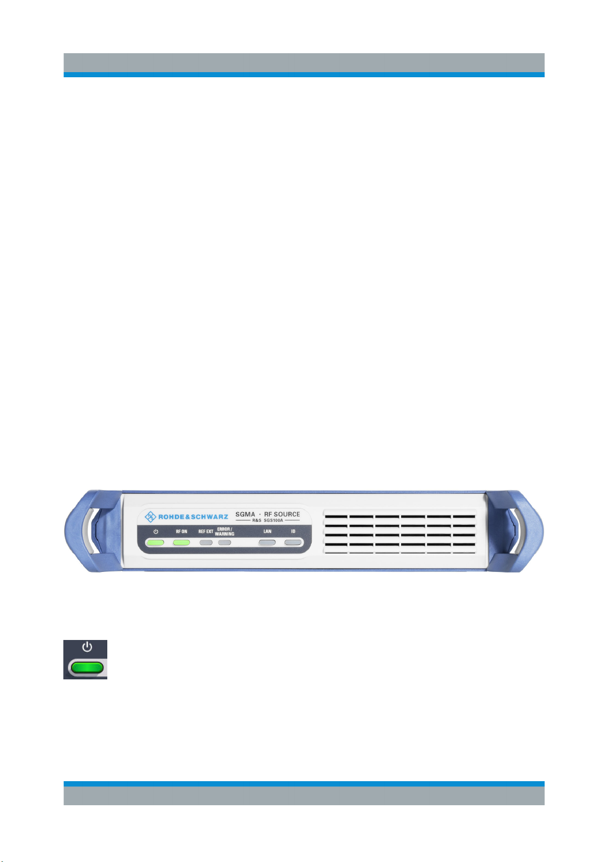
Figure 3-1: Front panel view
[POWER ON /STAND BY]
The [POWER ON /STAND BY] key switches the instrument from the standby to
ready state or vice versa.
In ready state, the button is green. The instrument is ready for operation.
26Getting Started 1416.0570.02 ─ 11
Page 29

R&S®SGS100A
In standby state, the button is orange. In this state, it is safe to switch off the AC
power and disconnect the instrument from the power supply.
A blinking green color indicates that a booting operation is in process.
[RF ON]
The [RF ON] key switches the RF signal on or off. If activated, the button is
green.
[REF EXT]
Instrument Tour
Front Panel Tour
The [REF EXT] LED indicates the status of the external reference.
●
Green indicates that the instrument can synchronize to the external clock.
●
Red indicates that the instrument cannot synchronize to the external clock.
●
No light indicates that the internal reference is used.
[ERROR / WARNING]
The [ERROR / WARNING] LED indicates the status of the R&S SGS.
●
Red indicates that an error has occurred, e.g. temperature exceeded or power
failure.
●
Blinking orange indicates a running process (e.g calibration, self test).
●
No light indicates that no errors or warnings have occurred.
For details on errors or warnings, refer to the graphical user interface on a remote
PC ("SGMA-GUI > Info").
For more information, refer to the "Error Messages" section in the user manual.
[LAN]
The [LAN] key indicates if a LAN connection is established.
27Getting Started 1416.0570.02 ─ 11
Page 30

R&S®SGS100A
Green LED indicates that a network cable is connected to the instrument and no
error in the DHCP connection is detected. But it does not indicate that the remote
control connection is established for all cases. For example, if the instrument is
set to use a "Static" IP address the instrument may still not be visible in the network.
Pressing the key resets the LAN interface settings, i.e the "IP Adress Mode" is
reset to DHCP.
[ID]
Pressing the [ID] key while the instrument is active, opens the "SGMA-GUI >
Setup > Instruments > Configure Instruments > Edit Instrument" dialog of the corresponding instrument on the remote controller.
Instrument Tour
Rear Panel Tour
Pressing the ID key of an inactive instrument and starting "SGMA-GUI > Setup >
Instruments > Scan", leads to an automatic activation of the instrument in the
SGMA-GUI.
3.2 Rear Panel Tour
This section provides an overview of the connectors on the rear panel of the
instrument. For technical data of the connectors, refer to the data sheet.
Figure 3-2: Rear panel view
Risk of damaging components
Always use an appropriate 8 mm torque wrench to tighten SMA connectors.
Limit the tightening torque to 60 Ncm. Never use an open-end wrench.
28Getting Started 1416.0570.02 ─ 11
Page 31

R&S®SGS100A
[PCI Express Connector]
The PCIe (Peripheral Component Interconnect Express) single lane interface
allows remote control with optimized speed.
For details, see Chapter 2.3.3, "Connecting a Controller via PCI Express",
on page 23.
[USB Connector]
The USB (universal serial bus) interface, type micro, allows you to connect various external devices, e.g.:
●
If the interface is configured as a device interface, the R&S SGS can be connected to other devices like a remote computer. On the computer, you can
perform a firmware update, manual operation via the R&S SGMA-GUI software or for remote control of the instrument.
●
If the interface is configured as a host interface, a memory stick for file transmission can be connected.
Instrument Tour
Rear Panel Tour
For details, see Chapter 2.3.4, "Connecting a Controller or a USB Device via
USB", on page 23.
[LAN Connector]
The [LAN] (Ethernet) interface allows you to connect the R&S SGS to other devices like a remote computer. On the computer, you can perform a firmware
update, manual operation via the R&S SGMA-GUI software or for remote control
of the instrument. The connection to the remote computer can be direct or via a
network.
For details, see Chapter 2.3.2, "Connecting a Remote PC via LAN", on page 19.
29Getting Started 1416.0570.02 ─ 11
Page 32

R&S®SGS100A
[RF OUT]
Provides an RF 50 Ohm signal output.
NOTICE! Maximum input levels. Do not overload the RF output. The maximum
permissible back-feed is specified in the data sheet.
[I , Q]
Instrument Tour
Rear Panel Tour
SMA female type connectors that are inputs of the I/Q modulator, provided for
feeding of external signal.
NOTICE! Maximum input levels. Do not overload the I and Q inputs. The maximum permissible voltage is 1V. For details, refer to the data sheet.
Note: The I/Q modulator requires one of the hardware options R&S SGS-B106V/-
B112V.
[REF / LO IN, REF / LO OUT]
SMA female type connectors, for reference or local oscillator signals, and alternatively also in MIMO setups.
Reference input and output:
●
[REF IN]: Input for external reference signal.
●
[REF OUT]: Output of internal reference signal.
Local oscillator input and output:
●
[LO IN]: Input for external LO signals
●
[LO OUT]: Output of internal LO signals.
Note: The local oscillator input/output requires the additional software option
R&S SGS-K90.
30Getting Started 1416.0570.02 ─ 11
Page 33

R&S®SGS100A
[TRIG]
Multi-purpose connector. The [TRIG] connector is used mainly as an input connector for an external pulse modulator source.
[AC supply and power switch]
The AC supply and power switch allow you to connect the R&S SGS to the power
supply and switch on the instrument.
Instrument Tour
Rear Panel Tour
For details, see "To connect the AC supply" on page 13.
31Getting Started 1416.0570.02 ─ 11
Page 34

R&S®SGS100A
Configuring a CW Signal with the R&S SGMA-GUI
First Steps with the Instrument
4 First Steps with the Instrument
This section provides examples on how to configure the R&S SGS to generate a
continuous wave (CW) signal via the R&S SGMA-GUI and the R&S SGS100A
Web-GUI.
4.1 Configuring a CW Signal with the R&S SGMA-
GUI
The R&S SGS in this example is a base unit equipped with the frequency option
R&S SGS-B106.
As a prerequisite for this example, the R&S SGS has to be connected to a remote
PC. The R&S SGMA-GUI software has to be installed on this remote PC and the
instrument is added to the list of "Available Instruments".
Figure 4-1: Example of the setup
For information on how to fulfill these requirements, refer to
●
Chapter 2.3.2.1, "Connecting the Instrument to the Network",
on page 19
●
Chapter 2.3.1, "Installing the R&S SGMA-GUI Software", on page 17
●
Chapter 2.3.2.3, "Automatically Adding Instruments to the SGMA-GUI ",
on page 22
1. Check the front panel of the R&S SGS.
32Getting Started 1416.0570.02 ─ 11
Page 35

R&S®SGS100A
Configuring a CW Signal with the R&S SGMA-GUI
The [POWER ON/STANDBY] and [LAN] key have to be green.
2. On the connected remote PC, start the R&S SGMA-GUI software application.
The main panel of the application opens. The panel provides a quick access
to the main settings of the configured and activated instruments. The display
shows one row per instrument with the instrument-specific settings. The rows
comprise the instrument, the connection state, the used frequency and power
level, the state of the RF output and the modulator and the used reference frequency source.
First Steps with the Instrument
3. In the R&S SGMA-GUI main panel, the green indicator in front of the instrument's name confirms that there is a connection between the instrument and
the remote PC and that the instrument is recognized by the software.
4. In the R&S SGMA-GUI main panel, select the row corresponding to the instrument to be configured and select "Instrument Name > Preset" to restore the
predefined instrument's settings.
5. In the R&S SGMA-GUI main panel, select the row corresponding to the instrument to be configured and adjust the "Frequency" as required.
33Getting Started 1416.0570.02 ─ 11
Page 36

R&S®SGS100A
Configuring a CW Signal with the R&S SGS100A Web-GUI
6. Select "SGMA-GUI > RF On" to enable the output of the CW signal.
The 5 GHz signal is output at the [RF OUT] connector at the rear panel of the
R&S SGS.
First Steps with the Instrument
Identifying a specific instrument
If several instruments are active in the R&S SGMA-GUI, use one of the
device identification functions to identify a specific device:
●
Select "SGMA-GUI > Instrument Name > Setup > Remote > Remote
Channels > Device Identify". The green [LAN] LED on the front panel of
the instrument blinks.
●
Press the [ID] key on the instrument's front panel. The "Edit Instrument"
dialog of the respective instrument opens.
4.2 Configuring a CW Signal with the R&S SGS100A
Web-GUI
The R&S SGS100A Web-GUI is an alternative way to operate the R&S SGS.
There is no installation needed. It can be used with all devices and operating systems, including tablets and smart phones, which have one of the following web
browsers installed:
●
Mozilla Firefox
●
Google Chrome
34Getting Started 1416.0570.02 ─ 11
Page 37

R&S®SGS100A
First Steps with the Instrument
Configuring a CW Signal with the R&S SGS100A Web-GUI
●
Microsoft Internet Explorer 9 or later
To connect to the R&S SGS from an external device, both of them must have
access to the same network, i.e. use a shared network.
The feature set of the R&S SGS100A Web-GUI is limited to the most common
settings, needed especially for modifying the output signal. For additional actions
like firmware updates or adjustments, please use the R&S SGMA-GUI.
You can operate the R&S SGS100A Web-GUI and the R&S SGMA-GUI simultaneously. Furthermore you can enable the "Update" function (upper right corner) to
allow an automatic update of the settings shown in the R&S SGS100A Web-GUI,
if the settings were changed via other software.
As a prerequisite for this example, the R&S SGS has to be connected to the
same network as the device used for controlling the instrument. Also one of the
supported web browsers has to be available.
1. Check the front panel of the R&S SGS.
The [POWER ON /STAND BY] and the [LAN] key have to be green.
2. Open a supported web browser.
3. Enter the instrument name or the IP address of the R&S SGS you want to
connect to.
Tip: The default hostname of the instrument is a non case-sensitive string
built as follows:
hostname = rssgs100a<serial number>, where
<serial number> is the individual serial number of the instrument.
The serial number is displayed at the rear side of the instrument. It is the third
part of the device ID printed on the bar code sticker, see Figure 4-2.
Figure 4-2: Serial number of the R&S SGS100A
The main panel of the R&S SGS100A Web-GUI opens.
35Getting Started 1416.0570.02 ─ 11
Page 38

R&S®SGS100A
Configuring a CW Signal with the R&S SGS100A Web-GUI
In the R&S SGS100A Web-GUI main panel, the green indicator "System Status > OK " confirms that there is a connection between the instrument and the
remote PC and that the instrument is recognized by the software.
If you want to get additional information about the instrument, click on the
"Device Name". For additional information on other settings, hold the mouse
cursor over the specific setting.
Error messages are also displayed in the R&S SGS100A Web-GUI. If you
want to hide an error message, click on it.
First Steps with the Instrument
4. In the menu bar on the left side press "Preset" to restore the predefined instrument's settings.
5. Select "Frequency" and adjust the setting as required.
6. Select "RF On" to enable the output of the CW signal.
A signal with the set frequency is output at the [RF OUT] connector at the rear
panel of the R&S SGS.
36Getting Started 1416.0570.02 ─ 11
Page 39

R&S®SGS100A
Manual Operation via R&S SGMA-GUI
Instrument Control
5 Instrument Control
As a rule, the R&S SGS is operated exclusively via programmatic remote control
from a connected PC. For service and diagnostic tasks, and for manual configuration, a graphical user interface (R&S SGMA-GUI) is provided which runs on the
remote PC.
Also, some basic functionality is provided via the keys on the front panel of the
instrument (see Chapter 3.1, "Front Panel Tour", on page 26).
5.1 Manual Operation via R&S SGMA-GUI
The R&S SGMA-GUI software application can be installed on a PC with Windows
or Linux operating system. This program allows you to control several devices of
the SGMA product family at the same time and to monitor the device status during remote control. R&S SGMA-GUI requires one of the external interfaces
described in Chapter 2.3, "Connecting an External PC and Devices", on page 16.
5.1.1 Introduction to the User Interface
After the start of R&S SGMA-GUI, the main dialog of the application is displayed.
Figure 5-1: Example of R&S SGMA-GUI
The main dialog with an overview of the configured instruments is the operating
and control interface for the whole program. From here, all program functions are
accessible.
The menus and dialogs are built using elements like selection lists, check boxes,
and entry fields. A blue frame indicates that the selected item is active. Entries
can be made in the highlighted element.
37Getting Started 1416.0570.02 ─ 11
Page 40

R&S®SGS100A
Manual Operation via R&S SGMA-GUI
The main dialog comprises two main areas:
●
On the top of the main panel, there are the menu bar, the tool bar and the info
bar with the corresponding "Info" button.
The menu bar provides access to the functions related to the software application itself, like saving current configurations, retrieving information about the
installed software version or configuring the connected instruments.
The messages displayed in the info line indicate information, warnings, and
errors. They are displayed in different colors depending on their importance
and display duration. Use the "Info" button to open a dialog with information
on the messages in greater detail.
●
The central part of the R&S SGMA-GUI main dialog is the main panel that
shows the list of all active instruments.
The main panel is the core element for the manual operation and provides
quick access to the main settings of the configured instruments. The display
shows one row per active instrument. Each row comprises the instrument's
name and state, the used frequency and level, the state of the RF output and
the modulator and the kind of used frequency reference.
The buttons with the instrument's symbolic name on it provides access to
menus and dialogs for further instrument configuration. Refer to the user manual for a detailed description of all parameters and functions provided for configuration.
Instrument Control
A detailed description of the R&S SGMA-GUI, in-depth information on how
to work with the application and on how to operate the R&S SGS is provided in the user manual.
5.1.2 How to Use the Help System
The R&S SGMA-GUI is equipped with a context-sensitive help function. A help
page is available for each parameter and can be called any time during instrument operation.
Calling context-sensitive and general help
► To display the general help dialog box, select the "SGMA-GUI > Help > Con-
tents" or use the F1 key.
The help dialog is displayed. A topic containing information about the current
menu or the currently opened dialog box and its function is displayed.
38Getting Started 1416.0570.02 ─ 11
Page 41

R&S®SGS100A
Instrument Control
Manual Operation via R&S SGMA-GUI
Contents of the help dialog box
The help dialog box contains two main areas:
●
"Contents" - contains a table of help contents
●
"Topic" - contains a specific help topic
The help system also provides an "Index", "Find" and "Zoom" functions that are
accessed with the corresponding buttons.
Navigating in the table of contents and in the help topics
1. To move through the displayed contents entries, use the mouse or the [Up/
Down] keys. Entries that contain further entries are marked with a plus sign.
2. To display a help topic, double click on the topic name or press the [ENTER]
key.
3. To jump to the linked topic, press the link text.
4. Use the "Previous" or "Next" links to jump to the corresponding topic.
5. Use the "Scroll Right" or "Scroll Left" buttons to shift the indicated area of the
navigation window to the left or right.
Using the index
1. Select "SGMA-GUI > Help > Index" or use the "Go to Index" button in the
"Help" display.
39Getting Started 1416.0570.02 ─ 11
Page 42

R&S®SGS100A
Instrument Control
Network and Remote Control Operation
2. Enter the first characters of the topic you are interested in. The entries starting
with these characters are displayed.
3. Press the [ENTER] key to display the help topic.
The corresponding help topic is displayed.
5.2 Network and Remote Control Operation
As an alternative to operating the R&S SGS interactively via the R&S SGMA-GUI,
one can also control the R&S SGS using programmed commands from a remote
PC.
The description in this section requires basic knowledge of the remote control operation. Definitions specified in the SCPI standard are not provided.
Nevertheless, you can find some basic information to the SCPI syntax,
command lists, and general programming recommendations in section
Remote Control Basics of the user manual. In addition, this chapter provides information on the status reporting system of the instrument.
5.2.1 Remote Control Interfaces and Protocols
The instrument supports several interfaces for remote control. The following table
gives an overview.
Table 5-1: Remote control interfaces and protocols
Interface Protocols Remarks
Local
Area Network
(LAN)
●
HiSLIP High-Speed LAN Instrument Protocol (IVI-6.1)
●
VXI-11
●
socket communication (Raw Ethernet,
simple Telnet)
A LAN connector is located on the
rear panel of the instrument.
The interface is based on TCP/IP
and supports various protocols.
For details, see Chapter 5.2.1.1,
"LAN Interface", on page 41
USB USBTMC A USB connector is located on the
rear panel of the instrument.
For details, see Chapter 5.2.1.2,
"USB Interface", on page 45
40Getting Started 1416.0570.02 ─ 11
Page 43

R&S®SGS100A
Instrument Control
Network and Remote Control Operation
Interface Protocols Remarks
PCIe Proprietary A PCIe connector is located on
the rear panel of the instrument.
For details, see Chapter 5.2.1.3,
"PCI Express Interface",
on page 45
GPIB
(IEC/
IEEE Bus
Interface)
– The instrument is not equipped
with GPIB bus interfaces. Use a
GPIB-to-LAN or GPIB-to-USB
adapter instead.
For details, see Chapter 5.2.1.4,
"GPIB Interface (IEC/IEEE Bus
Interface)", on page 46
SCPI (Standard Commands for Programmable Instruments)
SCPI commands are used for remote control. Commands that are not taken from
the SCPI standard follow the SCPI syntax rules. The instrument supports the
SCPI version 1999. The SCPI standard is based on standard IEEE 488.2 and
aims at the standardization of device-specific commands, error handling and the
status registers. The tutorial "Automatic Measurement Control - A tutorial on SCPI
and IEEE 488.2" from John M. Pieper (R&S order number 0002.3536.00) offers
detailed information on concepts and definitions of SCPI.
5.2.1.1 LAN Interface
To be integrated in a LAN, the instrument is equipped with a LAN interface, consisting of a connector, a network interface card and protocols.
For remote control via a network, the PC and the instrument must be connected
via the LAN interface to a common network with TCP/IP network protocol. They
are connected using a RJ45 cable (shielded or unshielded twisted-pair category
5). The TCP/IP network protocol and the associated network services are precon-
figured on the instrument. Software for instrument control and (for specified protocols only) the VISA program library must be installed on the controller.
Identifying instruments in a network
If several instruments are connected to the network, each instrument has its
own IP address and associated resource string. The controller identifies
these instruments by the resource string.
41Getting Started 1416.0570.02 ─ 11
Page 44

R&S®SGS100A
Network and Remote Control Operation
VISA Resource Strings
The VISA resource string is required to establish a communication session
between the controller and the instrument in a LAN. The resource string is a
unique identifier, composed of the specific IP address of the instrument and some
network and VISA-specific keywords.
TCPIP::host address[::LAN device name][::INSTR]
●
TCPIP designates the network protocol used
●
host address is the IP address or host name of the device
●
[::LAN device name] defines the protocol and the instance number of a subinstrument:
●
[::INSTR] indicates the instrument resource class (optional)
The IP address (host address/computer name) is used by the programs to identify and control the instrument. It is automatically assigned by the DHCP server
the first time the device is registered on the network. Alternatively, you can also
assign its LAN device name.
Instrument Control
You can find the IP address in the "SGMA-GUI > Instrument Name > Setup >
Remote" dialog, and also adjust it manually, if necessary.
See below the characteristics of the VISA resource strings for the corresponding
interface protocols. The highlighted characters are crucial.
HiSLIP
TCPIP::host address::hislip0[::INSTR]
●
hislip0 HiSLIP device name, designates that the interface protocol HiSLIP is
used (mandatory).
hislip0 is composed of [::HiSLIP device name[,HiSLIP port]] and must be
assigned.
For details of the HiSLIP protocol, refer to "HiSLIP Protocol" on page 43.
VXI-11
TCPIP::host address[::inst0][::INSTR]
●
[::inst0] LAN device name, indicates that the VXI-11 protocol is used
(optional).
inst0 currently selects the VXI-11 protocol by default and can be omitted.
42Getting Started 1416.0570.02 ─ 11
Page 45

R&S®SGS100A
Network and Remote Control Operation
For details of the VXI-11 protocol, refer to ."VXI-11 Protocol" on page 44
Socket communication
TCPIP::host address::port::SOCKET
●
port determines the used port number
●
SOCKET indicates the raw network socket resource class
Socket communication requires the specification of the port (commonly referred
to as port number) and of "SOCKET" to complete the VISA resource string with
the associated protocol used.
The registered port for socket communication is port 5025.
See also "Socket Communication" on page 44.
Example:
Instrument Control
●
Instrument has the IP address 10.113.11.91; the valid resource string using
VXI-11 protocol is:
TCPIP::10.113.11.91::INSTR
●
The DNS host name is rssgs100a100021; the valid resource string is:
TCPIP::rssgs100a100021::hislip0 (HiSLIP)
TCPIP::rssgs100a100021::inst0 (VXI-11)
●
A raw socket connection can be established using:
TCPIP::10.113.11.91::5025::SOCKET
HiSLIP Protocol
The HiSLIP (High Speed LAN Instrument Protocol) is the successor protocol for
VXI-11 for TCP-based instruments specified by the IVI foundation. The protocol
uses two TCP sockets for a single connection - one for fast data transfer, the
other for non-sequential control commands (e.g. Device Clear or SRQ).
HiSLIP has the following characteristics:
●
High performance as with raw socket network connections
●
Compatible IEEE 488.2 support for Message Exchange Protocol, Device
Clear, Serial Poll, Remote/Local, Trigger, and Service Request
●
Uses a single IANA registered port (4880), which simplifies the configuration
of firewalls
●
Supports simultaneous access of multiple users by providing versatile locking
mechanisms
43Getting Started 1416.0570.02 ─ 11
Page 46

R&S®SGS100A
Network and Remote Control Operation
●
Usable for IPv6 or IPv4 networks
Using VXI-11, each operation is blocked until a VXI-11 device handshake
returns. However, using HiSLIP, data is sent to the device using the "fire
and forget" method with immediate return. Thus, a successful return of a
VISA operation such as viWrite() does not guarantee that the instrument has finished or started the requested command, but is delivered to the
TCP/IP buffers.
For more information see also the application note:
1MA208: Fast Remote Instrument Control with HiSLIP
VXI-11 Protocol
The VXI-11 standard is based on the ONC RPC (Open Network Computing
Remote Procedure Call) protocol which in turn relies on TCP/IP as the network/
transport layer. The TCP/IP network protocol and the associated network services
are preconfigured. TCP/IP ensures connection-oriented communication, where
the order of the exchanged messages is adhered to and interrupted links are
identified. With this protocol, messages cannot be lost.
Instrument Control
Socket Communication
An alternative way for remote control of the software is to establish a simple network communication using sockets. The socket communication, also referred to
as “Raw Ethernet communication”, does not require a VISA installation on the
remote controller side.
The simplest way to establish socket communication is to use the built-in telnet
program. The telnet program is part of every operating system and supports communication with the software on a command-by-command basis.
Socket connections are established on a specially defined port. The socket
address is a combination of the IP address or the host name of the instrument
and the number of the port configured for remote-control. All instruments use port
number 5025 for this purpose. The port is configured for communication on a
command-to-command basis and for remote control from a program running on a
connected PC.
44Getting Started 1416.0570.02 ─ 11
Page 47

R&S®SGS100A
Network and Remote Control Operation
5.2.1.2 USB Interface
For remote control via USB connection, the PC and the instrument must be connected via the USB interface. A USB connection requires the VISA library to be
installed. VISA detects and configures the R&S instrument automatically when
the USB connection is established. You do not have to install a separate driver.
You can retrieve the USB resource string from the "SGMA-GUI > Instrument
Name > Setup > Remote" dialog.
Example:
USB::0x0AAD::0x0088::100021::INSTR
0x0AAD is the vendor ID for Rohde&Schwarz
0x0088 is the product ID for the R&S SGS
100021 is the serial number of the particular instrument
Instrument Control
5.2.1.3 PCI Express Interface
A PCI Express (PCIe) connector is provided on the rear panel of the instrument.
Refer to chapter "Advanced Remote Control via PCIe" of the user manual for a
description of how to set up a remote control connection via PCIe and the permitted cables.
Via PCI Express some commands can be sent to the instrument with optimized
speed (memory-mapped remote control), e.g. frequency or level settings. This
allows minimum setup time.
You can retrieve the PCIe resource string from the "SGMA-GUI > Instrument
Name > Setup > Remote" dialog.
Example:
PCIe::0x162f::0x132e::100021::INSTR
0x162f is the vendor ID for Rohde&Schwarz
0x132e is the product ID for the R&S SGS
100021 is the serial number of the particular instrument
45Getting Started 1416.0570.02 ─ 11
Page 48

R&S®SGS100A
Network and Remote Control Operation
Using the PCIe interface for remote control of the instrument requires
extended knowledge and is described in section "Advanced Remote Control via PCIe" in the user manual.
5.2.1.4 GPIB Interface (IEC/IEEE Bus Interface)
The R&S SGS is not equipped with an IEC/IEEE bus interface.
To be able to control the instrument via the GPIB bus:
1. Connect a GPIB-to-LAN or a GPIB-to-USB adapter to the instrument.
2. Use a GPIB bus cable to connect the instrument and the controller.
3. Provide the GPIB bus card, the card drivers and the program libraries for the
programming language in the controller.
Instrument Control
4. In the "SGMA-GUI > Setup > Instruments > instrument name > Remote Control", set the "GPIB Address".
5. If the controller is equipped with several GPIB bus cards, define the used
"Board Number".
GPIB address
The controller must address the instrument with the GPIB bus channel. GPIB provides channel addresses from 0 to 30.
The GPIB resource string is GPIB::<address>[::INSTR], where:
●
GPIB denotes the used interface
●
<address> indicates the used channel
●
[::INSTR] indicates the instrument resource class (optional)
Note: If the VISA implementation supports the GPIB interface, you can optionally
define the VISA instrument control resource (INSTR). It is used to define the
basic operations and attributes for a device, such as reading, writing, or triggering.
Any connected IEC bus cable must be terminated by an instrument or controller.
46Getting Started 1416.0570.02 ─ 11
Page 49

R&S®SGS100A
Network and Remote Control Operation
Instrument Control
5.2.2 Example: Remote Control over LAN Using the VXI-11 Pro-
tocol
In the following example, the program "Measurement & Automation Explorer"
from National Instruments is used on a Windows operating system to set up a
LAN remote control link and to start a remote control session. The remote control
program "Measurement & Automation Explorer" opens the connection to the
instrument (using VISA functionality) and then sends commands to and receives
device responses from the instrument.
A remote control connection requires a VISA installation but no additional hardware on the controller PC. The LAN I/O channel is selected at initialization time
using the VISA resource string (also referred to as "address string"). A VISA alias
(short name) is used to replace the complete resource string. The host address is
either the R&S SGS's computer name or its IP address.
Proceed as described in Chapter 2.3.2.2, "Assigning the IP Address", on page 21
to determine the relevant address information.
In this example, it is assumed that:
●
A LAN remote control link between the controller and the R&S SGS is
already set up.
For information on setting up the link, see Chapter 2.3.2, "Connecting a
Remote PC via LAN", on page 19.
●
A VISA and the "Measurement & Automation Explorer" program are
installed on the remote PC.
For detailed information, refer to section "Remote Control Basics" in the
user manual or to the online help of the "Measurement & Automation
Explorer" program.
To configure the controller
The instrument is preconfigured for networks using DHCP (dynamic host
configuration protocol). If this configuration is used, enter the computer
name in the position of the IP address.
47Getting Started 1416.0570.02 ─ 11
Page 50

R&S®SGS100A
Network and Remote Control Operation
To enable the external controller to communicate with the software via TCP/IP
protocol, set up a remote control link as follows:
1. Connect the controller and the instrument to the network (network cable).
Switch them on.
2. Start the 'Measurement & Automation Control' program on the controller.
3. Select "Devices and Interfaces > Create New".
4. Select "VISA TCP/IP Resource" and confirm with "Next".
Instrument Control
5. Choose the type of TCP/IP resource you wish to add and select "Next".
6. Enter the IP address or the host name of the R&S SGS and select "Next".
7. Enter the alias name if necessary.
48Getting Started 1416.0570.02 ─ 11
Page 51

R&S®SGS100A
Network and Remote Control Operation
The alias name should not be mistaken for the computer name. It is only used
for instrument identification within the program and displayed in the menu as
an option if there is an Ethernet link.
8. Confirm the settings with "Finish".
The instrument is configured and the settings are displayed in the "TCP/IP
Settings" tab.
Instrument Control
9. To test the connection, select "Validate".
A message indicates whether the link to the instrument can be set up or not.
If a connection cannot be set up, check whether the controller and the instrument are connected to the network (network cable) and are switched on. Correct spelling of the IP address or the computer name should be checked. For
further error location, inform the network administrator. In large networks,
specification of additional addresses may be required for link setup, e.g. gateway and subnet mask, which are known to the network administrator.
The instrument is now registered in the program and can be addressed via the
resource string or alias name.
To start a remote control session over LAN (using VXI-11)
1. Start the "Measurement & Automation Explorer" on the controller.
49Getting Started 1416.0570.02 ─ 11
Page 52

R&S®SGS100A
Network and Remote Control Operation
2. In the "Configuration" window, select "Device and Interfaces > VISA TCP/IP
Resources", select the required instrument and select "Open VISA Test
Panel".
Instrument Control
3. In the "viWrite" tab, write the command to be sent to the instrument and select
"Execute".
Instrument responses are displayed on the "viRead" tab.
Tip: For further program operation, refer to the online help of the program.
50Getting Started 1416.0570.02 ─ 11
Page 53

R&S®SGS100A
Index
Index
A
AC supply .......................................... 13, 31
Application cards ....................................... 7
Application notes ....................................... 7
B
Brochures .................................................. 7
C
Connector
I ...........................................................30
LAN .....................................................29
LO IN .................................................. 30
LO OUT .............................................. 30
PCIe ....................................................29
Q ......................................................... 30
REF IN ................................................ 30
REF OUT ............................................ 30
RF OUT .............................................. 30
TRIG ................................................... 31
USB .................................................... 29
Connectors .............................................. 28
D
Data sheets ............................................... 7
Default instrument settings ......................15
DHCP ...................................................... 21
Documentation overview ........................... 5
E
Electrostatic discharge ............................ 10
EMI suppression ......................................10
Error
Key ......................................................27
ESD ......................................................... 10
External controller ................................... 16
External devices ...................................... 16
External reference
Connector ..................................... 27, 30
F
Function check ........................................ 15
G
Getting started ...........................................6
GPIB ........................................................40
Characteristics .................................... 46
H
Hardware
Requirements ..................................... 18
Help ........................................................... 6
HiSLIP ..................................................... 40
Protocol ...............................................43
Resource string ...................................42
I
I / Q
Connectors ......................................... 30
ID
Key ......................................................28
Input connector ........................................30
Input/Output connector ............................31
Installing
Hardware ............................................ 18
R&S SGMA-GUI ................................. 17
Requirements ..................................... 18
Software ..............................................18
Uninstalling the old version .................17
Update ................................................ 17
Instrument help ..........................................6
Instrument security procedures ................. 6
Interfaces
GPIB ................................................... 46
USB .................................................... 45
IP address ............................................... 42
Changing ............................................ 21
K
Key
ID ........................................................ 28
LAN .....................................................27
POWER ON ........................................26
POWER ON/STANDBY ...................... 26
RF ON .................................................27
L
LAN
Configuration ...................................... 19
Connector ........................................... 29
Interface ..............................................41
IP address ...........................................42
51Getting Started 1416.0570.02 ─ 11
Page 54

R&S®SGS100A
Index
Key ......................................................27
VXI protocol ........................................ 44
LED
ERROR / WARNING ...........................27
REF EXT .............................................27
Linux ........................................................16
LO
Connector ........................................... 30
M
MIMO
Connector ........................................... 30
O
Online help
Working with ....................................... 38
Open source acknowledgment ..................7
Operating system .................................... 16
OSA ...........................................................7
Output connector .....................................30
P
PCIe
Connecting ..........................................23
Connector ........................................... 29
Power On
Key ......................................................26
Power switch ..................................... 13, 31
Preset instrument settings .......................15
Protocol
VXI ...................................................... 44
R
S
Safety instructions ..................................... 7
SCPI
Version ................................................ 41
SCPI disabled ..........................................18
Service manual ..........................................6
Shutting down ..........................................14
Socket ..................................................... 40
Software
Requirements ..................................... 18
VISA driver ..........................................18
Standby ................................................... 13
Key ......................................................26
T
Telnet ....................................................... 40
Trigger
Connector ........................................... 31
U
Updating R&S SGMA-GUI ...................... 17
USB
Connecting ..........................................23
Connector ........................................... 29
Interfaces ............................................ 45
User manual .............................................. 6
V
VISA ........................................................ 40
Resource string ...................................42
VXI protocol .............................................44
VXI-11 ...................................................... 40
Rack mounting ........................................ 12
Ready state ............................................. 13
REF
Connector ........................................... 30
REF EXT
Key ......................................................27
Release notes ........................................... 7
Remote control
Connect .............................................. 40
Reset instrument settings ........................15
Resource string
VISA ....................................................42
RF ON
Key ......................................................27
RF OUT
Connector ........................................... 30
W
White papers ............................................. 7
Z
Zeroconf (APIA) protocol .........................21
52Getting Started 1416.0570.02 ─ 11
 Loading...