

Page 1

RS Stock No. 730-0458
Instruction Manual
RS-1384
4 Input Data Logging Thermometer
FREN
IT
DE
ES
Page 2

TABLE OF CONTENTS / EN
09/16/11 Version No. 00
TABLE OF CONTENTS
TITLE PAGE
1. INTRODUCTION FEATURE .............................................................1
2. SPECIFICATIONS ............................................................................2
2-1 Electronic Specifications..............................................................2
2-2 General Specifications.................................................................3
3. PARTS & CONTROLS......................................................................4
3-1 Description of Parts & Control keys.............................................4
3-2 Description of Display..................................................................5
4. OPERATION INSTRUCTION............................................................7
4-1 Setting the Meter.........................................................................7
4-2 Setting the Thermocouple Type...................................................9
4-3 Temperature Measurement .........................................................9
4-4 Maximum (MAX), Minimum (MIN) Recording Measurement........9
4-5 Manual Data Memory and Read Function Operation.................10
4-6 Auto Datalogging Function Operation........................................10
4-7 Disable Auto Power off Function................................................ 11
5. MAINTENANCE..............................................................................12
5-1 General Maintenance................................................................12
5-2 Battery Replacement.................................................................12
6. SOFTWARE INSTALLATION AND OPERATION ...........................13
Page 3

INTRODUCTION FEATURE / EN
09/16/11 Version No. 00 EN-1
1. INTRODUCTION FEATURE
This instrument is a digital 4 input thermometer and datalogger for working with any K, J, E,
T, R, S, N, L, U, B and C-type thermocouple as temperature sensor.
Temperature indication follows the international temperature scale of 1990. (ITS-90)
Read the following safety information carefully before attempting to operate or service the
meter.
Use the meter only as specified in this manual; otherwise, the protection provided by the
meter may be impaired
Environment conditions
Altitude up to 2000 meters
Relatively humidity 80% max.
Operation Ambient 0 to 50°C (32 to 122°F)
Features
Isolated Input Protection of 350Vp-p between any two inputs.
Highly accurate thermometer with thermocouple K, J, E, T, R, S, N, L, U, B, C types.
4 input function T1/T2/T3/T4 temperature display.
Programmable Hi – Lo alarm for 4 inputs.
Display of MAX, MIN and MAX–MIN values of 4 inputs.
Independent Input Setup (type of thermocouple, Hi – Lo alarm values).
Memory and Read function (99 sets).
512KB auto data logging capacity.
USB interface.
Safety symbols
When servicing, use only specified replacement parts.
Complies with EMC
Page 4

SPECIFICATIONS / EN
EN-2 09/16/11 Version No. 00
2. SPECIFICATIONS
2-1 Electronic Specifications
°C °F
Type
Range Accuracy Range Accuracy
K
-200 to -150
-150 to -100
-100 to 999.9
1000 to 1370
±3.0°C
±2.0°C
±0.05% ±1.0°C
±0.2% ±1.0°C
-328 to -238
-238 to -148
-148 to 999.9
1000 to 2498
±5.4°F
±3.6°F
±0.05% ±1.8°F
±0.2% ±1.8°F
J
-200 to -100
-100 to 100
100 to 999.9
±2.5°C
±1.5°C
±0.05% ±1.0°C
-328 to -148
-148 to 212
212 to 999.9
1000 to 1832
±4.5°F
±2.7°F
±0.05% ±1.8°F
±0.2% ±1°F
E
-150 to -100
-100 to 760
±3.0°C
±0.05% ±1.0°C
-238 to -148
-148 to 999.9
1000 to 1400
±5.4°F
±0.05% ±1.8°F
±0.2% ±1°F
T
-200 to -150
-150 to -100
-100 to 400
±3.0°C
±0.15% ±2.5°C
±0.1% ±1.0°C
-328 to -238
-238 to -148
-148 to 752
±5.4°F
±0.15% ±4.5°F
±0.1% ±1.8°F
R/S
0 to 100
100 to 300
300 to 999.9
1000 to 1600
±5.0°C
±3.0°C
±0.05% ±2.0°C
±0.25% ±2.0°C
32 to 212
212 to 572
572 to 999.9
1000 to 2912
±9.0°F
±5.4°F
±0.05% ±3.6°F
±0.25% ±3.6°F
N
0 to 999.9
1000 to 1300
±0.1% ±1.0°C
±0.2% ±1.0°C
32 to 999.9
1000 to 2372
±0.1% ±1.8°F
±0.2% ±1.8°F
L -200 to 900 ±0.1% ±1.0°C
-328 to 999.9
1000 to 1652
±0.1 % ±1.8°F
±0.2% ±1°F
U 0 to 600 ±0.1% ±1.0°C
32 to 999.9
1000 to 1112
±0.1% ±1.8°F
±0.2% ±1°F
B
600 to 999.9
1000 to 1760
±0.05% ±2.0°C
±0.1% ±2.0°C
1112 to 1831
1832 to 3200
±0.05% ±3.6°F
±0.1% ±3.6°F
C
0 to 999.9
1000 to 1760
±0.1% ±1.5°C
±0.2% ±1.5°C
32 to 999.9
1000 to 3200
±0.1% ±2.7°F
±0.2% ±2.7°F
NOTE
This basic accuracy specification does not include the error of the temperature probe.
Please refer to the temperature probe accuracy specification for additional details.
Temperature Coefficient :
0.01% of reading +0.1°C per °C (0.2°F per °F)
Outside the specified +18 to 28°C (+64 to 82°F) range.
Isolated Input Protection between any two inputs
: 350Vp-p
Manual Data Memory capacity: 99 sets.
Continuous Data logging capacity: 36,000 sets.
Page 5

SPECIFICATIONS / EN
09/16/11 Version No. 00 EN-3
2-2 General Specifications
Power Supply: 6 pcs size AA battery or DC 9V AC adaptor.
Battery life: approx. 55 hours (Alkaline battery)
Auto Power off: 5, 15 or 30 minutes. (If no key is pressed).
Low Battery Indication: The ( ) is displayed when the battery voltage drops below the
operating voltage.
Measurement Rate: Once per 2 seconds.
Weight: 405g / 14.3oz (batteries included)
Dimension: 18.7×7.3×5.3 cm
Operating Temperature and Humidity: 0 to 50°C (32 to 122°F), below 80% RH
Storage Temperature and Humidity: -10 to 60°C (14 to 140°F), below 70% RH
Accessories: Instruction manual, alkaline battery, USB cable, Software CD, Carrying case,
1 x K-type thermocouple
Page 6

PARTS & CONTROLS / EN
EN-4 09/16/11 Version No. 00
3. PARTS & CONTROLS
3-1 Description of Parts & Control keys
ALARM
-
INTV
m:s
d-h
FULL
NO.
T 4T 3
T 2T 1
MAX MIN
5
13
10
11
7
4
3
6
15
14
12
9
2
1
8
(1). LCD Display
(2).
key : Power on – off control key.
(3). ⊳ ↵↵↵↵ keys
: Setting keys.
(4). HOLD key
Data hold function key, press the “
HOLD
” key to hold data, the “ H ” symbol is displayed, press this
key again to exit this function.
Press and hold down the “HOLD” key then press “ ” key to turn on the meter, the “ ”
symbol disappears, and the auto power off function is disabled.
Page 7

PARTS & CONTROLS / EN
09/16/11 Version No. 00 EN-5
(5). MAX MIN key: Press the “MAX MIN” key to scroll though the display of MAX, MIN and
MAX–MIN and current readings. Press this key for 2 seconds to exit this
mode.
(6). ° C / ° F key: Press “° C / ° F” key to switch the units between Celsius (°C) and Fahrenheit
(°F).
(7). TYPE key: Press “TYPE” key to enter the thermocouple type select mode, press this key
again to exit this mode.
(8). TIME Key: Press “TIME” key to scroll through the display data and time.
(9). ALARM key: Press “ALARM” key to enable or disable Alarm function.
(10). MEM key: Manual data storage control key.
(11). SET key: Press “SET” key to start or exit setup.
(12). READ key: Manual data storage reading control key.
(13). T1, T2, T3, T4 : Thermocouple inputs.
(14). USB interface jack.
(15). External Power adaptor input jack.
3-2 Description of Display
ALARM
-
INTV
m:s
d-h
FULL
NO.
T 4
T 3
T 2T 1
MAX MIN
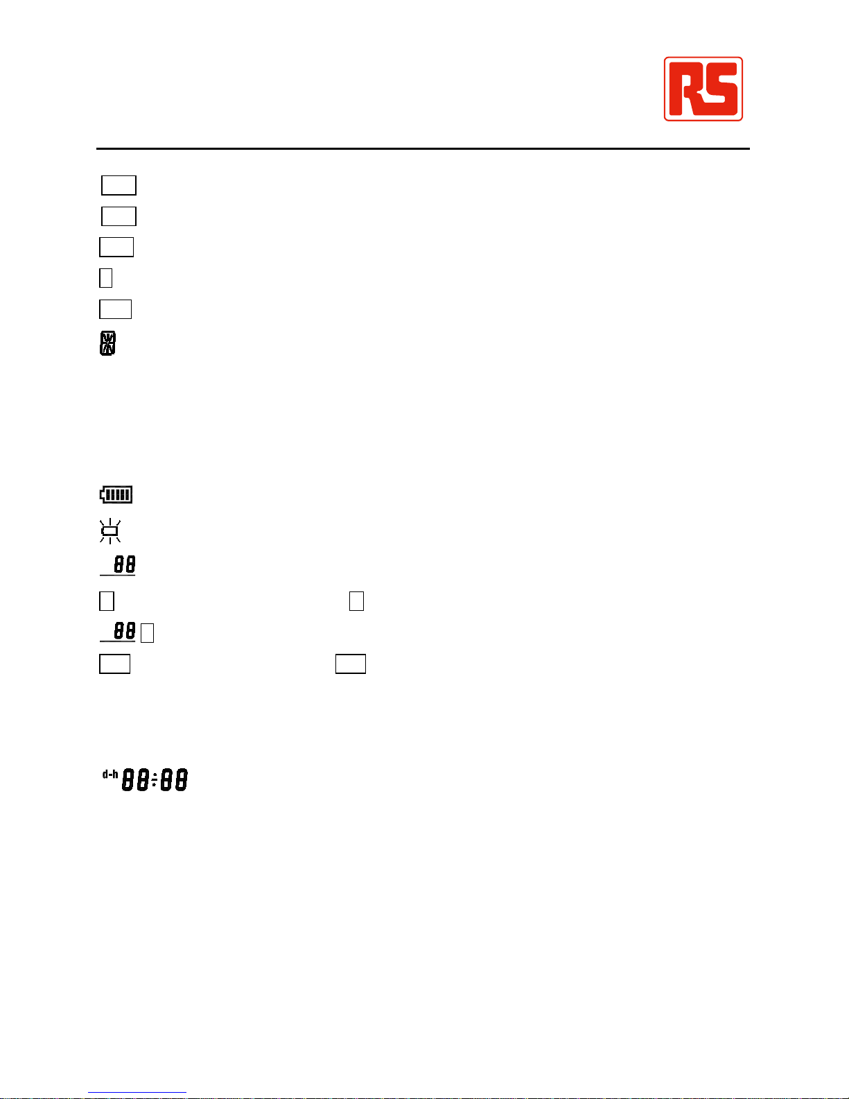
° F, ° C: Temperature units.
: Auto power off indication.
OFFSET: The thermocouple measurement includes an offset indication.
REC: MAX MIN Recording mode and current reading indication.
Page 8
PARTS & CONTROLS / EN
EN-6 09/16/11 Version No. 00
REC MAX: Maximum reading indication.
REC MIN: Minimum reading indication.
REC MAX-MIN: Maximum minus Minimum value indication.
H: Data hold function indication.
SET: Setting mode indication.
: Thermocouple type indication.
ALARM: Alarm mode indication.
ALARM: Input temperature exceeds the High limit value indication.
ALARM: Input temperature is below the Low limit value indication.
T1, T2, T3, T4: Thermocouple input temperature measurement display.
: Battery capacity indication.
: Replace batteries indication.
NO.
: Last manual data memory address number (01–99).
M: Manual data memory indication, M indicates that data is stored in memory.
NO.
R: Indicates the current manual data memory address block.
A-M: Auto datalogging indication, A-M indicates auto datalogging is in use.
Full: Auto datalogging memory full indication. The continuous datalogging has exceed 255
memory blocks, the total maximum record capacity size is 36,000 data sets using
all 4 thermocouple temperature measurement inputs. (100,000 sets of data using
only 1 input).
m:s
: Time display indication.
INTV: Auto data log interval time setting indication.
Page 9
OPERATION INSTRUCTION / EN
09/16/11 Version No. 00 EN-7
4. OPERATION INSTRUCTION
WARNING
Before using the meter inspect the case. Do not use the meter if it appears damaged.
Look for cracked or missing plastic. Pay particular attention to the insulation around the
connectors.
Disconnect thermocouples from the meter before opening the case.
Replace the batteries as soon as the battery indicator “ ” appears as accurate
measurements may no longer be possible.
Do not use the meter if it operates abnormally. Protection may be impaired.
Do not operate the meter around explosive gas, vapour or dust.
Do not use the meter with any part of the case or cover removed.
4-1 Setting the Meter
1. Real – Time setting:
(a). Press “” key to turn on the meter.
(b). Press “SET” key to enter the setting mode, the “Set clock” and “ SET ” symbols are
displayed.
(c). Press “
↵↵↵↵
” key to enter the real – time setting mode, the two year digits will flash.
(d). Press or key to set the year of the real – time.
(e). Press “
↵↵↵↵
” key, to store the year and select month.
(f). Press or key to set the month of the real – time.
(g). Press “
↵↵↵↵
” key, to store the month and select day.
(h). Press or key to set the day of the real – time.
(i). Press “
↵↵↵↵
” key, to store the day and select hour.
(j). Press or key to set the hour of the real – time.
(k). Press “
↵↵↵↵
” key to store the hour and select minutes.
(l). Press or key to set the minute of the real – time.
(m). Press “
↵↵↵↵
”
key to store the minutes and select seconds.
(n). Press or key to set the second of the real – time.
(o). Press “
↵↵↵↵
” key to store the seconds.
(r). Press “SET” key to exit this mode.
2. Interval – Time setting:
The logging interval time determines how often the meter stores logged readings in
memory.
(a). Press “
”
key to turn on the meter.
(b). Press “SET” key to enter the setting mode, then press or key until the display
shows “Set Intr”.
Page 10

OPERATION INSTRUCTION / EN
EN-8 09/16/11 Version No. 00
(c). Press “
↵↵↵↵
”
key to enter the interval time setting mode and the three flashing numbers of
seconds.
(d). Press or key to set the desired second of interval time (1 to 255 seconds).
(e). Press “
↵↵↵↵
” key to store the auto datalogging interval time.
(f). Press “SET” key to exit this mode.
3. Offset setting:
You can adjust the meter readings to compensate for the errors of a specific thermocouple.
The allowable adjustment range is from +12.7 to -12.8 degree and regardless the
temperature units. You can store individual offsets for T1, T2, T3 and T4.
(a). Press “” key to turn on the meter.
(b). Press “SET” key to enter the setting mode, then press or key until the display shows
“SEt OFSEt”.
(c). Press “
↵↵↵↵
” key to enter the offset setting mode, the “ OFFSET ” symbol is displayed.
(d). Press ⊳ or key to select the desired T1, T2, T3 or T4.
(e). Press or key to set the desired offset values.
(f). Press “
↵↵↵↵
” key to store the offset value.
(g). Press “SET” key to exit this mode.
The temperature measurement plus the offset appears in the display. Remember to set the
offset to 0.0 when it is no longer needed. The “ OFFSET ” symbol will disappear when the
offset values all are 0.0.
4. Auto Power Off Time setting:
(a). Press “ ” key to turn on the meter.
(b). Press “SET” key to enter the setting mode, then press or key until the display shows
“SEt SLEEP”.
(c). Press “
↵↵↵↵
” key to enter the auto power off time setting mode, the “SLEEP” symbol is
displayed.
(d). Press or key to choose the desired auto power off time. The choices are : 5, 15 and
30 minutes.
(e). Press “
↵↵↵↵
” key to store the choice.
(f). Press “SET” key to exit this mode.
5. Alarm High / Low Limit setting:
(a). Press “ ” key to turn on the meter.
(b). Press “SET” key to enter the setting mode, then press or key until the display shows
“SEt ALArn”.
(c). Press “
↵↵↵↵
" key to enter the alarm high limit and low limit setting mode, the “ ALARM ”
symbol is displayed.
(d). Press ⊳ or key to select the desired T1, T2, T3 or T4.
(e). Press “
↵↵↵↵
” key to enter the high limit value setting, the “” symbol is displayed.
Page 11

OPERATION INSTRUCTION / EN
09/16/11 Version No. 00 EN-9
(f). Press or key to set the desired alarm high limit value, the resolution of setting value
is 0.1 degree regardless of the temperature units.
(g). Press “
↵↵↵↵
” key to store the alarm high limit value and to enter the alarm low limit value
setting, the symbol “” is displayed.
(h). Press or key to set the desired alarm low limit value, the resolution of setting value
is 0.1 degree regardless of the temperature units.
(i). Press “
↵↵↵↵
” key to store alarm low limit value. Repeat procedures (c) to (i) to store
individual alarm High / Low limit values for T1, T2, T3 and T4.
(j). Press “SET” key to exit this mode.
(k). Press “ALARM” key to enter the alarm function, the “ALARM” symbol is displayed.
When the measured temperature value exceeds the setting High temperature value
(the “” symbol will flashing display.) or below the setting Low temperature value (the
“” symbol will flashing display.) a beep will sound once every 4 seconds.
(l). Press “ALARM” key again to exit the alarm function.
4-2 Setting the Thermocouple Type
1. Press “ ” key to turn on the meter.
2. Press “TYPE” key to enter the thermocouple type choices.
The currently selected thermocouple type blinks.
3. Press ⊳ or key to select the desired T1, T2, T3 or T4.
4. Press or key until the thermocouple type you want appears on the display.
5. Press “
↵↵↵↵
” key to store the thermocouple type. Repeat procedures (3) to (5) to store
individual thermocouple types for T1, T2, T3 and T4.
6. Press “TYPE” key again to exit.
4-3 Temperature Measurement
1. Press “ ” key to turn on the thermometer.
2. Plug the thermocouple(s) into the thermocouple input. If no thermocouple is plugged into
the selected input or the thermocouple is “open”, the display will show “- - -”.
3. Press “° C / ° F” key to desired temperature scale.
4. Perform measurements by contacting the object being measured with the probe sensor.
5. Read the temperature on the display. The display shows “OL” (overload) or “Un” (under
range) when the temperature being measured is outside the meter valid range.
4-4 Maximum (MAX), Minimum (MIN) Recording Measurement
1. Press “MAX MIN” key to enter the recording mode, the “ REC ” symbol is displayed.
2. Press “MAX MIN” key to scroll through the display of the maximum (REC
MAX), minimum
(REC MIN), maximum minus minimum (REC MAX-MIN) and current REC) reading.
3. Press “HOLD” key to paused recording, the “H” symbol is displayed, press “HOLD” key
again to resume recording.
4. Press “MAX MIN” key for 2 seconds to exit this mode.
Page 12

OPERATION INSTRUCTION / EN
EN-10 09/16/11 Version No. 00
4-5 Manual Data Memory and Read Function Operation
1. Clearing the manual memorized data
(a). Press “ ” key to turn off the meter.
(b). Press and hold down “MEM” key, then press “ " key again to turn on the meter, the “CLr
YES no M” symbol is displayed.
(c). Press ⊳ or key to select “YES” symbol is displayed flashing.
(d). Press “
↵↵↵↵
” key to clear the manually stored data.
(e). Press “
↵↵↵↵
” key again to exit this mode.
2. Store manual data to memory
(a). Press “MEM” key once to store the sets of measured data to memory, the “M” symbol
will vanish as the stored memory address is displayed.
(b). Maximum store memory capacity size is 99 sets.
3. Read the manually stored data
(a). Press “READ” key to enter the read mode, the “R” symbol is displayed.
(b). Press or key to read the data, the memory data address will be displayed.
(c). Press “READ” key again to exit this mode.
4-6 Auto Datalogging Function Operation
1. Clear the Auto datalogged data:
Before entering the clear memory data mode, please ensure any previous memory data is
first downloaded to a PC.
(a). Press “ ” key to turn off the meter.
(b).
Press and hold down “MEM” key, then press “ ” key again to turn on the meter, the “CLr
YES no M” symbol is displayed.
(c). Press “
↵↵↵↵
” key to enter the clear auto datalogged data mode, the “CLr YES no AM”
symbol is displayed.
(d). Press ⊳ or key to select “YES”, the symbol is displayed flashing.
(e). Press “
↵↵↵↵
” key to clear the data and exit this mode.
2. Store Auto datalogging data to memory:
(a). Press “MEM” key for 3 seconds to start auto datalogging, the “A-M” symbol is
displayed. The “A-M” symbol will Flash according to the interval time previously set,
and store one data set into the memory.
(b). Press “MEM” key for 3 seconds to stop data recording, the current block number will
be displayed for one second. Press “MEM” key again for 3 seconds to resume data
recording, the total maximum record capacity size is 36,000 data sets using all 4
thermocouple temperature measurement inputs. (100,000 sets of data using only 1
input). The maximum number of blocks is 255 blocks.
(c). When maximum block or maximum capacity is reached, the “FULL” symbol will be
displayed and data recording is automatically stopped.
Page 13

OPERATION INSTRUCTION / EN
09/16/11 Version No. 00 EN-11
3. Download data to PC:
Please refer to the software manual (CD-ROM) to download the data.
4-7 Disable Auto Power off Function
The meter will automatically enter sleep mode after approx. 5, 15 or 30 minutes depending
on the user setting to save power consumption.
1. Disable auto power off procedure:
(a). Press “ ” key to turn off the meter.
(b). Press and hold down “HOLD” key then press “ ” key to turn on the meter, the auto
power off function will be disabled, and the auto power off symbol “ ” will disappear.
2. Auto power off mode is enabled each time you turn on the meter and is automatically
disabled in the follow modes:
(a). MAX MIN record mode.
(b). Auto datalogging function is active.
(c). PC linked.
Page 14

MAINTENANCE / EN
EN-12 09/16/11 Version No. 00
5. MAINTENANCE
5-1 General Maintenance
1. Repairs or services that are not covered in this manual should only be performed by
qualified personnel.
2. Clean the meter and accessories with a damp cloth and a mild soap. Do not use abrasives,
solvent or alcohol. These may damage the legend.
5-2 Battery Replacement
WARNING
To AVOID electrical shock, remove the any inputs before replacing the batteries.
1. When operating the meter on batteries, periodically check the battery level indicator
“ ” to determine the remaining battery capacity. The number of black segments
decreases as the batteries are used up. When the “ ” symbol display starts to flash,
accurate measurement is no longer possible. Replace the batteries.
2. Take care not to reverse the (+) and (-) polarity when inserting the batteries. Always
replace all six batteries together. Do not mix old and new batteries or batteries of
different types. Remove the batteries from the meter, if the meter is not to be used for a
month or longer.
Page 15

SOFTWARE INSTALLATION AND OPERATION / EN
09/16/11 Version No. 00 EN-13
6. SOFTWARE INSTALLATION AND OPERATION
For the instructions, please refer to the PDF software manual on the CD-ROM.
Protocols: Are enclosed within the content of CD-ROM, please refer to the CD-ROM for
details.
 Loading...