

Page 1

®
R&S
OSP
Open Switch and Control
Platform
Getting Started
(;ÜÕA2)
1178711702
Version 03
Getting Started
Page 2

The R&S®OSP is a high-performance switch platform from Rohde & Schwarz. It
facilitates RF tests by eliminating the need to rearrange coaxial cable connections
repeatedly during measurements. Instead, the application-specific modules in the
base unit automatically switch the required signal paths.
This document describes the following R&S®OSP base units:
●
R&S®OSP220 Base Unit 2HU without Touchscreen (order no. 1528.3105.02)
●
R&S®OSP230 Base Unit 2HU with Touchscreen (order no. 1528.3105.03)
●
R&S®OSP320 Base Unit 3HU without Touchscreen (order no. 1528.3111.02)
●
R&S®OSP-B200S2 Satellite 2HU for Base Units (order no. 1528.3134.02/.04)
For all optionally available standard switch modules, refer to the User Manual,
which is available for download at https://www.rohde-schwarz.com/product/osp >
Manuals
The software contained in this product uses several valuable open source software packages. For information, see the "Open Source Acknowledgment" document, which is available for download from the
R&S OSP product page at https://www.rohde-schwarz.com/product/osp > Firmware.
Rohde & Schwarz would like to thank the open source community for their valuable contribution to embedded computing.
© 2019 Rohde & Schwarz GmbH & Co. KG
Mühldorfstr. 15, 81671 München, Germany
Phone: +49 89 41 29 - 0
Fax: +49 89 41 29 12 164
Email: info@rohde-schwarz.com
Internet: www.rohde-schwarz.com
Subject to change – Data without tolerance limits is not binding.
R&S® is a registered trademark of Rohde & Schwarz GmbH & Co. KG.
Trade names are trademarks of the owners.
1178.7117.02 | Version 03 | R&S®OSP
In this manual, products from Rohde & Schwarz are indicated without the ® symbol, e.g. R&S®OSP is indicated as R&S OSP.
Page 3

R&S®OSP
Contents
1 For Your Safety...................................................................... 5
1.1 SSR Failsafe Concept...........................................................................8
2 Key Features.......................................................................... 9
3 Documentation Overview....................................................11
3.1 Getting Started Manual.......................................................................11
3.2 User Manual.........................................................................................11
3.3 Tutorials............................................................................................... 11
3.4 Service Manual....................................................................................12
Contents
3.5 Basic Safety Instructions................................................................... 12
3.6 Data Sheets and Brochures............................................................... 12
3.7 Release Notes, Open Source Acknowledgment.............................. 12
3.8 Application Notes & Cards, White Papers, etc.................................12
4 Preparing for Use.................................................................13
4.1 Unpacking and Checking the Switch Unit........................................ 13
4.2 Accessory List.................................................................................... 14
4.3 Placing or Mounting the Instrument................................................. 15
4.4 Connecting AC Power........................................................................ 17
4.5 Switching the Instrument On and Off............................................... 17
4.6 Checking the Installed Modules........................................................ 19
4.7 Configuring the Initial Instrument Settings...................................... 19
5 Instrument Tour................................................................... 20
5.1 Front Panel View................................................................................. 20
5.1.1 Front Panel of the R&S OSP220.......................................................... 20
5.1.2 Front Panel of the R&S OSP230.......................................................... 21
3Getting Started 1178.7117.02 ─ 03
Page 4

R&S®OSP
5.1.3 Front Panel of the R&S OSP320.......................................................... 21
5.1.4 Front Panel of the R&S OSP-B200S2 Satellite Unit............................. 22
5.1.5 Touchscreen..........................................................................................23
5.2 Rear Panel View.................................................................................. 25
5.2.1 Rear Panel of the R&S OSP220........................................................... 25
5.2.2 Rear Panel of the R&S OSP230........................................................... 25
5.2.3 Rear Panel of the R&S OSP320........................................................... 26
5.2.4 Rear Panel of the R&S OSP-B200S2 Satellite Unit..............................27
Contents
6 Trying Out the Switch Unit..................................................29
6.1 Manual and Remote Modes of Operation......................................... 29
6.1.1 Direct Manual Operation....................................................................... 29
6.1.2 Manual Remote Operation....................................................................30
6.1.3 Remote Operation by SCPI Commands............................................... 30
6.2 User Interface and Functional Elements.......................................... 31
6.3 Main Action Buttons........................................................................... 34
6.4 Elements of the Status Line...............................................................34
6.5 Manual Module Operation.................................................................. 35
6.5.1 Switching Mode.....................................................................................35
6.5.2 Selection Mode..................................................................................... 36
4Getting Started 1178.7117.02 ─ 03
Page 5

R&S®OSP
For Your Safety
1 For Your Safety
The R&S OSP is designated for use in industrial, administrative, and laboratory
environments. Use the R&S OSP only for its designated purpose. Observe the
safety and usage instructions documented in the user manual, as well as operating conditions and performance limits stated in the data sheet.
The product documentation helps you to use the R&S OSP safely and efficiently.
Keep the product documentation in a safe place and pass it on to the subsequent
users.
Safety information is part of the product documentation. It warns you about the
potential dangers and gives instructions how to prevent personal injury or damage caused by dangerous situations. Safety information is provided as follows:
●
In the "Basic Safety Instructions", safety issues are grouped according to subjects. For example, one subject is electrical safety. The "Basic Safety Instructions" are delivered with the R&S OSP in different languages in print.
●
Throughout the documentation, safety instructions are provided when you
need to take care during setup or operation. Always read the safety instructions carefully. Make sure to comply fully with them. Do not take risks and do
not underestimate the potential danger of small details such as a damaged
power cable.
Restrictions on opening a switch unit
Opening an R&S OSP switch unit can lead to personal injury and instrument damage.
To avoid these risks, do not open your switch unit.
If opening is required for mounting a module, let Rohde & Schwarz service
personnel mount this module.
If opening is not required for mounting a module, follow the mounting
instruction in the User Manual.
5Getting Started 1178.7117.02 ─ 03
Page 6

R&S®OSP
Risk of injury due to disregarding safety information
Observe the information on appropriate operating conditions provided in the
data sheet to prevent personal injury or damage to the instrument. Read
and observe the basic safety instructions provided with the instrument, in
addition to the safety instructions in the following sections.
Do not open the instrument casing, except for exchanging a hardware
option module, as described in the User Manual.
Risk of instrument damage due to inappropriate operating conditions
Specific operating conditions are required to ensure accurate measurements and to avoid damage to the instrument. Observe the information on
appropriate operating conditions provided in the basic safety instructions
and the instrument's data sheet.
For Your Safety
Risk of electrostatic discharge (ESD)
Electrostatic discharge (ESD) can damage the electronic components of the
instrument and the device under test (DUT).
A risk of damage due to ESD is typically limited to switch units that are
equipped with hardware options with one or more of the following features:
●
Digital input or output ports (I/O ports)
●
Solid-state relays (SSR)
●
Integrated amplifiers in special modules that are delivered as part of a
test system
ESD is most likely to occur when you connect or disconnect a cable to one
of the switch unit's connectors. To prevent ESD, use a wrist strap and cord
and connect yourself to the ground, or use a conductive floor mat and heel
strap combination.
For details, refer to the basic safety instructions delivered as a printed brochure with the instrument.
6Getting Started 1178.7117.02 ─ 03
Page 7

R&S®OSP
Risk of instrument damage during operation
An unsuitable operating site or test setup can damage the switch unit and
connected devices. Ensure the following operating conditions before you
switch on the switch unit:
●
All fan openings are unobstructed and the airflow perforations are unimpeded. The minimum distance from the wall is 10 cm.
●
The instrument is dry and shows no sign of condensation.
●
The instrument is positioned as described in the following sections.
●
The ambient temperature does not exceed the range specified in the
data sheet.
For Your Safety
Risk of instrument damage due to insufficient airflow in a rack
If you mount several instruments in a rack, you need an efficient ventilation
concept to ensure that the instruments do not overheat. Insufficient airflow
for a longer period can disturb the operation and even cause damage.
EMI impact on measurement results
Electromagnetic interference (EMI) may affect the measurement results.
To suppress generated electromagnetic interference (EMI):
●
Use suitable shielded cables of high quality. For example, use doubleshielded RF, LAN and HDMI cables.
Note: USB cables are of varying and often poor quality. Therefore, consider the quality of each individual USB cable.
●
Always terminate open cable ends.
●
Note the EMC classification in the data sheet.
7Getting Started 1178.7117.02 ─ 03
Page 8

R&S®OSP
SSR Failsafe Concept
For Your Safety
1.1 SSR Failsafe Concept
SSRs are intended for high-frequency and high-speed switching, but their semiconductor elements are damaged easily by excess current, voltage peaks or a
short circuit. If there is a malfunction, the SSR cannot switch off a connected load.
Hence, inappropriate conditions or usage can damage SSRs or connected components and lead to associated problems.
Risk of injury and damage due to inappropriate SSR relay usage
Solid-state relays (SSRs) require a dedicated concept for failsafe operation.
If you do not implement such a concept in a competent manner, the relay
can fail in securely switching off the load. This failure can lead to a risk of
personal injury and damage of equipment.
To prevent this risk, avoid excess current, voltage peaks and short circuits.
Monostable vs. failsafe
The term "monostable relay" is often considered to be equivalent with the
term "failsafe relay", but this interpretation is misleading:
●
Failsafe means, that the relay is designed to cause minimum or no harm
if there is a failure. To realize this goal, the relay must switch off a load
connected to its NO terminal (normally open), when the control voltage
is lost.
●
Monostable means, that with no control voltage applied, the relay automatically falls back to its "stable" default state. In this state, the C terminal (common) is either connected to the NC terminal (normally connected, typically in SPDT switches) or not connected to any terminal (typically in drum switches).
– Monostable electromechanical relays are failsafe by their mechanical
design: With no voltage applied, a spring load brings back the switch
to its default NC state (or to no connection at all).
– On the contrary, monostable solid-state relays are not inherently
failsafe: Without any voltage applied, the relay quits functioning.
Hence, if the control voltage is lost, SSRs still require the presence
of a supply voltage for switching to the default sate.
8Getting Started 1178.7117.02 ─ 03
Page 9

R&S®OSP
Key Features
2 Key Features
The R&S OSP is a highly flexible, modular switch and control platform. Each
switch unit can be equipped with several application-specific switch modules.
The platform meets the requirements of diverse test scenarios in production, labs
and development environments. Scenarios range from desktop configurations for
laboratory measurements to complex, rack-integrated test systems.
The R&S OSP220/230/320 described in this manual are the second generation of
switch units from Rohde & Schwarz, replacing the R&S OSP120/130/150.
Outstanding key features are:
●
5 to 10 module slots and up to 16 module buses provide maximum flexibility
●
Fast setup of test and measurement configurations
●
Replace complex wirings by a single switch and control platform
●
Easy master/slave configuration
●
Optional installation of several remotely controlled satellite units (see p. 22)
●
Reliable measurements and reproducible tests
●
Automation for cost-efficient test sequences
●
Electromechanical relay modules up to 67 GHz
●
Solid-state relay modules with switching and settling times down to the µs
range
●
Backward compatible to all standard modules of the previous switch unit generation R&S OSP120/130/150
9Getting Started 1178.7117.02 ─ 03
Page 10

R&S®OSP
Backward compatibility details
●
The new switch units R&S OSP220/230/320 are mechanically and electrically fully compatible with all legacy standard hardware modules and
new modules, described in the User Manual
●
The new firmware is also compatible with all these modules
However, the following limitations in compatibility apply:
●
In a master-slave setup, you cannot mix legacy switch units with new
switch units. Differences in communication prevent a combination of the
two generations: The legacy switch units were interconnected by a
CAN-bus system, while the new switch units are interconnected via
Ethernet (LAN).
●
Consequently, also the commands for configuring a master-slave setup
of new switch units differ from the commands for the legacy units.
Key Features
●
The new firmware addresses the modules by their connectors M01 to
M16 in a switch unit.
– In setting commands, the firmware alternatively accepts addressing
the modules by A11 A12 or A13, according to the 3 module connector buses in a legacy switch unit.
– In query commands, the firmware per default returns module num-
bers in Mxx format. However, you can use the command
CONFigure:COMPatible[:MODE] to let the firmware return module numbers in A1x format, according to the legacy syntax. Refer to
the User Manual for details on this command.
As the legacy units had 3 module connectors, only, numbers beyond
A11, A12 and A13 make no sense, although the new module (connector) numbers run up to M16.
The available switch modules are described in the User Manual.
For a detailed specification of the R&S OSP, refer to the data sheet, available for
download at www.rohde-schwarz.com/brochure-datasheet/osp.
Note that switch units are no measurement instruments. They support efficient working with test and measurement setups, but switch units never display any measurement results or power levels.
10Getting Started 1178.7117.02 ─ 03
Page 11

R&S®OSP
Documentation Overview
Tutorials
3 Documentation Overview
This section provides an overview of the R&S OSP user documentation. Unless
specified otherwise, you find the documents on the R&S OSP product page at:
www.rohde-schwarz.com/product/osp
3.1 Getting Started Manual
Introduces the R&S OSP and describes how to set up and start working with the
product. Includes, e.g., basic operations and safety instructions. A printed version
is delivered with the switch unit.
3.2 User Manual
Contains the description of all switch unit modes and functions. It also provides
an introduction to remote control, a complete description of the remote control
commands with programming examples, and information on maintenance, switch
unit interfaces and error messages. Includes the contents of the Getting Started
manual.
A separate R&S OSP-B200R/B200S2 Satellite System User Manual is also available for download at www.rohde-schwarz.com/manual/osp.
3.3 Tutorials
Tutorials offer guided examples and demonstrations on operating the R&S OSP.
They are provided on the product page of the internet.
11Getting Started 1178.7117.02 ─ 03
Page 12

R&S®OSP
Application Notes & Cards, White Papers, etc.
Documentation Overview
3.4 Service Manual
Describes handling failed modules, module replacement, troubleshooting and
special remote control commands for service purposes. The document also contains spare part lists and mechanical drawings. The service manual ("Classified
Service Document") is available for Rohde & Schwarz personnel, only.
3.5 Basic Safety Instructions
Contains safety instructions, operating conditions and further important information. The printed document is delivered with the switch unit.
3.6 Data Sheets and Brochures
The data sheet contains the technical specifications of the R&S OSP. It also lists
the firmware applications and their order numbers, and optional accessories.
The brochure provides an overview of the instrument and deals with the specific
characteristics. See www.rohde-schwarz.com/brochure-datasheet/osp
3.7 Release Notes, Open Source Acknowledgment
The release notes list new features, improvements and known issues of the current firmware version, and describe the firmware installation. The open-source
acknowledgment document (OSA) provides verbatim license texts of the used
open-source software. See www.rohde-schwarz.com/firmware/osp
3.8 Application Notes & Cards, White Papers, etc.
These documents deal with special applications or background information on
particular topics. See www.rohde-schwarz.com/application/osp
12Getting Started 1178.7117.02 ─ 03
Page 13

R&S®OSP
Unpacking and Checking the Switch Unit
Preparing for Use
4 Preparing for Use
This section describes the basic steps to be taken when setting up the R&S OSP
for the first time and putting it into operation.
4.1 Unpacking and Checking the Switch Unit........................................... 13
4.2 Accessory List........................................................................................14
4.3 Placing or Mounting the Instrument.....................................................15
4.4 Connecting AC Power........................................................................... 17
4.5 Switching the Instrument On and Off...................................................17
4.6 Checking the Installed Modules........................................................... 19
4.7 Configuring the Initial Instrument Settings......................................... 19
4.1 Unpacking and Checking the Switch Unit
Check the equipment for completeness using the delivery note and the accessory
lists for the various items. Check the equipment for any damage. If parts of the
equipment are missing or if there is damage, immediately contact the carrier who
delivered the equipment.
Packing material
Retain the original packing material. If the instrument needs to be transported or shipped later, you can use the material to protect the control elements and connectors.
13Getting Started 1178.7117.02 ─ 03
Page 14
R&S®OSP
Preparing for Use
Accessory List
Risk of damage during transportation and shipment
Insufficient protection against mechanical and electrostatic effects during
transportation and shipment can damage the instrument.
●
Always make sure that sufficient mechanical and electrostatic protection
is provided.
●
When shipping an instrument, we recommend using the original packaging. If you do not have the original packaging, use sufficient padding to
prevent the instrument from moving around inside the box. Pack the
instrument in antistatic wrap to protect it from electrostatic charging.
●
Secure the instrument to prevent any movement and other mechanical
effects during transportation.
4.2 Accessory List
The R&S OSP base unit comes with the following accessories:
●
Printed "Getting Started" manual, English (order no. 1178.7117.02)
●
Ethernet (LAN) cable, 2 m, RJ45 (1:1), category 6 (order no. 0041.9748.00)
●
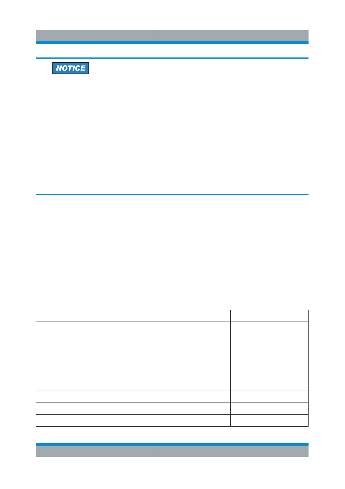
Power supply cable, delivered country-specific to fit your local wall outlet format, see Table 4-1
Table 4-1: Power cords
Power supply cables according to country-specific standards Order no.
European standard
Angular adapter for European standard
British standard 0006.7013.00
Swiss standard 0006.7020.00
US American standard 0006.7036.00
Australian standard 0006.7107.00
0025.2365.00
0086.4400.44
Chinese standard 0041.4752.00
Japanese standard 0041.6232.00
Brazilian standard 3587.8102.00
14Getting Started 1178.7117.02 ─ 03
Page 15

R&S®OSP
Placing or Mounting the Instrument
Preparing for Use
4.3 Placing or Mounting the Instrument
The R&S OSP is designed for use either on a bench top or in a standard 19"
rack.
Bench-top positioning
If the R&S OSP is operated on a bench top, the surface must be flat.
Risk of injury when stacking instruments
A stack of instruments can tilt over and cause injury if not stacked correctly.
Furthermore, the instruments at the bottom of the stack can be damaged
due to the load imposed by the instruments on top.
Observe the following instructions when stacking instruments:
●
Never stack more than three instruments. If you need to stack more
than three instruments, install them in a rack.
●
The overall load imposed on the lowest instrument must not exceed
500 N.
●
It is best if all instruments have the same dimensions (width and length).
If you need to stack smaller instruments on the top, the overall load
imposed on the lowest instrument must not exceed 250 N.
●
If the instruments have foldable feet, fold them in completely.
You can use the instrument in horizontal position, standing on its feet, or with the
support feet folded out from underneath.
15Getting Started 1178.7117.02 ─ 03
Page 16

R&S®OSP
Preparing for Use
Placing or Mounting the Instrument
Risk of injury if feet are folded out
The feet can fold in if they are not folded out completely or if the instrument
is shifted, which can cause damage or injury.
●
Fold the feet completely in or out to ensure stability of the instrument.
Never shift the instrument when the feet are folded out.
●
When the feet are folded out, do not work under the instrument or place
anything underneath.
●
The feet can break if they are overloaded. The overall load on the folded-out feet must not exceed 500 N.
F
max
Rack mounting
You can install the R&S OSP in a 19'' rack, using one of the following optional
rack adapter kits:
●
For 2 HU (R&S OSP220 and R&S OSP230), use R&S ZZA-211 (order no.
1096.3260.00)
●
For 3 HU (R&S OSP320), use R&S ZZA-311 (order no. 1096.3277.00)
The installation instructions for the adapter kit are included in its delivery.
The satellite unit R&S OSP-B200S2 is not designed for rack-mounting.
Risk of instrument damage due to insufficient airflow in a rack
If you mount several instruments in a rack, you need an efficient ventilation
concept to ensure that the instruments do not overheat. Insufficient airflow
for a longer period can disturb the operation and even cause damage.
16Getting Started 1178.7117.02 ─ 03
Page 17

R&S®OSP
Switching the Instrument On and Off
Preparing for Use
4.4 Connecting AC Power
The switch unit is equipped with an AC power supply connector and can be used
with different AC voltages. The R&S OSP adapts itself automatically to the voltage. Refer to the data sheet for the voltage and frequency requirements. The AC
power connector is on the rear panel of the instrument.
► Connect the R&S OSP to an AC power supply using the supplied power
cable.
As the instrument's assembly is in line with the specifications for safety class
EN61010, you must connect it only to an outlet that has a ground contact.
For replacing the fuses, refer to the maintenance chapter in the User Manual.
4.5 Switching the Instrument On and Off
Switching on
► Set the AC power switch on the rear panel to position "I".
The instrument is supplied with AC power. After booting, the instrument is
ready for operation. A green LED above the [Pwr] key on the front panel indicates the operating mode.
Switching off
1. If the LED above the [Pwr] key on the front panel emits green light, set the
R&S OSP to standby mode by pressing the [Pwr] key.
The LED changes from green to orange light, indicating sleep mode. The
switch unit is now unavailable via LAN, even if connected.
Otherwise, if the R&S OSP is already in standby mode, do not press the [Pwr]
key.
2. Set the AC power switch on the rear panel to position "O".
The R&S OSP changes into off mode.
17Getting Started 1178.7117.02 ─ 03
Page 18

R&S®OSP
Switching the Instrument On and Off
Display timeout
The OLED mini display of a switch unit R&S OSP220 or R&S OSP320
serves for showing you the network connection. It is switched off automatically, 30 minutes after specifying this LAN connection. Setting or changing
the LAN connection typically happens at power-up. Without a network connection, the OLED mini display is switched off 30 minutes after power-up.
This feature helps to prevent burn-in effects often seen in OLED displays.
When the switch unit is connected via a new network address, the mini display is switched on again for the next 30 minutes. (Your server can assign a
new network address, for example, when you change the switch unit's network settings from static IP to DHCP, as described in the User Manual.)
The RGB-LED touchscreen display in the R&S OSP230 and in the module R&S OSP-B300M needs no burn-in protection. Thus, it has no timeout.
Preparing for Use
Risk of losing settings
While the R&S OSP is in operating mode, if you switch it off using the rear
panel switch or by disconnecting the power cord, the instrument loses its
current settings. (Operating mode is indicated by a green LED above the
[Pwr] key.)
For example, if you have selected signal paths previously, you must select
and enable these paths again, when you restart the switch unit.
To avoid a loss of settings, press the [Pwr] key first to set the switch unit
into standby mode. Then shut it down properly by setting the rear AC power
switch to position "O".
●
If "Configuration" > "General" > "Switch-On Reset" is activated, the
R&S OSP resets all internal latching switches during the startup procedure.
●
If "Configuration" > "General" > "Switch-On Action" is set to "Switch
Path", the R&S OSP loads the previously set path while booting. The
switch unit then activates this path when the startup procedure is completed.
Configuring a master-slave setup of switch units is described in the User Manual.
18Getting Started 1178.7117.02 ─ 03
Page 19

R&S®OSP
Configuring the Initial Instrument Settings
Preparing for Use
4.6 Checking the Installed Modules
The instrument is typically equipped with one or more optional switch modules.
You can visually check whether the modules listed on your delivery note correspond with the installed modules. Each module's name is printed on its panel.
You can also view the installed modules in the "Module Operation" dialog (touchscreen display or "WebGUI", see Chapter 6.2, "User Interface
and Functional Elements", on page 31):
Figure 4-1: The module operation dialog, here with a master switch unit and 5 modules
The information in this dialog is updated during the booting process, when the
R&S OSP automatically detects the installed modules.
4.7 Configuring the Initial Instrument Settings
After startup, the switch unit is fully configured automatically, and ready for use.
However, you have many options to change the configuration, for example:
●
Edit the network settings
●
Define or modify a master-slave setup
●
Restore a previous setting
●
Define switching paths and output channels
These configuration settings and many more are described in the User Manual.
19Getting Started 1178.7117.02 ─ 03
Page 20

R&S®OSP
Instrument Tour
Front Panel View
5 Instrument Tour
5.1 Front Panel View
The following chapters describe the front panels of all models of the R&S OSP
switch unit family. For the functional elements, refer to Chapter 6.2.
5.1.1 Front Panel of the R&S OSP220........................................................... 20
5.1.2 Front Panel of the R&S OSP230........................................................... 21
5.1.3 Front Panel of the R&S OSP320........................................................... 21
5.1.4 Front Panel of the R&S OSP-B200S2 Satellite Unit.............................. 22
5.1.5 Touchscreen.......................................................................................... 23
5.1.1 Front Panel of the R&S OSP220
The front panel of the R&S OSP220 features 3 module slots, a monochrome nontouch mini display, a power switch and various connectors.
The R&S OSP220 occupies 2 height units (2HU) in a standard 19" rack. You can
insert 1-slot, 2-slot or 3-slot modules into the 3 front slots:
Figure 5-1: Front view of the R&S OSP220 (2HU)
FS01 = Front slot 01, here with a blind plate
FS02 = Front slot 02, here with a 1-slot switch module
FS03 = Front slot 03, here with a blind plate
F Int = Front interfaces and mini OLED display (128 x 64 pixels), see Figure 6-4
20Getting Started 1178.7117.02 ─ 03
Page 21

R&S®OSP
Instrument Tour
Front Panel View
5.1.2 Front Panel of the R&S OSP230
The front panel of the R&S OSP230 features 2 module slots, an integrated touchscreen display, a power switch and various connectors.
The R&S OSP230 occupies 2 height units (2HU) in a standard 19" rack. You can
insert two 1-slot modules or one 2-slot module into the 2 front slots:
Figure 5-2: Front view of the R&S OSP230 (2HU)
FS01 = Front slot 01, here with a blind plate
FS02 = Front slot 02, here with a 1-slot switch module
Disp. = Integrated touchscreen display
F Int = Front interfaces, see Figure 6-4
5.1.3 Front Panel of the R&S OSP320
The R&S OSP320 is higher than all other switch units from Rohde & Schwarz.
With its 3 height units (3HU), it enables a more dense fitting of 1-slot switch modules within the same instrument width. Hence, its front panel features 5 module
slots, along with a power switch, a mini display and various connectors.
2 of the 5 front slots (labeled FS04 and FS05 in Figure 5-3) can hold the factorymounted optional touchscreen display module R&S OSP-B300M:
21Getting Started 1178.7117.02 ─ 03
Page 22

R&S®OSP
Instrument Tour
Front Panel View
Figure 5-3: Front view of the R&S OSP320 (3HU)
FS01 = Front slot 01, here with a 1-slot switch module
FS02 = Front slot 02, here with a 1-slot switch module
FS03 = Front slot 03, here with a 1-slot switch module
FS04 + FS05 = Front slot 04 and 05, here with mounted touchscreen display module
F Int = Front interfaces and mini OLED display (128 x 64 pixels), see Figure 6-4
The dedicated touchscreen display module R&S OSP-B300M shown in Fig-
ure 5-3 is optional (see p. 23). It can only be factory-mounted in the
R&S OSP320 with 3 height units (3HU) in position FS04 + FS05.
You cannot insert any modules into the R&S OSP320 that are designed as 2-slot
or 3-slot modules for a switch unit with 2 height units (2HU, see above).
5.1.4 Front Panel of the R&S OSP-B200S2 Satellite Unit
For a comprehensive description of this unit, also refer to the R&S OSP-
B200R/B200S2 Satellite System User Manual, available for download at
www.rohde-schwarz.com/manual/osp.
The R&S OSP-B200S2 is a standalone device, only, not to be mounted into a 19"
rack. The front panel of satellite unit the features 2 module slots, into which you
can insert 1-slot or 2-slot modules:
22Getting Started 1178.7117.02 ─ 03
Page 23

R&S®OSP
Figure 5-4: Front view of the R&S OSP-B200S2 (2HU)
SlotA = Front slot A, here with a 1-slot switch module
SlotB = Front slot B, here with a 1-slot switch module
Instrument Tour
Front Panel View
This unit is designed to serve as a satellite with up to 2 switch modules, controlled
from a base switch unit with remote control module R&S OSP-B200R.
For example, you can use the satellite unit inside a shielded chamber for EMC
tests that do not tolerate electrical wiring. In this scenario, use the satellite with
local battery power supply, and control the switch modules fitted in the unit via a
fiber-optic link. See also Chapter 5.2.4.1, "Wired Link versus Fiber-Optic Link",
on page 28.
5.1.5 Touchscreen
Figure 5-5: Touchscreen display, here showing the Main menu
●
The R&S OSP230 is equipped with an integrated touchscreen display on the
front panel.
23Getting Started 1178.7117.02 ─ 03
Page 24

R&S®OSP
Instrument Tour
Front Panel View
●
The R&S OSP320 can be equipped with the touchscreen display module
R&S OSP-B300M.
Both the integrated display and the display module are based on a touch-sensitive RGB LCD with a resolution of 800 x 480 pixels.
The touchscreen display offers one out of several means of user interaction for
easily handling the switch unit. It shows the relay and switch-path settings, provides status information and allows configuring and controlling your measurement
tasks.
The touchscreen reacts in a defined way when you tap a particular
element on the screen with a finger or with a pointing device, for
example an external USB mouse. Any user interface element that
reacts to a click by a mouse pointer also reacts to a tap on the screen, and vice
versa. Using the touchscreen, you can perform all tasks by the tap of your finger.
For the remainder of this manual, all interactions are described for a "click" action.
These descriptions also mean the equivalent "tap" action using the touchscreen.
On-screen keyboard
The on-screen keyboard is an additional means of direct interaction with the
switch unit R&S OSP230 or R&S OSP320, the latter if equipped with touchscreen
module R&S OSP-B300M.
Figure 5-6: Different versions of the on-screen keyboard
Left = Numbers and characters allowed
Center = Decimal numbers, only
Right = Hexadecimal numbers
The touchscreen automatically opens an on-screen keyboard, if your current
action requires entering numbers or characters. The cancel button or the OK button closes the on-screen keyboard.
Instead of using the on-screen keyboard, you can enter data with a connected
external keyboard (Figure 6-1) or via the user interface in a browser (Figure 6-2).
24Getting Started 1178.7117.02 ─ 03
Page 25

R&S®OSP
Instrument Tour
Rear Panel View
5.2 Rear Panel View
The following chapters describe the rear panels of all models of the R&S OSP
switch unit family. For the functional elements, refer to Chapter 6.2.
5.2.1 Rear Panel of the R&S OSP220............................................................25
5.2.2 Rear Panel of the R&S OSP230............................................................25
5.2.3 Rear Panel of the R&S OSP320............................................................26
5.2.4 Rear Panel of the R&S OSP-B200S2 Satellite Unit...............................27
5.2.4.1 Wired Link versus Fiber-Optic Link........................................................28
5.2.1 Rear Panel of the R&S OSP220
The rear panel of the R&S OSP220 features 3 module slots, an on/off switch,
fuses, power supply connector, LAN and USB connectors and a micro SD card
slot. You can insert 1-slot, 2-slot or 3-slot modules into the 3 rear slots:
Figure 5-7: Rear view of the R&S OSP220 (2HU)
R Int = Rear interfaces, see Figure 6-4
RS01 = Rear slot 01, here with a blind plate
RS02 = Rear slot 02, here with a blind plate
RS03 = Rear slot 03, here with a blind plate
5.2.2 Rear Panel of the R&S OSP230
The rear panel of the R&S OSP230 features 3 module slots, an on/off switch,
fuses, power supply connector, LAN and USB connectors and a micro SD card
slot. You can insert 1-slot, 2-slot or 3-slot modules into the 3 rear slots:
25Getting Started 1178.7117.02 ─ 03
Page 26

R&S®OSP
Figure 5-8: Rear view of the R&S OSP230 (2HU)
R Int = Rear interfaces, see Figure 6-4
RS01 = Rear slot 01, here with a 1-slot switch module
RS02 = Rear slot 02, here with a 1-slot switch module
RS03 = Rear slot 03, here with a 1-slot switch module
5.2.3 Rear Panel of the R&S OSP320
Instrument Tour
Rear Panel View
The rear panel of the R&S OSP320 features 5 module slots, an on/off switch,
fuses, power supply connector, LAN and USB connectors and a micro SD card
slot:
Figure 5-9: Rear view of the R&S OSP320 (3HU)
R Int = Rear interfaces, see Figure 6-4, with an additional D-Sub 9 trigger connector
RS01 = Rear slot 01, here with a 1-slot switch module
RS02 = Rear slot 02, here with a 1-slot switch module
RS03 = Rear slot 03, here with a 1-slot switch module
RS04 = Rear slot 04, here with a 1-slot switch module
RS05 = Rear slot 05, here with a 1-slot switch module
You cannot insert any modules into the R&S OSP320 that are designed as 2-slot
or 3-slot modules for a switch unit with 2 height units (2HU, see above).
26Getting Started 1178.7117.02 ─ 03
Page 27

R&S®OSP
Instrument Tour
Rear Panel View
The D-Sub 9 trigger connector (next to the label "R Int" in Figure 5-9) is only
available in the rear interface panel of the R&S OSP320, not in any other
switch unit. However, triggering is not yet supported by the firmware. The
hardware trigger feature will be added as option R&S OSP-K100 in the
future.
5.2.4 Rear Panel of the R&S OSP-B200S2 Satellite Unit
For a comprehensive description of this unit, also refer to the R&S OSP-
B200R/B200S2 Satellite System User Manual, available for download at
www.rohde-schwarz.com/manual/osp.
The rear panel of the R&S OSP-B200S2 features various connectors and LEDs.
You cannot insert any modules into the rear panel of the R&S OSP-B200S2.
Figure 5-10: Rear view of the R&S OSP-B200S2 (2HU)
1 = DC power supply connector
2 = Fiber-optic link (FOL) connector for optical remote control
3 = Wired link connector for electrical remote control
4 = Status LEDs for indicating [Power] and [Overheat]
5 = Status LED for indicating [Link / Busy]
27Getting Started 1178.7117.02 ─ 03
Page 28

R&S®OSP
5.2.4.1 Wired Link versus Fiber-Optic Link
The link connectors (labeled (2) and (3) in Figure 5-10) allow choosing either an
electrical or an optical control connection.
●
Wired link
For remote operation of the satellite unit R&S OSP-B200S2 across distances
up to 10 m, use the D-Sub cable R&S OSP-Z200x.
Connect this cable exclusively to the remote control interface module
R&S OSP-B200R in your base switch unit. Connecting it to any other device
or module can harm your equipment.
The wired link cable supplies power from the base switch unit to the satellite.
●
Fiber-optic link
For remote operation of the satellite unit R&S OSP-B200S2 across larger distances up to 20 m, or inside a shielded room, use the fiber-optic cable
R&S OSP-Z201x or R&S OSP-Z202x.
As the fiber-optic link cable does not supply power to the satellite unit, you
must also use the 28 V DC power supply R&S OSP-B200P.
Instrument Tour
Rear Panel View
28Getting Started 1178.7117.02 ─ 03
Page 29

R&S®OSP
Manual and Remote Modes of Operation
Trying Out the Switch Unit
6 Trying Out the Switch Unit
This chapter introduces the most important basic operations and settings of the
R&S OSP step by step. For a complete overview, see the User Manual (p. 11).
Prerequisite: the instrument is set up, connected to mains power supply and started up, as described in Chapter 4 on page 13. The next sections describe:
● Manual and Remote Modes of Operation....................................................... 29
● User Interface and Functional Elements......................................................... 31
● Main Action Buttons........................................................................................ 34
● Elements of the Status Line............................................................................ 34
● Manual Module Operation...............................................................................35
6.1 Manual and Remote Modes of Operation
You can operate the switch unit by any of the following modes:
● Direct Manual Operation................................................................................. 29
● Manual Remote Operation.............................................................................. 30
● Remote Operation by SCPI Commands......................................................... 30
6.1.1 Direct Manual Operation
If you use an R&S OSP230 or an R&S OSP320 with display module R&S OSPB300M, you can control your switch unit by the user interface on the integrated
touchscreen display.
Alternatively, with any of the R&S OSP models, you can control your switch unit
via an external mouse and keyboard, connected to the USB interfaces (see (4) in
Figure 6-4). Optionally (especially without integrated touchscreen), you can con-
nect an external monitor to the switch unit's HDMI interface (see (5)).
Figure 6-1: Operation by integrated touchscreen (1) or by external USB / HDMI devices (2)
29Getting Started 1178.7117.02 ─ 03
Page 30

R&S®OSP
Trying Out the Switch Unit
Manual and Remote Modes of Operation
For connecting external devices, see Figure 6-4.
6.1.2 Manual Remote Operation
You can control one or more switch units by working with the user interface in a
web browser ("Web GUI") on a remote computer that is connected via LAN.
Figure 6-2: Manual remote operation via "WebGUI" and LAN
RJ45 = Ethernet (LAN) connector on the rear panel of each switch unit
Refer to the User Manual for more information, also regarding the combination of
several switch units in a master-slave setup.
Note that the legacy software R&S OSP Panel is not compatible with the
switch units R&S OSP220, R&S OSP230 and R&S OSP320.
6.1.3 Remote Operation by SCPI Commands
You can control the R&S OSP by SCPI commands sent from a remote computer
that is connected via LAN. Refer to the User Manual.
Figure 6-3: Remote operation by SCPI commands
RJ45 = Ethernet (LAN) connector on the rear panel of each switch unit
Far left = Two switch units integrated in a test system like R&S CEMS
30Getting Started 1178.7117.02 ─ 03
Page 31

R&S®OSP
Trying Out the Switch Unit
User Interface and Functional Elements
To do so, you have two options:
●
For SCPI command communication, use a terminal program like R&S Forum
or similar programming interface (for example with R&S VISA driver). Remote
operation and RC commands are described in the User Manual.
●
Let a test system software like R&S EMC32 or R&S ELEKTRA send the
required commands. Refer to www.rohde-schwarz.com/product/emc32 and
www.rohde-schwarz.com/product/elektra.
6.2 User Interface and Functional Elements
The switch units R&S OSP220 and
The switch unit R&S OSP230 and the display
module R&S OSP-B300M have a touch-
screen display.
Its functions are described in the User Manual.
R&S OSP320 have a micro display.
Use it to find the IP address in the first
2 lines and the subnet mask in the last
2 lines.
You cannot operate the switch units R&S OSP220 ‒ and the R&S OSP320 without display module R&S OSP-B300M ‒ by their micro displays. To operate these
switch units without the graphical user interface of a built-in full touchscreen display, use one of the following alternatives:
●
As on the right-hand side in Figure 6-1, connect an external monitor to the
HDMI connector on the unit's front panel (labeled (5) in Figure 6-4). Also connect a mouse and keyboard to the USB connectors, labeled (4).
●
Use the switch unit as a slave device in a master-slave setup, as described in
the User Manual.
●
Connect the switch unit to a local area network (LAN) by the RJ45 connector
on the unit's rear panel. The connector is labeled (1) in Figure 6-4. Read the
unit's IP address from the micro display and proceed as described in Chap-
ter 6.1.2, "Manual Remote Operation", on page 30, or Chapter 6.1.3, "Remote
Operation by SCPI Commands", on page 30.
31Getting Started 1178.7117.02 ─ 03
Page 32

R&S®OSP
Trying Out the Switch Unit
User Interface and Functional Elements
Figure 6-4: Connectors and functional elements on the switch unit's rear and front panel
R = Rear interfaces (where the R&S OSP320 has an additional trigger port, see Figure 5-9)
F = Front interfaces (where the R&S OSP220 has no OLED micro display)
I/0 = Main power switch with fuse holder and power connector
1 = LAN connector (RJ45)
2 = Slot for the micro SD card that holds the switch unit's operating system
3 = USB 3.1 connector
4 = Two USB 2.0 connectors (for external mouse and keyboard)
5 = HDMI connector (for an external monitor)
6 = Two BNC trigger input connectors (A and B) with two trigger status LEDs
7 = Front power switch with [Pwr] and LAN status LEDs
If you connect an external monitor to the HDMI connector (5), use a monitor
that is compatible with this port’s DVI signal, which has the touchscreen's
resolution of 800 x 480 pixels. Incompatible monitors cannot display the
graphical user interface.
The trigger connectors (6) are not yet supported by the firmware. The hardware trigger feature will be added as option R&S OSP-K100 in the future.
Note that the rear interface panel of the R&S OSP320 has an additional DSub 9 trigger connector, shown in Rear view of the R&S OSP320 (3HU) on
page 26.
In any of these configurations, you can operate a switch unit by its user interface:
either in a browser window or on an external monitor. The same holds true for the
R&S OSP230 and R&S OSP320 with integrated display module R&S OSPB300M, which provide touchscreen operation.
Using any of these options, you get access to the graphical user interface (GUI):
32Getting Started 1178.7117.02 ─ 03
Page 33

R&S®OSP
User Interface and Functional Elements
Figure 6-5: Main menu of the graphical user interface
In the "Main" menu of the user interface, clicking the "Help" icon in the
top right area opens an overview of the available functions:
Trying Out the Switch Unit
Figure 6-6: Main elements of the graphical user interface (GUI)
1 = Main menu
2 = Module operation
3 = Path switching
4 = Device configuration
5 = Context menu, always used together with one of the menu buttons above
6 = Status line with varying elements, see Chapter 6.4
The main GUI elements listed above are briefly described in Chapter 6.3, "Main
Action Buttons", on page 34, and Chapter 6.4, "Elements of the Status Line",
on page 34. For more information, refer to the User Manual.
33Getting Started 1178.7117.02 ─ 03
Page 34

R&S®OSP
Trying Out the Switch Unit
Elements of the Status Line
6.3 Main Action Buttons
The user interface includes the following main action buttons:
The "Main" menu provides status and network information. Its context
menu (1)+(5) gives additional device info and messages.
The "Module Operation" dialog allows immediate interaction with the
relays. For a brief overview, see Chapter 6.5.
The "Path Switching" dialog allows defining, editing and activating
paths. You can also export and import paths.
The "Configuration" dialog provides general settings, settings for network connectivity and for master/slave operation.
Context Menu
The "Context Menu" button calls specific functionality for any of the
menu items shown above and listed as (1) to (4) in Figure 6-6. Hence,
this button is always used together with one of the other buttons.
For more information, refer to the User Manual.
6.4 Elements of the Status Line
The status line is shown on top in Figure 6-5 and Figure 6-6. The various indicator icons have the following meanings:
Left: the R&S OSP is controlled by its graphical user interface
(locally or via LAN). Right: the R&S OSP is controlled
remotely by SCPI commands or a master. See Chapter 6.1,
"Manual and Remote Modes of Operation", on page 29.
If this label is displayed in the status line, the R&S OSP is in virtual
mode (see User Manual).
If the lock icon is highlighted (right), it indicates the locked mode (see
User Manual).
If the selection indicator icon is highlighted (right), at least one
relay or output channel is selected (see Chapter 6.5.2).
34Getting Started 1178.7117.02 ─ 03
Page 35

R&S®OSP
Trying Out the Switch Unit
Manual Module Operation
6.5 Manual Module Operation
This chapter outlines only the most basic features of the dialogs for manual "Module Operation" that allow immediate interaction with the relays.
Click to either see a list of all installed switch modules or to see the
interaction dialog of one switch module:
Table 6-1: List of installed modules (left), interaction dialog of one switch module (right)
If you see the interaction dialog of one switch module, click to see the list of
installed modules. Then click the name of any module to see its interaction dialog.
6.5.1 Switching Mode
As long as the selection mode (see Chapter 6.5.2) is deactivated, click the icon of
a relay or channel to change its state:
Figure 6-7: Various relay types and the effect of clicking them
●
(A) SPDT relays, and (B) DPDT relays: Clicking toggles the state
●
(C) SP6T relays, and (D) SP8T relays:
Clicking a terminal port selects it to be connected to the common port
●
(E) Output channels: Clicking toggles the state
35Getting Started 1178.7117.02 ─ 03
Page 36

R&S®OSP
Trying Out the Switch Unit
Manual Module Operation
For switching relays and output channels, the "Toggle select mode" button
(orange, described below) must not be active.
6.5.2 Selection Mode
The "Toggle select mode" button switches the "Selection Mode" on or off. This
button (marked by a red circle in Figure 6-8) is only available in a view that shows
at least one module and its details.
Figure 6-8: Relay or channel selection dialog
Red circle = "Toggle select mode" button. If the button is orange, the "Selection Mode" is
activated.
Green circle = "Items selected" indicator. The icon is highlighted, if at least one relay or output
channel in any module is selected.
Orange frames = Selected relays and output channels are highlighted in the module's interaction
dialog
While the "Selection Mode" is active, tapping or clicking the icon of a relay or output channel does not change its state, but only selects or deselects the relay
or channel. This selection is indicated by the color of the icon's frame changing
from gray to orange.
Use the selection mode for defining paths and output patterns.
To select or deselect all relays and output channels, go to "Module Operation" (or "Path Switching") > "Context Menu" > "Path Selection" > "Select
All" or "Deselect All".
36Getting Started 1178.7117.02 ─ 03
Page 37

R&S®OSP
Trying Out the Switch Unit
Manual Module Operation
In a full-screen window of your web browser, the module interaction dialog
can display several modules at the same time:
Figure 6-9: Full-screen representation of several modules in a browser window
On the contrary, to reproduce the original size of the touchscreen display,
set your browser window to 800 × 480 pixels. Optionally, hit [F12] to enter
this setting.
For a comprehensive description of module operation and all other functions,
including the definition and switching of paths, refer to the User Manual.
37Getting Started 1178.7117.02 ─ 03
 Loading...