

Page 1
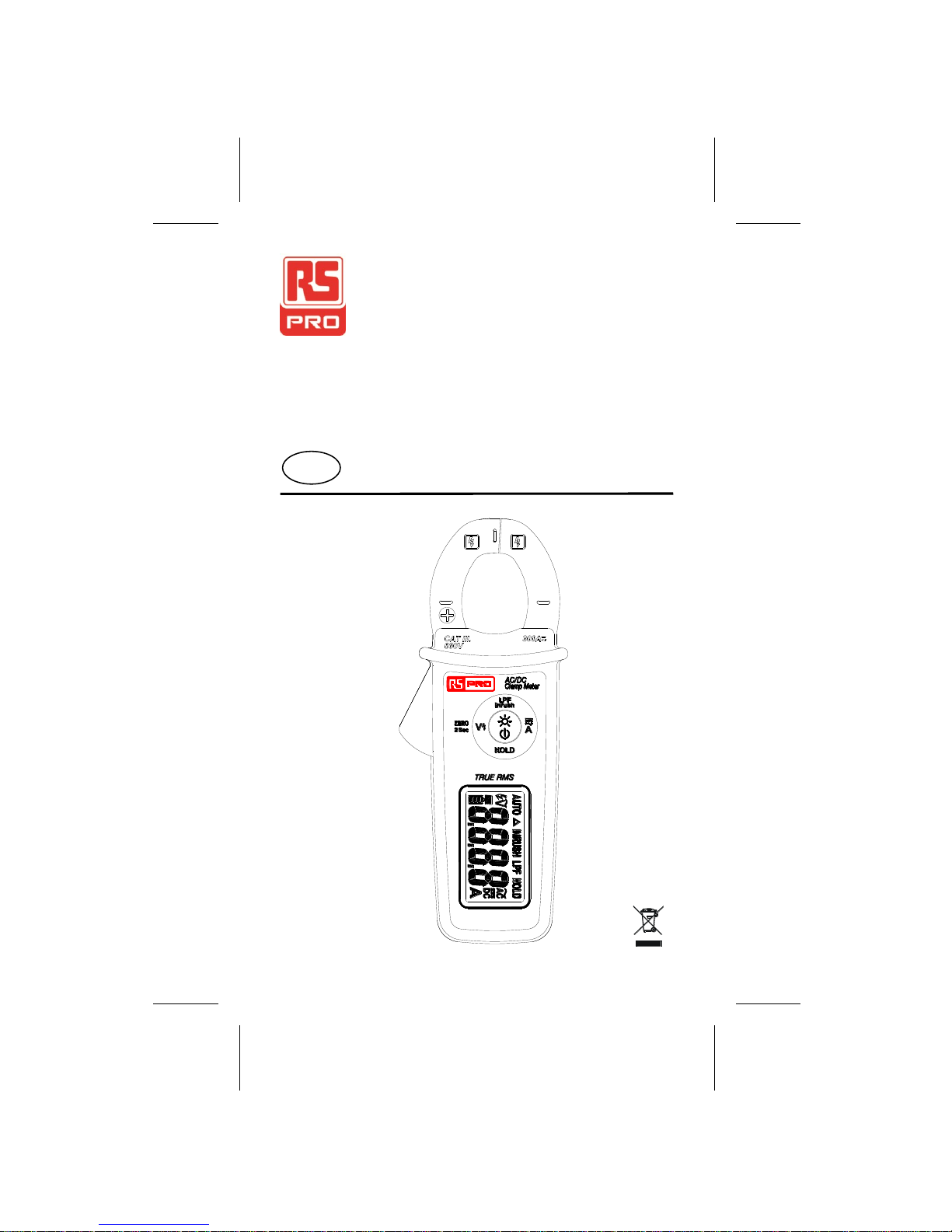
Instruction Manual
ICM A1
AC/DC Clamp Meter
EN
ICM A1
Page 2
1
Warning
. . . . . . . . . .
. . . . . . . . . .
. . . . . . . . . .
. . . . . . . .
Safety sheet
. . . . . . . . .
. . . . . . . . . .
. . . . . . . . . .
. . . . . . . .
. . . . . . . . .
Read First
Safety Information
- Use the instrument only as specified in this
manual or the protection by the instrument
might be impaired.
- Always use proper terminals, switch position,
and range for measurements.
- Verify the instrument’s operation by measure
ing a known voltage. If in doubt, have the
instrument serviced.
- Do not apply more than the rated voltage,
as marked on the instrument.
- To avoid false readings that can lead to
electric shock and injury, replace battery as
soon as low battery indicator.
- Do not use the instrument around explosive
gas or vapor.
- To reduce the risk of fire or electric shock
do not expose the instrument to rain or
moisture.
- Individual protective equipment should be
used if HAZARDOUS LIVE parts in the
installation where measurement is to be
carried out could be ACCESSIBLE.
- Do not allow fingers to protrude beyond
the Tactile Barrier when fitting or removing
the instrument from around a Hazardous
Live conductor, as this may cause a shock.
Page 3
2
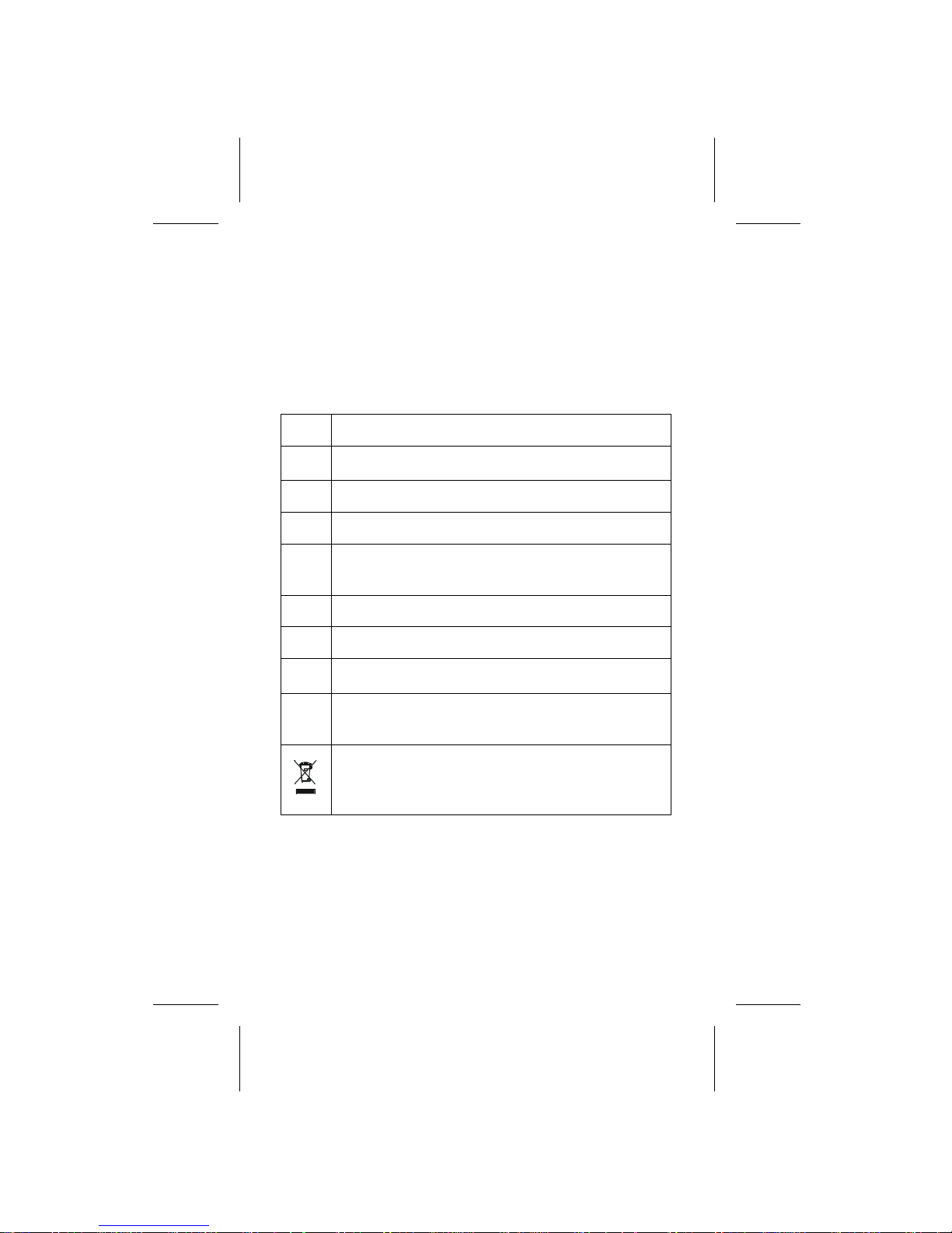
Risk of electric shock
See instruction card
DC measurement
AC measurement
Equipment protected by double or
reinforced insulation
<
Battery
Earth
Conforms to EU directives
E
Application around and removal from
hazardous live conductors is permitted
Do not dispose this electrical or
electronic product in domestic household
waste.
Caution
Do not expose the instrument to extremes in
temperature or high humidity.
Symbols as marked on the instrument
and instruction manual
Page 4
3
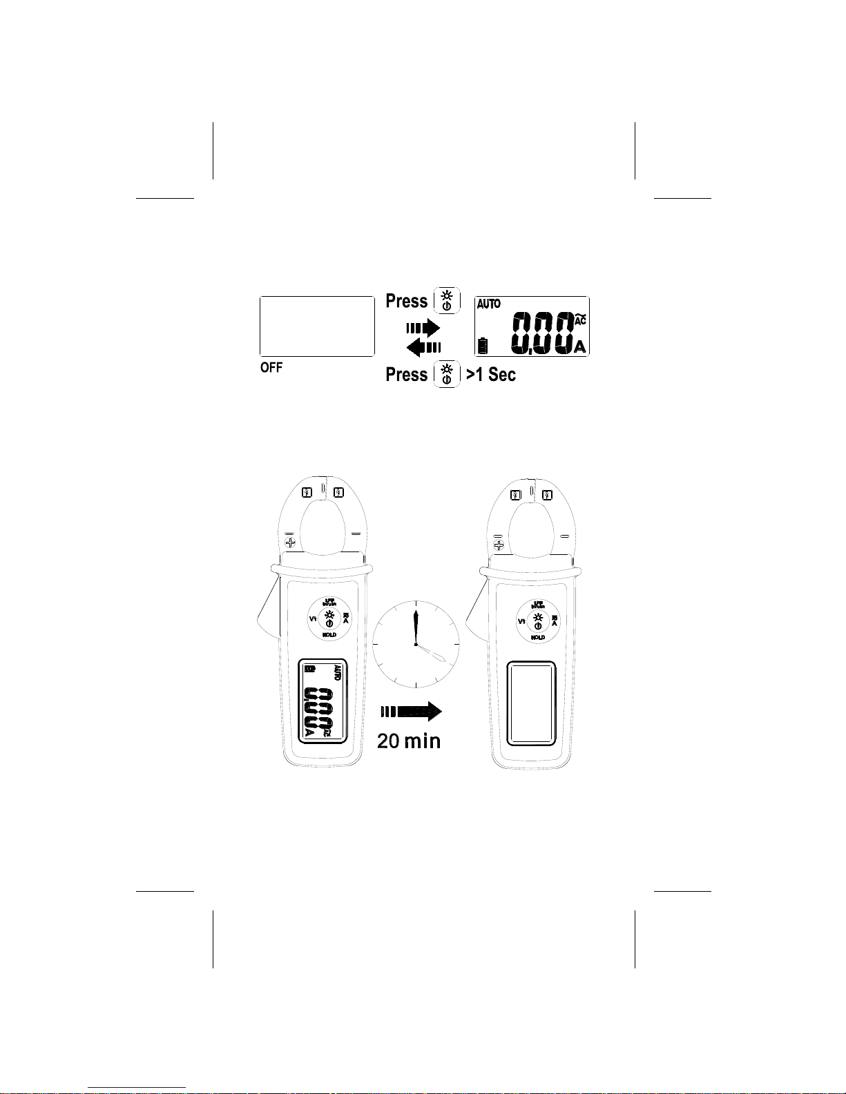
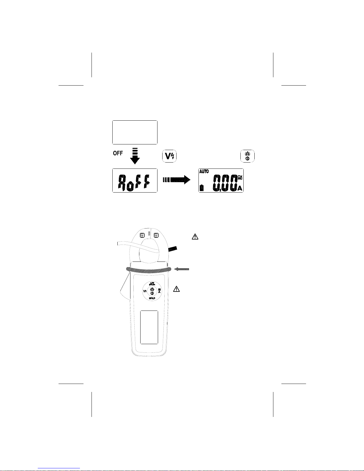
Power on / off
Auto Power Off
Page 5
4
Auto Power Off Disable
Hold down and press
ACA & DCA
Barrier for
Hand Guard
earth for the jaw
with respect to
The barrier on the JAW
safe access of the handheld part, do not hold
in normal use.
over the barrier when
is indicating the limit of
CAT.Ⅲ600V
Page 6
5
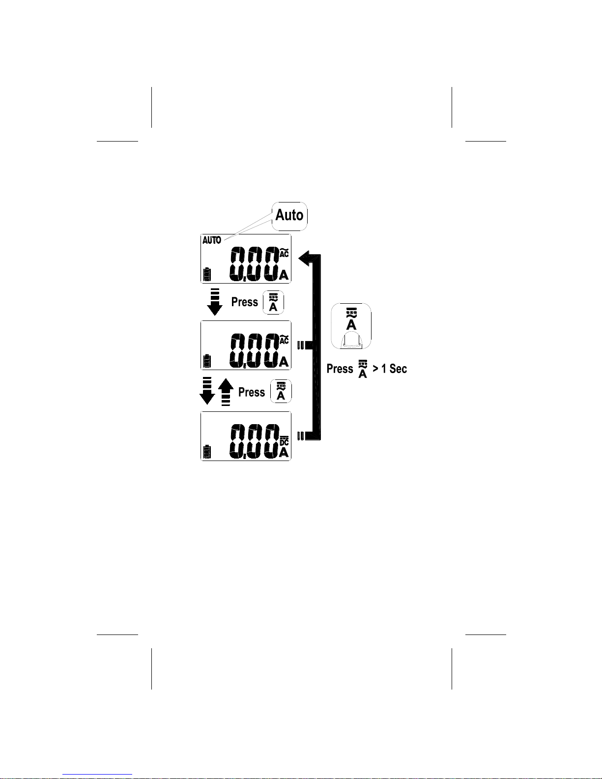
Auto ACA&DCA Detection / ACA&DCA
Due to the high sensitivity of the instrument,
perform DCA Zero in the same direction as
measurement to avoid interference by an
external magnetic field.
Page 7

6
Data Hold
The display will flash continuously if the measured
signal is larger by 50counts than the display
reading. However, it cannot detect across the AC
and DC Current.
Page 8

7
The instrument calculates the RMS value for
100ms as detecting a more than 5A current.
DCA ZERO
Inrush Current
Page 9

8
Low Pass Filter
The cut -off frequency of the low pass filter is
about 160Hz with attenuation characteristic of
approx-24db/octave.
Backlight on/off
Page 10

9
Voltsense
The number of dashes displaying on the LCD
indicates the electric field intensity.
If no indication, voltage could still be present.
Page 11

10
Battery Replacement
Maintenance
Do not attempt to repair this instrument.
It contains no user-serviceable parts. Repair
or servicing should only be performed by
qualified personnel.
Cleaning
Periodically wipe the case with a dry cloth and
detergent. Do not use abrasives or solvents.
Page 12

11
Specifications
1-1 General Specifications
Display Count : 6000 count
Overrange Display : “OL” or “-OL”
Conversion Rate : 2 times / second
Dimensions (W x H x D) : 60 x 147 x 31.5 mm
Weight : 140 g
Power requirement :
LR44 Size Button Battery 1.5V x 2
Battery Life : 20 hours.
Maximum Conductor Size : 22 diameter
LVD : EN61010-1, EN61010-2-030,
EN61010-2-032
EMC : EN61326-1
Installation category : CAT.Ⅲ. 600V.
CAT. Application field
Ⅰ
The circuits is not connected to mains.
Ⅱ
The circuits is directly connected to
Low-voltage installation.
Ⅲ
The building installation.
Ⅳ
The source of the Low-voltage installation.
Page 13

12
1-2 Environmental Conditions
Indoor Use.
Maximum operating altitude :
2000m (6562 ft)
Operating temperature :
0°C ~ 30°C, ≦80%RH
30°C ~ 40°C, ≦75%RH
40°C ~ 50°C, ≦45%RH
Storage temperature :
-20 to +60°C, 0 to 80% RH (no batteries).
Temperature coefficient :
0.2 x (Specified accuracy) / °C, < 18°C, > 28°C
Pollution Degree : 2
Shock vibration :
MIL-PRF-28800F for A class 2 Instrument
Drop Protection :
4 Feet Drop to hardwood on concrete Floor
Page 14

13
1-3 Electrical Specifications
Accuracy is given as ±(% of reading + counts
of least significant digit) at 23°C ± 5°C,with
relative humidity Less than 80% R.H.
ACV and ACA specifications are ac coupled,
true R.M.S. The crest factor may be up to 3.0
as 4000 counts.
For non-sinusoidal waveforms, Additional
Accuracy by Crest Factor (C.F.) :
Add 3.0% for C.F. 1.0 ~ 2.0.
Add 5.0% for C.F. 2.0 ~ 2.5.
Add 7.0% for C.F. 2.5 ~ 3.0.
Position Error of Clamp: ±1.5% of LCD reading.
DC Current
Range Resolution Accuracy
60.00A
(1)
0.01A ±(1.5% +10D)
(2)
300.0A 0.1A ±(1.5% + 5D)
All specifications are valid from 5% to 100%
of each range.
(1) There is less than 0.3A variation as
measuring in different directions.
(2) Add 10D to accuracy in Auto AC & DC
Sense Mode.
Page 15

14
AC Current
Range Resolution
Accuracy
(50 ~ 100Hz)
Accuracy
(100 ~ 400Hz)
60.00A 0.01A
±(1.5% + 5D) ±(2.5% +5D)
300.0A 0.1A
All specifications are valid from 5% to 100% of
each range.
Frequency Response : 50 ~ 400Hz
(Sine Wave)
Low-pass Filter
Range Resolution
Accuracy
(50Hz/60Hz)
60.00A 0.01A ±(3.5%+5D)
300.0A 0.1A ±(3.5%+5D)
All specifications are valid from 5% to 100%
of each range.
Cut-off Frequency (-3dB) : Approx. 160Hz
Attenuation Characteristic :
Approx. -24dB / Oct
Page 16

15
Inrush Current
Range Resolution
300.0A 0.1A
Integration Time : 100ms
Trigger Current : 5.0A
VoltSense
Voltage Range : 80V ~ 600V
(At the tip of clamp)
Page 17

16
Limited Warranty
This meter is warranted to the original
purchaser against defects in material and
workmanship for 3 years from the date of
purchase. During this warranty period,
RS Components will, at its option, replace or
repair the defective unit, subject to verification
of the defect or malfunction.
This warranty does not cover fuses,
disposable batteries, or damage from abuse,
neglect, accident, unauthorized repair,
alteration, contamination, or abnormal
conditions of operation or handling.
Any implied warranties arising out of the sale
of this product, including but not limited to
implied warranties of merchantability and
fitness for a particular purpose, are limited
to the above. RS Components shall not be
liable for loss of use of the instrument or
Other incidental or consequential damages,
expenses, or economic loss, or for any claim
or claims for such damage, expense or
economic loss. Some states or countries laws
vary, so the above limitations or exclusions
may not apply to you. For full terms and
conditions, refer to the RS website.
Page 18

Africa
RS Components SA
P.O. Box 12182, Vorna Valley, 1686
20 Indianapolis Street, Kyalami Business Park,
Kyalami, Midrand, South Africa
www.rs-components.com
Asia
RS Components Pte Ltd.
31 Tech Park Crescent
Singapore 638040
www.rs-components.com
China
RS Components Ltd.
Suite 23 A-C , East Sea Business Centre
Phase 2 , No. 618 Yan'an Eastern Road
Shanghai, 200001, China
www.rs-components.com
Europe
RS Components Ltd.
PO Box 99, Corby,
Northants. NN17 9RS, United Kingdom
www.rs-components.com
Japan
RS Components Ltd.
West Tower (12th Floor),
Yokohama Business Park, 134 Godocho,
Hodogaya, Yokohama, Kanagawa 240-0005,
Japan
www.rs-components.com
U.S.A
Allied Electronics
7151 Jack Newell Blvd. S.
Fort Worth, Texas 76118 , U.S.A.
www.alliedelec.com
South America
RS Componentes Limitada
Av. Pdte. Eduardo Frei M. 6001-71
Centro Empresas El Cortijo
Conchali, Santiago, Chile
www.rs-components.com
 Loading...