

Page 1

R&S®FSH
Handheld
Spectrum Analyzer
Quick Start
Page 2

Rohde & Schwarz
GmbH & Co. KG
Mühldorfstraße 15
81671 München, Germany
www.rohde-schwarz.com
Customer Support
Europe, Africa, Middle East
Phone +49 (18 05) 12 42 42
or +49 (89) 41 29-137 74
customersupport@
rohde-schwarz.com
North America
Phone 1-888-837-87 72
customer.support@
rsa.rohde-schwarz.com
Latin America
Phone +1-410-910-79 88
customersupport.la@
rohde-schwarz.com
Asia/Pacifi c
Phone +65 65 13 04 88
customersupport.asia@
rohde-schwarz.com
Order No.: 1309.6269.62-14
This fi rmware makes use of several valuable
open source software packages. A detailed list
of the used open source software is provided
on the user documentation CD-ROM (included
in delivery).
The verbatim license texts are provided on
the user documentation CD-ROM (included in
delivery).
Rohde & Schwarz would like to thank the open
source community for their valuable contribution
to embedded computing. The source code of the
open source packages is available on request.
© 2008 Rohde & Schwarz GmbH & Co. KG
Printed in Netherlands
R&S® is a registered trademark of Rohde &
Schwarz GmbH & Co. KG.
Trade names are trademarks of the owners.
The following abbreviations are used throughout
this manual:
R&S®FSH is abbreviated as R&S FSH.
Page 3

Contents
Safety Instructions . . . . . . . . . . . . . . . . . . . . . . . . . . . . . . 3
Informaciones Elementales de Seguridad . . . . . 13
1 Hints . . . . . . . . . . . . . . . . . . . . . . . . . . . . . . . . . . . . . . .24
1.1 Certifi cate of quality . . . . . . . . . . . . . . . . . . . . . . . . . . 24
1.2 Support Center . . . . . . . . . . . . . . . . . . . . . . . . . . . . . . 25
2 Putting into Operation . . . . . . . . . . . . . . . . . . . . .26
2.1 Front view . . . . . . . . . . . . . . . . . . . . . . . . . . . . . . . . . .26
2.2 Putting into Operation . . . . . . . . . . . . . . . . . . . . . . . . 28
2.2.1 Unpacking the Instrument . . . . . . . . . . . . . . . . . . . .28
2.2.2 Setting up the Instrument . . . . . . . . . . . . . . . . . . . .30
2.2.3 Switching on the Spectrum Analyzer . . . . . . . . . . .31
2.2.4 Charging the Battery . . . . . . . . . . . . . . . . . . . . . . . .34
2.2.5 Spectrum Analyzer Connectors . . . . . . . . . . . . . . . . 38
2.2.6 Hardware Settings . . . . . . . . . . . . . . . . . . . . . . . . . . 45
2.2.7 Screen Settings . . . . . . . . . . . . . . . . . . . . . . . . . . . .46
2.2.8 Audio Settings . . . . . . . . . . . . . . . . . . . . . . . . . . . . .48
2.2.9 Regional Settings . . . . . . . . . . . . . . . . . . . . . . . . . .50
2.2.10 Setting the Date and Time . . . . . . . . . . . . . . . . . . . . 51
2.3 Self Alignment . . . . . . . . . . . . . . . . . . . . . . . . . . . . . . .53
2.4 Setting the Instrument Default Setup . . . . . . . . . . . .54
2.4.1 Setting Preset . . . . . . . . . . . . . . . . . . . . . . . . . . . . . 54
2.4.2 Reset to Factory Settings . . . . . . . . . . . . . . . . . . . . 55
2.5 Selecting External Reference / External Trigger /
Direct Current Input (BIAS Port 2) . . . . . . . . . . . . . . . 56
2.6 Selecting the Intermediate Frequency Output (IF Out)
/ Direct Current Input (BIAS Port 1) . . . . . . . . . . . . . . 57
2.7 Enabling Options . . . . . . . . . . . . . . . . . . . . . . . . . . . . 59
2.8 Checking the Installed Options . . . . . . . . . . . . . . . . . 60
2.9 Setting up a LAN or USB Connection to a PC . . . . . . 61
2.9.1 Direct connection via LAN . . . . . . . . . . . . . . . . . . . . 61
2.9.2 Connection via an existing LAN network . . . . . . . .65
2.9.3 Connection via USB . . . . . . . . . . . . . . . . . . . . . . . . 67
1
E-02
Page 4

3 Getting started . . . . . . . . . . . . . . . . . . . . . . . . . . . . 71
3.1 Controlling the RF Attenuator . . . . . . . . . . . . . . . . . . 71
3.2 Using a Preamplifi er . . . . . . . . . . . . . . . . . . . . . . . . . . 75
3.3 Measurements on CW Signals . . . . . . . . . . . . . . . . .77
3.3.1 Level Measurement . . . . . . . . . . . . . . . . . . . . . . . .77
3.3.2 Setting the Reference Level . . . . . . . . . . . . . . . . . . 80
3.3.3 Frequency Measurements . . . . . . . . . . . . . . . . . . . 81
3.3.4 Harmonic Measurements of a Sinewave Signal . . . 83
2
3.4 Power Measurements Using the Power Sensor . . . . 85
3.5 Power and Return Loss Measurements with the
R&S FSH-Z14 or the R&S FSH-Z44 . . . . . . . . . . . . . . 90
3.6 Measurement of the Transfer Function of Two-Port
Networks . . . . . . . . . . . . . . . . . . . . . . . . . . . . . . . . . . . 94
3.6.1 Calibrating the R&S FSH for Vector Measurement of
the Transmission Function . . . . . . . . . . . . . . . . . . . . 95
3.6.2 Calibrating the R&S FSH for Scalar Measurement of
the Transmission Function . . . . . . . . . . . . . . . . . . . . 96
3.6.3 Measure the magnitude of the transfer function. . .98
3.7 Return Loss Measurement . . . . . . . . . . . . . . . . . . . 100
3.7.1 Calibrate the R&S FSH for the Vector Return Loss
Measurement . . . . . . . . . . . . . . . . . . . . . . . . . . . . 102
3.7.2 Calibrate the R&S FSH for the Scalar Return Loss
Measurement . . . . . . . . . . . . . . . . . . . . . . . . . . . . 104
3.7.3 Restore Calibration Settings . . . . . . . . . . . . . . . . . 106
3.7.4 Using the Factory Calibration . . . . . . . . . . . . . . . . 107
3.8 Measuring Cable Faults . . . . . . . . . . . . . . . . . . . . . . 108
3.9 Saving and Recalling Settings and Test Results . . . 115
3.9.1 Saving Measurement Results . . . . . . . . . . . . . . . . 116
3.9.2 Recalling Measurement Results . . . . . . . . . . . . . . 119
3.10 GPS Information Display . . . . . . . . . . . . . . . . . . . . . 120
Index . . . . . . . . . . . . . . . . . . . . . . . . . . . . . . . . . . . . . . . . . . . 123
PD 1309.6269.62-02
Page 5

Safety Instructions
Make sure to read through and observe the
following safety instructions!
All plants and locations of the Rohde & Schwarz
group of companies make every effort to keep the
safety standard of our products up to date and to
offer our customers the highest possible degree of
safety. Our products and the auxiliary equipment
required for them are designed and tested in
accordance with the relevant safety standards.
Compliance with these standards is continuously
monitored by our quality assurance system.
The product described here has been designed
and tested in accordance with the EC Certifi cate
3
of Conformity and has left the manufacturer’s
plant in a condition fully complying with safety
standards. To maintain this condition and to
ensure safe operation, observe all instructions
and warnings provided in this manual. If you have
any questions regarding these safety instructions,
the Rohde & Schwarz group of companies will be
happy to answer them.
Furthermore, it is your responsibility to use the
product in an appropriate manner. This product is
designed for use solely in industrial and laboratory
environments or, if expressly permitted, also in the
fi eld and must not be used in any way that may
cause personal injury or property damage. You are
responsible if the product is used for an intention
other than its designated purpose or in disregard of
the manufacturer’s instructions. The manufacturer
shall assume no responsibility for such use of the
product.The product is used for its designated
purpose if it is used in accordance with its product
documentation and within its performance limits
(see data sheet, documentation, the following
E-02
Page 6

safety instructions). Using the product requires
technical skills and a basic knowledge of English.
It is therefore essential that only skilled and
specialized staff or thoroughly trained personnel
with the required skills be allowed to use the
product. If personal safety gear is required for
using Rohde & Schwarz products, this will be
indicated at the appropriate place in the product
4
documentation. Keep the basic safety instructions
and the product documentation in a safe place and
pass them on to the subsequent users.
Symbols and safety labels:
Observe product documentation
PE terminal
Ground terminal
Danger of electric shock
Warning! Hot surfaces
Ground
Attention! Electrostatic sensitive
devices
PD 1309.6269.62-02
Page 7

Observing the safety instructions will help prevent
personal injury or damage of any kind caused
by dangerous situations. Therefore, carefully
read through and adhere to the following safety
instructions before putting the product into
operation. It is also absolutely essential to observe
the additional safety instructions on personal
safety that appear in relevant parts of the product
documentation. In these safety instructions, the
word “product” refers to all merchandise sold
and distributed by the Rohde & Schwarz group of
companies, including instruments, systems and all
accessories.
Tags and their meaning
DANGER DANGER indicates a hazardous
situation which, if not avoided, will
5
result in death or serious injury.
WARNING WARNING indicates a hazardous
situation which, if not avoided, could
result in death or serious injury.
CAUTION CAUTION indicates a hazardous
situation which, if not avoided, may
result in minor or moderate injury.
NOTICE NOTICE indicates a property damage
message.
In the product documentation,
the word ATTENTION is used
synonymously.
These tags are in accordance with the standard
defi nition for civil applications in the European
Economic Area. Defi nitions that deviate from
the standard defi nition may also exist in other
economic areas or military applications. It is
therefore essential to make sure that the tags
E-02
Page 8

described here are always used only in connection
with the related product documentation and the
related product. The use of tags in connection with
unrelated products or documentation can result in
misinterpretation and thus contribute to personal
injury or material damage.
Basic safety instructions
6
The product may be operated only under the 1.
operating conditions and in the positions
specifi ed by the manufacturer. The R&S FSH
is protected against dripping water and dust
(IP degree 51). Unless otherwise specifi ed,
the following requirements apply to Rohde
& Schwarz products: prescribed operating
position is always with the housing fl oor facing
down, IP protection 2X, pollution severity 2,
overvoltage category 2, use only in enclosed
spaces, max. operation altitude 4600 m above
sea level, max. transport altitude 12000 m
above sea level. A tolerance of ±10% shall
apply to the nominal voltage and of ±5% to the
nominal frequency.
Applicable local or national safety regulations 2.
and rules for the prevention of accidents must
be observed in all work performed. The product
may be opened only by authorized, specially
trained personnel. Prior to performing any work
on the product or opening the product, the
product must be disconnected from the supply
network. Any adjustments, replacements of
parts, maintenance or repair must be carried
out only by technical personnel authorized
by Rohde & Schwarz. Only original parts may
PD 1309.6269.62-02
Page 9

be used for replacing parts relevant to safety
(e.g. power switches, power transformers,
fuses, batteries). A safety test must always be
performed after parts relevant to safety have
been replaced (visual inspection, PE conductor
test, insulation resistance measurement,
leakage current measurement, functional test).
As with all industrially manufactured goods, 3.
the use of substances that induce an allergic
reaction (allergens, e.g. nickel) such as
aluminum cannot be generally excluded. If you
develop an allergic reaction (such as a skin
rash, frequent sneezing, red eyes or respiratory
diffi culties), consult a physician immediately to
determine the cause.
If products/components are mechanically and/4.
or thermically processed in a manner that
goes beyond their intended use, hazardous
substances (heavy-metal dust such as lead,
beryllium, nickel) may be released. For this
reason, the product may only be disassembled,
e.g. for disposal purposes, by specially trained
personnel. Improper disassembly may be
7
hazardous to your health. National waste
disposal regulations must be observed.
Depending on the function, certain products 5.
such as RF radio equipment can produce an
elevated level of electromagnetic radiation.
Considering that unborn life requires increased
protection, pregnant women should be
protected by appropriate measures. Persons
with pacemakers may also be endangered
E-02
Page 10

by electromagnetic radiation. The employer/
operator is required to assess workplaces
where there is a special risk of exposure to
radiation and, if necessary, take measures to
avert the danger.
Operating the products requires special 6.
training and intense concentration. Make
8
certain that persons who use the products are
physically, mentally and emotionally fi t enough
to handle operating the products; otherwise
injuries or material damage may occur. It is the
responsibility of the employer to select suitable
personnel for operating the products.
Prior to switching on the product, it must be 7.
ensured that the nominal voltage setting on the
power supply matches the nominal voltage of
the AC supply network.
If the product has no power switch for 8.
disconnection from the AC supply, the plug
of the connecting cable is regarded as the
disconnecting device. In such cases, it must be
ensured that the power plug is easily reachable
and accessible at all times (corresponding
to the length of connecting cable, approx. 2
m). Functional or electronic switches are not
suitable for providing disconnection from
the AC supply. If products without power
switches are integrated in racks or systems, a
disconnecting device must be provided at the
system level.
PD 1309.6269.62-02
Page 11

Never use the product if the power cable is 9.
damaged. Check the power cable on a regular
basis to ensure that it is in proper operating
condition. By taking appropriate safety
measures and carefully laying the power cable,
ensure that the cable cannot be damaged and
that no one can be hurt by e.g. tripping over the
cable or suffering an electric shock.
The product may be operated only from TN/TT 10.
supply networks fused with max. 16 A (higher
fuse only after consulting with the Rohde &
Schwarz group of companies).
Do not insert the plug into sockets that are 11.
dusty or dirty. Insert the plug fi rmly and all the
way into the socket. Otherwise, this can result
9
in sparks, fi re and/or injuries.
Do not overload any sockets, extension cords 12.
or connector strips; doing so can cause fi re or
electric shocks.
For measurements in circuits with voltages 13.
Vrms > 30 V, suitable measures (e.g. appropriate
measuring equipment, fusing, current limiting,
electrical separation, insulation) should be
taken to avoid any hazards.
Ensure that the connections with information 14.
technology equipment comply with IEC 950/EN
60950.
E-02
Page 12

10
Unless expressly permitted, never remove 15.
the cover or any part of the housing while the
product is in operation. Doing so will expose
circuits and components and can lead to
injuries, fi re or damage to the product.
For permanently installed equipment without 16.
built-in fuses, circuit breakers or similar
protective devices, the supply circuit must be
fused in such a way that suitable protection is
provided for users and products.
Do not insert any objects into the openings 17.
in the housing that are not designed for this
purpose. Never pour any liquids onto or into the
housing. This can cause short circuits inside the
product and/or electric shocks, fi re or injuries.
Use suitable overvoltage protection to ensure 18.
that no overvoltage (such as that caused
by a thunderstorm) can reach the product.
Otherwise the operating personnel will be
endangered by electric shocks.
Do not place the product on heat-generating 19.
devices such as radiators or fan heaters. The
temperature of the environment must not
exceed the maximum temperature specifi ed in
the data sheet.
Batteries and storage batteries must not be 20.
exposed to high temperatures or fi re. Keep
batteries and storage batteries away from
children. Do not short-circuit batteries and
storage batteries. If batteries or storage
PD 1309.6269.62-02
Page 13

batteries are improperly replaced, this can
cause an explosion (warning: lithium cells).
Replace the battery or storage battery only
with the matching Rohde & Schwarz type (see
spare parts list). Batteries and storage batteries
must be recycled and kept separate from
residual waste. Batteries and storage batteries
that contain lead, mercury or cadmium
are hazardous waste. Observe the national
regulations regarding waste disposal and
recycling.
Please be aware that in the event of a fi re, toxic 21.
substances (gases, liquids etc.) that may be
hazardous to your health may escape from the
product.
11
Handles on the products are designed 22.
exclusively for personnel to hold or carry
the product. It is therefore not permissible to
use handles for fastening the product to or
on means of transport such as cranes, fork
lifts, wagons, etc. The user is responsible for
securely fastening the products to or on the
means of transport and for observing the safety
regulations of the manufacturer of the means
of transport. Noncompliance can result in
personal injury or material damage.
If you use the product in a vehicle, it is the sole 23.
responsibility of the driver to drive the vehicle
safely. Adequately secure the product in the
vehicle to prevent injuries or other damage in
the event of an accident. Never use the product
in a moving vehicle if doing so could distract
E-02
Page 14

12
the driver of the vehicle. The driver is always
responsible for the safety of the vehicle. The
manufacturer assumes no responsibility for
accidents or collisions.
Prior to cleaning, disconnect the product from 24.
the AC supply. Use a soft, non-linting cloth to
clean the product. Never use chemical cleaning
agents such as alcohol, acetone or diluent for
cellulose lacquers.
Any additional safety instructions given in this 25.
manual are also to be observed.
PD 1309.6269.62-02
Page 15

Informaciones Elementales de
Seguridad
¡Es imprescindible leer y observar las siguientes
instrucciones e informaciones de seguridad!
El principio del grupo de empresas Rohde &
Schwarz consiste en tener nuestros productos
siempre al día con los estándares de seguridad
y de ofrecer a nuestros clientes el máximo grado
de seguridad. Nuestros productos y todos los
equipos adicionales son siempre fabricados y
examinados según las normas de seguridad
vigentes. Nuestra sección de gestión de la
seguridad de calidad controla constantemente
que sean cumplidas estas normas. El presente
producto ha sido fabricado y examinado según el
13
comprobante de conformidad adjunto según las
normas de la CE y ha salido de nuestra planta en
estado impecable según los estándares técnicos
de seguridad. Para poder preservar este estado y
garantizar un funcionamiento libre de peligros, el
usuario deberá atenerse a todas las indicaciones,
informaciones de seguridad y notas de alerta. El
grupo de empresas Rohde & Schwarz está siempre
a su disposición en caso de que tengan preguntas
referentes a estas informaciones de seguridad.
Además queda en la responsabilidad del usuario
utilizar el producto en la forma debida. Este
producto está destinado exclusivamente al
uso en la industria y el laboratorio o, si ha sido
expresamente autorizado, para aplicaciones
de campo y de ninguna manera deberá ser
utilizado de modo que alguna persona/cosa
pueda sufrir daño. El uso del producto fuera
de sus fi nes defi nidos o despreciando las
informaciones de seguridad del fabricante queda
en la responsabilidad del usuario. El fabricante
no se hace en ninguna forma responsable de
E-02
Page 16

14
consecuencias a causa del mal uso del producto.
Se parte del uso correcto del producto para los
fi nes defi nidos si el producto es utilizado dentro
de las instrucciones de la correspondiente
documentación de producto y dentro del margen
de rendimiento defi nido (ver hoja de datos,
documentación, informaciones de seguridad
que siguen). El uso del producto hace necesarios
conocimientos profundos y conocimientos
básicas del idioma inglés. Por eso se debe
tener en cuenta que el producto sólo pueda ser
operado por personal especializado o personas
minuciosamente instruidas con las capacidades
correspondientes. Si fuera necesaria indumentaria
de seguridad para el uso de productos de
R&S, encontrará la información debida en la
documentación del producto en el capítulo
correspondiente. Guarde bien las informaciones de
seguridad elementales, así como la documentación
del producto y entréguela a usuarios posteriores.
Símbolos y defi niciones de seguridad
Ver documentación de producto
Conexión a conductor protector
Conexión a masa conductora
Peligro de golpe de corriente
PD 1309.6269.62-02
Page 17

¡Advertencia! Superfi cie caliente
Conexión a tierra
¡Cuidado! Elementos de
construcción con peligro de carga
electroestática
Tener en cuenta las informaciones de seguridad
sirve para tratar de evitar daños y peligros de toda
clase. Es necesario de que se lean las siguientes
informaciones de seguridad concienzudamente
y se tengan en cuenta debidamente antes de la
puesta en funcionamiento del producto. También
deberán ser tenidas en cuenta las informaciones
para la protección de personas que encontrarán en
el capítulo correspondiente de la documentación
de producto y que también son obligatorias de
seguir. En las informaciones de seguridad actuales
hemos juntado todos los objetos vendidos por
el grupo de empresas Rohde & Schwarz bajo la
denominación de „producto“, entre ellos también
aparatos, instalaciones así como toda clase de
15
accesorios.
Palabras de señal y su signifi cado
PELIGRO Identifi ca un peligro directo
con riesgo elevado de provocar
muerte o lesiones de gravedad
si no se toman las medidas
oportunas.
E-02
Page 18

16
ADVERTENCIA Identifi ca un posible peligro con
riesgo medio de provocar muerte
o lesiones (de gravedad) si no se
toman las medidas oportunas.
ATENCIÓN Identifi ca un peligro con riesgo
reducido de provocar lesiones de
gravedad media o leve si no se
toman las medidas oportunas.
AVISO Indica la posibilidad de utilizar
mal el producto y a consecuencia
dañarlo.
En la documentación del
producto se emplea de forma
sinónima el término CUIDADO..
Las palabras de señal corresponden a la defi nición
habitual para aplicaciones civiles en el área
económica europea. Pueden existir defi niciones
diferentes a esta defi nición en otras áreas
económicas o en aplicaciones militares. Por
eso se deberá tener en cuenta que las palabras
de señal aquí descritas sean utilizadas siempre
solamente en combinación con la correspondiente
documentación de producto y solamente en
combinación con el producto correspondiente. La
utilización de las palabras de señal en combinación
con productos o documentaciones que no les
correspondan puede llevar a malinterpretaciones
y tener por consecuencia daños en personas u
objetos.
Informaciones de seguridad elementales
El producto solamente debe ser utilizado 1.
según lo indicado por el fabricante referente
a la situación y posición de funcionamiento.
R&S FSH está protegido contra roción y polvo
PD 1309.6269.62-02
Page 19

(modo de protección IP 51). Si no se convino de
otra manera, es para los productos R&S válido
lo que sigue: como posición de funcionamiento
se defi ne por principio la posición con el suelo
de la caja para abajo, modo de protección
IP 2X, grado de suciedad 2, categoría de
sobrecarga eléctrica 2, utilizar solamente en
estancias interiores, utilización hasta 4600 m
sobre el nivel del mar, transporte hasta 12000
m sobre el nivel del mar. Se aplicará una
tolerancia de ±10% sobre el voltaje nominal y
de ±5% sobre la frecuencia nominal.
En todos los trabajos deberán ser tenidas 2.
en cuenta las normas locales de seguridad
de trabajo y de prevención de accidentes.
El producto solamente debe de ser abierto
17
por personal especializado autorizado. Antes
de efectuar trabajos en el producto o abrirlo
deberá este ser desconectado de la corriente. El
ajuste, el cambio de partes, la manutención y la
reparación deberán ser solamente efectuadas
por electricistas autorizados por R&S. Si se
reponen partes con importancia para los
aspectos de seguridad (por ejemplo el enchufe,
los transformadores o los fusibles, baterías),
solamente podrán ser sustituidos por partes
originales. Después de cada recambio de
partes elementales para la seguridad deberá
ser efectuado un control de seguridad (control
a primera vista, control de conductor protector,
medición de resistencia de aislamiento,
medición de la corriente conductora, control de
funcionamiento).
E-02
Page 20

18
Como en todo producto de fabricación 3.
industrial no puede ser excluido en general
de que se produzcan al usarlo elementos
que puedan generar alergias, los llamados
elementos alergénicos (por ejemplo el níquel).
Si se producieran en el trato con productos
R&S reacciones alérgicas, como por ejemplo
urticaria, estornudos frecuentes, irritación de la
conjuntiva o difi cultades al respirar, se deberá
consultar inmediatamente a un médico para
averiguar los motivos de estas reacciones.
Si productos / elementos de construcción 4.
son tratados fuera del funcionamiento
defi nido de forma mecánica o térmica,
pueden generarse elementos peligrosos
(polvos de sustancia de metales pesados
como por ejemplo plomo, berilio, níquel). La
partición elemental del producto, como por
ejemplo sucede en el tratamiento de materias
residuales, debe de ser efectuada solamente
por personal especializado para estos
tratamientos. La partición elemental efectuada
inadecuadamente puede generar daños para la
salud. Se deben tener en cuenta las directivas
nacionales referentes al tratamiento de
materias residuales.
Ciertos productos, como por ejemplo las 5.
instalaciones de radiocomunicación RF, pueden
a causa de su función natural, emitir una
radiación electromagnética aumentada. En
vista a la protección de la vida en desarrollo
deberían ser protegidas personas embarazadas
debidamente. También las personas con un
PD 1309.6269.62-02
Page 21

bypass pueden correr peligro a causa de la
radiación electromagnética. El empresario/
usuario está comprometido a valorar y señalar
áreas de trabajo en las que se corra un riesgo
aumentado de exposición a radiaciones para
evitar riesgos.
La utilización de los productos requiere 6.
instrucciones especiales y una alta
concentración en el manejo. Debe de
ponerse por seguro de que las personas que
manejen los productos estén a la altura de
los requerimientos necesarios referente a sus
aptitudes físicas, psíquicas y emocionales,
ya que de otra manera no se pueden excluir
lesiones o daños de objetos. El empresario
lleva la responsabilidad de seleccionar el
19
personal usuario apto para el manejo de los
productos.
Antes de la puesta en marcha del producto 7.
se deberá tener por seguro de que la tensión
preseleccionada en el fuente alimentación
equivalga a la del la red de distribución.
Si el producto no está equipado con un 8.
interruptor para desconectarlo de la red, se
deberá considerar el enchufe del cable de
distribución como interruptor. En estos casos
deberá asegurar de que el enchufe sea de fácil
acceso y nabejo (según la medida del cable
de distribución, aproximadamente 2 m). Los
interruptores de función o electrónicos no son
aptos para el corte de la red eléctrica. Si los
productos sin interruptor están integrados en
E-02
Page 22

20
bastidores o instalaciones, se deberá instalar el
interruptor al nivel de la instalación.
No utilice nunca el producto si está dañado 9.
el cable eléctrico. Compruebe regularmente
el correcto estado de los cables de conexión
a red. Asegure a través de las medidas de
protección y de instalación adecuadas de que
el cable de eléctrico no pueda ser dañado o de
que nadie pueda ser dañado por él, por ejemplo
al tropezar o por un golpe de corriente.
Solamente está permitido el funcionamiento 10.
en redes de distribución TN/TT aseguradas
con fusibles de como máximo 16 A (utilización
de fusibles de mayor amperaje sólo previa
consulta con el grupo de empresas Rohde &
Schwarz).
Nunca conecte el enchufe en tomas de 11.
corriente sucias o llenas de polvo. Introduzca
el enchufe por completo y fuertemente en la
toma de corriente. Si no tiene en consideración
estas indicaciones se arriesga a que se originen
chispas, fuego y/o heridas.
No sobrecargue las tomas de corriente, 12.
los cables de extensión o los enchufes de
extensión ya que esto pudiera causar fuego o
golpes de corriente.
En las mediciones en circuitos de corriente 13.
con una tensión de entrada de Ueff > 30 V se
deberá tomar las precauciones debidas para
impedir cualquier peligro (por ejemplo medios
PD 1309.6269.62-02
Page 23

de medición adecuados, seguros, limitación de
tensión, corte protector, aislamiento etc.).
En caso de conexión con aparatos de la técnica 14.
informática se deberá tener en cuenta que
estos cumplan los requisitos del estándar
IEC950/EN60950.
A menos que esté permitido expresamente, 15.
no retire nunca la tapa ni componentes
de la carcasa mientras el producto esté en
servicio. Esto pone a descubierto los cables
y componentes eléctricos y puede causar
heridas, fuego o daños en el producto.
En caso de que los productos que son 16.
instalados fi jamente en un lugar sean sin
protector implementado, autointerruptor o
similares objetos de protección, el circuito de
suministro de corriente deberá estar protegido
de manera que usuarios y productos estén
sufi cientemente protegidos.
Por favor, no introduzca ningún objeto que no 17.
esté destinado a ello en los orifi cios de la caja
21
del aparato. No vierta nunca ninguna clase de
líquidos sobre o en la caja. Esto puede producir
cortocircuitos en el producto y/o puede causar
golpes de corriente, fuego o heridas.
Asegúrese con la protección adecuada de 18.
que no pueda originarse en el producto
una sobrecarga por ejemplo a causa de una
tormenta. Si no se verá el personal que lo
utilice expuesto al peligro de un golpe de
corriente.
E-02
Page 24

22
No ponga el producto sobre aparatos que 19.
produzcan calor, como por ejemplo radiadores
o calentadores. La temperatura ambiental
no debe superar la temperatura máxima
especifi cada en la hoja de datos.
Baterías y acumuladores no deben de ser 20.
expuestos a temperaturas altas o al fuego.
Guardar baterías y acumuladores fuera
del alcance de los niños. No cortocircuitar
baterías ni acumuladores. Si las baterías o
los acumuladores no son cambiados con la
debida atención existirá peligro de explosión
(atención células de litio). Cambiar las baterías
o los acumuladores solamente por los del
tipo R&S correspondiente (ver lista de piezas
de recambio). Las baterías y acumuladores
deben reutilizarse y no deben acceder a los
vertederos. Las baterías y acumuladores que
contienen plomo, mercurio o cadmio deben
tratarse como residuos especiales. Respete
en esta relación las normas nacionales de
evacuación y reciclaje.
Por favor tengan en cuenta que en caso de un 21.
incendio pueden desprenderse del producto
agentes venenosos (gases, líquidos etc.) que
pueden generar daños a la salud.
Las asas instaladas en los productos sirven 22.
solamente de ayuda para el manejo que
solamente está previsto para personas. Por
eso no está permitido utilizar las asas para la
sujeción en o sobre medios de transporte como
por ejemplo grúas, carretillas elevadoras de
PD 1309.6269.62-02
Page 25

horquilla, carros etc. El usuario es responsable
de que los productos sean sujetados de forma
segura a los medios de transporte y de que las
prescripciones de seguridad del fabricante de
los medios de transporte sean observadas. En
caso de que no se tengan en cuenta pueden
causarse daños en personas y objetos.
Si llega a utilizar el producto dentro de un 23.
vehículo, queda en la responsabilidad absoluta
del conductor que conducir el vehículo de
manera segura. Asegure el producto dentro
del vehículo debidamente para evitar en caso
de un accidente las lesiones u otra clase de
daños. No utilice nunca el producto dentro
de un vehículo en movimiento si esto pudiera
distraer al conductor. Siempre queda en
la responsabilidad absoluta del conductor
la seguridad del vehículo. El fabricante no
asumirá ninguna clase de responsabilidad por
accidentes o colisiones.
Antes de proceder a la limpieza, desconecte el 24.
producto de la red. Realice la limpieza con un
paño suave, que no se deshilache. No utilice
23
de ninguna manera agentes limpiadores
químicos como, por ejemplo, alcohol, acetona o
nitrodiluyente.
Deben observarse las indicaciones de 25.
seguridad adicionales del presente manual.
E-02
Page 26

24
1
Hints
1.1 Certifi cate of quality
Dear Customer,
You have decided to buy a Rohde & Schwarz
product.
You are thus assured of receiving a product
that is manufactured using the most modern
methods available. This product was developed,
manufactured and tested in compliance with our
quality management system standards.
The Rohde & Schwarz quality management system
is certifi ed according to:
DIN EN ISO 9001:2000
DIN EN 9100:2003
DIN EN ISO 14001:2004
PD 1309.6269.62-02
Page 27

1.2 Support Center
For quick, expert help with any Rohde & Schwarz
equipment, contact one of our Customer Support
Centers. A team of highly qualifi ed engineers
provides telephone support and will work with
you to fi nd a solution to your query on any aspect
of the operation, programming or applications of
R0hde & Schwarz equipment.
If you wish to receive the latest news about
and updates for a specifi c instrument,
please send us a short e-mail indicating
the instrument. We will take care that you
will get the right information.
Support Center:
Tel. from Europe: +49 (0) 180 512 42 42*
25
From outside Europe: +49 89 41 29 - 137 76
Fax: + 49 (0) 89 41 29 - 637 78
E-mail: [email protected]
* 0.14 Euro/Min within German fi xed-line telephone network,
varying prices for the mobile telephone network and in
different countries.
USA & Canada Customer Support Center:
Tel. from USA: 888-test-rsa (888-837-8772) (opt 2)
From outside USA: +1 410 910 7800 (opt 2)
Fax: +1 410 910 7801
E-mail: [email protected]
E-02
Page 28

2
Putting into Operation
2.1 Front view
1 RF-input N-connector
2 Connector for headphones
3 BNC-connector for:
External trigger/external reference input/IF
output (IF-Out)/Video Out or BIAS port
AUX connection for additional accessories
26
4 LAN and USB interface
5 Softkey caption
6 Softkeys
7 Function keys
8 (Alpha-)numeric keypad
9 Kensington lock
10 DC connection for supply from the external AC
power supply
11 On/Off button
12 Entry keys
13 Unit keys
14 Cursor keys
15 Preset key
16 Rotary knob
17 Screenshot key
18 Setup key
19 Display
20 SD card slot
21 Generator output N-connector
22 Connector for power sensor
PD 1309.6269.62-02
Page 29

27
E-02
Page 30

2.2 Putting into Operation
The following section describes how to put the
handheld spectrum analyzer into operation.
Section 3 describes the operation of the spectrum
analyzer using simple measurements as examples.
28
2.2.1 Unpacking the Instrument
The R&S FSH comes in formfi tting packaging that
consists of upper and lower shells. The two shells
are held together by tape.
The packaging contains all accessories supplied.
Undo the tape to unpack the analyzer.
Remove the R&S FSH and the accessories.
Remove the protective foil from the screen.
Each R&S FSH comes with a unique master
PIN. Keep the master PIN in a secure place
away from the R&S FSH. If someone enters
an incorrect PIN three times in succession,
the R&S FSH cannot be used again until
the master PIN is entered.
PD 1309.6269.62-02
Page 31
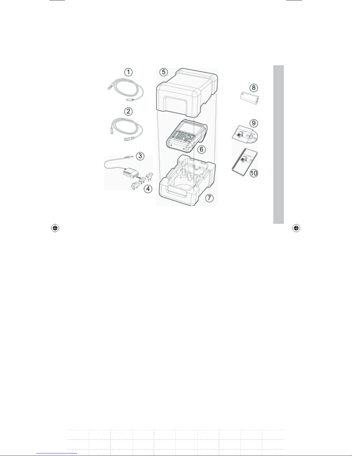
1 USB cable
2 LAN cable
3 Power supply
4 AC supply plug (country-specifi c)
5 Upper shell
6 R&S FSH
7 Lower shell
8 Lithium ion battery
9 CD-ROM
29
10 Quick Start manual
E-02
Page 32
30
2.2.2 Setting up the Instrument
The Handheld Spectrum Analyzer R&S FSH
has been designed for operation in labs as well
as for on site use for service and maintenance
applications.
For any application, the R&S FSH can be set up to
optimize ease of operation and the viewing angle
of the display.
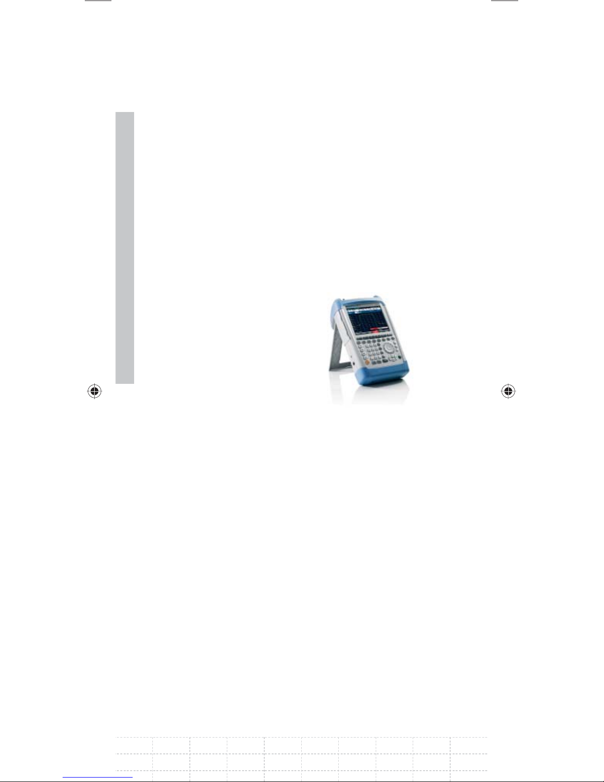
When used as a desktop
instrument, the R&S FSH can
either be laid fl at or it can be
propped up using the fold-out
support at the back.
The R&S FSH can be laid fl at
for operation from above.
Because the grip is slightly raised at the back, the
R&S FSH is tilted forward to give the optimum
viewing angle for the display.
For use as a desktop, fold out the support at the
rear so that the instrument can easily be operated
from the front and the display can be read easily
(see fi gure above).
For on-site installation and service measurements,
it is best to hold the instrument with both hands.
All the controls are easy to reach (e.g. with your
thumbs). Use of the R&S HA-Z222 carrying bag is
recommended in order to leave both hands free for
work on the device under test.
PD 1309.6269.62-02
Page 33
The carrying handle at the top of the R&S FSH can
also be used to hang it from cabinet doors, for
example. The shape of the grip ensures that the
instrument does not fall off.
2.2.3 Switching on the Spectrum
Analyzer
The rechargeable lithium ion battery included
in the delivery must be inserted into the battery
compartment before the R&S FSH is switched on.
The battery compartment is situated at the lower
right corner of the instrument.
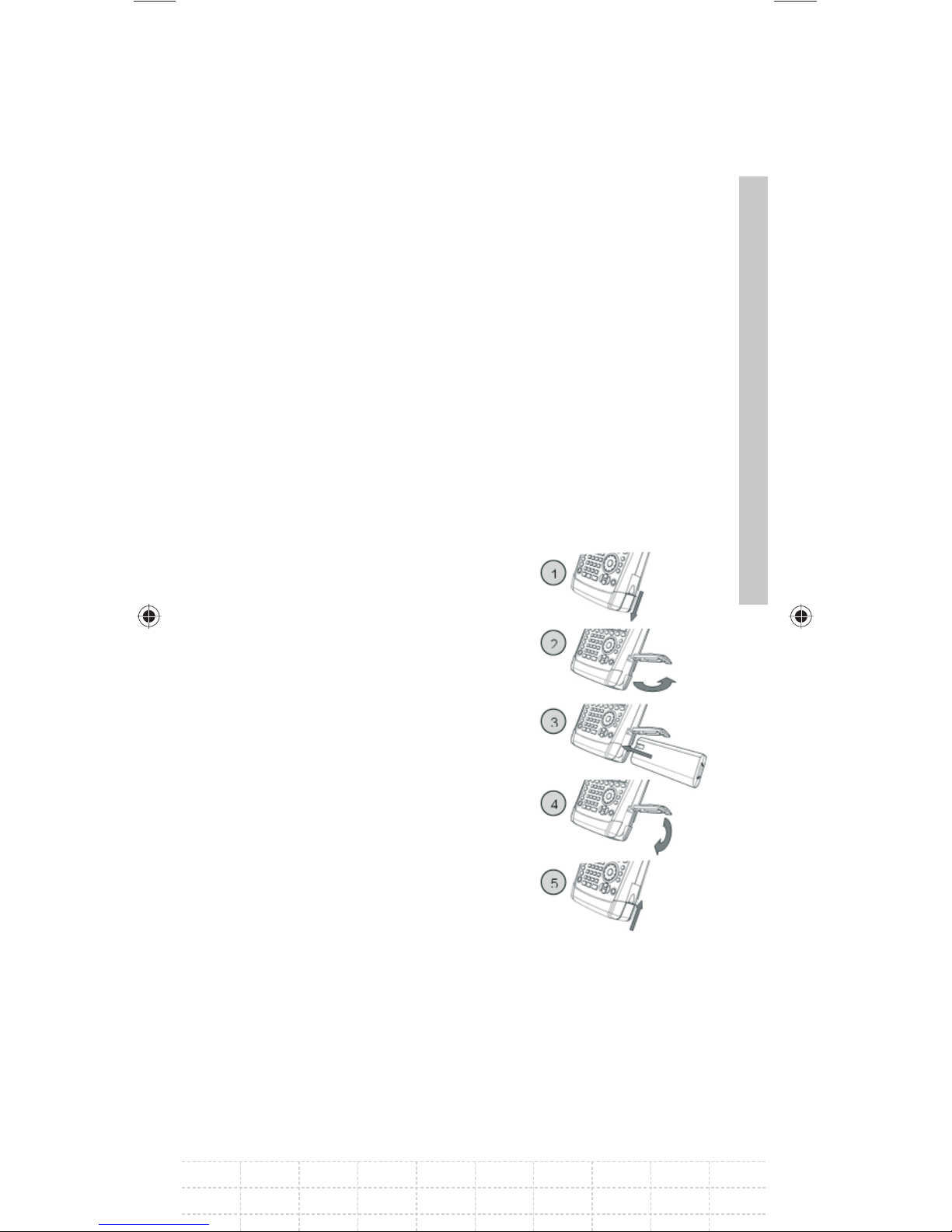
To open the battery
compartment, push the cover
downward by pressing a
fi nger against the recessed
grip (1). Then open the cover
upwards (2) and put the
rechargeable battery into the
R&S FSH as far as it will go
with the beveled side facing
upward and the grip on the
right side (3). To close the
31
cover, fold it downward (4)
and push it upward until it
clicks fully into place (5).
The R&S FSH can be operated with the AC
power supply included in the delivery or with the
replaceable battery. The lithium ion battery which
is supplied has a capacity of approximately 4 Ah
and permits up to three hours’ operation when
fully charged. The R&S FSH battery may not be
E-02
Page 34
32
fully charged when it is dispatched. For battery
operation it must therefore fi rst be charged. The
charging time when the instrument is switched
off is approximately 2.5 hours. If the instrument
is switched on, the charging time is extended by
approximately one hour to 3.5 hours. An R&S
HA-Z203 external charger is available to charge
an additional replacement battery. Another battery
(R&S FSH-Z206) with a capacity of approximately
6 Ah and an operating time of approximately 4.5
hours is additionally available as an accessory.
For use with the supplied power supply
R&S HA-Z201 the power adapter jack plug should
be pushed into the POWER ADAPTER socket on the
left side of the instrument. Then connect the power
supply unit to an AC outlet. The voltage range of the
power supply unit is 100 V to 240 V AC.
Risk of damage to the instrument
Only use the supplied power supply •
R&S HA-Z201.
AC supply voltage must be compatible to the •
voltage specifi ed on the power supply unit.
Attach the appropriate adapter to the power •
supply.
During operation in the fi eld, the battery can
be charged with the R&S HA-Z202 car adapter
plugged into the cigarette lighter socket.
PD 1309.6269.62-02
Page 35
Turn off the R&S FSH while driving or while the
engine is on.
Operation of the R&S FSH via the cigarette lighter
socket while driving or while the engine is on is
prohibited.
To switch on the R&S FSH, press the yellow button
at the bottom left of the front panel.
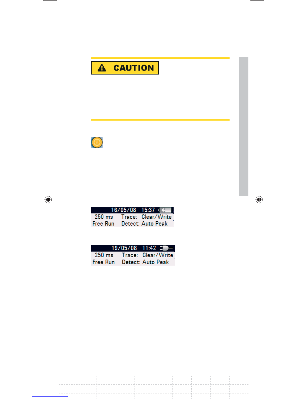
The R&S FSH displays an arrow within the battery
charge status indicator at the top right of the
display to show that it is connected to the mains
and is charging. If the battery is fully charged, a
plug icon is displayed instead of the battery icon.
33
Battery is chargingFig.:
R&S FSH is being powered by the AC supply and Fig.:
the battery is fully charged
When the R&S FSH is switched on, it recalls the
settings that it was using when it was last switched
off.
E-02
Page 36
34
If the internal battery is completely fl at,
the R&S FSH cannot be switched on even
though it is connected to the AC supply
via the power supply unit. In this case,
the internal battery must be charged for
a while with the instrument switched off.
Only then can the instrument be switched
on.
2.2.4 Charging the Battery
The R&S FSH is fi tted with a replaceable lithium
ion battery. The operating time depends on the
battery’s charge status, the ambient temperature
and the operating mode. The operating times for
a fully charged battery at room temperature in the
operating mode SPECTRUM is shown in the table
below:
Battery type: R&S HA-Z204 (supplied)
Operating time: approx. 3 h
Battery type: R&S HA-Z206 (available as an
accessory)
Operating time: approx. 4.5 h
The R&S FSH battery is not fully charged
at time of delivery. Therefore it must be
charged after delivery.
When stored over an extended period, selfdischarging reduces the battery charge. The battery
should therefore be charged before use if it is
going to be the sole power source for a long period
of operation.
PD 1309.6269.62-02
Page 37
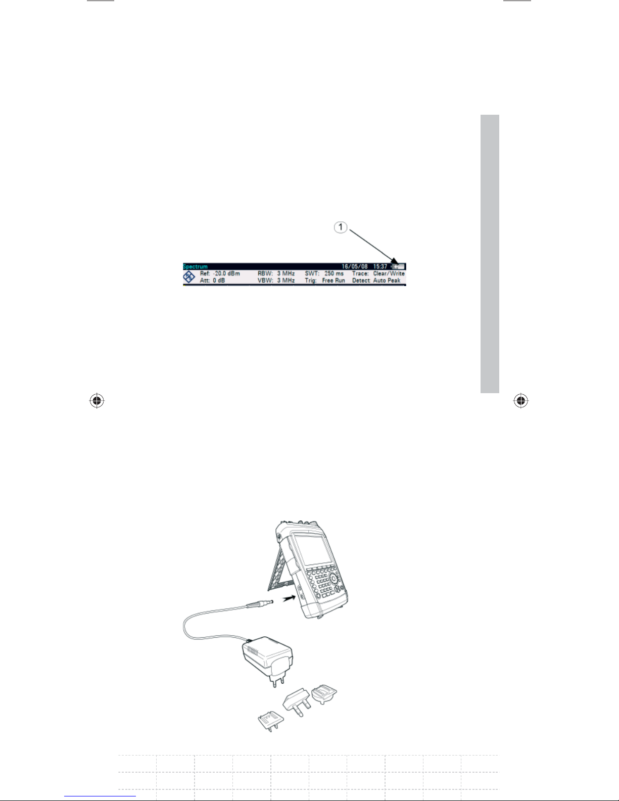
The battery’s charge status is shown at the top
right of the screen (see fi gure below). If the battery
is fully charged, the battery icon is fi lled white.
As the battery discharges, the white coloring
disappears in four steps until just the battery
outline indicates that the battery is fl at.
Battery charge state (1)Fig.:
Using the supplied power supply unit or the car
adapter
The battery is charged via the included power
supply unit or the R&S HA-Z202 car adapter (order
number 1309.6117.00) which is connected to the
35
jack on the right-hand side of the carrying handle.
If required, equip the power supply unit with the
country-specifi c plug. Remove the plug from the
power supply unit toward the front and fi rmly
connect the appropriate plug to the power supply
unit.
E-02
Page 38

For rapid charging, be sure to switch off the
R&S FSH during charging. If the R&S FSH is
switched on, the charging current is reduced by
the power drain of the instrument. Battery charging
therefore takes longer.
The charging times are shown below:
36
Battery type: R&S HA-Z204 (supplied)
Charging time (R&S FSH switched off):
approx. 2.5 h
Charging time (R&S FSH switched on):
approx. 3.5 h
Battery type: R&S HA-Z206 (available as an
accessory)
Charging time (R&S FSH switched off):
approx. 3.5 h
Charging time (R&S FSH switched on):
approx. 4.5 h
To lengthen the operating time with one battery
charge, the R&S FSH has an automatic cut-off
circuit for the display background lighting after
a selectable time (0 to 99 minutes) after the last
input. The cut-off is deactivated in the default
setting.
PD 1309.6269.62-02
Page 39
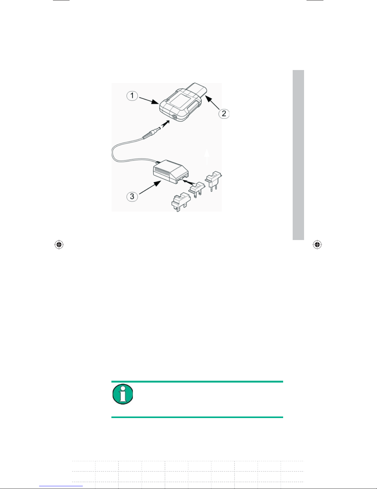
Using the R&S HA-Z203 battery charger
1 External charger R&S HA-Z203
2 Lithium ion battery R&S HA-Z204 or HA-Z206
3 Power supply unit R&S HA-Z201 or
37
R&S HA-Z202 car adapter
For external charging, the lithium ion battery is
plugged into the R&S HA-Z203 external charger
(available as an accessory: order number
1309.6123.00) and supplied with current via the AC
power supply. The charging process is indicated by
the orange LED (CHARGE) on the charger. As soon
as the battery is fully charged, this LED goes off
and the green LED labeled READY begins to light
up. The auto power down mode is deactivated in
the default setting.
The R&S HA-Z203 external charger can
also be powered by the R&S HA-Z202 car
adapter.
E-02
Page 40
38
2.2.5 Spectrum Analyzer Connectors
The R&S FSH has the following connections on the
upper side:
RF input
Connect the RF input via a cable with an
N connector to the DUT. Make sure that it is not
overloaded.
The maximum permissible continuous power
at the RF input is 20 dBm (100 mW). It can be
loaded with up to 30 dBm (1 W) for a maximum
of three minutes. If the instrument is loaded with
1 W for longer, it may be destroyed. The RF input
is protected from static discharges and voltage
pulses by a limiting circuit.
Risk of electrical shock
In order to avoid electrical shock the DC input
voltage must never exceed the value specifi ed on
the housing.
Risk of damage to the coupling capacitor, the
input attenuator and the mixer
The DC input voltage must never exceed the value
specifi ed in the data sheet.
PD 1309.6269.62-02
Page 41

Tracking generator output
(general output, models 1309.6000.14, 1309.6000.18,
1309.6000.24 and 1309.6000.28 only)
The tracking generator output power for the
different R&S FSH models is as follows:
Model: R&S FSH4 (1309.6000.14, 1309.6000.18)
Frequency: 100 kHz to 3.6 GHz
Tracking generator output power: 0 dBm nominal
Model: R&S FSH8 (1309.6000.24, 1309.6000.28)
Frequency: 300 kHz to 3.6 GHz
Tracking generator output power: 0 dBm nominal
Model: R&S FSH8 (1309.6000.24, 1309.6000.28)
Frequency: 3.6 GHz to 8 GHz
39
Tracking generator output power: -5 dBm nominal
The tracking generator output power can be
reduced with an integrated step attenuator by a
maximum of 40 dB in 1 dB steps in all R&S FSH
models.
Risk of damage to the tracking generator output
The reverse voltage up to the voltage stated on the
R&S FSH housing must not be exceeded.
E-02
Page 42
Connection for the power sensor
The connection is especially confi gured for power
sensors. It is used for both the power supply and
data transfer via the power sensor interface. The
R&S TS-EMF isotropic antenna (order number
1158.9295.13) can additionally be controlled via this
connection.
40
Headphone connection
A 3.5 mm jack is provided for headphones. The
internal impedance of the connector is approx.
10 ohm.
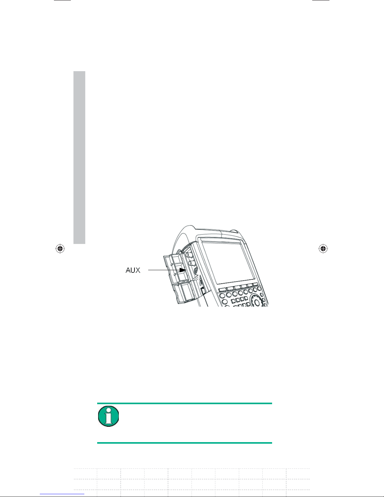
Connection for additional accessories ( AUX)
Further accessories like the GPS receiver (HA-Z240,
order no. 1309.6700.02) can be connected to the
AUX connection on the left side of the instrument.
On the left of the R&S FSH, underneath protective
caps, there are two connections which are
described in more detail below:
Both BNC sockets can be confi gured for
various applications. The names of the
individual connections are embossed on
the insides of the protective covers.
PD 1309.6269.62-02
Page 43
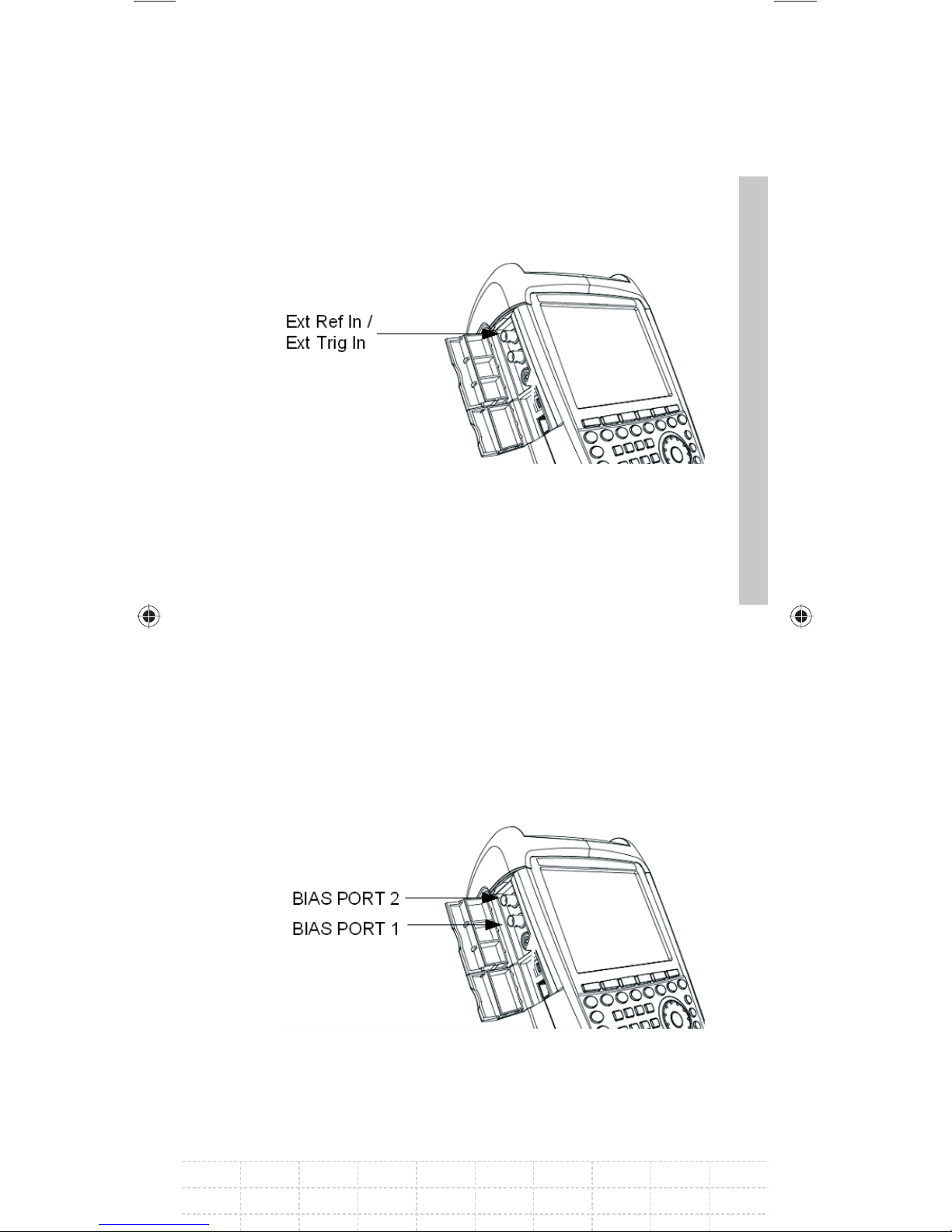
Input for external trigger or external reference
(EXT TRIG/EXT REF)
Either an external trigger signal to start a
measurement or a 10 MHz reference signal
for frequency synchronization is fed in via the
EXT TRIG/EXT REF BNC socket. The trigger
threshold is similar to that of TTL signals. The level
for the reference signal must be larger than 0 dBm.
41
The necessary settings can be entered in the
SETUP menu (SETUP key, INSTRUMENT SETUP
softkey).
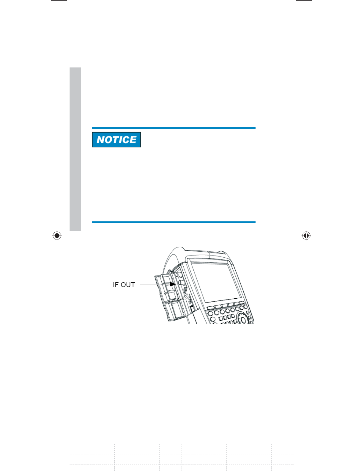
BIAS Port 1/BIAS Port 2 direct current inputs
(for models 1309.6000.24 and 1309.6000.28 only)
E-02
Page 44
42
Active equipment under test can be supplied with
power via the BIAS Port 1 and BIAS Port 2 direct
current inputs. Direct current is supplied with the
assistance of a suitable power adapter (600 mA
max. / 50 V max.).
Risk of damage to the instrument
Never apply currents above> 600 mA or voltages
above 20 V to the BNC sockets if the BNC
connectors are not confi gured as BIAS input ports.
If the BNC connectors are confi gured as BIAS
input ports never apply currents above> 600 mA or
voltages above 50 V.
IF output (IF-Out)/Video Out
The BNC socket shown in the diagram above can
be used as an intermediate frequency output
(21.4 MHz) or a video output.
PD 1309.6269.62-02
Page 45
Risk of damage to the instrument
Never apply currents above> 600 mA or voltages
above 20 V to the BNC sockets if the BNC
connectors are not confi gured as BIAS input ports.
If the BNC connectors are confi gured as BIAS
input ports never apply currents above> 600 mA or
voltages above 50 V.
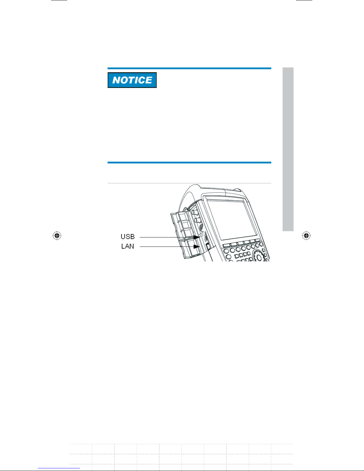
USB and LAN interface
The R&S FSH can be connected to a computer
via either a USB or a LAN interface for data
transfer. The interfaces are on the left side below
a protective cover (see fi gure above). A USB cable
and a LAN connection cable for direct connection
43
to the computer are supplied. The LAN interface is
confi gured via the SETUP key.
E-02
Page 46
44
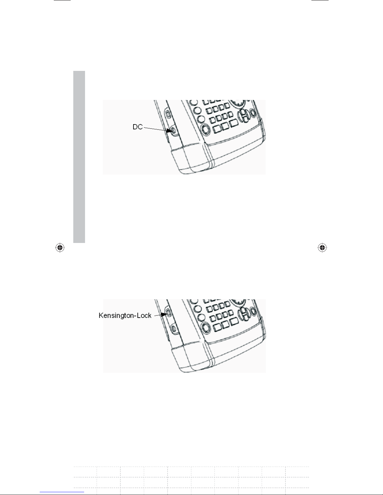
DC connection for supply from the external AC
power supply
The R&S FSH is supplied with current by the AC/DC
transformer power supply via the DC connection,
and the R&S FSH battery is charged.
The internal battery can also be charged from
a vehicle’s cigarette lighter socket. The adapter
required is available as an accessory for the R&S
FSH (R&S HA-Z202, order no. 1309.6117.00).
Mechanical locking device
A Kensington Lock can be anchored in the R&S
FSH housing to mechanically secure the R&S FSH
to a workstation.
PD 1309.6269.62-02
Page 47
2.2.6 Hardware Settings
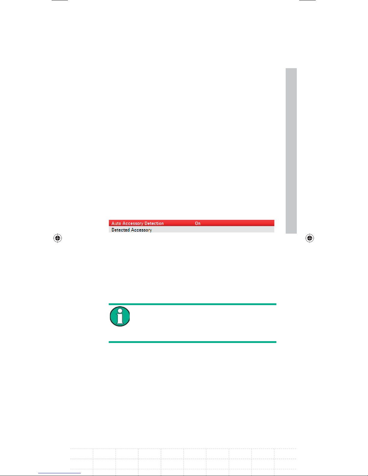
Set the R&S FSH to detect connected accessory
automatically.
Setting the auto accessory detection
Press the SETUP key.
Press the INSTRUMENT SETUP softkey.
The R&S FSH opens a list of general settings.
Select AUTO ACCESSORY DETECTION below the
heading HARDWARE with the rotary knob or the
cursor keys (∧ or ∨).
Confi rm with ENTER.
A submenu opens in which the automatic
detection of accessories is set ON or OFF.
Confi rm with ENTER.
If the connected accessory is detected the
item is displayed in the fi eld DETECTED
ACCESSORY below the heading
HARDWARE.
45
E-02
Page 48
46
2.2.7 Screen Settings
The R&S FSH’s screen is a TFT color LCD. Indoors,
its brightness depends on the intensity of the
backlighting. The viewing angle can be optimized
by adjusting the color setting. To achieve maximum
contrast, the screen can be switched from color
display to black-and-white display. Under extreme
light conditions, it can be advantageous to select
the high-contrast monochrome display.
To strike a balance between battery operating time
and screen display quality, set backlighting to the
minimum brightness needed.
Setting display backlight
Press the SETUP key.
Press the INSTRUMENT SETUP softkey.
The R&S FSH opens a list of general settings.
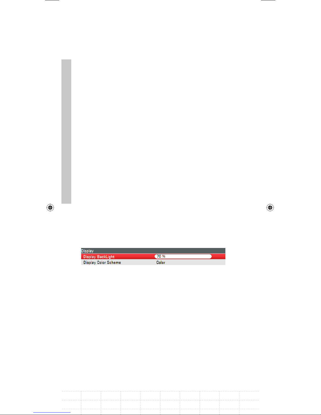
Select DISPLAY BACKLIGHT below the heading
DISPLAY with the rotary knob or the cursor keys
(∧ or ∨).
Confi rm with ENTER.
An input fi eld opens in which the current
background lighting ratio is displayed in percent.
100 % is the maximum brightness.
PD 1309.6269.62-02
Page 49
Enter the desired brightness value with the
rotary knob or the cursor keys in 10 % steps or
enter the value directly via the numeric keys.
Confi rm with ENTER.
The input range lies between 0 % and 100 %.
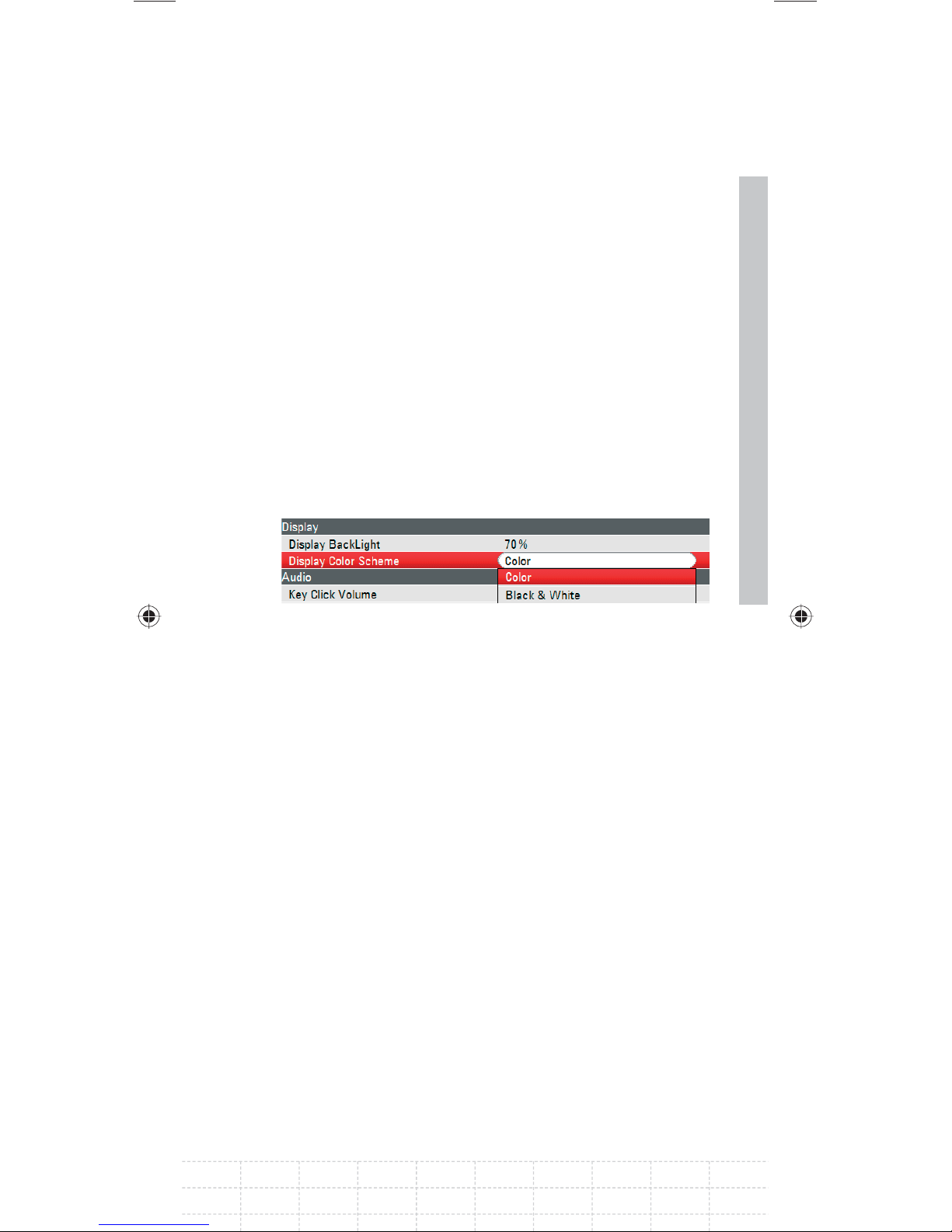
Setting the display color scheme
Press the SETUP key.
Press the INSTRUMENT SETUP softkey.
The R&S FSH opens a list of general settings.
47
Select the DISPLAY COLOR SCHEME menu item
below the heading DISPLAY with the rotary
knob or the cursor keys (∧ or ∨).
Confi rm with ENTER.
A submenu opens.
Select COLOR (color screen display) with
the rotary knob or the cursor keys (∧ or ∨) or
BLACK & WHITE (monochrome display).
Confi rm with ENTER.
E-02
Page 50
2.2.8 Audio Settings
Set the key click volume and the system beeper
volume in the INSTRUMENT SETUP settings.
Setting the key click volume
Press the SETUP key.
48
Press the INSTRUMENT SETUP softkey.
The R&S FSH opens a list of general settings.
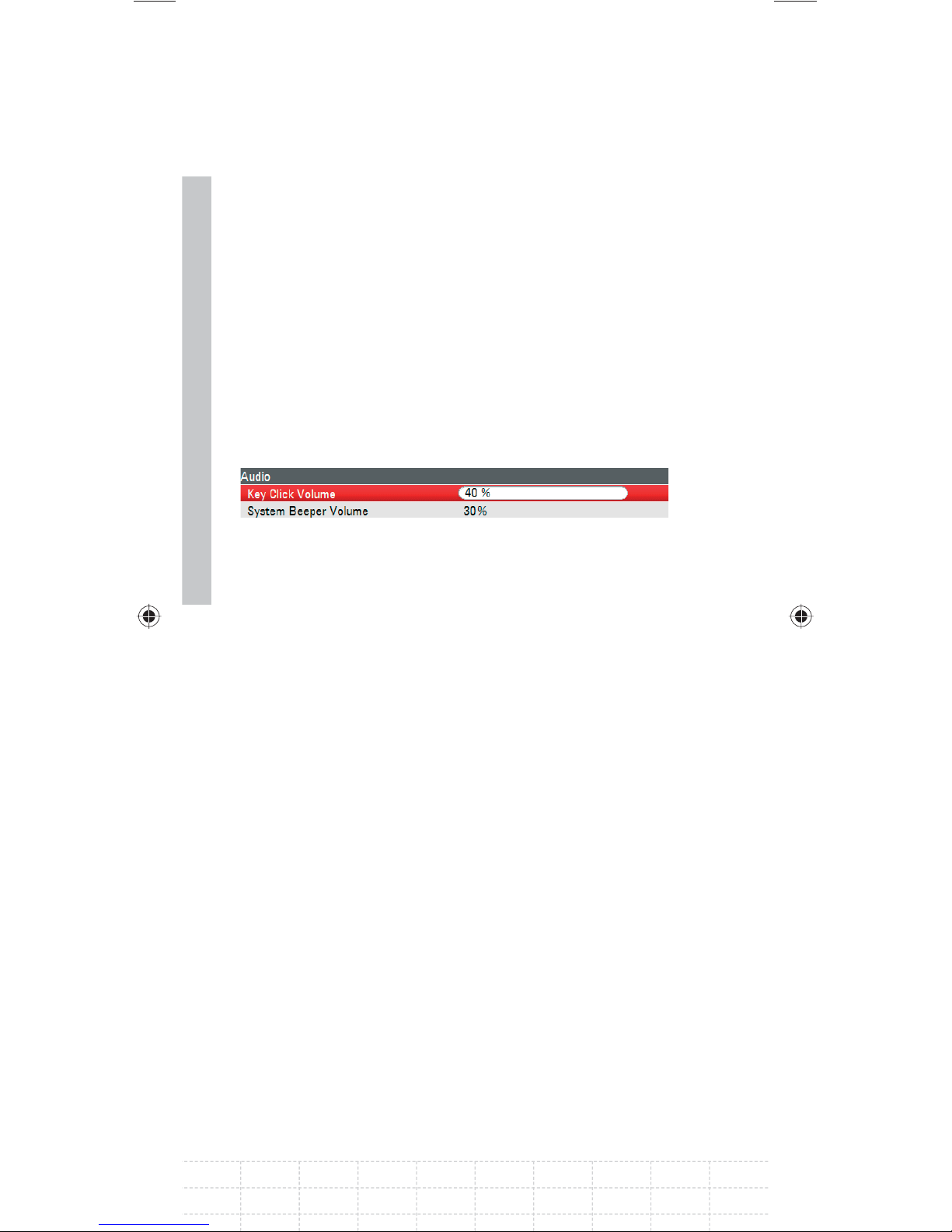
Select KEY CLICK VOLUME below the heading
AUDIO with the rotary knob or the cursor keys
(∧ or ∨).
Confi rm with ENTER.
An input fi eld opens in which the current key click
volume is displayed in percent.
Enter the desired volume value with the rotary
knob or the cursor keys in 10 % steps or enter
the value directly via the numeric keys.
Confi rm with ENTER.
The input range lies between 0 % and 100 %.
PD 1309.6269.62-02
Page 51
Setting the system beeper volume
Press the SETUP key.
Press the INSTRUMENT SETUP softkey.
The R&S FSH opens a list of general settings.
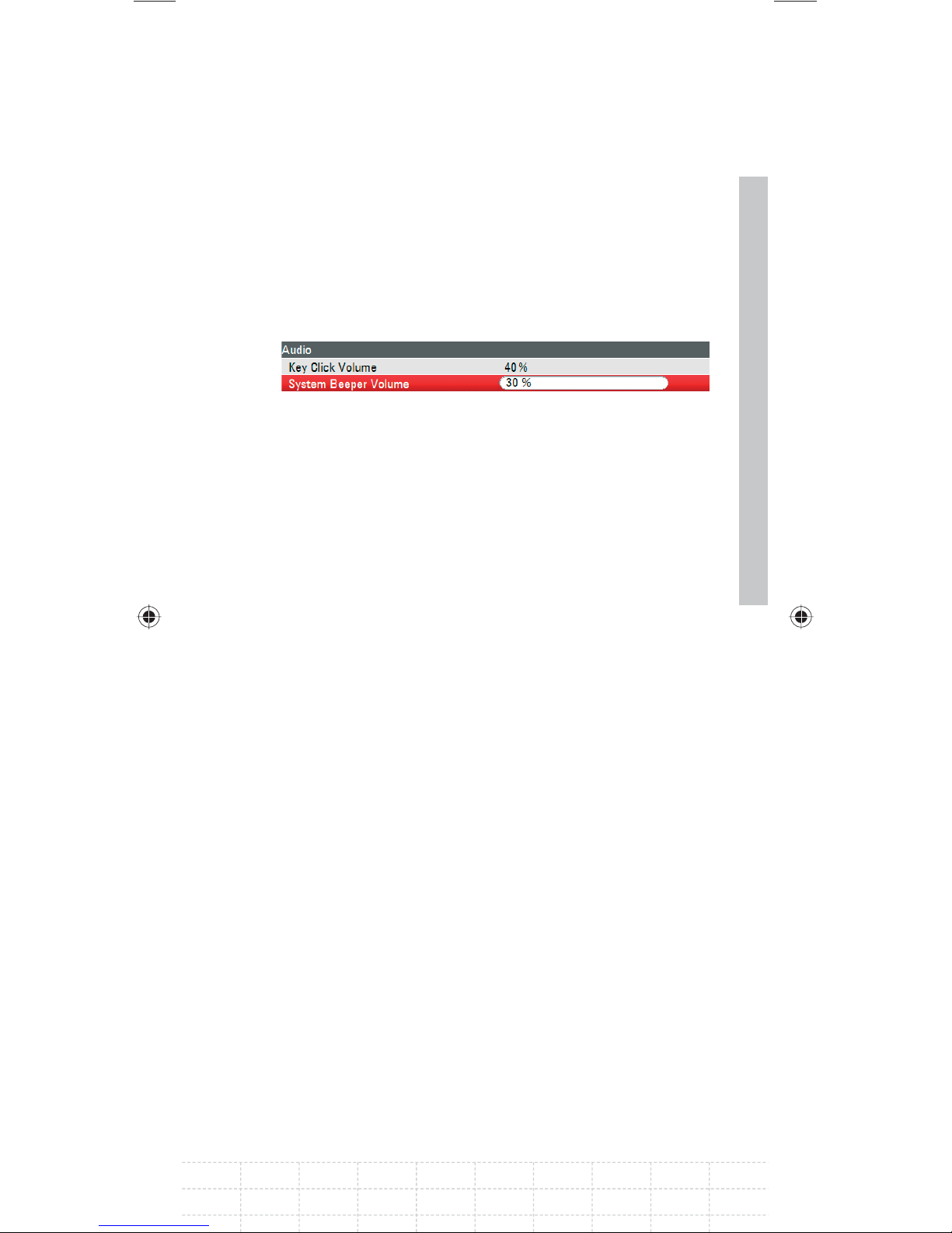
Select SYSTEM BEEPER VOLUME below the
heading AUDIO with the rotary knob or the
cursor keys (∧ or ∨).
Confi rm with ENTER.
An input fi eld opens in which the current system
beeper volume is displayed in percent.
Enter the desired volume value with the rotary
49
knob or the cursor keys in 10 % steps or enter
the value directly via the numeric keys.
Confi rm with ENTER.
The input range lies between 0 % and 100 %.
E-02
Page 52
50
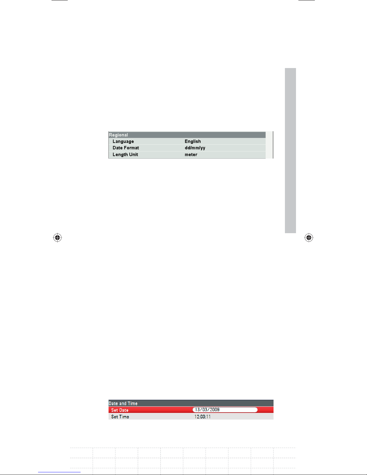
2.2.9 Regional Settings
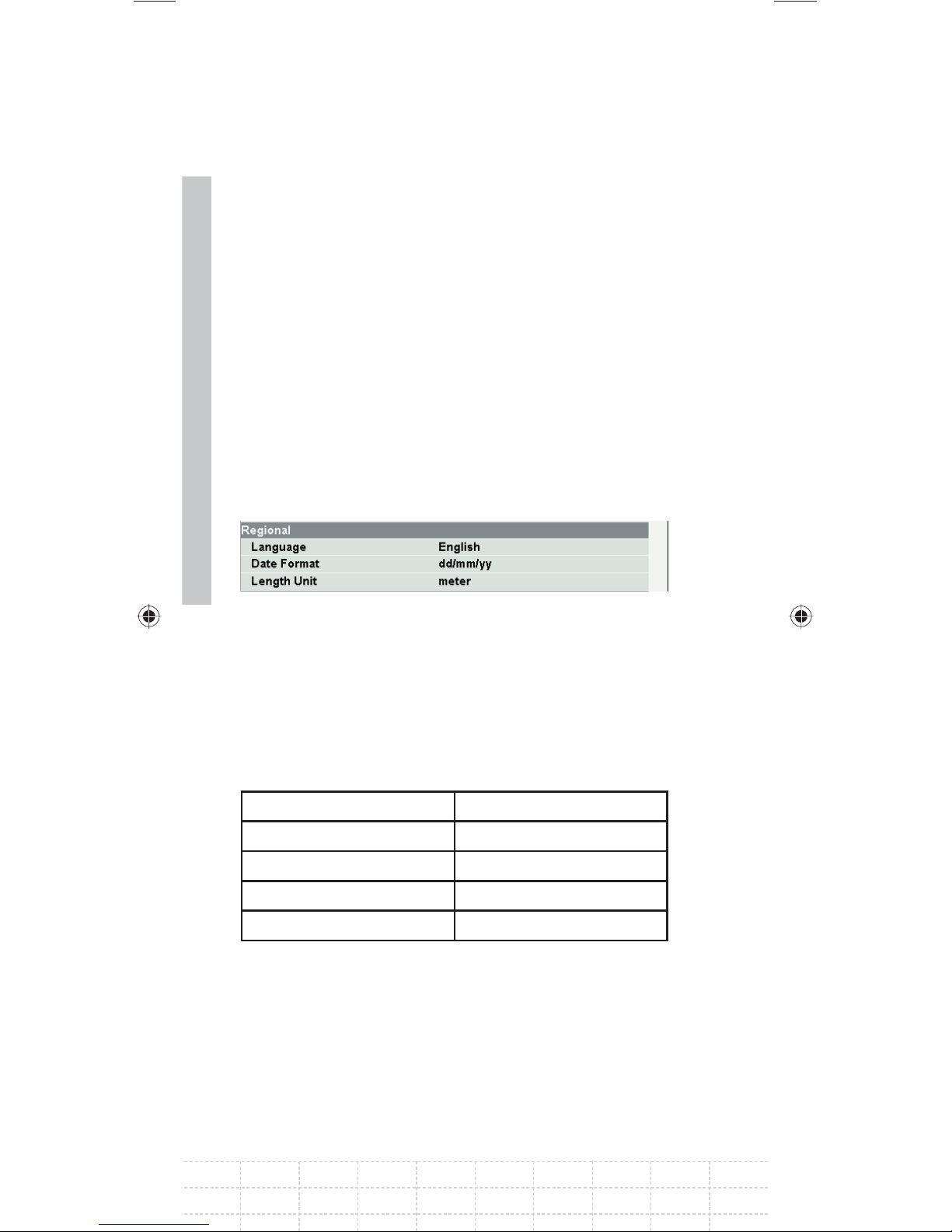
The regional settings allow to select a different
language, date format and length unit. Set the
desired regional settings in the INSTRUMENT
SETUP settings.
Setting the language
Press the SETUP key.
Press the INSTRUMENT SETUP softkey.
The R&S FSH opens a list of general settings.
Select LANGUAGE below the heading
REGIONAL with the rotary knob or the cursor
keys (∧ or ∨).
Confi rm with ENTER.
A list opens in which the supported languages are
itemized:
Chinese Korean
French Portuguese
German Russian
Italian Spanish
Japanese
Select the desired language with the rotary
knob or the curser keys.
Confi rm with ENTER.
PD 1309.6269.62-02
Page 53
Setting the date format
Press the SETUP key.
Press the INSTRUMENT SETUP softkey.
The R&S FSH opens a list of general settings.
Select DATE FORMAT below the heading
REGIONAL with the rotary knob or the cursor
keys (∧ or ∨).
Confi rm with ENTER.
A submenu appears.
Select DD/MM/YY or MM/DD/YY with the rotary
51
knob or the cursor keys (∧ or ∨).
Confi rm with ENTER.
2.2.10 Setting the Date and Time
The R&S FSH has an internal clock that can apply
a date and time stamp. The user can reset the date
and time.
Setting the date
Press the SETUP key.
Press the INSTRUMENT SETUP softkey.
The R&S FSH opens a list of general settings.
E-02
Page 54
52
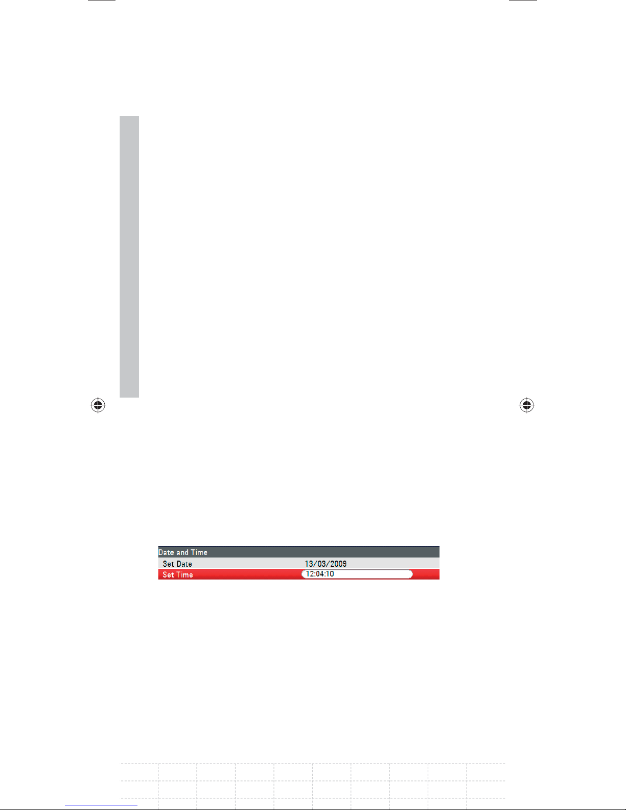
Select the SET DATE menu item below the
heading DATE AND TIME with the rotary knob
or the cursor keys (∧ or ∨).
Confi rm with ENTER.
An input fi eld opens. In the input fi eld, the date is
shown in the currently selected format:
dd/mm/yyyy or mm/dd/yyyy.
Depending on the date format, change the day
(dd) or month (mm) with the rotary knob, cursor
keys or a numerical entry.
Confi rm with ENTER.
The cursor then automatically moves to the second
fi eld in the date (day or month, depending on the
date format). Proceed with the next two fi elds as
with the fi rst.
Setting the time
Press the SETUP key.
Press the INSTRUMENT SETUP softkey.
The R&S FSH opens a list of general settings.
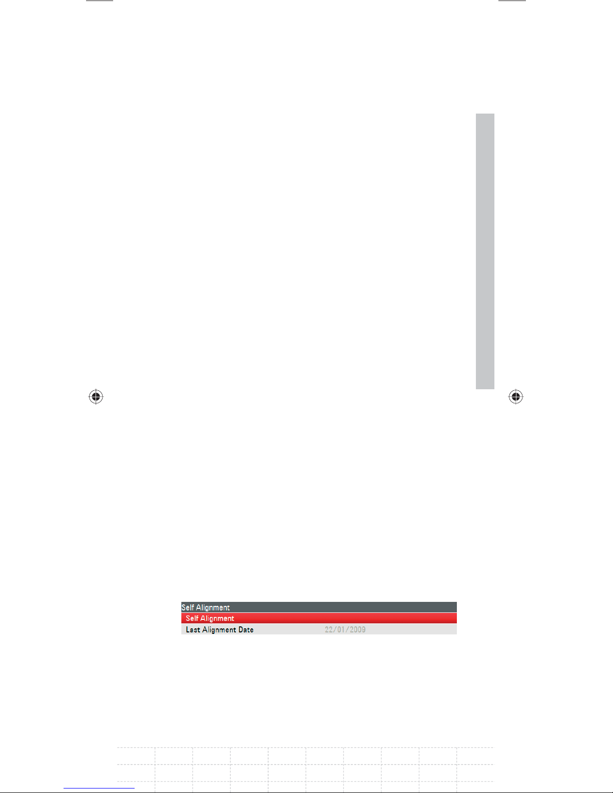
Press the SETUP key. Select the SET TIME
menu item below the heading DATE AND TIME
with the rotary knob or the cursor keys (∧ or ∨).
Confi rm with ENTER.
The currently set time appears in “hours:minutes”
format in the input fi eld.
PD 1309.6269.62-02
Page 55
Change the hours with the rotary knob, the
cursor keys or by numeric input.
Confi rm with ENTER.
After input, the cursor automatically moves to the
minutes display. Input is identical to the procedure
for setting the hour display.
After the minutes have been entered, the R&S FSH
verifi es the validity of the entered time. If the time
is not valid, the R&S FSH sets the next valid time.
2.3 Self Alignment
The self alignment calibrates the instrument
settings for vector network analyzer and overrides
the manufacturer’s calibration stored in the
instrument.
For the self alignment a short circuit (Short), an
open circuit (Open) and 50 ohm match (Load) is
required. In addition, a through connection must
be established with an appropriate cable.
Press the SETUP key.
53
Press the INSTRUMENT SETUP softkey.
The R&S FSH opens a list of general settings.
Select the SELF ALIGNMENT menu item below
the heading SELF ALIGNMENT with the rotary
knob or the cursor keys (∧ or ∨).
Confi rm with ENTER.
E-02
Page 56
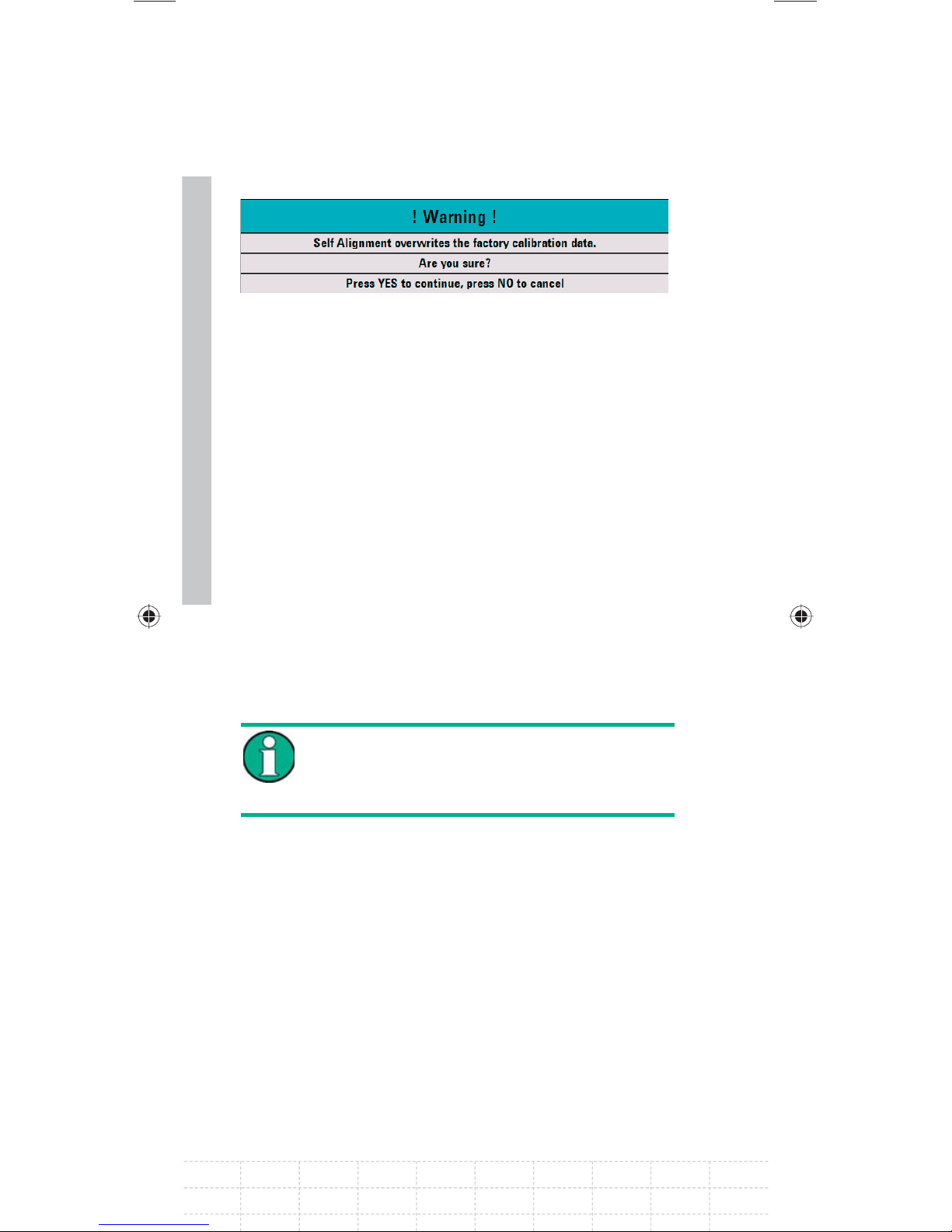
A warning is shown:
Pressing YES will perform the self alignment.
Pressing NO discards this action. Follow the
54
instructions displayed on the screen.
2.4 Setting the Instrument Default
Setup
2.4.1 Setting Preset
The PRESET key sets the R&S FSH to the default
setup. This allows a new confi guration based on
defi ned measurement parameters to be entered,
without parameters from a previous setting
unintentionally still being active.
Setting the instrument to default setup
only affects the present mode you are
working with.
Press the PRESET key.
The R&S FSH is set to the default setup. The span
depends on the model. With the R&S FSH4, it is 3.6
GHz; with the R&S FSH8 it is 8 GHz.
PD 1309.6269.62-02
Page 57
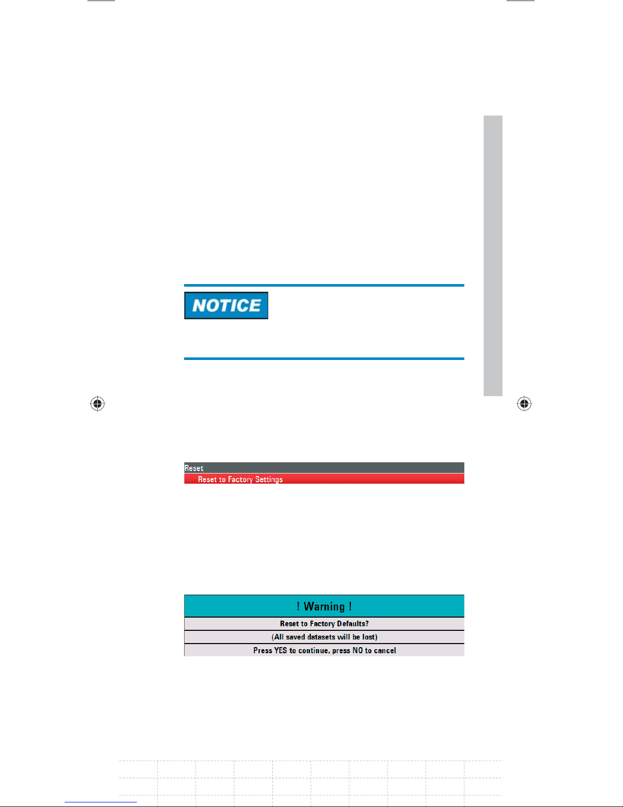
2.4.2 Reset to Factory Settings
RESET TO FACTORY SETTINGS set the R&S FSH to
factory defaults. All settings in the different menus
are set to the original factory settings and all saved
datasets, user defi ned transducer factors, limit
lines, standards, channel tables and cable models
will be deleted. Only the factory default fi les will be
re-installed.
Risk of data loss
All saved datasets will be lost.
Press the SETUP key.
Press the INSTRUMENT SETUP softkey.
55
The R&S FSH opens a list of general settings.
Select RESET TO FACTORY SETTINGS with the
rotary knob or the cursor keys (∧ or ∨).
Confi rm with ENTER.
A warning is shown.
Pressing YES will perform the reset. Pressing
NO discards this action. If YES is pressed, an
information window is shown during the device
rebooting.
E-02
Page 58
56
2.5 Selecting External Reference /
External Trigger / Direct Current
Input (BIAS Port 2)
The Ext Trig / Ext Ref BNC connector on top of
the R&S FSH can be used either as an input for
an external trigger or an external reference. The
BNC socket can additionally be used as a direct
current input for PORT 2 (BIAS PORT 2) (see also
the chapter on spectrum analyzer connections)
Switchover is via the SETUP menu.
Press the SETUP key.
Press the INSTRUMENT SETUP softkey.
The R&S FSH opens a list of general settings.
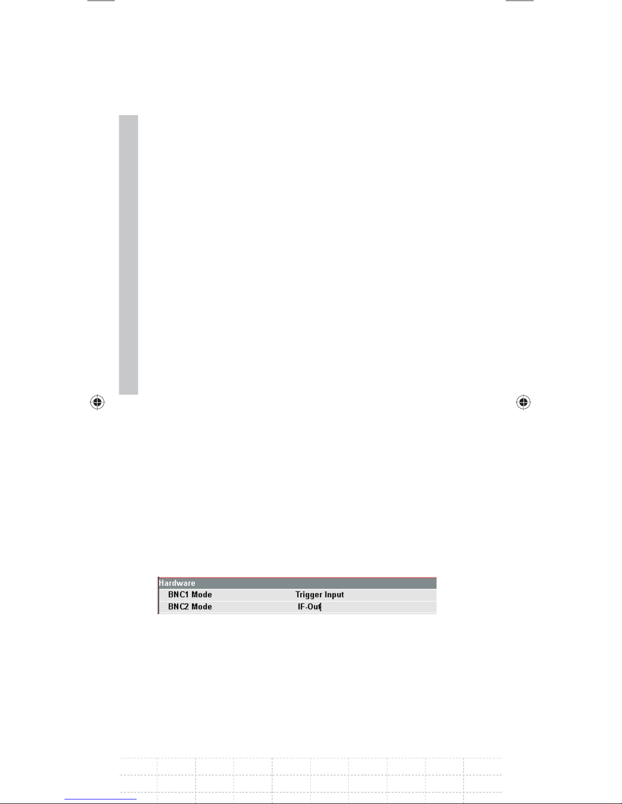
Select menu item BNC1 MODE below the
heading HARDWARE with the rotary knob or
the cursor keys (∧ or ∨).
Confi rm with ENTER.
A selection list opens.
Select the desired function for the BNC socket
with the rotary knob or the cursor keys (∧ or ∨).
Confi rm with ENTER.
PD 1309.6269.62-02
Page 59

Risk of damage to the instrument
Never apply currents above> 600 mA or voltages
above 20 V to the BNC sockets if the BNC
connectors are not confi gured as BIAS input ports.
If the BNC connectors are confi gured as BIAS
input ports never apply currents above> 600 mA or
voltages above 50 V.
The EXT TRIG setting is only for input
confi guration. The use of the external trigger must
be set in the SWEEP menu (SWEEP key, TRIGGER
softkey).
If the input is confi gured for the external reference
and if no reference signal is present at the input,
a warning will appear on the screen. This is meant
to prevent users from carrying out a measurement
57
without a valid reference.
2.6 Selecting the Intermediate
Frequency Output ( IF Out) / Direct
Current Input (BIAS Port 1)
The IF-Out / BIAS Port 1 BNC socket on the left
side of the R&S FSH can be used either as an
intermediate frequency output / video output or
as a direct current input for PORT 1 (BIAS PORT 1)
(see also the chapter on spectrum analyzer
connections).
The selection is located in the setup menu.
E-02
Page 60
Press the SETUP key.
Press the INSTRUMENT SETUP softkey.
The R&S FSH opens a list of general settings.
58
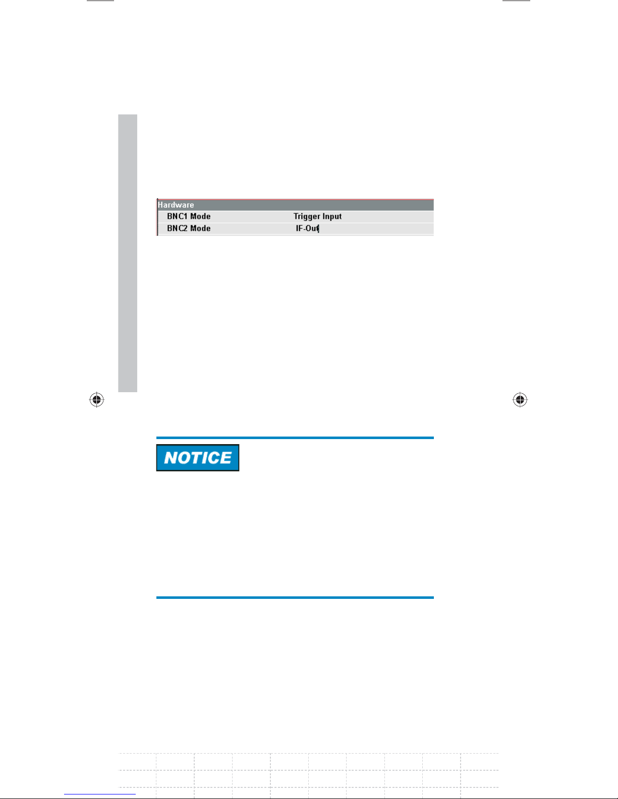
Select the BNC2 MODE menu item below the
heading HARDWARE with the rotary knob or
the cursor keys (∧ or ∨).
Confi rm with ENTER.
A selection list opens.
Select the desired function for the BNC socket
with the rotary knob or the cursor keys (∧ or ∨).
Confi rm with ENTER.
Risk of damage to the instrument
Never apply currents above> 600 mA or voltages
above 20 V to the BNC sockets if the BNC
connectors are not confi gured as BIAS input ports.
If the BNC connectors are confi gured as BIAS
input ports never apply currents above> 600 mA or
voltages above 50 V.
PD 1309.6269.62-02
Page 61
2.7 Enabling Options
The R&S FSH can be fi tted with options (e.g.
distance-to-fault measurements on cables) which
are enabled by entering a key code. The key code
is based on the unique serial number of the
instrument. To add an option, enable it with a key
code.
Operation
Press the SETUP key.
Press the INSTALLED OPTIONS softkey.
Select INSTALL OPTION... under the OPTION
ADMINISTRATION header.
Confi rm with ENTER.
An entry box in the lower right corner of the screen
59
is displayed.
Type in the the appropriate option key.
Confi rm with ENTER.
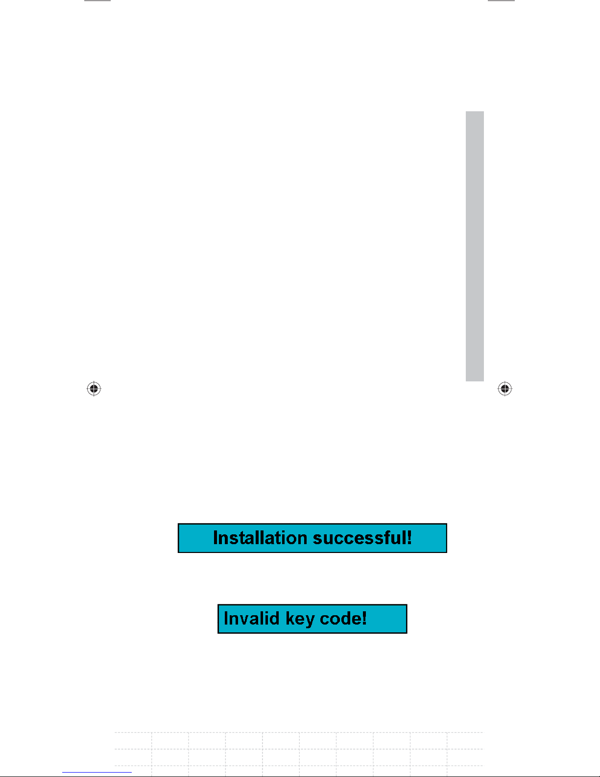
If the key entry was successful, the following
notifi cation is given in the bottom of the screen:
If the key entry failed, the following notifi cation is
given in the bottom of the screen:
The correct key code can then be entered.
E-02
Page 62
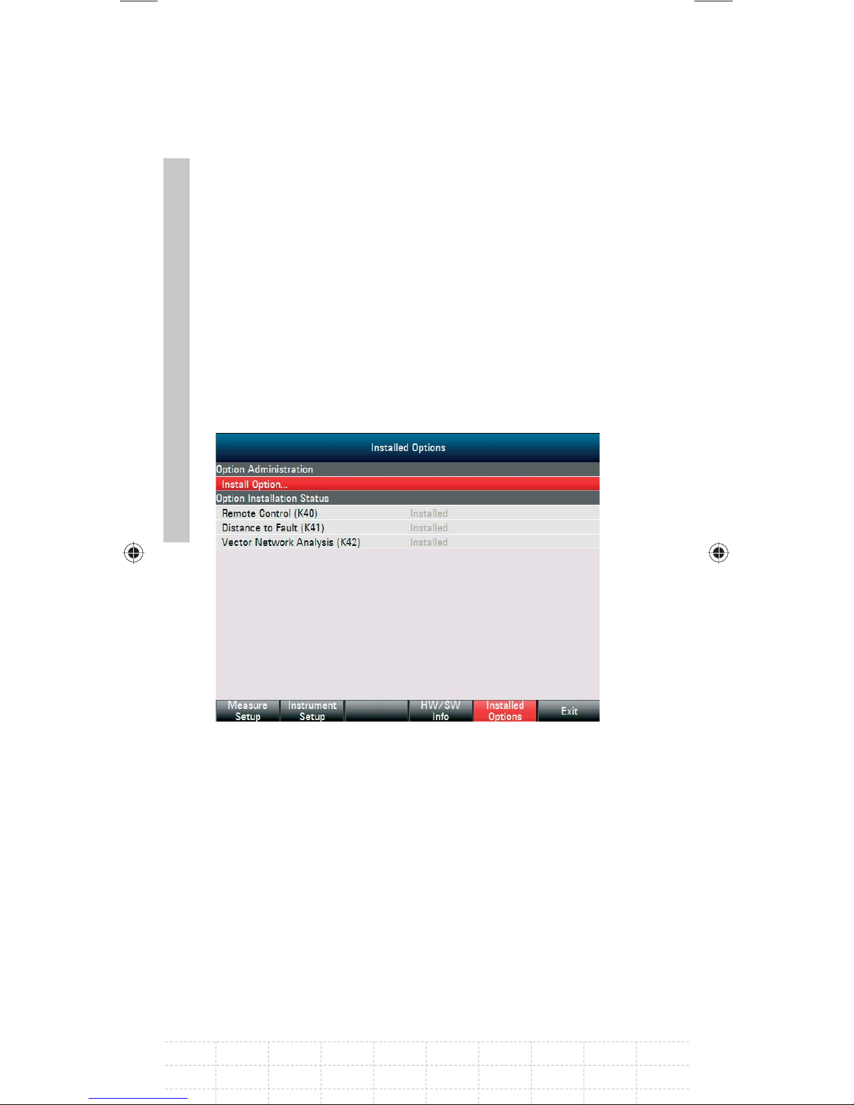
2.8 Checking the Installed Options
The R&S FSH displays the installed options in the
Setup menu so you can check them:
Press the SETUP key.
Press the INSTALLED OPTIONS softkey.
60
The R&S FSH displays all available options with
the appropriate status below the header OPTION
INSTALLATION STATUS.
If an option is installed, the installation status
differs for permanent or temporary installed
options.
PD 1309.6269.62-02
Page 63

2.9 Setting up a LAN or USB
Connection to a PC
The powerful R&S FSH4View software is available
to document measuring results, create limit lines,
channel tables, etc. The software is supplied with
the R&S FSH. Connection to a PC is possible via
either LAN or USB. The following description
covers the main steps for setting up the connection
between the R&S FSH and the R&S FSH4View
software.
The R&S FSH4View software must be installed on
the PC before the connection is made. To do this,
place the CD-ROM supplied in the CD drive. From
the autostart menu select menu item FSH4View to
install the software. Follow the instructions on the
screen.
61
If no connection can be established
between the R&S FSH4View software
and the R&S FSH following successful
confi guration, please check the fi rewall
settings on your PC.
2.9.1 Direct connection via LAN
Connect the R&S FSH directly to the PC with the
LAN cable supplied. The R&S FSH LAN interface is
situated on the left side underneath a protective
cap (see also the chapter on spectrum analyzer
connections).
E-02
Page 64
62
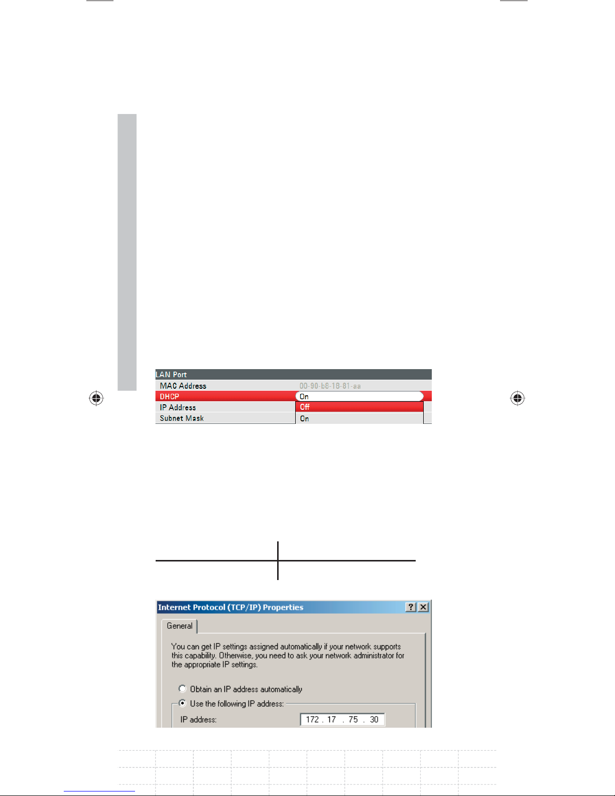
DHCP is switched on by default on the R&S FSH.
DHCP on the R&S FSH must be switched off for a
direct connection.
Press the SETUP key.
Press the INSTRUMENT SETUP softkey.
The R&S FSH opens a list with the general settings.
Select the DHCP MODE menu item below the
heading LAN PORT with the rotary knob or the
cursor keys (∧ or ∨) and confi rm with ENTER.
A list opens. Select OFF with the rotary knob or
the cursor keys (∧ or ∨) and confi rm with the
ENTER key. DHCP is now deactivated.
Setting the IP address
To establish the connection, the IP address of the
PC used and that of the R&S FSH must be identical,
except for the digits following the last dot.
Example:
PC IP address: 172.76.68.30
R&S FSH IP address: 172.76.68.24
IP address set on the PCFig.:
PD 1309.6269.62-02
Page 65
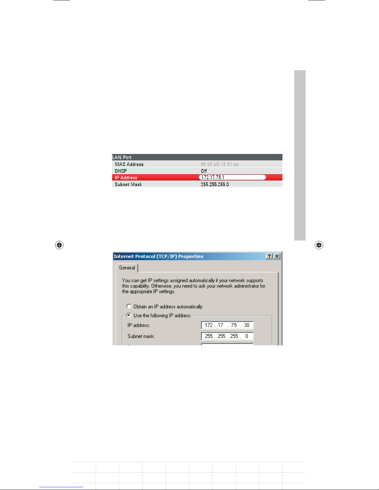
Select the IP ADDRESS menu item from the list
under the heading LAN PORT with the rotary
knob or the cursor keys (∧ or ∨) and confi rm
with ENTER.
An input fi eld opens. Enter the IP address of
the PC (e.g. 172.76.68.24) with the numeric keys
and confi rm with the ENTER key.
Setting the IP address on the R&S FSHFig.:
Setting the subnet mask
The PC’s and the R&S FSH’s subnet mask must
also match in order to make a connection.
63
Select the SUBNET MASK menu item from
the list below the heading LAN PORT with the
rotary knob or the cursor keys (∧ or ∨) and
confi rm with ENTER.
Subnet mask set on the PCFig.:
E-02
Page 66
64
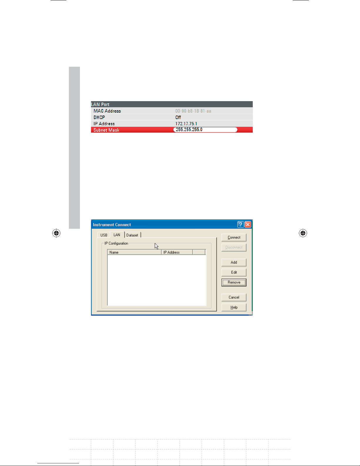
An input fi eld opens. Enter the subnet mask
used on the PC, e.g. 255.255.255. 0 with the
numeric keys and confi rm with the ENTER key.
Setting the subnet mask on the R&S FSHFig.:
R&S FSH4View software confi guration:
Start the R&S FSH4View software on the PC.
Select the LAN tab in the INSTRUMENT
CONNECT dialog window.
Click ADD to create a new network connection.
Enter the name for the new network connection
in the open window, e.g. R&S FSH4.
Enter the IP address set for the R&S FSH in the
IP Address input fi eld, in this case 172.76.68.24,
and confi rm with OK.
PD 1309.6269.62-02
Page 67
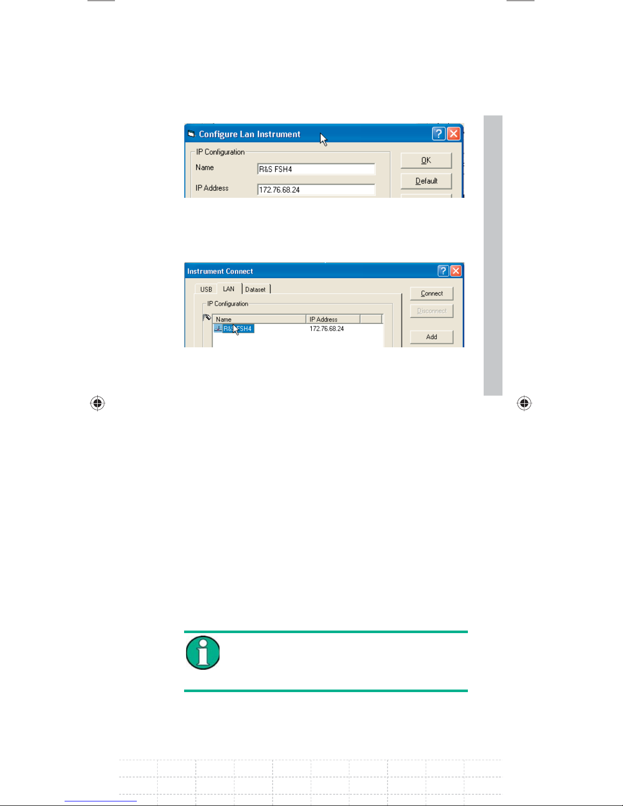
The connection is now confi gured and appears in
the INSTRUMENT CONNECT window.
Select the new connection named “R&S FSH4”
and make the connection to the R&S FSH with
CONNECT.
2.9.2 Connection via an existing LAN
network
The R&S FSH’s IP address can be automatically
drawn from the DHCP server, or a fi xed
65
address can be defi ned manually. With manual
allocation, a fi xed IP address and subnet mask
must be assigned to the R&S FSH as described
in the chapter on direct LAN connection. The
R&S FSH4View software must then be confi gured
as described with the assigned IP address.
Contact your IT system manager to obtain
a free IP address.
E-02
Page 68
66
In networks with a DHCP server, the Dynamic
Host Confi guration Protocol (DHCP) permits
automatic allocation of the network confi guration
to the R&S FSH connected via LAN cable. For this
purpose, DHCP must be active on the R&S FSH.
DHCP is switched on by default on the R&S FSH. If
the setting has been altered, proceed as follows:
Press the SETUP key.
Press the INSTRUMENT SETUP softkey.
The R&S FSH opens a list with the general settings.
Select the DHCP MODE menu item below the
heading LAN PORT with the rotary knob or the
cursor keys (∧ or ∨).
Confi rm with ENTER.
A selection list opens.
Select ON with the rotary knob or the cursor
keys (∧ or ∨).
Confi rm with ENTER.
DHCP is now active.
PD 1309.6269.62-02
Page 69
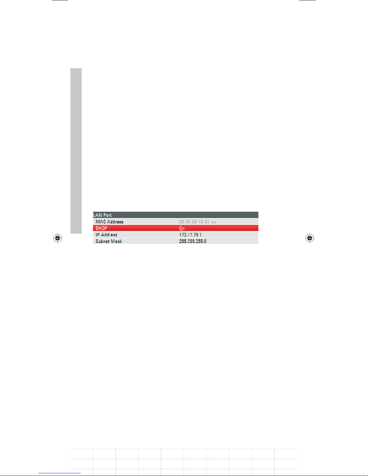
The R&S FSH is now allocated an IP address and
the subnet mask by the DHCP server. This can take
several seconds. The values then appear under
IP ADDRESS and SUBNET MASK under the LAN
PORT heading.
In this example:
IP-address: 172.17.75.1
Subnet mask: 255.255.255.0
The R&S FSH4View software must then be
confi gured as described in the chapter on direct
LAN connection.
The IP address and subnet mask assigned
by the DHCP server must then be used to
create a new LAN connection.
67
2.9.3 Connection via USB
Switch on the R&S FSH.
Connect the R&S FSH directly to the PC with
the USB cable supplied. The R&S FSH USB
interface is situated on the left side under
a protective cap (see also the chapter on
spectrum analyzer connections).
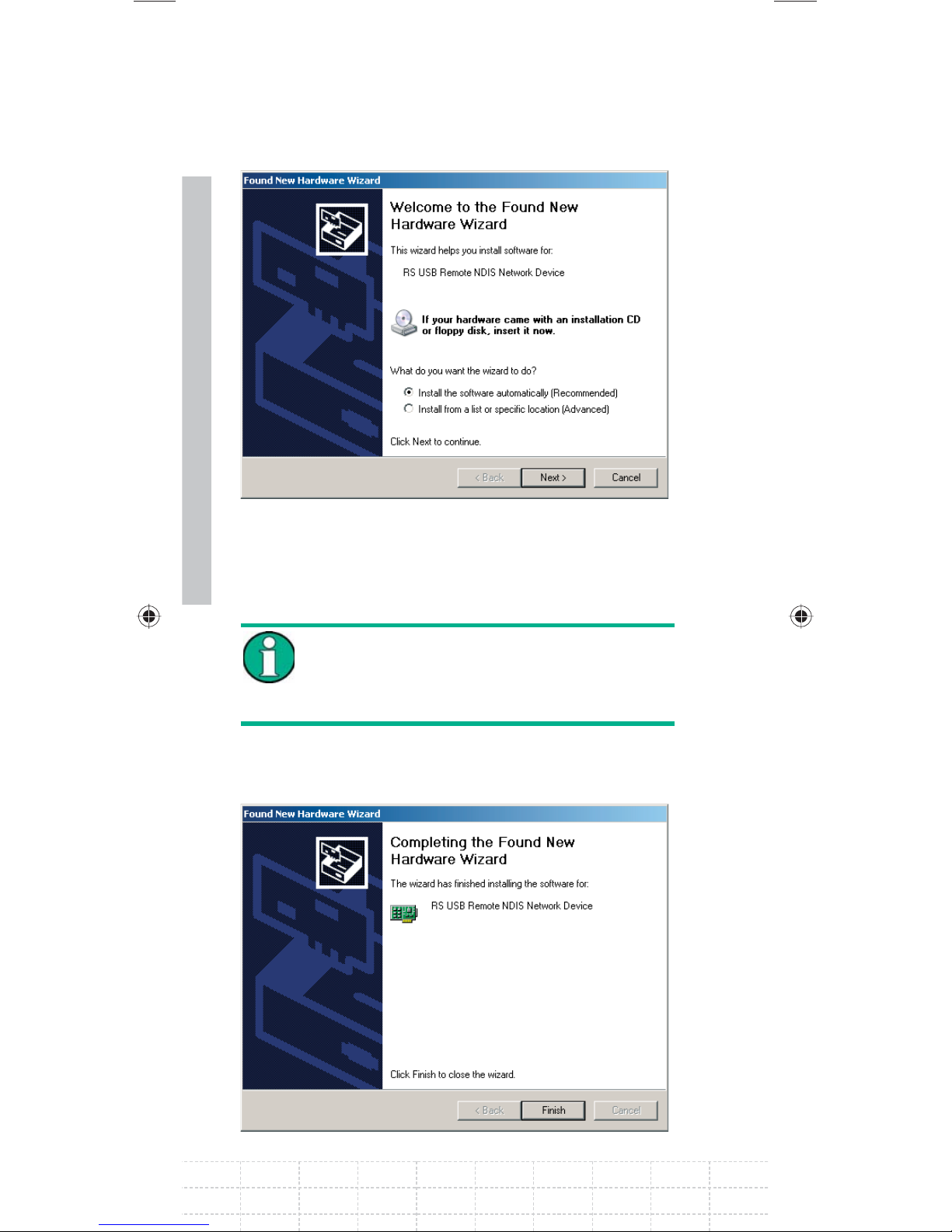
When connected for the fi rst time, the wizard for
fi nding new hardware appears on the PC screen.
E-02
Page 70
68
Select INSTALL THE SOFTWARE
AUTOMATICALLY (RECOMMENDED).
Confi rm with NEXT.
The R&S FSH4View software must be
installed on the PC. Only then can the
hardware wizard fi nd the necessary drivers
for the USB connection.
After a few seconds, the wizard reports that the
software for the new hardware has been installed.
PD 1309.6269.62-02
Page 71
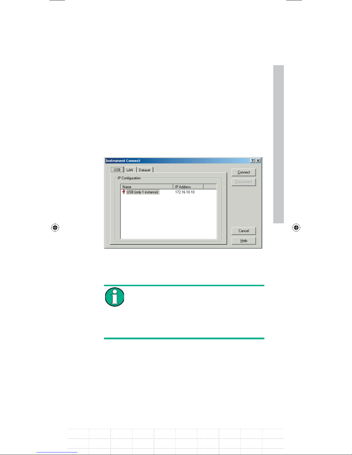
Click FINISH to fi nish the installation.
The connection is now set up.
Open the R&S FSH4View software on the PC.
The INSTRUMENT CONNECT dialog opens.
Select the USB tab in the INSTRUMENT
CONNECT dialog.
69
Select the R&S FSH4 connection.
Click CONNECT.
The FSH internally emulates a LAN
connection. The IP address displayed by
FSH4View for the USB connection is for
information only. It is fi xed to 172.16.10.10
and cannot be changed in FSH4View or the
instrument.
E-02
Page 72

70
PD 1309.6269.62-02
Page 73

3
This section explains the basic operation of the
Handheld Spectrum Analyzer R&S FSH using
some simple measurements as examples. A more
detailed description of operation and functions,
such as selecting menus and setting measurement
parameters, is given in section 3 of the manual on
the CD-ROM.
Getting started
3.1 Controlling the RF Attenuator
Depending on the selected reference level, the
R&S FSH sets the attenuator on the RF input to
a suitable value. It offers two modes: one for the
highest possible sensitivity (AUTO LOW NOISE)
and one for the lowest possible intermodulation
products (AUTO LOW DISTORTION). The difference
between the two modes is that the attenuation that
the R&S FSH sets for the RF attenuator is 5 to 10 dB
higher for AUTO LOW DISTORTION than for AUTO
LOW NOISE. The default setting is AUTO LOW
DISTORTION. The table in the chapter on working
with a pre-amplifi er shows the setting for the RF
attenuator as a function of the reference level.
Press the AMPT key.
71
Press the RF ATT/AMP/IMP softkey.
Select the desired AUTO LOW NOISE or AUTO
LOW DISTORTION mode with the rotary knob
or the cursor keys below the RF ATTENUATION
menu item.
E-02
Page 74
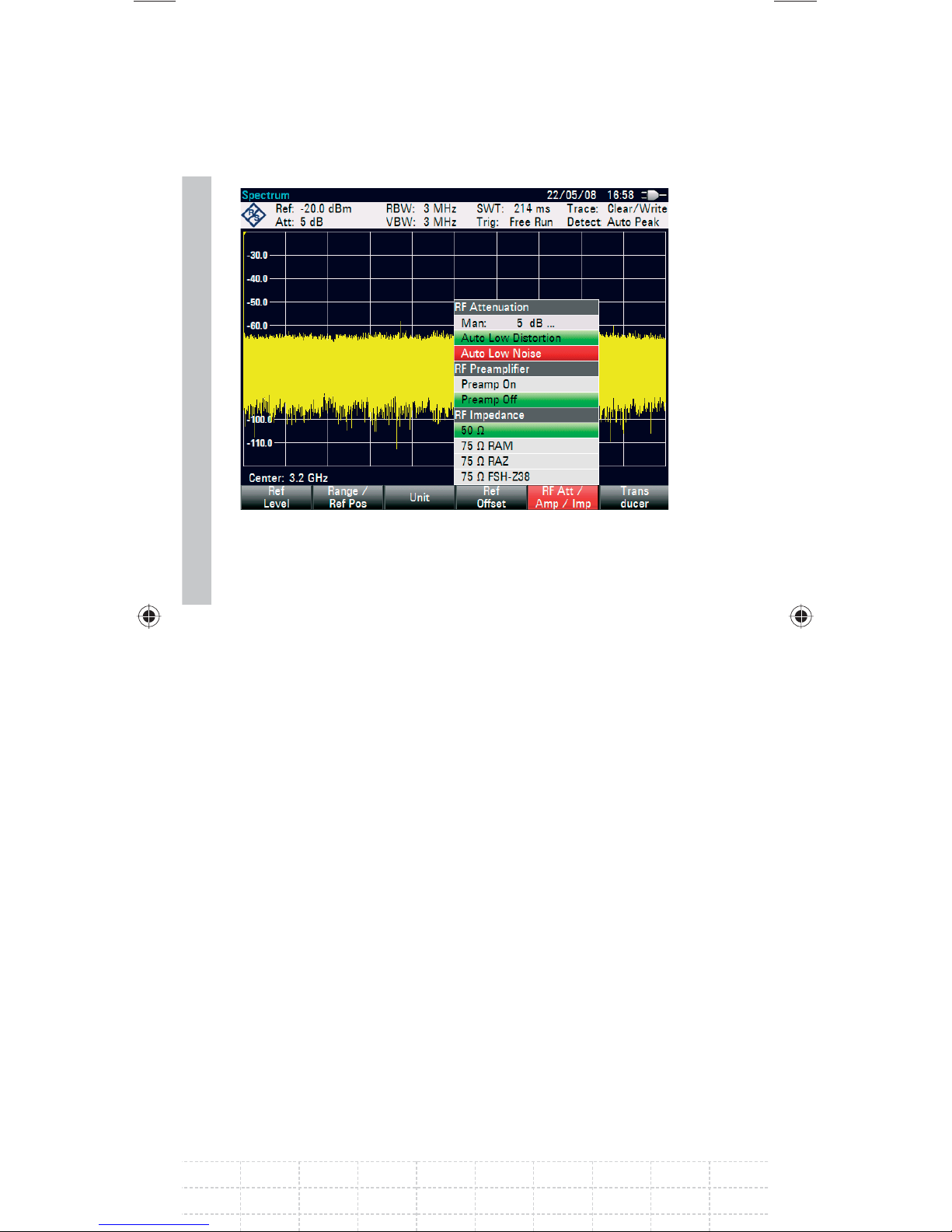
72
Confi rm with ENTER or the RF ATT/AMP/IMP
softkey.
The current attenuation value for the RF attenuator
is displayed in the status bar at the upper edge of
the screen below the Att: caption.
To set the attenuator manually, proceed as follows:
Press the AMPT key.
Press the RF ATT/AMP/IMP softkey.
Select the MAN: sub-item below the
RF ATTENUATION menu item with the rotary
knob or the cursor keys.
Confi rm with ENTER.
PD 1309.6269.62-02
Page 75
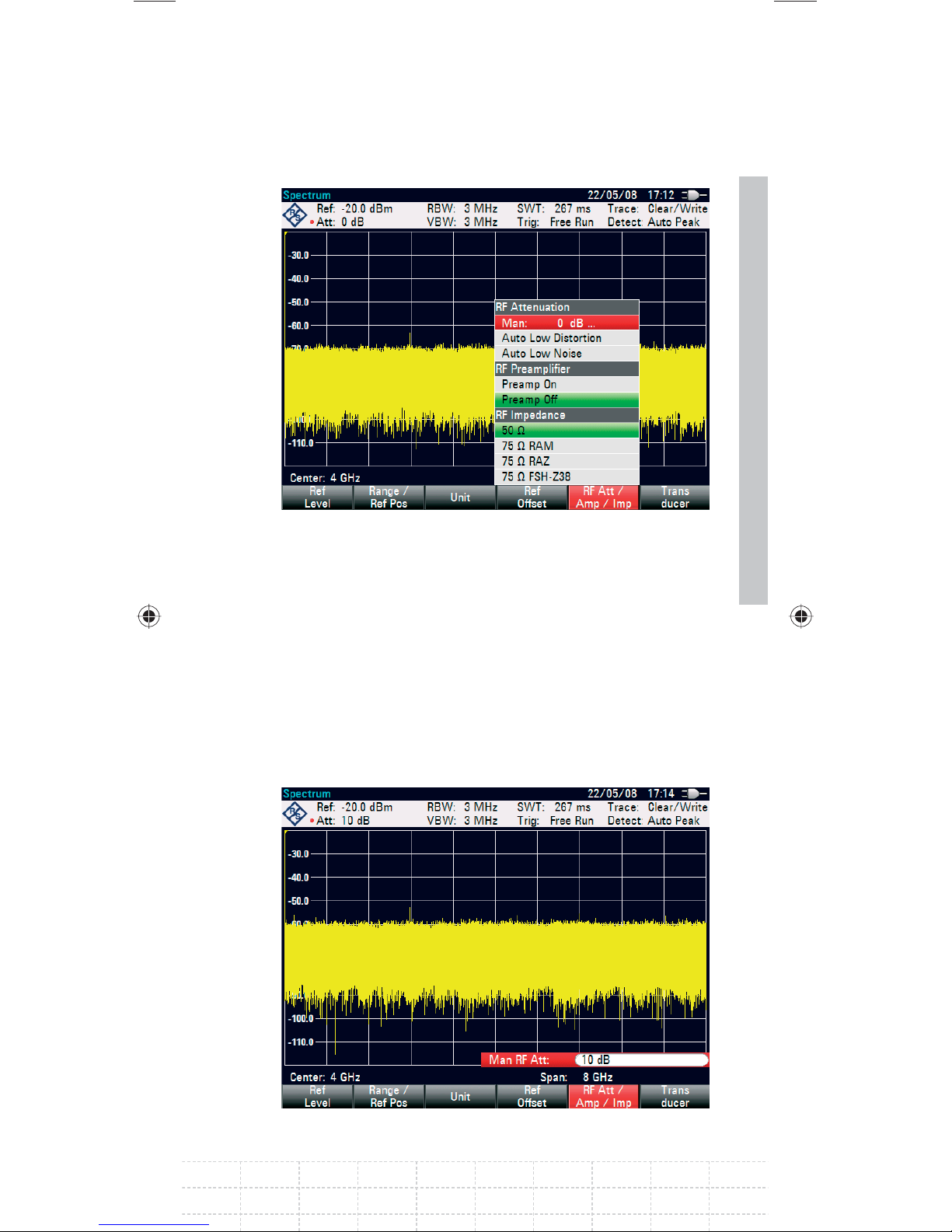
The current attenuation value of the attenuator
is displayed in the input fi eld. This value can be
changed with the rotary knob or the cursor keys
in 5 dB steps within the 0 dB to 40 dB range. The
desired value can also be entered directly via the
numeric keypad.
Confi rm the input of the attenuation value with
ENTER.
73
E-02
Page 76

74
The set damping value for the attenuator is
displayed in the status bar at the upper edge of the
screen behind the Att: caption.
To re-activate automatic attenuator setting as
described, select either AUTO LOW NOISE or AUTO
LOW DISTORTION.
PD 1309.6269.62-02
Page 77
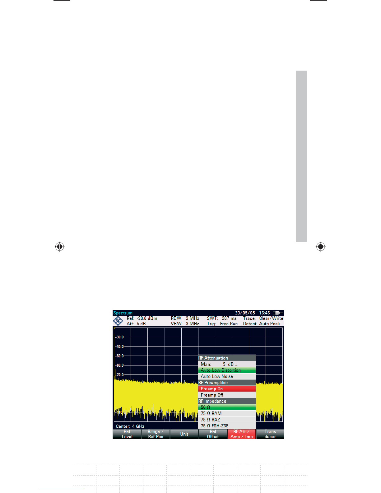
3.2 Using a Preamplifi er
The R&S FSH has an internal preamplifi er
for increasing sensitivity. Depending on the
frequency, this amplifi er has 15 dB to 20 dB gain
and increases sensitivity by 10 to 15 dB. It is fi tted
behind the RF attenuator and in front of the input
mixer.
Press the AMPT key.
Press the RF ATT/AMP/IMP softkey.
The R&S FSH changes to the submenu for
confi guring the pre-amplifi er. The green selection
bar displays the current setting.
Select the desired setting in the RF
PREAMPLIFIER submenu with the rotary
75
knob or the cursor keys (PREAMP ON or
PREAMP OFF).
Confi rm with ENTER or the RF ATT/AMP/IMP
softkey.
E-02
Page 78
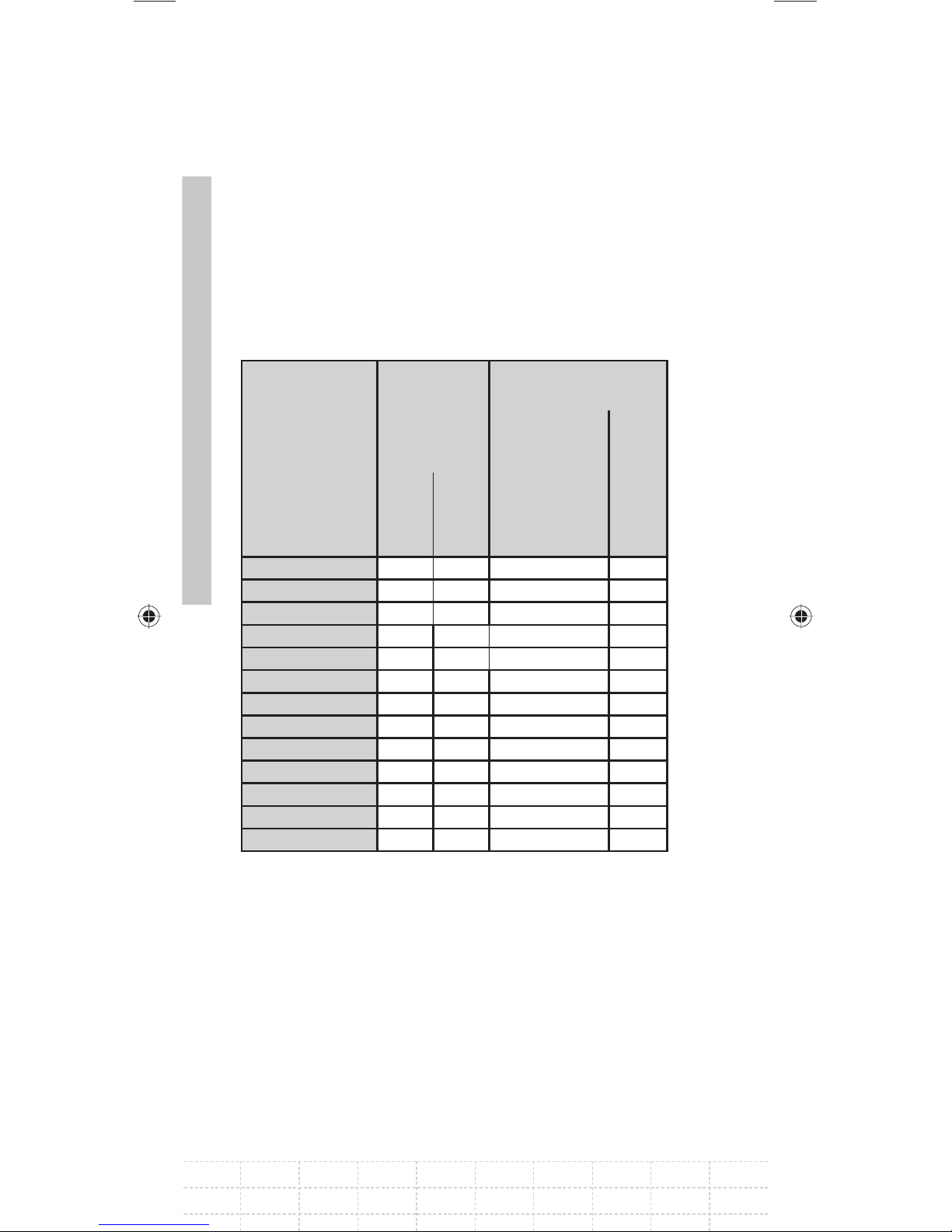
If the preamplifi er is switched on, its use is coupled
to the reference level, thus ensuring the optimum
dynamic range of the R&S FSH at all times.
The table below shows the positions of the RF
attenuator and the preamplifi er as a function of the
reference level.
76
Preamplifi er
OFF
RF attenuation RF attenuation
Reference level
Low Noise
≤ -30 dBm
-29.9 to -25 dBm 0 dB 0 dB 10 dB On
-24.9 to -20 dBm 0 dB 0 dB 5 dB On
-19.9 to -15 dBm 0 dB 5 dB 10 dB On
-14.9 to -10 dBm 0 dB 10 dB 0 dB Off
-9.9 to -5 dBm 5 dB 15 dB 5 dB Off
-4.9 to 0 dBm 10 dB 20 dB 10 dB Off
0.1 to 5 dBm 15 dB 25 dB 15 dB Off
5.1 to 10 dBm 20 dB 30 dB 20 dB Off
10.1 to 15 dBm 25 dB 35 dB 25 dB Off
15.1 to 20 dBm 30 dB 40 dB 30 dB Off
20.1 to 25 dBm 35 dB 40 dB 35 dB Off
25.1 to 30 dBm 40 dB 40 dB 40 dB Off
0 dB 0 dB 0 dB On
Low
Distortion
Preamplifi er
ON
Low Noise
Preamplifi er
PD 1309.6269.62-02
Page 79

3.3 Measurements on CW Signals
A basic task performed by spectrum analyzers is
measuring the level and frequency of sinewave
signals. The following examples illustrate the most
effective way of performing these measurements
with the R&S FSH.
A signal generator is used as a signal source, e.g.
the Signal Generator R&S SML.
Measurement setup
Connect the RF output of the signal generator to
the RF input of the R&S FSH.
Signal generator settings:
Frequency: 700 MHz
Level: -30 dBm
3.3.1 Level Measurement
First, set the R&S FSH to its default settings to
show all the operating steps that are required.
Press the PRESET key.
77
The analyzer displays the frequency spectrum
over the R&S FSH’s maximum frequency span. At
700 MHz, the generator signal is displayed as a
vertical line.
To analyze the generator signal at 700 MHz in
more detail, reduce the frequency span. Set the
R&S FSH’s center frequency to 700 MHz and
reduce the span to 10 MHz.
E-02
Page 80
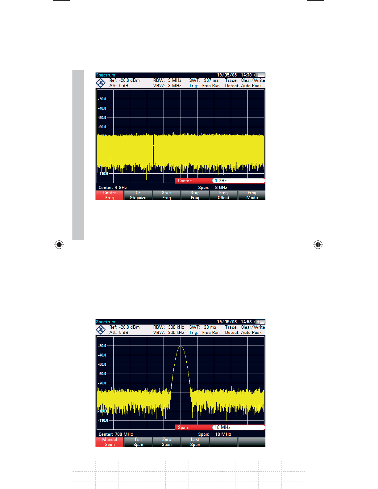
78
Press the FREQ key.
Enter ‘700’ using the numeric keypad and
confi rm the entry with the MHz key.
Press the SPAN key.
Enter ‘10’ using the numeric keypad and
confi rm the entry with the MHz key.
The R&S FSH now displays the generator signal
with a higher resolution.
PD 1309.6269.62-02
Page 81
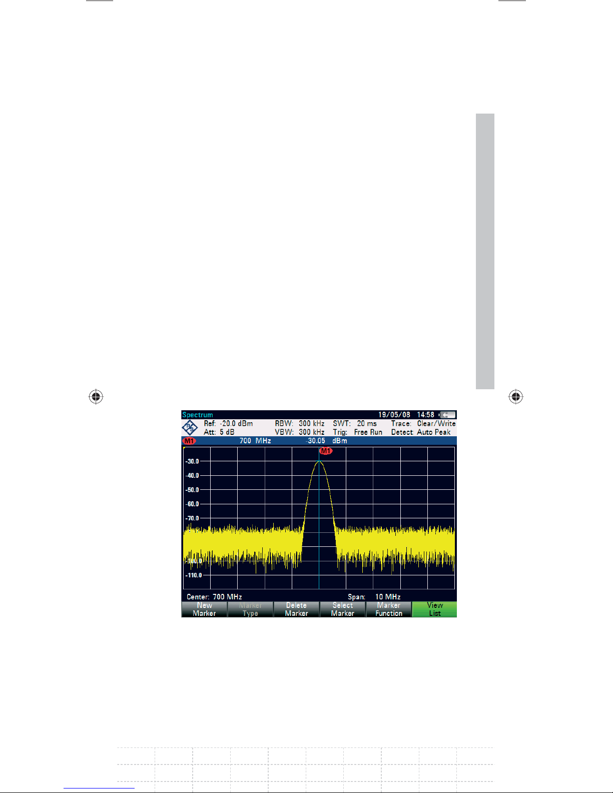
The R&S FSH has markers for reading off signal
levels and frequencies. Markers are always
positioned on the trace. Both the level and
frequency at their current positions are displayed
on the screen.
Press the marker key.
The marker is activated and is automatically
positioned on the trace maximum. A vertical line
on the measurement diagram indicates the marker
frequency. A short horizontal line on the trace
indicates the level.
The R&S FSH displays the level and the frequency
of the marker position numerically above the
measuring screen.
79
E-02
Page 82

80
3.3.2 Setting the Reference Level
The level shown by spectrum analyzers at the
top of the measurement diagram is called the
reference level (REF LEVEL). To obtain the best
dynamic range from a spectrum analyzer, its full
level range should be used. This means that the
maximum spectrum level should be at or close to
the top of the measurement diagram (= reference
level).
The reference level is the maximum level on the
level axis (y axis).
Reduce the reference level by 10 dB to increase the
dynamic range.
Press the AMPT key.
The softkeys for the AMPT menu are displayed
and the REF LEVEL softkey label is highlighted
in red, i.e. it is enabled for value entry. The red
value entry box at the bottom right-hand corner
of the measurement diagram displays the current
reference level.
Enter ‘30’ using the numeric keypad and
confi rm the entry with the ‘-dBm’ key.
The reference level is now set to –30 dBm. The
maximum trace value is close to the maximum
scale value of the measurement diagram. The
increase in the displayed noise fl oor is minimal.
The difference between the signal maximum and
the displayed noise (i.e. the dynamic range) has,
however, been increased.
PD 1309.6269.62-02
Page 83

Using markers is also an effective way to shift
the trace maximum so that it coincides with the
top of the measurement diagram. If the marker
is positioned on the trace maximum (as in the
example), the reference level can be set to the
marker level by entering the following keystrokes:
Press the MARKER-> key.
Press the CENTER=MKR/LEVEL softkey.
Select LEVEL=MARKER LEVEL in the selection
box by using the rotary knob or the cursor keys
(∧ or ∨).
Press the ENTER key.
The reference level is then set to the measured
level indicated by the marker. Only a few
keystrokes are needed to set the optimal reference
81
level.
3.3.3 Frequency Measurements
The R&S FSH’s trace displays 631 measurement
points (frequency points). The marker is always
positioned on one of these measurement points.
The R&S FSH calculates the marker frequency
from the measurement point frequency, and the
center frequency and frequency span that have
been set. The measurement-point resolution, and
consequently the accuracy of the marker frequency
readout, therefore depend on the frequency span
that has been selected.
The R&S FSH has a frequency counter to increase
the accuracy of the marker-frequency readout, It
E-02
Page 84
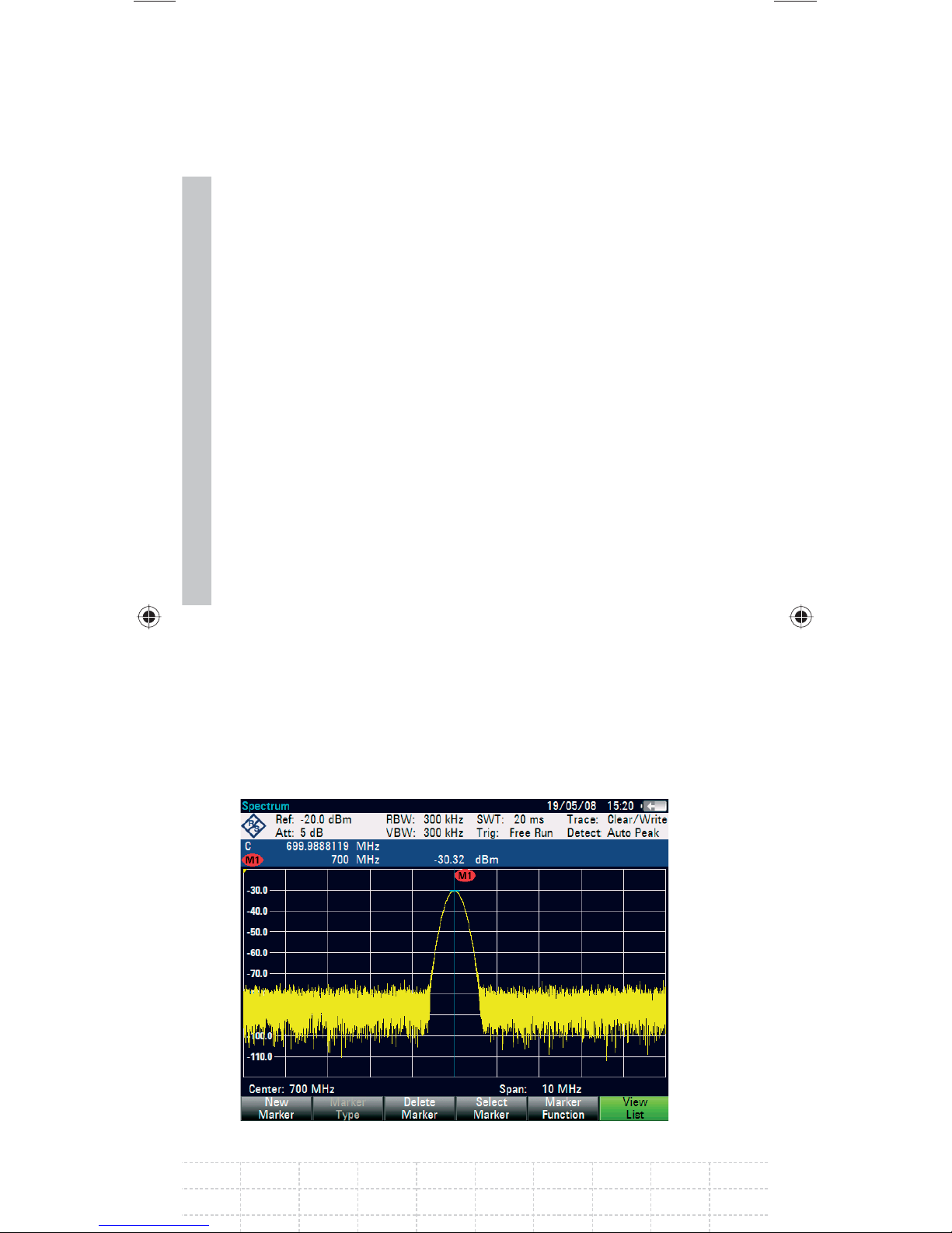
82
stops the sweep at the marker position, counts the
frequency and then continues the sweep.
The following measurement example is based on
the previous example.
Press the MARKER FUNCTION softkey in the
marker menu.
The MARKER FUNCTION selection box opens.
Select FREQUENCY COUNT from the selection
box using the rotary knob or the cursor keys
(∧ or ∨).
Press the ENTER key.
The label ‘M:‘ at the upper left-hand corner of the
measurement diagram changes to ‘C:‘ to tell you
that the frequency counter has been switched
on. The resolution of the frequency readout is
now 1 Hz no matter what span has been set.
The accuracy is determined by the R&S FSH’s
internal reference frequency. It is far higher than
that of pixel-oriented, marker-frequency readout.
PD 1309.6269.62-02
Page 85

3.3.4 Harmonic Measurements of a
Sinewave Signal
Since a spectrum analyzer can resolve different
signals in the frequency domain, it is ideal for
measuring harmonic levels or harmonic ratios.
To speed up these operations, the R&S FSH has
marker functions that deliver fast results with only
a few keystrokes.
As above, a signal generator with a 100 MHz output
frequency and an output level of –20 dBm is used
in the following measurement example.
First, the R&S FSH is set to its default settings to
show all measurement steps that are needed.
Press the PRESET key.
The analyzer displays the frequency spectrum
from the largest available span. At 100 MHz,
the generator signal is displayed as a line. The
generator harmonics are displayed as lines at
frequencies that are multiples of 100 MHz.
To measure the second harmonic ratio, set the start
83
and stop frequency as follows:
Press the FREQ key.
The softkey menu opens entering the frequency.
Press the START FREQ softkey.
Enter '50' using the numeric keypad and
confi rm the entry with the MHz key.
E-02
Page 86
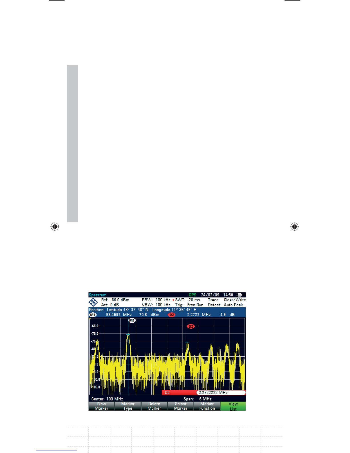
Press the STOP FREQ softkey.
Enter '250' using the numeric keypad and
confi rm the entry with the MHz key.
The R&S FSH now displays the spectrum from
50 MHz to 250 MHz and thus the signal at 100 MHz
and its second harmonic at 200 MHz.
84
To measure the harmonic ratio, set the marker
on the fundamental and the delta marker on the
second harmonic.
Press the MARKER key.
The softkey menu opens for marker entry and
automatically positions the main marker on the
trace maximum.
Press the NEW MARKER softkey.
The delta marker is activated (vertical dotted line)
and is automatically placed on the next trace
maximum (= second harmonic). The harmonic ratio
in dB is displayed at the top of the screen.
PD 1309.6269.62-02
Page 87
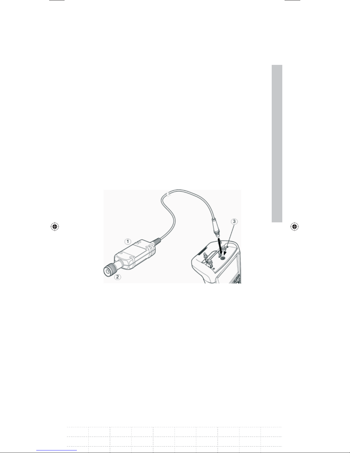
3.4 Power Measurements Using the
Power Sensor
For highly accurate power measurements, the
R&S FSH provides the Power Sensor R&S FSH-Z1
or R&S FSH-Z18 as options. They measure power
in the span 10 MHz to 8 GHz or 10 MHz to 18 GHz,
respectively.
The Power Sensor is controlled and powered
via a special RS-232-C interface at the top of the
instrument.
85
1 Power Sensor R&S FSH-Z1 or R&S FSH-Z18
2 Power Sensor connector (Device under Test)
3 Interface for Power Sensor
E-02
Page 88
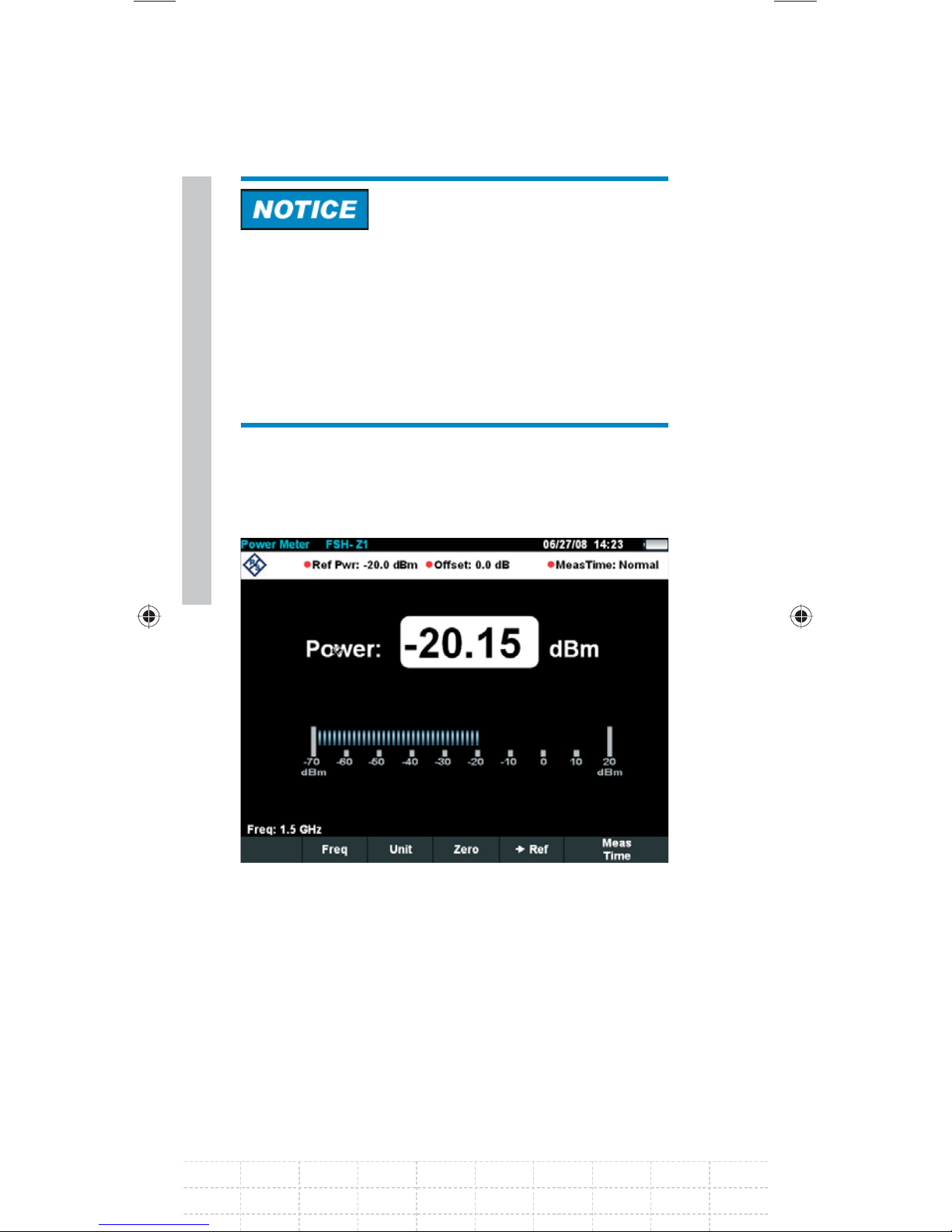
Risk of damage to the sensor due to high input
power
The continuous power applied to the power •
sensor’s input must not exceed 400 mW (26
dBm).
86
Use an attenuator for measurements on high-•
power transmitters.
However, brief (≤10 µs) power peaks up to 1 W
(30 dBm) are permissible.
Connect the power sensor cable to the
R&S FSH’s power sensor connector and screw
into position.
Press the MODE key.
Press the POWER METER softkey.
PD 1309.6269.62-02
Page 89

The R&S FSH changes to power measurement
mode and opens the screen for the power
measurement. If a power sensor has not been
connected, no measured value is displayed. If a
power sensor has been connected, the R&S FSH
sets up a connection via the interface and, after a
few seconds, displays the measured power.
If there are any communication problems with
the power sensor, the R&S FSH outputs error
messages (sensor error: error number) indicating
the possible causes (see main manual).
To compensate for internal offset of the power
meter, it needs to be compensated before starting
the measurement.
Press the ZERO softkey.
The R&S FSH outputs a message telling you not to
apply any signals to the power meter while zeroing
is being performed.
Disconnect the power sensor from any signal
sources.
87
Start zeroing with the softkey CONTINUE.
E-02
Page 90
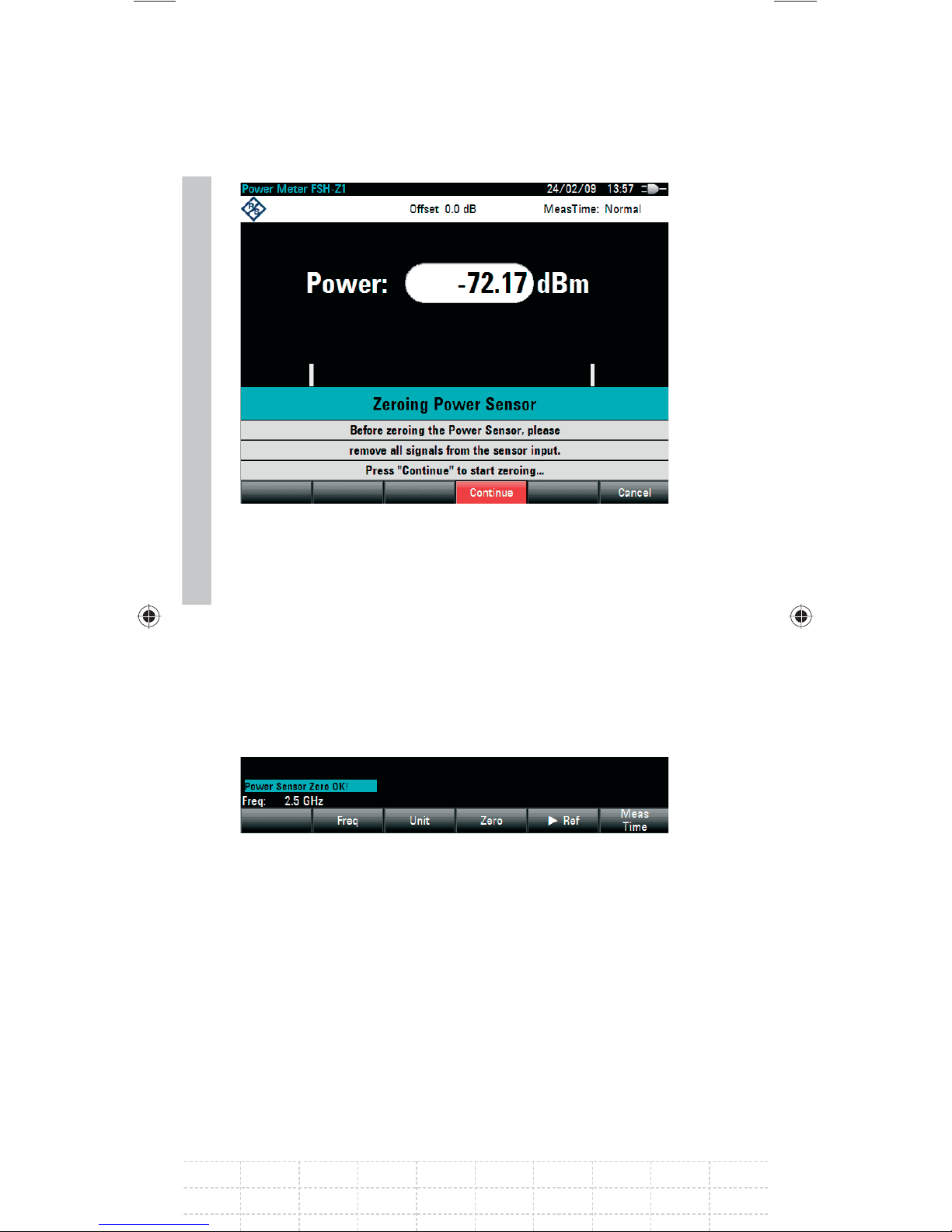
88
The R&S FSH immediately starts power meter
zeroing. While this process is being performed, the
R&S FSH outputs the message “Zeroing power
sensor, please wait...”.
When zeroing is over, the R&S FSH outputs the
message „Power Sensor Zero OK“ and switches
back to the softkey menu for the power sensor.
Connect the signal under test to the
R&S FSH-Z1 or R&S FSH-Z18.
The R&S FSH shows the measured power level in
dBm.
PD 1309.6269.62-02
Page 91

For a highly accurate measurement, enter the
frequency of the signal under test.
Press the FREQ softkey.
Using the numeric keys, enter the frequency
you want and confi rm the entry with the ENTER
key or by pressing the FREQ softkey again.
The R&S FSH transfers the new frequency to the
power sensor which then corrects the measured
power readings.
89
E-02
Page 92
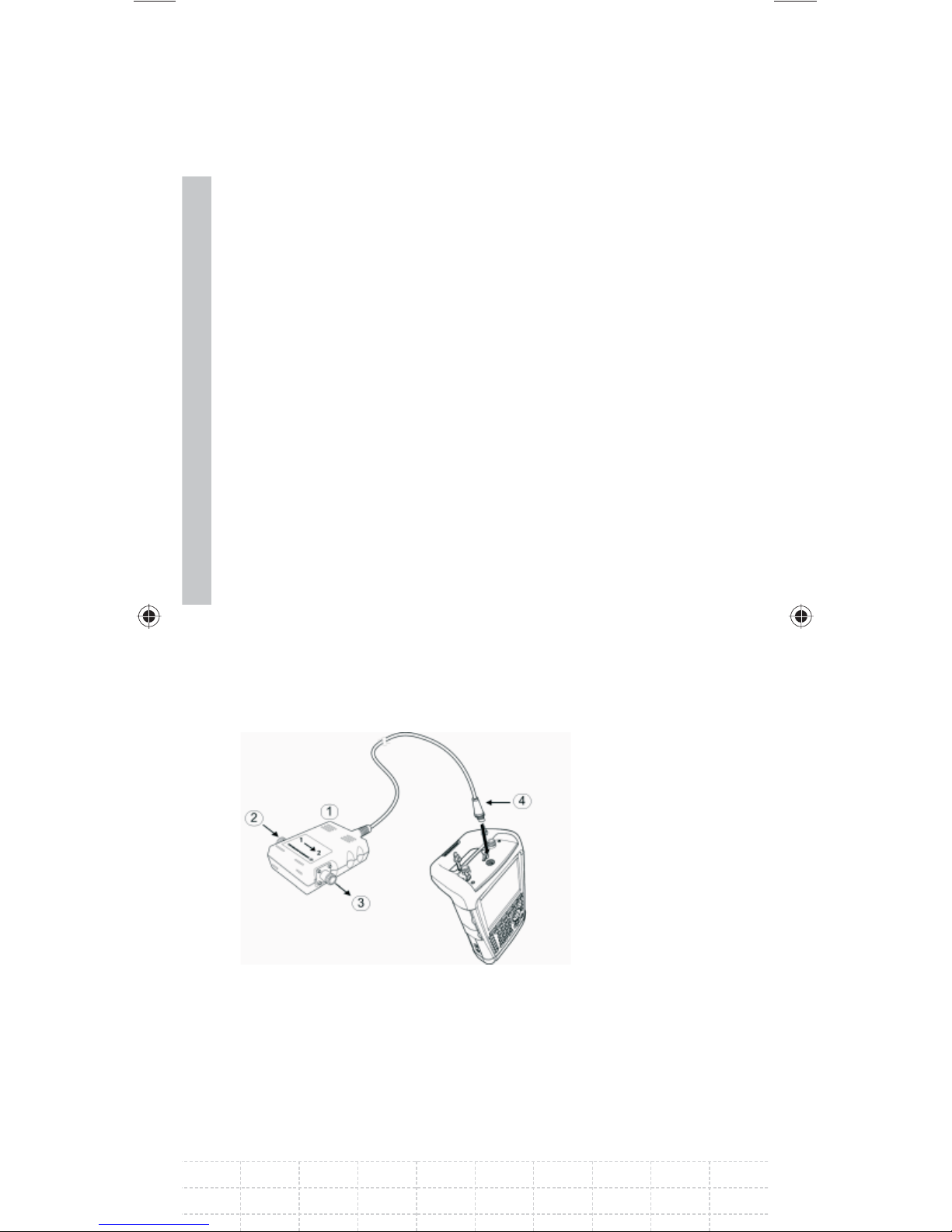
90
3.5 Power and Return Loss
Measurements with the
R&S FSH-Z14 or the R&S FSH-Z44
The Directional Power Sensors R&S FSH-Z14 and
R&S FSH-Z44 are connected between the source
and the load and measure the power fl ux in both
directions, i.e. from the source to the load (forward
power) and from the load to the source (reverse
power). The ratio between reverse power and forward
power is a measure of the load matching and is
displayed as the return loss or standing wave ratio.
The R&S FSH-Z14 and the R&S FSH-Z44 have
an asymmetrical design and must therefore be
inserted into the test setup in such a way that the
FORWARD arrow on the sensor points toward the
load (= in the direction of the power fl ux).
They are driven and powered via a special serial
interface.
1 Directional Power Sensor R&S FSH-Z44
2 Source
3 Load
3 Power sensor socket
PD 1309.6269.62-02
Page 93
When measuring high powers, pay strict attention
to the following instructions to avoid personal
injury and to prevent the power sensor from being
destroyed:
Danger of skin burns and damage to the
instrument
Never exceed the permissible continuous power.•
See diagram on the rear of the sensor for the •
permissible continuous power.
Turn off the RF power to connect the sensor.•
Screw the RF connectors tightly.•
Operation
Connect the cable on the power sensor to
the power sensor socket on the R&S FSH and
screw it on. Insert the directional power sensor
between the source and the load.
Press the MODE key.
Press the POWER METER softkey.
The R&S FSH changes to power measurement
91
mode and opens the screen and the menu for
the directional power measurement. If no power
sensor is connected, no measured value is
displayed. If a power sensor is connected, the
R&S FSH establishes a connection to the power
sensor via the interface and, after a few seconds,
displays the connected power sensor type
(R&S FSH-Z14 or R&S FSH-Z44) as well as the
measured forward power and return loss of the
load.
E-02
Page 94
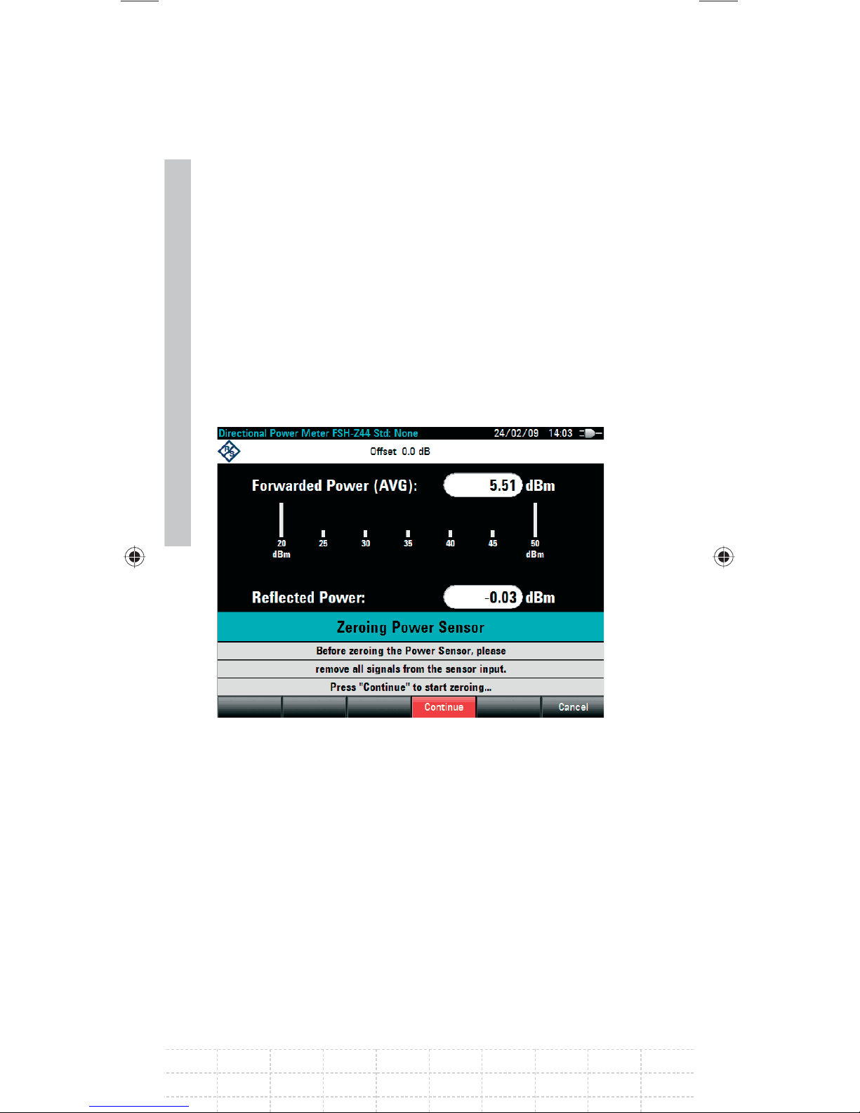
Before performing the power measurement, zero
the power sensor.
Press the ZERO softkey.
The R&S FSH informs you not to apply any signals
while the power sensor is being zeroed.
92
Disconnect the power sensor from any signal
sources.
Start zeroing with the CONTINUE softkey.
The softkey CANCEL can be used to cancel zeroing
before it begins, e.g. if the signal source cannot be
disconnected.
The R&S FSH immediately starts power sensor
zeroing. While this is being done, the R&S FSH
outputs the message “Zeroing power sensor,
please wait...”.
PD 1309.6269.62-02
Page 95
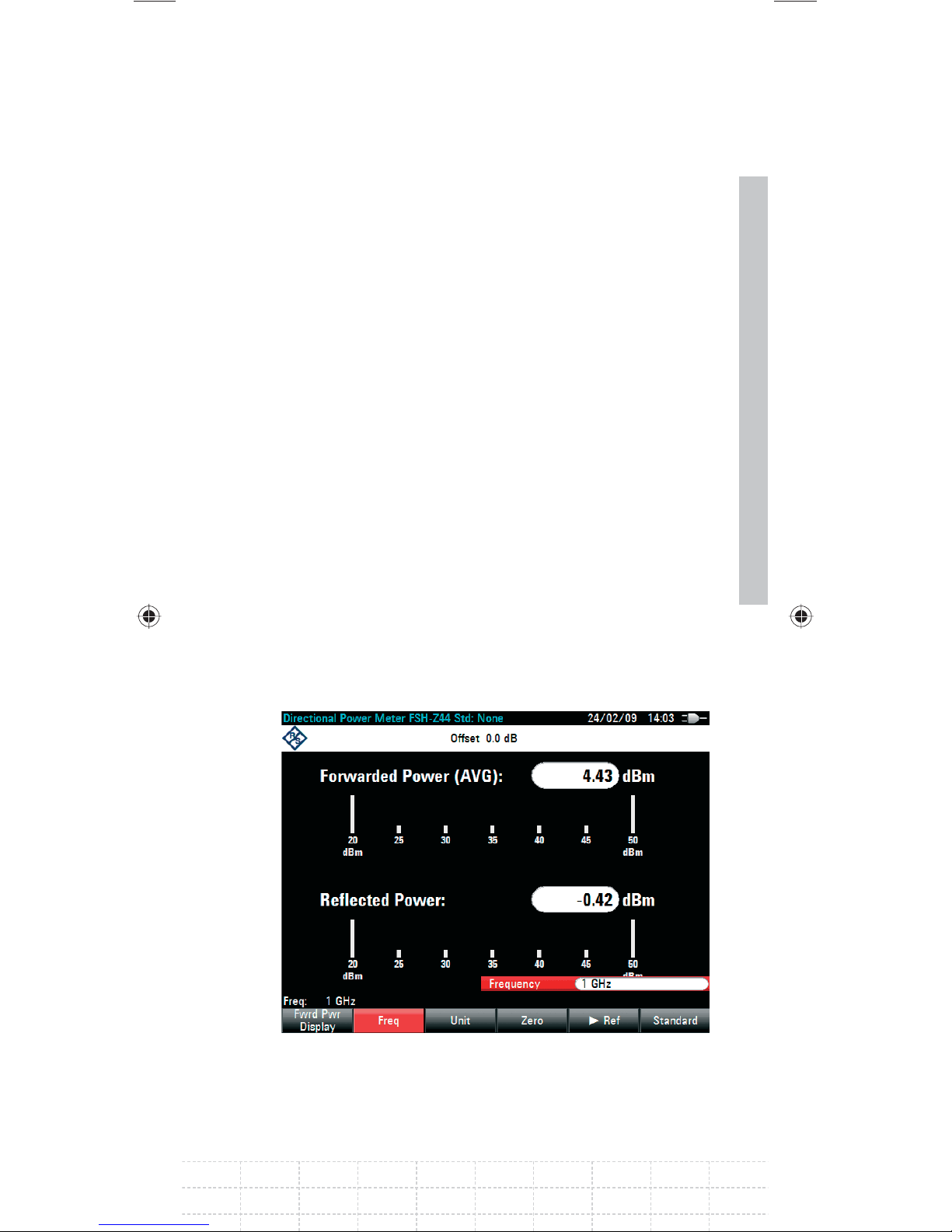
When zeroing is over, the R&S FSH outputs the
message “Power Sensor Zero OK” and switches
back to the softkey menu for the power sensor.
Now connect the R&S FSH-Z14 or R&S FSH-Z44
between the source and the load.
The R&S FSH displays the measured forward
power level in dBm and the VSWR of the load.
To achieve maximum measurement accuracy, enter
the frequency of the signal under test.
Press the FREQ softkey.
The R&S FSH opens the entry box for the frequency.
Enter the desired frequency using the numeric
keys.
Terminate the input with the ENTER key or by
pressing the FREQ softkey again.
93
The R&S FSH transfers the new frequency to the
power sensor which then corrects the measured
power readings.
E-02
Page 96

94
3.6 Measurement of the Transfer
Function of Two-Port Networks
(Only for R&S FSH with tracking generator: order
no. 1309.6000.14, 1309.6000.18, 1309.6000.24 or
1309.6000.28.)
For measurements of the gain or attenuation of
four-port devices, the R&S FSH provides a tracking
generator which generates a sinewave signal
exactly at the receive frequency of the R&S FSH.
For measurements on devices under test which
require an external voltage (e.g. power amplifi ers),
connect the supply of a voltage from a suitable
AC power supply to the appropriate BIAS PORT 1
or BIAS PORT 2 input (for R&S FSH models
1309.6000.24 and 1309.6000.28 only).
Press the MODE key.
Press the NETWORK ANALYZER softkey.
The R&S FSH changes to network analyzer mode
and switches on the tracking generator. Since no
calibration is performed, (UNCAL) is displayed at
the top.
Before calibration, the span you want should be set
because calibration is valid only for the calibrated
span.
Press the FREQ key.
Using the numeric keys, enter the center
frequency.
PD 1309.6269.62-02
Page 97
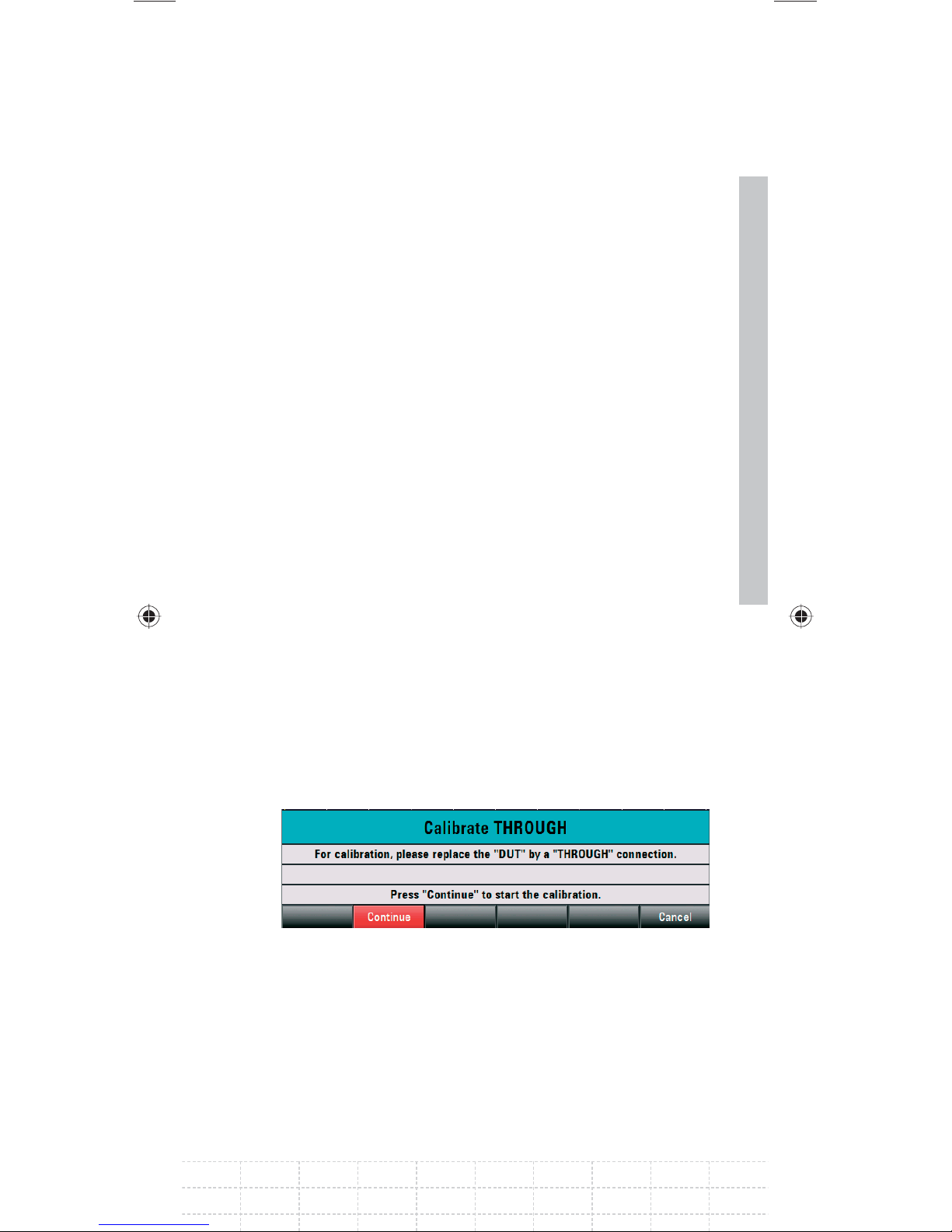
Press the SPAN key.
Using the numeric keys, enter the span.
Alternately, the start and stop frequencies can be
entered using the START FREQ and STOP FREQ
softkeys in the frequency menu.
3.6.1 Calibrating the R&S FSH for Vector
Measurement of the Transmission
Function
(Only for R&S FSH models 1309.6000.24 and
1309.6000.28 with option R&S FSH-K42)
Press the MEAS key.
Press the CALIBRATE softkey.
Select TRANSMISSION FWD (PORT1 -> 2) using
the rotary knob and confi rm with ENTER or the
CALIBRATE softkey.
To calibrate the transfer measurement, the
R&S FSH requests that the RF input be connected
to the tracking generator output.
95
Connect the RF input of the R&S FSH directly to
the tracking generator output without the DUT.
Press the CONTINUE softkey to start calibration.
The R&S FSH then requests to terminate the output
of the tracking generators into 50 Ω (LOAD).
E-02
Page 98
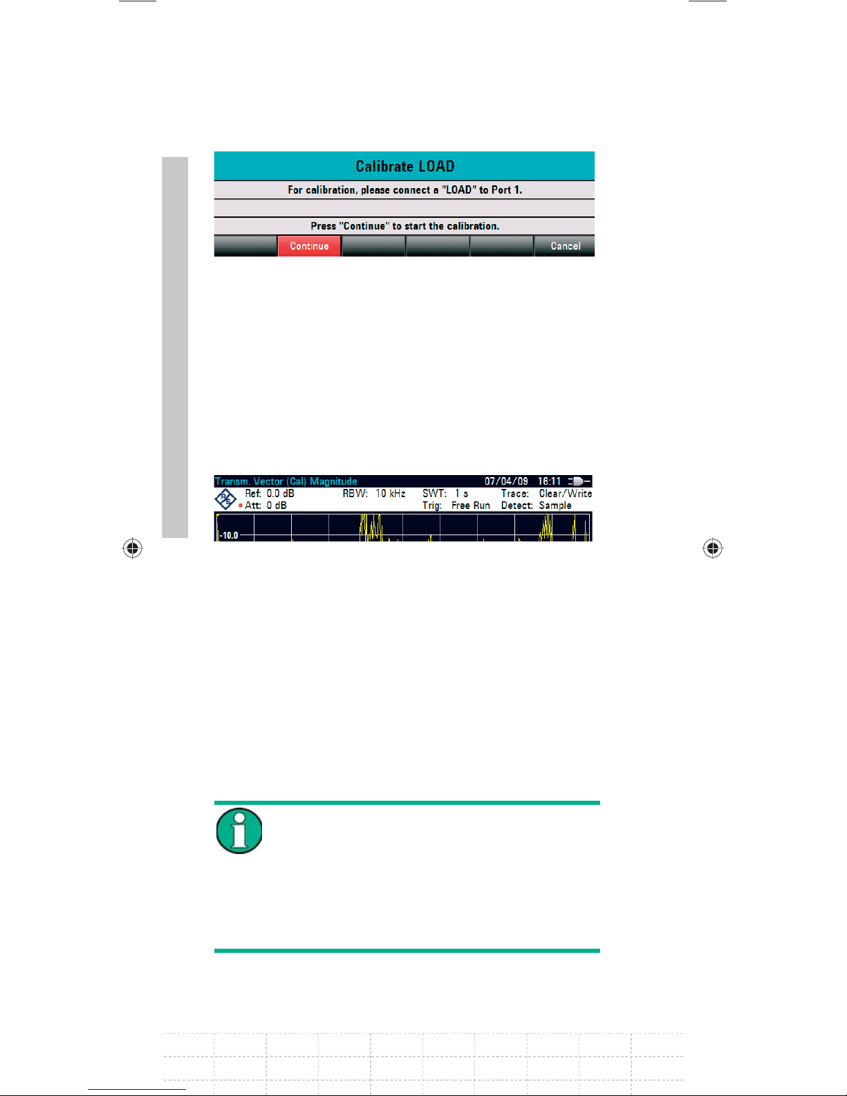
Connect the generator output with the 50 Ω
termination.
96
Press the CONTINUE softkey.
When calibration is over, TRANSM. VECTOR (CAL)
is displayed in the upper area of the screen to
indicate that the R&S FSH is vector-calibrated for
transmission measurement.
3.6.2 Calibrating the R&S FSH for Scalar
Measurement of the Transmission
Function
The following example shows a scalar
measurement of the transmission function. If the
option R&S FSH-K42 is installed, the measurement
must fi rst be switched to scalar (only for R&S FSH
models 1309.6000.24 or 1309.6000.28).
Select VECTOR to increase the accuracy
(for R&S FSH models 1309.6000.24 and
1309.6000.28 with option K42 (vector
network measurements) only). For
R&S FSH models 1309.6000.14 and
1309.6000.18 and without option K42 only
SCALAR can be selected.
PD 1309.6269.62-02
Page 99
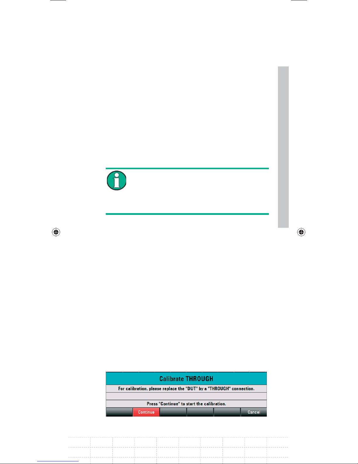
Press the MEAS key.
Press the MEAS MODE softkey.
Using the rotary knob or cursor keys (∧ or ∨),
select SCALAR.
Confi rm with ENTER or the MEAS MODE
softkey.
Press the CALIBRATE softkey in the main menu
for the network analyzer.
With R&S FSH models 1309.6000.24
and 1309.6000.28, the transmission can
be measured in a forward or reverse
direction. With models 1309.6000.14 and
1309.6000.18, in reverse direction only.
Select the desired measurement direction
forward or reverse with the rotary knob or the
cursor keys (∧ or ∨) NORMALIZE TRANSM.
FWD. (PORT 1 -> PORT 2) or NORMALIZE
TRANSM. REV. (PORT 2 -> PORT 1).
Confi rm with ENTER or the CALIBRATE softkey.
The R&S FSH requests that the RF input be
connected to the tracking generator output for
directional calibration.
97
Connect PORT 1 and PORT 2 directly with a
measuring cable without a device under test.
Press CONTINUE to start the calibration.
E-02
Page 100
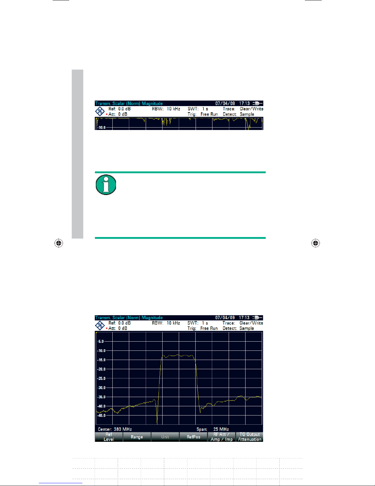
After the calibration is fi nished, the R&S FSH
displays TRANSM. SCALAR (NORM) at the top.
98
3.6.3 Measure the magnitude of the
transfer function
After a two-port calibration it is possible
to switch between forward and reverse
without having to recalibrate the R&S FSH
anew. See also the paragraph on two-port
calibration in the chapter on measuring
the scalar return loss (for R&S FSH models
1309.6000.24 and 1309.6000.28 only).
Connect the DUT between the RF input and the
generator‘s output.
The R&S FSH displays the magnitude of the
transfer function. You can read out values with the
markers, for example.
PD 1309.6269.62-02
 Loading...