

Page 1

2/2006
Page 2

Copyright R&S FS300
0 Copyright
Copyright
© Copyright 2006
ROHDE & SCHWARZ GmbH & Co. KG
Test and Measurement Division
Mühldorfstraße 15
81671 München, Germany
th
13
edition 2/2006
Printed in Germany.
Printed on FFC bleached paper.
Subject to alterations, Errors excepted.
Reprints, also in extracts, are only allowed with written permission of the manufacturer.
All rights reserved.
E-1147.2759.00 0-2 Operating manual, 2/2006
Page 3

R&S FS300 Chapter Overview
Chapter Overview
General
Chapter 1
Chapter 2
Chapter 3
Chapter 4
Chapter 5
Chapter 6
Chapter 7
Chapter 8
Chapter 9
Chapter 10
Content of the Manual for Spectrum Analyzer R&S FS300
Data Sheet
Safety Instructions
Certificate of Quality
EC Certificate of Conformity
Support Center Address
List of Rohde & Schwarz Offices
Introduction
Control Elements
Putting the R&S FS300 into Operation
Getting Started - Measurement Example
Manual Operating Concept
Using the R&S FS300
Remote Control/PC Software FS300-K1
Instrument Interfaces
Error Messages
Index
Operating manual, 2/2006 0-3 E-1147.2759.00
Page 4

Content of the Manual R&S FS300
Content of the Manual
Introduction
This operating manual provides information about:
Technical characteristics of the instrument
Putting into operation
Basic operating procedures and control elements
Operation via menus and remote control
By way of an introduction, a typical R&S FS300 measurement is described.
The operating manual also contains information about maintenance and troubleshooting based on the warnings and error messages issued by the instrument.
E-1147.2759.00 0-4 Operating manual, 2/2006
Page 5

R&S FS300 Table of Contents
Table of Contents
Chapter Overview............................................................................................................................0-3
Content of the Manual..................................................................................................................... 0-4
Table of Contents............................................................................................................................ 0-5
Data Sheet...................................................................................................................................... 0-11
Frequency................................................................................................................................ 0-11
Amplitude................................................................................................................................. 0-12
Inputs ..................................................................................................................................... 0-13
Output ..................................................................................................................................... 0-13
Interfaces ................................................................................................................................. 0-14
Power Supply........................................................................................................................... 0-14
General Data ........................................................................................................................... 0-14
Safety Instructions........................................................................................................................ 0-17
Certificate of Quality.....................................................................................................................0-29
EC Certificate of Conformity........................................................................................................0-30
Support Center Address............................................................................................................... 0-31
List of Rohde & Schwarz Offices.................................................................................................0-32
1 Introduction................................................................................................. 1-38
1.1 Applications for the R&S FS300........................................................................................... 1-38
1.2 Supplied Accessories ........................................................................................................... 1-39
1.3 Warranty ................................................................................................................................. 1-39
2 Control Elements........................................................................................ 2-40
2.1 Front View ..............................................................................................................................2-40
2.2 Rear View................................................................................................................................ 2-41
3 Putting the R&S FS300 into Operation...................................................... 3-42
3.1 Unpacking the R&S FS300.................................................................................................... 3-42
3.2 Setting up the Instrument.....................................................................................................3-42
3.3 Connecting the R&S FS300 to the AC Line......................................................................... 3-44
3.4 Switching On the R&S FS300............................................................................................... 3-44
3.5 Function Test.........................................................................................................................3-45
3.6 EMC......................................................................................................................................... 3-45
3.7 Connecting an External Keyboard....................................................................................... 3-46
3.8 Connecting a USB Stick........................................................................................................ 3-47
4 Getting Started............................................................................................ 4-48
4.1 Level and Frequency Measurements................................................................................... 4-48
Operating manual, 2/2006 0-5 E-1147.2759.00
Page 6

Table of Contents R&S FS300
Measurement Task ...................................................................................................... 4-48
4.1.1
4.1.2 Measurement Procedure ............................................................................................. 4-49
5 Manual Operating Concept ........................................................................ 5-50
5.1 Making Entries from the Keypad.......................................................................................... 5-50
5.1.1 Numerical Keys............................................................................................................ 5-50
5.1.2 Unit Keys...................................................................................................................... 5-50
5.1.3 Rotary Knob ................................................................................................................. 5-51
5.1.4 Cursor Keys ................................................................................................................. 5-51
5.1.5 Function Keys .............................................................................................................. 5-51
5.1.6 Action Keys .................................................................................................................. 5-52
5.1.7 SYS Key....................................................................................................................... 5-52
5.2 Screen Display....................................................................................................................... 5-53
5.2.1 Diagram Area............................................................................................................... 5-54
5.2.2 Menu Area ................................................................................................................... 5-54
5.2.3 Function Area............................................................................................................... 5-55
5.3 Calling and Changing Menus............................................................................................... 5-56
5.4 Setting Parameters................................................................................................................ 5-58
5.4.1 Direct Selection of Instrument Functions..................................................................... 5-58
5.4.2 Selecting Settings ........................................................................................................ 5-59
5.4.3 Entering Numerical Parameters................................................................................... 5-60
5.4.3.1 Entry with the Numerical Keys .................................................................... 5-60
5.4.3.2 Entry using the Cursor Keys and the Rotary Knob ..................................... 5-62
5.5 Overview of all Menus and Functions.................................................................................5-64
5.5.1 Spectrum Analyzer....................................................................................................... 5-64
5.5.1.1 FREQ/SPAN Menu...................................................................................... 5-64
5.5.1.2 AMPT Menu................................................................................................. 5-65
5.5.1.3 MKR Menu................................................................................................... 5-66
5.5.1.4 BW/SWEEP Menu....................................................................................... 5-68
5.5.1.5 TRACE Menu .............................................................................................. 5-69
5.5.1.6 TRIG Menu .................................................................................................. 5-70
5.5.1.7 MEAS Menu ................................................................................................ 5-71
5.5.2 SYSTEM Functions...................................................................................................... 5-72
5.5.2.1 PRESET Menu ............................................................................................ 5-72
5.5.2.2 STATUS Menu ............................................................................................ 5-72
5.5.2.3 FILE Menu ................................................................................................... 5-72
5.5.2.4 CONFIG Menu............................................................................................. 5-72
5.5.2.5 SERVICE Menu........................................................................................... 5-72
5.5.2.6 INFO Menu .................................................................................................. 5-73
6 Using the R&S FS300 ................................................................................. 6-74
6.1 R&S FS300 Factory Settings................................................................................................ 6-74
6.2 Spectrum Analyzer................................................................................................................6-75
6.2.1 Selecting the Frequency Span (FREQ/SPAN Menu) .................................................. 6-76
E-1147.2759.00 0-6 Operating manual, 2/2006
Page 7

R&S FS300 Table of Contents
6.2.1.1
Entering the Center Frequency and the Span............................................. 6-77
6.2.1.2 Entering the Start Frequency and the Stop Frequency............................... 6-78
6.2.1.3 Entering the Step Width of the Center Frequency ...................................... 6-79
6.2.1.3.1 Setting the Step Size ................................................................................ 6-80
6.2.1.4 Frequency-Axis Display Modes................................................................... 6-81
6.2.1.4.1 Displaying the Whole Frequency Range .................................................. 6-82
6.2.1.4.2 Switching over to the ZERO SPAN........................................................... 6-83
6.2.1.4.3 ZOOM Functions....................................................................................... 6-84
6.2.1.5 Signal Tracking............................................................................................ 6-85
6.2.1.5.1 Activating Signal Tracking ........................................................................ 6-86
6.2.2 Setting the Level Axis and the RF Input (AMPT Menu)............................................... 6-87
6.2.2.1 Entering the Reference Level...................................................................... 6-88
6.2.2.2 Entering a Level Offset................................................................................ 6-89
6.2.2.3 Selecting the Level Display Range ............................................................. 6-90
6.2.2.4 Selecting the Level Display Unit.................................................................. 6-91
6.2.2.5 Setting the RF Input Attenuation Manually.................................................. 6-93
6.2.2.6 Setting the RF Input Attenuation Automatically........................................... 6-94
6.2.2.7 Selecting the Setting High Sensitivity.......................................................... 6-96
6.2.3 Signal Analysis using Marker Functions (MKR Menu) ................................................ 6-97
6.2.3.1 Activating Marker 1...................................................................................... 6-98
6.2.3.1.1 Reading off Measured Values with Marker 1............................................ 6-99
6.2.3.1.2 Frequency Measurements using the Frequency Counter ...................... 6-101
6.2.3.2 Activating Marker 2.................................................................................... 6-102
6.2.3.2.1 Reading off Measured Values with Marker 2.......................................... 6-103
6.2.3.2.2 Reading off Level Differences................................................................. 6-104
6.2.3.3 Accepting Marker Values as Settings ....................................................... 6-105
6.2.3.3.1 Moving Trace Sections in the Measurement Diagram ........................... 6-106
6.2.3.3.2 Setting the Step Size to the Marker Frequency...................................... 6-108
6.2.3.4 Marker Measurement Functions ............................................................... 6-109
6.2.3.4.1 Measuring the Noise Power Density ...................................................... 6-110
6.2.3.4.2 Measuring the Filter or Signal Bandwidth............................................... 6-111
6.2.3.5 Activating a Display Line ........................................................................... 6-113
6.2.3.6 Setting the Search Criterion of Functions NEXT PEAK LEFT/RIGHT ...... 6-114
6.2.3.6.1 Entering the Peak Excursion .................................................................. 6-115
6.2.3.7 Setting Reference Points for Level-Difference Measurements................. 6-117
6.2.3.7.1 Manual Entry of Reference Points .......................................................... 6-118
6.2.4 Setting the Bandwidths and the Sweep Time (BW/SWEEP Menu) .......................... 6-121
6.2.4.1 Setting the Resolution Bandwidth ............................................................. 6-122
6.2.4.2 Setting the Video Bandwidth ..................................................................... 6-123
6.2.4.3 RBW, VBW and SPAN Coupling Ratio ..................................................... 6-124
6.2.4.3.1 Changing the Coupling Ratio RBW/VBW ............................................... 6-125
6.2.4.3.2 Switching Over the Coupling RBW/SPAN to Low Noise ........................ 6-126
6.2.4.4 Setting the Sweep ..................................................................................... 6-127
6.2.4.4.1 Selecting the Frequency Sweep ............................................................. 6-128
6.2.4.4.2 Setting the Sweep Time.......................................................................... 6-129
6.2.5 Measured-Value Display (TRACE Menu).................................................................. 6-130
6.2.5.1 Selecting the Active Trace......................................................................... 6-131
6.2.5.1.1 Activating Traces .................................................................................... 6-132
6.2.5.2 Displaying the Active Trace....................................................................... 6-134
6.2.5.3 Trace Difference Function ......................................................................... 6-137
6.2.5.3.1 Activating the Trace Difference Function................................................ 6-138
Operating manual, 2/2006 0-7 E-1147.2759.00
Page 8

Table of Contents R&S FS300
Triggering Measurements (TRIG Menu).................................................................... 6-140
6.2.6
6.2.6.1 Internal Trigger Sources............................................................................ 6-141
6.2.6.2 External Trigger Sources........................................................................... 6-143
6.2.6.2.1 Setting the Trigger Edge for External TTL Signals ................................. 6-144
6.2.6.3 Setting a Trigger Offset ............................................................................. 6-144
6.2.7 Measurement Functions (MEAS Menu) .................................................................... 6-145
6.2.7.1 Measuring the Power in the Time Domain ................................................ 6-146
6.2.7.1.1 Measuring the Power.............................................................................. 6-147
6.2.7.2 Measuring the Third-Order Intercept Point................................................ 6-150
6.3 SYSTEM Functions (SYS Key) ........................................................................................... 6-151
6.3.1 Instrument Default Setting (Menu PRESET) ............................................................. 6-153
6.3.1.1 Selecting and Calling the Instrument Default Setting................................ 6-154
6.3.2 Displaying the Current Instrument Setting (STATUS Menu) .................................... 6-155
6.3.3 User-Defined Settings (FILE Menu) .......................................................................... 6-156
6.3.3.1 Saving and Loading User-Defined Settings .............................................. 6-157
6.3.3.2 Saving and Loading Waveforms ............................................................... 6-159
6.3.3.3 Printing out a Screenshot .......................................................................... 6-161
6.3.4 System Settings (CONFIG Menu) ............................................................................. 6-165
6.3.4.1 Setting the Date and Time of Day ............................................................. 6-166
6.3.4.2 Selecting an Internal or External Reference Source................................. 6-168
6.3.4.3 Configuring the Instrument Interfaces ....................................................... 6-169
6.3.4.4 Setting the Screen Saver Mode ................................................................ 6-171
6.3.4.5 Selecting an Internal or External Monitor .................................................. 6-173
6.3.5 Service Functions (SERVICE Menu) ......................................................................... 6-174
6.3.5.1 Performing Selftests .................................................................................. 6-174
6.3.6 System Information (INFO Menu).............................................................................. 6-175
6.3.6.1 Displaying Module Data ............................................................................ 6-176
6.3.6.2 Displaying Instrument Statistics ................................................................ 6-176
6.3.6.3 Displaying System Messages ................................................................... 6-177
7 Remote Control/PC Software FS300-K1.................................................. 7-179
7.1 Applications of PC Software .............................................................................................. 7-179
7.2 Installation and Configuration............................................................................................ 7-180
7.2.1 Installing the PC Software ......................................................................................... 7-180
7.2.1.1 Installing the Program ............................................................................... 7-180
7.2.1.2 Installing the Device Drivers...................................................................... 7-183
7.2.1.2.1 Installing Steps for Windows™ 2000 ...................................................... 7-183
7.2.1.2.2 Installing Steps for Windows™ XP.......................................................... 7-187
7.2.2 Connecting the PC-Software with the R&S FS300.................................................... 7-192
7.2.2.1 Starting the Series 300 Software Manager ............................................... 7-192
7.2.2.2 Creating the Program Version................................................................... 7-193
7.2.3 Uninstalling the PC Software ..................................................................................... 7-194
7.2.4 Update PC Software .................................................................................................. 7-195
7.3 Starting the Remote Control............................................................................................... 7-197
7.3.1 Connecting the Instrument to the PC......................................................................... 7-197
7.3.2 Starting the Program.................................................................................................. 7-198
E-1147.2759.00 0-8 Operating manual, 2/2006
Page 9

R&S FS300 Table of Contents
Closing the Remote Control....................................................................................... 7-200
7.3.3
7.4 Getting Started.....................................................................................................................7-200
7.4.1 Level and Frequency Measurement .......................................................................... 7-200
7.4.1.1 Measuring Task ......................................................................................... 7-200
7.4.1.2 Measuring Sequence ................................................................................ 7-201
7.5 Control Concept................................................................................................................... 7-203
7.5.1 PC Monitor Display .................................................................................................... 7-203
7.5.1.1 Diagram ..................................................................................................... 7-204
7.5.1.2 Menus........................................................................................................ 7-205
7.5.1.3 Functions ................................................................................................... 7-206
7.5.2 Input via Keyboard and Mouse .................................................................................. 7-207
7.5.2.1 Numeric Keys ............................................................................................ 7-207
7.5.2.2 Arrow Keys ................................................................................................ 7-207
7.5.2.3 Function Keys............................................................................................ 7-208
7.5.2.4 Action Keys (Enter, Esc) ........................................................................... 7-209
7.5.2.5 Tab Key ..................................................................................................... 7-209
7.5.2.6 Space Key ................................................................................................. 7-209
7.5.2.7 Mouse Buttons........................................................................................... 7-210
7.5.3 Calling up and Changing the Menus ......................................................................... 7-211
7.5.4 Setting the Parameters .............................................................................................. 7-212
7.5.4.1 Direct Selection of a Instrument Function ................................................. 7-212
7.5.4.2 Selecting the Settings................................................................................ 7-213
7.5.4.3 Inputting the Numerical Parameters.......................................................... 7-213
7.5.4.4 Moving the Markers................................................................................... 7-215
7.6 Overview of all Menus and Functions (Shortcuts)........................................................... 7-215
7.6.1 File ............................................................................................................................. 7-215
7.6.2 Function ..................................................................................................................... 7-216
7.6.2.1 FREQ Menu............................................................................................... 7-217
7.6.2.2 Amp Menu ................................................................................................. 7-218
7.6.2.3 Marker Menu ............................................................................................. 7-219
7.6.2.4 BW/Sweep Menu....................................................................................... 7-221
7.6.2.5 Trace Menu ............................................................................................... 7-222
7.6.2.6 Trigger Menu ............................................................................................. 7-223
7.6.2.7 Measure Menu........................................................................................... 7-223
7.6.3 View ........................................................................................................................... 7-224
7.6.4 ? Help......................................................................................................................... 7-224
7.6.5 Zoom Functions ........................................................................................................ 7-224
7.7 Saving/Exporting Data (File)............................................................................................... 7-225
7.7.1 Opening the Session ................................................................................................. 7-225
7.7.1.1 Beginning New Measurement ................................................................... 7-225
7.7.1.2 Loading the Saved Settings ...................................................................... 7-226
7.7.2 Saving the Session .................................................................................................... 7-227
7.7.3 Monitoring the Measuring Values .............................................................................. 7-228
7.7.3.1 Inserting the Limit Lines ............................................................................ 7-228
7.7.3.2 Monitoring.................................................................................................. 7-231
Operating manual, 2/2006 0-9 E-1147.2759.00
Page 10

Data Sheet R&S FS300
7.7.3.3
7.7.4 Exporting the Measuring Data ................................................................................... 7-234
7.7.4.1 Creating the ASCII File.............................................................................. 7-234
7.7.4.2 Creating the Screenshot............................................................................ 7-235
7.7.5 Printing the Window ................................................................................................... 7-236
7.8 Customizing the Working Window (View) ........................................................................ 7-237
7.8.1 Adjusting the Window Size ........................................................................................ 7-237
7.8.2 Changing the Window Color ...................................................................................... 7-238
7.9 Getting Help (?)....................................................................................................................7-239
7.9.1 Starting the Help ........................................................................................................ 7-239
7.9.2 Displaying the Program Version ................................................................................ 7-239
7.9.3 Displaying Module Data............................................................................................. 7-240
Analyzing the Logfile ................................................................................. 7-233
8 Instrument Interfaces ............................................................................... 8-241
8.1 Keyboard Connector (KEYB).............................................................................................. 8-241
8.2 Monitor Connector (MON)................................................................................................... 8-241
8.3 Input for External Trigger (EXT TRIG/GATE IN)................................................................ 8-242
8.4 Reference Input and Output (REF IN and REF OUT) .......................................................8-242
8.5 USB Interface (PC, DEV) ..................................................................................................... 8-242
9 Error Messages......................................................................................... 9-243
9.1 System Messages................................................................................................................ 9-243
9.2 Warnings Indicating Impermissible Operating States..................................................... 9-244
10 Index ........................................................................................................ 10-245
E-1147.2759.00 0-10 Operating manual, 2/2006
Page 11

R&S FS300 Data Sheet
Data Sheet
NOTE
For the R&S FS300 a calibration cycle of 1 year is recommended.
Frequency
Frequency range
Reference frequency
Aging
Temperature drift 5 to 30° C
Frequency counter
Resolution
Frequency span
Spectral purity
SSB phase noise 10 kHz offset from carrier < -90 dBc/(1 Hz)
Residual FM 1 kHz resolution bandwidth,
Sweep time
9 kHz to 3 GHz
-6
2•10
/year
-6
1•10
1 Hz, 10 Hz, 100 Hz, 1 kHz
1 kHz to 3 GHz, 0 Hz
< 100 Hz, typ. 60 Hz
1 kHz video bandwidth
SPAN ≥ 1 kHz
SPAN = 0 Hz
100 ms to 1000 s
100 µs to 20 s
Bandwidth
Resolution bandwidths (-3 dB) in 1, 2, 3, 5 steps 200 Hz to 1 MHz
Video bandwidths in 1, 2, 3, 5 steps 10 Hz to 1 MHz, Off
Operating manual, 2/2006 0-11 E-1147.2759.00
Page 12

Data Sheet R&S FS300
Amplitude
Level measurement range
Maximum input level
50 MHz - 3 GHz
10 MHz - 50 MHz
9 kHz - 10 MHz
Intermodulation-free range
1 MHz to 100 MHz
100 MHz to 3 GHz
Harmonic distortion -40 dBm,
Residual spurious input terminated,
Other input related spurious 10 MHz to 3 GHz,
two-tone-signal with
> 137 dB
+33 dBm
+26 dBm
+20 dBm
≤ -60 dBc
2 x -30 dBm at input,
0 dB RF-attenuation
≤ -70 dBc
≤ -60 dBc
0 dB RF-attenuation
≤ -85 dBm
0 dB RF-attenuation
≤ -60 dBc
-30 dBm level at 1
st
mixer
Displayed average noise level 300 Hz resolution bandwidth,
≤ -110 dBm, typ. -120 dBm
10 Hz video bandwidth,
0 dB RF-attenuation
1 dB compression point of 1st mixer 100 kHz to 3 GHz,
-10 dBm
0 dB RF-attenuation
Reference level range
Input attenuation in 2 dB steps, selected manu-
-110 to +36 dBm
0 to 70 dB
ally or automatically coupled to
Display range
reference level
80 dB, 40 dB, 16 dB, 8 dB,
linear
Display units
Logarithmic
Linear
Traces
dBm, dBmV, dBµV
V, W
1 active trace and
1 memory trace
Level uncertainty < 1.5 dB
E-1147.2759.00 0-12 Operating manual, 2/2006
Page 13

R&S FS300 Data Sheet
Markers
Marker
Marker functions
marker and 1 delta marker
peak, next peak, marker to
center, marker to reference
Marker displays
normal, delta, noise marker,
frequency counter
Trigger
free-running, video, external,
line
Inputs
RF Input
Connector
Input impedance
VSWR 10 MHz to 3 GHz,
Max. input power with 30 dB RF-attenuation +33 dBm
Maximum permitted
DC voltage
External trigger input
type N female
50 Ω
< 1.5
RF-attenuation ≥ 20 dB
30 V
Connector
Trigger voltage
External reference input
Connector
Reference frequency
Input voltage
Output
Reference output
Connector
Reference frequency
Output level
BNC female
TTL-voltages
BNC female
10 MHz ± 50 Hz
0.5 to 2 V into 50 Ω
BNC female
10 MHz
> 0.5 V into 50 Ω
Operating manual, 2/2006 0-13 E-1147.2759.00
Page 14

Data Sheet R&S FS300
Interfaces
USB Host
Connector
USB protocol
Command set instrument specific command set, software driver for Windows
USB Device
Connector
USB protocol
(Windows 2000/XP™)
type “A-Plug”
version 1.1
type “B-Plug”
version 1.1
Power Supply
AC supply
Power consumption
100 to 240 V (AC),
50 to 60 Hz, autoranging
< 35 VA
General Data
Display
Type
Resolution
Memory
Trace storage
Setup storage
Environmental conditions
Operating temperature range meets DIN EN 60068-2-1/2 +5 to +45° C
Storage temperature range
Climatic humidity meets DIN EN 60068-2-78
(non condensing)
5.4” active color TFT-display
320 x 240 pixel
5
10
-20 to +70° C
95 % at +40° C
E-1147.2759.00 0-14 Operating manual, 2/2006
Page 15

R&S FS300 Data Sheet
Mechanical resistance
Sinus meets DIN EN 60068-2-6,
DIN EN 61010-1 and
MIL-T-28800D class 5
5 to 150 Hz, max. 2g at 55 Hz,
55 to 150 Hz, 0.5g const.
Random meets DIN EN 60068-2-64 10 to 500 Hz, 1.9g
Shock meets DIN EN 60068-2-27 and
shock spectrum
MIL STD 810
Electromagnetic compatibility
meets EN 55011 class B and EN 61326
(EMC directive 89/336/EEC)
Radiated susceptibility
Safety
Dimensions (W x H x D)
DIN EN 61010-1/IEC61010-1 UL3111-1; CSA22.2 No:1010.1
< 10 V/m
219 mm x 147 mm x 350 mm
(8.6 in x 5.8 in x 13.8 in)
Weight
approx. 7.4 kg
Operating manual, 2/2006 0-15 E-1147.2759.00
Page 16

Page 17

Before putting the product into operation for
the first time, make sure to read the following
Safety Instructions
Rohde & Schwarz makes every effort to keep the safety standard of its products up to
date and to offer its customers the highest possible degree of safety. Our products
and the auxiliary equipment required for them are designed and tested in accordance
with the relevant safety standards. Compliance with these standards is continuously
monitored by our quality assurance system. This product has been designed and
tested in accordance with the EC Certificate of Conformity and has left the
manufacturer’s plant in a condition fully complying with safety standards. To maintain
this condition and to ensure safe operation, observe all instructions and warnings
provided in this manual. If you have any questions regarding these safety instructions,
Rohde & Schwarz will be happy to answer them.
Furthermore, it is your responsibility to use the product in an appropriate manner. This
product is designed for use solely in industrial and laboratory environments or in the
field and must not be used in any way that may cause personal injury or property
damage. You are responsible if the product is used for an intention other than its
designated purpose or in disregard of the manufacturer's instructions. The
manufacturer shall assume no responsibility for such use of the product.
The product is used for its designated purpose if it is used in accordance with its
operating manual and within its performance limits (see data sheet, documentation,
the following safety instructions). Using the products requires technical skills and
knowledge of English. It is therefore essential that the products be used exclusively by
skilled and specialized staff or thoroughly trained personnel with the required skills. If
personal safety gear is required for using Rohde & Schwarz products, this will be
indicated at the appropriate place in the product documentation.
Symbols and safety labels
Observe
operating
instructions
Weight
indication for
units >18 kg
Danger of
electric
shock
Warning!
Hot
surface
PE
terminal
Ground
Ground
terminal
Attention!
Electrostatic
sensitive
devices
Supply
voltage
ON/OFF
1171.0000.52-02.00 Sheet 1
Standby
indication
Direct
current
(DC)
Alternating
current
(AC)
Direct/alternating
current (DC/AC)
Device fully
protected by
double/reinforced
insulation
Page 18

Safety Instructions
Observing the safety instructions will help prevent personal injury or damage of any
kind caused by dangerous situations. Therefore, carefully read through and adhere to
the following safety instructions before putting the product into operation. It is also
absolutely essential to observe the additional safety instructions on personal safety
that appear in other parts of the documentation. In these safety instructions, the word
"product" refers to all merchandise sold and distributed by Rohde & Schwarz,
including instruments, systems and all accessories.
Tags and their meaning
DANGER This tag indicates a safety hazard with a high potential of risk for the
user that can result in death or serious injuries.
WARNING This tag indicates a safety hazard with a medium potential of risk for
the user that can result in death or serious injuries.
CAUTION This tag indicates a safety hazard with a low potential of risk for the
user that can result in slight or minor injuries.
ATTENTION This tag indicates the possibility of incorrect use that can cause
damage to the product.
NOTE This tag indicates a situation where the user should pay special
attention to operating the product but which does not lead to damage.
These tags are in accordance with the standard definition for civil applications in the
European Economic Area. Definitions that deviate from the standard definition may
also exist. It is therefore essential to make sure that the tags described here are
always used only in connection with the associated documentation and the associated
product. The use of tags in connection with unassociated products or unassociated
documentation can result in misinterpretations and thus contribute to personal injury or
material damage.
Basic safety instructions
1. The product may be operated only
under the operating conditions and in
the positions specified by the
manufacturer. Its ventilation must not
be obstructed during operation.
Unless otherwise specified, the
following requirements apply to
Rohde & Schwarz products:
prescribed operating position is
always with the housing floor facing
down, IP protection 2X, pollution
severity 2, overvoltage category 2,
use only in enclosed spaces, max.
operation altitude max. 2000 m.
Unless specified otherwise in the
data sheet, a tolerance of ±10% shall
apply to the nominal voltage and of
±5% to the nominal frequency.
2. Applicable local or national safety
regulations and rules for the
prevention of accidents must be
observed in all work performed. The
product may be opened only by
authorized, specially trained
personnel. Prior to performing any
work on the product or opening the
product, the product must be
disconnected from the supply
network. Any adjustments,
replacements of parts, maintenance
or repair must be carried out only by
technical personnel authorized by
1171.0000.52-02.00 Sheet 2
Page 19

Safety Instructions
Rohde & Schwarz. Only original parts
may be used for replacing parts
relevant to safety (e.g. power
switches, power transformers, fuses).
A safety test must always be
performed after parts relevant to
safety have been replaced (visual
inspection, PE conductor test,
insulation resistance measurement,
leakage current measurement,
functional test).
3. As with all industrially manufactured
goods, the use of substances that
induce an allergic reaction (allergens,
e.g. nickel) such as aluminum cannot
be generally excluded. If you develop
an allergic reaction (such as a skin
rash, frequent sneezing, red eyes or
respiratory difficulties), consult a
physician immediately to determine
the cause.
4. If products/components are
mechanically and/or thermically
processed in a manner that goes
beyond their intended use, hazardous
substances (heavy-metal dust such
as lead, beryllium, nickel) may be
released. For this reason, the product
may only be disassembled, e.g. for
disposal purposes, by specially
trained personnel. Improper
disassembly may be hazardous to
your health. National waste disposal
regulations must be observed.
5. If handling the product yields
hazardous substances or fuels that
must be disposed of in a special way,
e.g. coolants or engine oils that must
be replenished regularly, the safety
instructions of the manufacturer of
the hazardous substances or fuels
and the applicable regional waste
disposal regulations must be
observed. Also observe the relevant
safety instructions in the product
documentation.
6. Depending on the function, certain
products such as RF radio equipment
can produce an elevated level of
electromagnetic radiation.
Considering that unborn life requires
increased protection, pregnant
women should be protected by
appropriate measures. Persons with
pacemakers may also be endangered
by electromagnetic radiation. The
employer is required to assess
workplaces where there is a special
risk of exposure to radiation and, if
necessary, take measures to avert
the danger.
7. Operating the products requires
special training and intense
concentration. Make certain that
persons who use the products are
physically, mentally and emotionally
fit enough to handle operating the
products; otherwise injuries or
material damage may occur. It is the
responsibility of the employer to
select suitable personnel for
operating the products.
8. Prior to switching on the product, it
must be ensured that the nominal
voltage setting on the product
matches the nominal voltage of the
AC supply network. If a different
voltage is to be set, the power fuse of
the product may have to be changed
accordingly.
9. In the case of products of safety class
I with movable power cord and
connector, operation is permitted only
on sockets with earthing contact and
protective earth connection.
10. Intentionally breaking the protective
earth connection either in the feed
line or in the product itself is not
permitted. Doing so can result in the
danger of an electric shock from the
product. If extension cords or
connector strips are implemented,
they must be checked on a regular
basis to ensure that they are safe to
use.
1171.0000.52-02.00 Sheet 3
Page 20

Safety Instructions
11. If the product has no power switch for
disconnection from the AC supply,
the plug of the connecting cable is
regarded as the disconnecting
device. In such cases, it must be
ensured that the power plug is easily
reachable and accessible at all times
(length of connecting cable approx.
2 m). Functional or electronic
switches are not suitable for providing
disconnection from the AC supply. If
products without power switches are
integrated in racks or systems, a
disconnecting device must be
provided at the system level.
12. Never use the product if the power
cable is damaged. By taking
appropriate safety measures and
carefully laying the power cable,
ensure that the cable cannot be
damaged and that no one can be hurt
by e.g. tripping over the cable or
suffering an electric shock.
13. The product may be operated only
from TN/TT supply networks fused
with max. 16 A.
14. Do not insert the plug into sockets
that are dusty or dirty. Insert the plug
firmly and all the way into the socket.
Otherwise this can result in sparks,
fire and/or injuries.
15. Do not overload any sockets,
extension cords or connector strips;
doing so can cause fire or electric
shocks.
16. For measurements in circuits with
voltages V
> 30 V, suitable
rms
measures (e.g. appropriate
measuring equipment, fusing, current
limiting, electrical separation,
insulation) should be taken to avoid
any hazards.
17. Ensure that the connections with
information technology equipment
comply with IEC 950/EN 60950.
18. Never remove the cover or part of the
housing while you are operating the
product. This will expose circuits and
components and can lead to injuries,
fire or damage to the product.
19. If a product is to be permanently
installed, the connection between the
PE terminal on site and the product's
PE conductor must be made first
before any other connection is made.
The product may be installed and
connected only by a skilled
electrician.
20. For permanently installed equipment
without built-in fuses, circuit breakers
or similar protective devices, the
supply circuit must be fused in such a
way that suitable protection is
provided for users and products.
21. Do not insert any objects into the
openings in the housing that are not
designed for this purpose. Never pour
any liquids onto or into the housing.
This can cause short circuits inside
the product and/or electric shocks,
fire or injuries.
22. Use suitable overvoltage protection to
ensure that no overvoltage (such as
that caused by a thunderstorm) can
reach the product. Otherwise the
operating personnel will be
endangered by electric shocks.
23. Rohde & Schwarz products are not
protected against penetration of
water, unless otherwise specified
(see also safety instruction 1.). If this
is not taken into account, there exists
the danger of electric shock or
damage to the product, which can
also lead to personal injury.
24. Never use the product under
conditions in which condensation has
formed or can form in or on the
product, e.g. if the product was
moved from a cold to a warm
environment.
1171.0000.52-02.00 Sheet 4
Page 21

Safety Instructions
25. Do not close any slots or openings on
the product, since they are necessary
for ventilation and prevent the
product from overheating. Do not
place the product on soft surfaces
such as sofas or rugs or inside a
closed housing, unless this is well
ventilated.
26. Do not place the product on heatgenerating devices such as radiators
or fan heaters. The temperature of
the environment must not exceed the
maximum temperature specified in
the data sheet.
27. Batteries and storage batteries must
not be exposed to high temperatures
or fire. Keep batteries and storage
batteries away from children. If
batteries or storage batteries are
improperly replaced, this can cause
an explosion (warning: lithium cells).
Replace the battery or storage
battery only with the matching Rohde
& Schwarz type (see spare parts list).
Batteries and storage batteries are
hazardous waste. Dispose of them
only in specially marked containers.
Observe local regulations regarding
waste disposal. Do not short-circuit
batteries or storage batteries.
28. Please be aware that in the event of
a fire, toxic substances (gases,
liquids etc.) that may be hazardous to
your health may escape from the
product.
29. Please be aware of the weight of the
product. Be careful when moving it;
otherwise you may injure your back
or other parts of your body.
30. Do not place the product on surfaces,
vehicles, cabinets or tables that for
reasons of weight or stability are
unsuitable for this purpose. Always
follow the manufacturer's installation
instructions when installing the
product and fastening it to objects or
structures (e.g. walls and shelves).
31. Handles on the products are
designed exclusively for personnel to
hold or carry the product. It is
therefore not permissible to use
handles for fastening the product to
or on means of transport such as
cranes, fork lifts, wagons, etc. The
user is responsible for securely
fastening the products to or on the
means of transport and for observing
the safety regulations of the
manufacturer of the means of
transport. Noncompliance can result
in personal injury or material damage.
32. If you use the product in a vehicle, it
is the sole responsibility of the driver
to drive the vehicle safely.
Adequately secure the product in the
vehicle to prevent injuries or other
damage in the event of an accident.
Never use the product in a moving
vehicle if doing so could distract the
driver of the vehicle. The driver is
always responsible for the safety of
the vehicle; the manufacturer
assumes no responsibility for
accidents or collisions.
33. If a laser product (e.g. a CD/DVD
drive) is integrated in a Rohde &
Schwarz product, do not use any
other settings or functions than those
described in the documentation.
Otherwise this may be hazardous to
your health, since the laser beam can
cause irreversible damage to your
eyes. Never try to take such products
apart, and never look into the laser
beam.
1171.0000.52-02.00 Sheet 5
Page 22

Informaciones de seguridad
Por favor lea imprescindiblemente antes de
la primera puesta en funcionamiento las
siguientes informaciones de seguridad
Informaciones de seguridad
Es el principio de Rohde & Schwarz de tener a sus productos siempre al día con los
estandards de seguridad y de ofrecer a sus clientes el máximo grado de seguridad.
Nuestros productos y todos los equipos adicionales son siempre fabricados y
examinados según las normas de seguridad vigentes. Nuestra sección de gestión de
la seguridad de calidad controla constantemente que sean cumplidas estas normas.
Este producto ha sido fabricado y examinado según el comprobante de conformidad
adjunto según las normas de la CE y ha salido de nuestra planta en estado impecable
según los estandards técnicos de seguridad. Para poder preservar este estado y
garantizar un funcionamiento libre de peligros, deberá el usuario atenerse a todas las
informaciones, informaciones de seguridad y notas de alerta. Rohde&Schwarz está
siempre a su disposición en caso de que tengan preguntas referentes a estas
informaciones de seguridad.
Además queda en la responsabilidad del usuario utilizar el producto en la forma
debida. Este producto solamente fue elaborado para ser utilizado en la indústria y el
laboratorio o para fines de campo y de ninguna manera deberá ser utilizado de modo
que alguna persona/cosa pueda ser dañada. El uso del producto fuera de sus fines
definidos o despreciando las informaciones de seguridad del fabricante queda en la
responsabilidad del usuario. El fabricante no se hace en ninguna forma responsable
de consecuencias a causa del maluso del producto.
Se parte del uso correcto del producto para los fines definidos si el producto es
utilizado dentro de las instrucciones del correspondiente manual del uso y dentro del
margen de rendimiento definido (ver hoja de datos, documentación, informaciones de
seguridad que siguen). El uso de los productos hace necesarios conocimientos
profundos y el conocimiento del idioma inglés. Por eso se deberá tener en cuenta de
exclusivamente autorizar para el uso de los productos a personas péritas o
debidamente minuciosamente instruidas con los conocimientos citados. Si fuera
necesaria indumentaria de seguridad para el uso de productos de R&S, encontrará la
información debida en la documentación del producto en el capítulo correspondiente.
1171.0000.52-02.00 Sheet 6
Page 23

Informaciones de seguridad
Símbolos y definiciones de seguridad
Ver
manual de
instruccion
es del uso
Informaciones
para
maquinaria
con uns peso
de > 18kg
Peligro
de golpe
de
corriente
¡Advertencia!
Superficie
caliente
Conexión
a
conductor
protector
Conexión
a tierra
Conexión
a masa
conductora
¡Cuidado!
Elementos de
construción
con peligro de
carga
electroestática
potencia EN
MARCHA/PARADA
Indicación
Stand-by
Corriente
continua
DC
Corriente
alterna
AC
Corriente
continua/alterna
DC/AC
El aparato está protegido
en su totalidad por un
aislamiento de doble
refuerzo
Tener en cuenta las informaciones de seguridad sirve para tratar de evitar daños y
peligros de toda clase. Es necesario de que se lean las siguientes informaciones de
seguridad concienzudamente y se tengan en cuenta debidamente antes de la puesta
en funcionamiento del producto. También deberán ser tenidas en cuenta las
informaciones para la protección de personas que encontrarán en otro capítulo de
esta documentación y que también son obligatorias de seguir. En las informaciones
de seguridad actuales hemos juntado todos los objetos vendidos por Rohde&Schwarz
bajo la denominación de „producto“, entre ellos también aparatos, instalaciones así
como toda clase de accesorios.
Palabras de señal y su significado
PELIGRO Indica un punto de peligro con gran potencial de riesgo para el
ususario.Punto de peligro que puede llevar hasta la muerte o
graves heridas.
ADVERTENCIA Indica un punto de peligro con un protencial de riesgo mediano
para el usuario. Punto de peligro que puede llevar hasta la muerte
o graves heridas .
ATENCIÓN Indica un punto de peligro con un protencial de riesgo pequeño
para el usuario. Punto de peligro que puede llevar hasta heridas
leves o pequeñas
CUIDADO Indica la posibilidad de utilizar mal el producto y a consecuencia
dañarlo.
INFORMACIÓN Indica una situación en la que deberían seguirse las instrucciones
en el uso del producto, pero que no consecuentemente deben de
llevar a un daño del mismo.
1171.0000.52-02.00 Sheet 7
Page 24

Informaciones de seguridad
Las palabras de señal corresponden a la definición habitual para aplicaciones civiles
en el ámbito de la comunidad económica europea. Pueden existir definiciones
diferentes a esta definición. Por eso se debera tener en cuenta que las palabras de
señal aquí descritas sean utilizadas siempre solamente en combinación con la
correspondiente documentación y solamente en combinación con el producto
correspondiente. La utilización de las palabras de señal en combinación con
productos o documentaciones que no les correspondan puede llevar a
malinterpretaciones y tener por consecuencia daños en personas u objetos.
Informaciones de seguridad elementales
1. El producto solamente debe ser
utilizado según lo indicado por el
fabricante referente a la situación y
posición de funcionamiento sin que
se obstruya la ventilación. Si no se
convino de otra manera, es para los
productos R&S válido lo que sigue:
como posición de funcionamiento se
define principialmente la posición con
el suelo de la caja para abajo , modo
de protección IP 2X, grado de
suciedad 2, categoría de sobrecarga
eléctrica 2, utilizar solamente en
estancias interiores, utilización hasta
2000 m sobre el nivel del mar.
A menos que se especifique otra
cosa en la hoja de datos, se aplicará
una tolerancia de ±10% sobre el
voltaje nominal y de ±5% sobre la
frecuencia nominal.
2. En todos los trabajos deberán ser
tenidas en cuenta las normas locales
de seguridad de trabajo y de
prevención de accidentes. El
producto solamente debe de ser
abierto por personal périto
autorizado. Antes de efectuar
trabajos en el producto o abrirlo
deberá este ser desconectado de la
corriente. El ajuste, el cambio de
partes, la manutención y la
reparación deberán ser solamente
efectuadas por electricistas
autorizados por R&S. Si se reponen
partes con importancia para los
aspectos de seguridad (por ejemplo
el enchufe, los transformadores o los
fusibles), solamente podrán ser
sustituidos por partes originales.
Despues de cada recambio de
partes elementales para la seguridad
deberá ser efectuado un control de
seguridad (control a primera vista,
control de conductor protector,
medición de resistencia de
aislamiento, medición de medición de
la corriente conductora, control de
funcionamiento).
3. Como en todo producto de
fabricación industrial no puede ser
excluido en general de que se
produzcan al usarlo elementos que
puedan generar alergias, los
llamados elementos alergénicos (por
ejemplo el níquel). Si se producieran
en el trato con productos R&S
reacciones alérgicas, como por
ejemplo urticaria, estornudos
frecuentes, irritación de la conjuntiva
o dificultades al respirar, se deberá
consultar inmediatamente a un
médico para averigurar los motivos
de estas reacciones.
1171.0000.52-02.00 Sheet 8
Page 25

Informaciones de seguridad
4. Si productos / elementos de
construcción son tratados fuera del
funcionamiento definido de forma
mecánica o térmica, pueden
generarse elementos peligrosos
(polvos de sustancia de metales
pesados como por ejemplo plomo,
berilio, níquel). La partición elemental
del producto, como por ejemplo
sucede en el tratamiento de materias
residuales, debe de ser efectuada
solamente por personal especializado
para estos tratamientos. La partición
elemental efectuada
inadecuadamente puede generar
daños para la salud. Se deben tener
en cuenta las directivas nacionales
referentes al tratamiento de materias
residuales.
5. En el caso de que se produjeran
agentes de peligro o combustibles en
la aplicación del producto que
debieran de ser transferidos a un
tratamiento de materias residuales,
como por ejemplo agentes
refrigerantes que deben ser
repuestos en periodos definidos, o
aceites para motores, deberan ser
tenidas en cuenta las prescripciones
de seguridad del fabricante de estos
agentes de peligro o combustibles y
las regulaciones regionales para el
tratamiento de materias residuales.
Cuiden también de tener en cuenta
en caso dado las prescripciones de
seguridad especiales en la
descripción del producto.
6. Ciertos productos, como por ejemplo
las instalaciones de radiación HF,
pueden a causa de su función
natural, emitir una radiación
electromagnética aumentada. En
vista a la protección de la vida en
desarrollo deberían ser protegidas
personas embarazadas debidamente.
También las personas con un bypass
pueden correr peligro a causa de la
radiación electromagnética. El
empresario está comprometido a
valorar y señalar areas de trabajo en
las que se corra un riesgo de
exposición a radiaciones aumentadas
de riesgo aumentado para evitar
riesgos.
7. La utilización de los productos
requiere instrucciones especiales y
una alta concentración en el manejo.
Debe de ponerse por seguro de que
las personas que manejen los
productos estén a la altura de los
requerimientos necesarios referente
a sus aptitudes físicas, psíquicas y
emocionales, ya que de otra manera
no se pueden excluir lesiones o
daños de objetos. El empresario lleva
la responsabilidad de seleccionar el
personal usuario apto para el manejo
de los productos.
8. Antes de la puesta en marcha del
producto se deberá tener por seguro
de que la tensión preseleccionada en
el producto equivalga a la del la red
de distribución. Si es necesario
cambiar la preselección de la tensión
también se deberán en caso dabo
cambiar los fusibles correspondientes
del prodcuto.
9. Productos de la clase de seguridad I
con alimentación móvil y enchufe
individual de producto solamente
deberán ser conectados para el
funcionamiento a tomas de corriente
de contacto de seguridad y con
conductor protector conectado.
10. Queda prohibida toda clase de
interrupción intencionada del
conductor protector, tanto en la toma
de corriente como en el mismo
producto ya que puede tener como
consecuencia el peligro de golpe de
corriente por el producto. Si se
utilizaran cables o enchufes de
extensión se deberá poner al seguro,
que es controlado su estado técnico
de seguridad.
1171.0000.52-02.00 Sheet 9
Page 26

Informaciones de seguridad
11. Si el producto no está equipado con
un interruptor para desconectarlo de
la red, se deberá considerar el
enchufe del cable de distribución
como interruptor. En estos casos
deberá asegurar de que el enchufe
sea de fácil acceso y nabejo (medida
del cable de distribución
aproximadamente 2 m). Los
interruptores de función o
electrónicos no son aptos para el
corte de la red eléctrica. Si los
productos sin interruptor están
integrados en construciones o
instalaciones, se deberá instalar el
interruptor al nivel de la instalación.
12. No utilice nunca el producto si está
dañado el cable eléctrico. Asegure a
través de las medidas de protección y
de instalación adecuadas de que el
cable de eléctrico no pueda ser
dañado o de que nadie pueda ser
dañado por él, por ejemplo al
tropezar o por un golpe de corriente.
13. Solamente está permitido el
funcionamiento en redes de
distribución TN/TT aseguradas con
fusibles de como máximo 16 A.
14. Nunca conecte el enchufe en tomas
de corriente sucias o llenas de polvo.
Introduzca el enchufe por completo y
fuertemente en la toma de corriente.
Si no tiene en consideración estas
indicaciones se arriesga a que se
originen chispas, fuego y/o heridas.
15. No sobrecargue las tomas de
corriente, los cables de extensión o
los enchufes de extensión ya que
esto pudiera causar fuego o golpes
de corriente.
16. En las mediciones en circuitos de
corriente con una tensión de entrada
de Ueff > 30 V se deberá tomar las
precauciones debidas para impedir
cualquier peligro (por ejemplo medios
de medición adecuados, seguros,
limitación de tensión, corte protector,
aislamiento etc.).
17. En caso de conexión con aparatos de
la técnica informática se deberá tener
en cuenta que estos cumplan los
requisitos de la EC950/EN60950.
18. Nunca abra la tapa o parte de ella si
el producto está en funcionamiento.
Esto pone a descubierto los cables y
componentes eléctricos y puede
causar heridas, fuego o daños en el
producto.
19. Si un producto es instalado fijamente
en un lugar, se deberá primero
conectar el conductor protector fijo
con el conductor protector del
aparato antes de hacer cualquier otra
conexión. La instalación y la conexión
deberán ser efecutadas por un
electricista especializado.
20. En caso de que los productos que
son instalados fijamente en un lugar
sean sin protector implementado,
autointerruptor o similares objetos de
protección, deberá la toma de
corriente estar protegida de manera
que los productos o los usuarios
estén suficientemente protegidos.
21. Por favor, no introduzca ningún
objeto que no esté destinado a ello
en los orificios de la caja del aparato.
No vierta nunca ninguna clase de
líquidos sobre o en la caja. Esto
puede producir corto circuitos en el
producto y/o puede causar golpes de
corriente, fuego o heridas.
22. Asegúrese con la protección
adecuada de que no pueda
originarse en el producto una
sobrecarga por ejemplo a causa de
una tormenta. Si no se verá el
personal que lo utilice expuesto al
peligro de un golpe de corriente.
1171.0000.52-02.00 Sheet 10
Page 27

Informaciones de seguridad
23. Los productos R&S no están
protegidos contra el agua si no es
que exista otra indicación, ver
también punto 1. Si no se tiene en
cuenta esto se arriesga el peligro de
golpe de corriente o de daños en el
producto lo cual también puede llevar
al peligro de personas.
24. No utilice el producto bajo
condiciones en las que pueda
producirse y se hayan producido
líquidos de condensación en o dentro
del producto como por ejemplo
cuando se desplaza el producto de
un lugar frío a un lugar caliente.
25. Por favor no cierre ninguna ranura u
orificio del producto, ya que estas son
necesarias para la ventilación e
impiden que el producto se caliente
demasiado. No pongan el producto
encima de materiales blandos como
por ejemplo sofás o alfombras o
dentro de una caja cerrada, si esta no
está suficientemente ventilada.
26. No ponga el producto sobre aparatos
que produzcan calor, como por
ejemplo radiadores o calentadores.
La temperatura ambiental no debe
superar la temperatura máxima
especificada en la hoja de datos.
27. Baterías y acumuladores no deben
de ser expuestos a temperaturas
altas o al fuego. Guardar baterías y
acumuladores fuera del alcance de
los niños. Si las baterías o los
acumuladores no son cambiados con
la debida atención existirá peligro de
explosión (atención celulas de Litio).
Cambiar las baterías o los
acumuladores solamente por los del
tipo R&S correspondiente (ver lista
de piezas de recambio). Baterías y
acumuladores son deshechos
problemáticos. Por favor tirenlos en
los recipientes especiales para este
fín. Por favor tengan en cuenta las
prescripciones nacionales de cada
país referente al tratamiento de
deshechos. Nunca sometan las
baterías o acumuladores a un corto
circuito.
28. Tengan en consideración de que en
caso de un incendio pueden
escaparse gases tóxicos del
producto, que pueden causar daños
a la salud.
29. Por favor tengan en cuenta que en
caso de un incendio pueden
desprenderse del producto agentes
venenosos (gases, líquidos etc.) que
pueden generar daños a la salud.
30. No sitúe el producto encima de
superficies, vehículos, estantes o
mesas, que por sus características de
peso o de estabilidad no sean aptas
para él. Siga siempre las
instrucciones de instalación del
fabricante cuando instale y asegure
el producto en objetos o estructuras
(por ejemplo paredes y estantes).
31. Las asas instaladas en los productos
sirven solamente de ayuda para el
manejo que solamente está previsto
para personas. Por eso no está
permitido utilizar las asas para la
sujecion en o sobre medios de
transporte como por ejemplo grúas,
carretillas elevadoras de horquilla,
carros etc. El usuario es responsable
de que los productos sean sujetados
de forma segura a los medios de
transporte y de que las
prescripciones de seguridad del
fabricante de los medios de
transporte sean tenidas en cuenta.
En caso de que no se tengan en
cuenta pueden causarse daños en
personas y objetos.
1171.0000.52-02.00 Sheet 11
Page 28

Informaciones de seguridad
32. Si llega a utilizar el producto dentro
de un vehículo, queda en la
responsabilidad absoluta del
conductor que conducir el vehículo
de manera segura. Asegure el
producto dentro del vehículo
debidamente para evitar en caso de
un accidente las lesiones u otra clase
de daños. No utilice nunca el
producto dentro de un vehículo en
movimiento si esto pudiera distraer al
conductor. Siempre queda en la
responsabilidad absoluta del
conductor la seguridad del vehículo y
el fabricante no asumirá ninguna
clase de responsabilidad por
accidentes o colisiones.
33. Dado el caso de que esté integrado
un producto de laser en un producto
R&S (por ejemplo CD/DVD-ROM) no
utilice otras instalaciones o funciones
que las descritas en la
documentación. De otra manera
pondrá en peligro su salud, ya que el
rayo laser puede dañar
irreversiblemente sus ojos. Nunca
trate de descomponer estos
productos. Nunca mire dentro del
rayo laser.
1171.0000.52-02.00 Sheet 12
Page 29

DIN EN ISO 9001 : 2000
DIN EN 9100 : 2003
DIN EN ISO 14001 : 1996
DQS REG. NO 001954 QM/ST UM
Certified Quality System
Sehr geehrter Kunde,
Sie haben sich für den Kauf eines
Rohde & Schwarz-Produktes entschieden. Hiermit erhalten Sie ein nach
modernsten Fertigungsmethoden
hergestelltes Produkt. Es wurde nach
den Regeln unseres Managementsystems entwickelt, gefertigt und
geprüft.
Das Rohde & Schwarz Managementsystem ist zertifiziert nach:
DIN EN ISO 9001:2000
DIN EN 9100:2003
DIN EN ISO 14001:1996
Dear Customer,
you have decided to buy a Rohde &
Schwarz product. You are thus assured of receiving a product that is
manufactured using the most modern
methods available. This product was
developed, manufactured and tested
in compliance with our quality management system standards.
The Rohde & Schwarz quality management system is certified according to:
DIN EN ISO 9001:2000
DIN EN 9100:2003
DIN EN ISO 14001:1996
Cher Client,
vous avez choisi d‘acheter un produit
Rohde & Schwarz. Vous disposez
donc d‘un produit fabriqué d‘après
les méthodes les plus avancées. Le
développement, la fabrication et les
tests respectent nos normes de gestion qualité.
Le système de gestion qualité de
Rohde & Schwarz a été homologué
conformément aux normes:
DIN EN ISO 9001:2000
DIN EN 9100:2003
DIN EN ISO 14001:1996
QUALITÄTSZERTIFIKAT CERTIFICATE OF QUALITY CERTIFICAT DE QUALITÉ
Page 30

EC Certificate of Conformity
Certificate No.: 2002-77
This is to certify that:
Equipment type Stock No. Designation
FS300 1147.0991.03 Spectrum Analyser
complies with the provisions of the Directive of the Council of the European Union on the
approximation of the laws of the Member States
- relating to electrical equipment for use within defined voltage limits
(73/23/EEC revised by 93/68/EEC)
- relating to electromagnetic compatibility
(89/336/EEC revised by 91/263/EEC, 92/31/EEC, 93/68/EEC)
Conformity is proven by compliance with the following standards:
EN61010-1 : 2001-12
EN55011 : 1998 + A1 : 1999, Klasse B
EN61326 : 1997 + A1 : 1998 + A2 : 2001
For the assessment of electromagnetic compatibility, the limits of radio interference for Class
B equipment as well as the immunity to interference for operation in industry have been used
as a basis.
Affixing the EC conformity mark as from 2002
ROHDE & SCHWARZ GmbH & Co. KG
Mühldorfstr. 15, D-81671 München
Munich, 2003-08-28 Central Quality Management FS-QZ / Becker
1147.0991.03 CE E-2
Page 31

Support Center Address
Technical support –
where and when you
need it
For quick, expert help with any Rohde & Schwarz equipment, contact one of
our Customer Support Centers. A team of highly qualified engineers provides
telephone support and will work with you to find a solution to your query on
any aspect of the operation, programming or applications of Rohde &
Schwarz equipment.
Up-to-date
information and
upgrades
Feedback
Customer support
center
Rest of World
To keep your Rohde & Schwarz equipment always up-to-date, please
subscribe to an electronic newsletter at
http://www.rohde-schwarz.com/www/response.nsf/newsletterpreselection
or request the desired information and upgrades via email from your
Customer Support Center (addresses see below).
We want to know if we are meeting your support needs. If you have any
comments please email us and let us know
CustomerSupport.Feedback@rohde-schwarz.com
USA & Canada
Monday to Friday (except US-state holidays)
8:00 AM – 8:00 PM Eastern Standard Time (EST)
USA: 888-test-rsa (888-837-8772) (opt 2)
From outside USA: +1 410 910 7800 (opt 2)
Fax: 410 910 7801
E-Mail: Customer.Support@rsa.rohde-schwarz.com
Monday to Friday (except German-state holidays)
08:00 – 17:00 Central European Time (CET)
Europe: +49 (0) 180 512 42 42
From outside Europe: +49 89 4129 13776
Fax: +49 (0) 89 41 29 637 78
E-Mail: CustomerSupport@rohde-schwarz.com
Page 32

Adressen/Addresses
FIRMENSITZ/HEADQUARTERS
Rohde & Schwarz GmbH & Co. KG
Mühldorfstraße 15 · D-81671 München
Postfach 80 14 69 · D-81614 München
SERVICE
Europe (Tel) +49 1805 12 42 42
North America (Tel) 888 837 87 72, option 1 (from
+1 410 910 78 00, option 2 (from other
Asia (Tel) +65 65130488
WERKE/PLANTS
Rohde & Schwarz Messgerätebau GmbH
Riedbachstraße 58 · D-87700 Memmingen
Postfach 1652 · D-87686 Memmingen
Rohde & Schwarz GmbH & Co. KG
Werk Teisnach
Kaikenrieder Straße 27 ·
Postfach 1149 · 94240 Teisnach
94244 Teisnach
Rohde & Schwarz GmbH & Co. KG
Dienstleistungszentrum Köln
Graf-Zeppelin-Straße 18 · D-51147 Köln
Postfach 98 02 60 · D-51130 Köln
TOCHTERUNTERNEHMEN/SUBSIDIARIES
Rohde & Schwarz Vertriebs-GmbH
Mühldorfstraße 15 · D-81671 München
Postfach 80 14 69 · D-81614 München
Rohde & Schwarz International GmbH
Mühldorfstraße 15 · D-81671 München
Postfach 80 14 60 · D-81614 München
Rohde & Schwarz Europe GmbH
Mühldorfstraße 15 · D-81671 München
Postfach 80 14 29 · D-81614 München
R&S BICK Mobilfunk GmbH
Fritz-Hahne-Str. 7 · D-31848 Bad Münder
Postfach 2062 · D-31844 Bad Münder
Rohde & Schwarz FTK GmbH
Wendenschlossstraße 168
12557 Berlin
Rohde & Schwarz SIT GmbH
Am Studio 3
D-12489 Berlin
R&S Systems GmbH
Graf-Zeppelin-Straße 18
51147 Köln
(Fax) +49 89 4129-121 64
info@rohde-schwarz.com
customer.support@rohde-
within the USA and Canada
customer.support@rsa.rohde-
customersupport.asia@rohde-
(Fax) +49 (8331) 108-11 24
info.rsdmb@rohde-schwarz.com
(Fax) +49 (9923) 85-711 74
info.rsdts@rohde-schwarz.com
(Fax) +49 (2203) 49-51308
schwarz.com·service.rsdc@rohde-
(Fax) +49 (89) 41 29-12164
customersupport@rohde-
(Fax) +49 (89) 41 29-12164
info.rusis@rohde-schwarz.com
(Fax) +49 (89) 41 29-137 23
info.rse@rohde-schwarz.com
(Fax) +49 5042 998-105
info.rsbick@rohde-schwarz.com
(Fax) +49 (30) 65550-221
(Fax) +49 (30) 658 84-183
info.sit@rohde-schwarz.com
(Fax) +49 (2203) 49-5 23 36
info.rssys@rohde-schwarz.com
(Tel) Phone
(Fax) Fax
E-mail
(Tel) +49 (89) 41 29-0
schwarz.com
countries
schwarz.com
schwarz.com
(Tel) +49 (8331) 108-0
(Tel) +49 (9923) 85-0
(Tel) +49 (2203) 49-0
info.rsdc@rohde-
schwarz.com
(Tel) +49 89 4129-0
schwarz.com
(Tel) +49 (89) 41 29-0
(Tel) +49 (89) 41 29-0
(Tel) +49 5042 998-0
(Tel) +49 (30) 658 91-0
(Tel) +49 (30) 658 84-0
(Tel) +49 (2203) 49-0
Algeria
Argentina
Australia
Austria
Azerbaijan
Bangladesh
Belgium
Herzegovina
Brazil
Brazil
Brunei
Bulgaria
ADRESSEN WELTWEIT/ADDRESSES
WORLDWIDE
siehe/see AustriaAlbania
Rohde & Schwarz International GmbH
Bureau d'Alger
5B, Place de Laperine
16035 Hydra (Alger)
siehe / see MexicoAntilles (Neth.)
Precision Electronica S.R.L.
Av. Pde Julio A. Roca 710 - 6° Piso
(C1067ABP) Buenos Aires
Rohde & Schwarz (Australia) Pty. Ltd.
Sales Support
Unit 6
2-8 South Street
Rydalmere, N.S.W. 2116
Rohde & Schwarz-Österreich Ges.m.b.H.
Technologiestraße 10
Gebäude E
1120 Wien
Rohde & Schwarz Azerbaijan
Liaison Office Baku
ISR Plaza, 5th floor
340 Nizami Str.
AZ 1005 Baku
BIL Consortium Ltd.
Corporate Office
House-33, Road-4, Block-F
Banani, Dhaka-1213
siehe / see MexicoBarbados
siehe/see UkraineBelarus
Rohde & Schwarz Belgium N.V.
Excelsiorlaan 31 Bus 1
1930 Zaventem
siehe / see MexicoBelize
siehe/see MexicoBermuda
siehe/see SloveniaBosnia-
Rohde & Schwarz Do Brasil Ltda.
Av. Alfredo Egidio de Souza Aranha n° 177,
1° andar - Santo Amaro
04726-170 Sao Paulo - SP
Rohde & Schwarz do Brasil Ltda.
Office Rio
Rua da Candelaria, 9
Sala 701
20091-020 Rio de Janeiro
George Keen Lee Equipment Pte Ltd.
#11-01 BP Tower
396 Alexandra Road
Singapore 119954
Rohde & Schwarz
Representation Office Bulgaria
39, Fridtjof Nansen Blvd.
1000 Sofia
alberto_lombardi@prec-elec.com.ar
rs-austria@rsoe.rohde-schwarz.com
(Tel) +213 (21) 48 20 18
+213 (20) 28 10 21
+213 (20) 28 10 22
(Fax) +213 (21) 69 46 08
josef.chudicek@rsd.r ohde-
sales@rsaus.rohde-schwarz.com
(Fax) +43 (1) 602 61 41-14
(Tel) +994 (12) 4 93 31 38
(Fax) +994 (12) 4 93 03 14
rs-azerbaijan@rsd.rohde-
info@rsb.rohde-schwarz.com
(Tel) +55 (11) 56 44 86 11
(Fax) +55 (11) 56 44 86 36
(Fax) +55 (21) 5644-8643, -8636
rs-bulgaria@rsbg.rohde-schwarz
schwarz.com
(Tel) +541 (14) 3311685
(Fax) +541 (14) 334 5111
(Tel) +61 (2) 88 45 41 00
(Fax) +61 (2) 96 38 39 88
(Tel) +43 (1) 602 61 41-0
schwarz.com
(Tel) +880 (2) 881 06 53
(Fax) +880 (2) 882 82 91
(Tel) +32 (2) 721 50 02
(Fax) +32 (2) 725 09 36
sales-brazil@rsdb.rohde-
schwarz.com
(Tel) +55 (21) 2283 3283
(Tel) +656 276 06 26
(Fax) +656 276 06 29
gkleqpt@singnet.com.sg
(Tel) +359 (2) 96 343 34
(Fax) +359 (2) 963 21 97
Page 33

Adressen/Addresses
Canada
Chile
China
China
China
China
China
China
Colombia
Cyprus
Czech Republic
Rohde & Schwarz Canada Inc.
555 March Rd.
Kanata, Ontario K2K 2M5
Dymeq Ltda.
Av. Principe de Gales 6225
La Reina
Direccion Postal: Casilla 9127
Santiago
Rohde & Schwarz China Ltd.
Beijing Representative Office
Side Park
West Jiangtai Road
Chaoyang District
Beijing 100016
Rohde & Schwarz China Limited
Shanghai Representative Office
RM807-810, Central Plaza
No. 227 Huangpi North Road
Shanghai 200003
Rohde & Schwarz China Ltd.
Representative Office Guangzhou
Room 2902, Metro Plaza
No. 183 Tian He North Road
Guangzhou 510075
Rohde & Schwarz China Ltd.
Representative Office Chengdu
Unit G, 28/F, First City Plaza
No. 308 Shuncheng Avenue
Chengdu 610017
Rohde & Schwarz China Ltd.
Representative Office Xian
Room 603, Jin Xin International
No. 99 Heping Road
Xian 710001
Beijing Rohde & Schwarz Communication
Technology Co., Ltd.
Shenzhen Branch
Room 1918, Central Business Building
No. 88 Fuhua Yilu
Futian Distr ict
Shenzhen 518026
Rohde & Schwarz de Colombia S.A.
Carrera13, # 93-68
Oficina 303
Santafé de Bogotá
siehe / see MexicoCosta Rica
siehe/see SloveniaCroatia
siehe / see MexicoCuba
MS TELECAST LTD.
9 Karaiskaki str.
Strovolos 2012
Nicosia
Rohde & Schwarz Praha, s.r.o.
Hadovka Office Park
Evropská 33c
16000 Praha 6
info.china@rsbp.rohde-schwarz.com
sherry.yu@rsbp.rohde-schwarz.com
jessica.liu@rsbp.rohde-schwarz.com
(Tel) +1 (613) 592 80 00-0
(Fax) +1 (613) 592 80 09
info.rsc@rohde-schwarz.com
(Tel) +56 (2) 339 20 00
(Fax) +56 (2) 339 20 10
dymeq@dymeq.com
(Tel) +86 (10) 64 31 28 28
(Fax) +86 (10) 64 37 98 88
info.rschina@rsbp.rohde-
(Tel) +86 (20) 87 55 47 58
(Fax) +86 (20) 87 55 47 59
(Tel) +86 (28) 86 52 76 06
(Fax) +86 (28) 86 52 76 10
sophia.chen@rsbp.rohde-
(Tel) +86 (29) 87 41 53 77
(Fax) +86 (29) 87 20 65 00
(Tel) +86 (755) 82 03 11 98
(Fax) +86 (755) 82 03 30 70
Latinoamerica@rsd.rohde-
office@rscz.rohde-schwarz.com
schwarz.com
(Tel) +86 21 63750018
(Fax) +86 21 63759170
Winnie.Lin@rsbp.rohde-
schwarz.com
schwarz.com
(Tel) +57 (1) 601 9760
(Fax) +57 (1) 601 9761
schwarz.com
(Tel) +357 22 45 07 88
(Fax) +357 22 45 07 89
telecast@cy.net
(Tel) +420 224 311 232
(Fax) +420 224 317 043
Denmark
Denmark
Egypt
El Salvador
Estonia
Finland
France
Germany
Germany
Germany
Germany
Germany
Germany
Germany
Germany
Ghana
Rohde & Schwarz Danmark A/S
Gasvaerksvej 26
9000 Aalborg
Rohde & Schwarz Technology Center A/S
Gasvaerksvej 26
9000 Aalborg
U.A.S. Universal Advanced Systems
31 Manshiet El-Bakry Street
Heliopolis
11341 Cairo
siehe/see Mexico
Rohde & Schwarz Danmark A/S
Estonian Branch Office
Räägu 8
10620 Tallinn
Rohde & Schwarz Finland Oy
Office Vantaa
Taivaltie 5
01610 Vantaa
Rohde & Schwarz France
Immeuble "Le Newton"
Parc Tertiaire de Meudon
25-27, rue Jeanne Braconnier
92366 Meudon La Forêt Cédex
Zweigniederlassungen der Rohde &
Schwarz Vertriebs-GmbH/Branch offices of
Rohde & Schwarz Vertriebs-GmbH
Zweigniederlassung Nord, Geschäftsstelle
Hamburg
Vierenkamp 6 D-22423 Hamburg
Zweigniederlassung Nord, Geschäftsstelle
Berlin
Ernst-Reuter-Platz 10 · D-10587 Berlin
Postfach 100620 · D-10566 Berlin
Zweigniederlassung Mitte, Geschäftsstelle
Köln
Niederkasseler Straße 33 · D-51147 Köln
Postfach 900 149 · D-51111 Köln
Zweigniederlassung Mitte, Geschäftsstelle
Neu-Isenburg
Siemensstraße 20 D-63263 Neu-Isenburg
Postfach 16 51 D-63236 Neu-Isenburg
Zweigniederlassung Süd, Geschäftsstelle
München
Mühldorfstraße 15 · D-81671 München
Postfach 80 14 69 · D-81614 München
Zweigniederlassung Süd, Geschäftsstelle
Nürnberg
Donaustraße 36
D-90451 Nürnberg
Zweigniederlassung Büro Bonn
Josef-Wirmer-Straße 1-3 · D-53123 Bonn
Postfach 140264 · D-53057 Bonn
Kop Engineering Ltd.
P.O. Box 11012
3rd Floor Akai House, Osu
Accra North
(Tel) +45 9637 3100
(Fax) +45 9637 3101
rsdk@rsdk.rohde-schwarz.com
(Tel) +45 96738-888
(Fax) +45 96738-889
(Tel) +20 (2) 455 67 44
(Fax) +20 (2) 256 17 40
an_uas@link.net
(Tel) +372 (6) 14 31 20
(Fax) +372 (6) 14 31 21
estonia@rohde-schwarz.com
(Tel) +358 (207) 60 04 00
(Fax) +358 (207) 60 04 17
info.rsfin@rohde-schwarz.com
(Tel) +33 (1) 41 36 10 00
(Fax) +33 (1) 41 36 11 73
contact.rsf@rohde-schwarz.com
(Tel) +49 (40) 38 61 83 - 00
(Fax) +49 (40) 38 61 83 - 20
info.rsv@rohde-schwarz.com
(Tel) +49 (30) 34 79 48-0
(Fax) +49 (30) 34 79 48 48
info.rsv@rohde-schwarz.com
(Tel) +49 (2203) 807-0
(Fax) +49 (2203) 807-650
info.rsv@rohde-schwarz.com
(Tel) +49 (6102) 20 07-0
(Fax) +49 (6102) 20 07 12
info.rsv@rohde-schwarz.com
(Tel) +49 (89) 41 86 95-0
(Fax) +49 (89) 40 47 64
info.rsv@rohde-schwarz.com
(Tel) +49 (911) 642 03-0
(Fax) +49 (911) 642 03-33
info.rsv@rohde-schwarz.com
(Tel) +49 (228) 918 90-0
(Fax) +49 (228) 25 50 87
contact-bonn@rsv.rohde-
(Fax) +233 (21) 701 06 20
schwarz.com
(Tel) +233 (21) 77 89 13
joblink@ghana.com
Page 34

Adressen/Addresses
Greece
Hong Kong
Hungary
India
India
India
India
Indonesia
Iran
Israel
Israel
Mercury S.A.
6, Loukianou Str.
10675 Athens
siehe / see Mexico Guatemala
siehe / see MexicoGuiana
siehe / see MexicoHaiti
siehe / see Mexico Honduras
Electronic Scientific Engineering
9/F North Somerset House
Taikoo Place
979 King's Road, Quarry Bay
Hong Kong
Rohde & Schwarz
Budapesti Iroda
Váci út 169
1138 Budapest
siehe / see DenmarkIceland
Rohde & Schwarz India Pvt. Ltd.
244, Okhla Industrial Estate
Phase - III
New Delhi 110 020
Rohde & Schwarz India Pvt. Ltd.
Bangalore Office
No. 24, Service Road,
2nd Stage Extension
Domlur, Indira Nagar
Bangalore - 560 071
Rohde & Schwarz India Pvt. Ltd.
Hyderabad Office
302 & 303, 3rd floor, Millennium Centre
6-3-1099/1100, Somajiguda
Hyderabad - 500 016
Rohde & Schwarz India Pvt. Ltd.
Mumbai Office
B-603, Remi Bizcourt, Shah Industrial
Estate, Off Veera Desai Road
Anheri West
Mumbai - 400 058
PT ROHDE & SCHWARZ Indonesia
Graha Paramita 5th Floor
Jln. Denpasar Raya Blok D-2
Jakarta 12940
Rohde & Schwarz GmbH & Co. KG
Rohde & Schwarz Iran
Liaison Office Tehran
Groundfloor No. 1, 14th Street
Khaled Eslamboli (Vozara) Ave.
Tehran 15117
siehe/see United KingdomIreland
Eastronics Ltd.
Measurement Products
11 Rozanis St.
P.O.Box 39300
Tel Aviv 61392
J.M. Moss (Engineering) Ltd.
Communications Products
9 Oded Street
P.O.Box 967
52109 Ramat Gan
(Tel) +302 (10) 722 92 13
(Fax) +302 (10) 721 51 98
mercury@hol.gr
(Tel) +852 (25) 07 03 33
(Fax) +852 (25) 07 09 25
stephenchau@ese.com.hk
(Tel) +36 (1) 412 44 60
(Fax) +36 (1) 412 44 61
rs-hungary@rshu.rohde-
schwarz.com
(Tel) +91 (11) 52 53 54 00
(Fax) +91 (11) 52 53 54 33
sales@rsindia.rohde-schwarz.com
(Tel) +91 (80) 517 804 - 00
(Fax) +91 (80) 517 804 - 44
rsindiab@vsnl.net
(Tel) +91 (40) 50 00 32 00
(Fax) +91 (40) 50 00 32 22
rsindiah@nd2.dot.net.in
(Tel) +91 (22) 56993877
(Fax) +91 (22) 26732081
rsindiam@vsnl.net
(Tel) +62 (21) 252 36 08
(Fax) +62 (21) 252 36 07
schwarz.com·services@rsbj.rohde-
alfred.korff@rsd.rohde-schwarz.com
sales@rsbj.rohde-
schwarz.com
(Tel) +98 (21) 8872 42 96
(Fax) +98 (21) 8871 90 12
(Tel) +972 (3) 6458 622
(Fax) +972 (3) 6486-798
david_hasky@easx.co.il
(Tel) +972 (3) 631 20 57
(Fax) +972 (3) 631 40 58
jmmoss@zahav.net.il
Italy
Italy
Japan
Jordan
Kazakhstan
Kenya
Korea
Latvia
Lebanon
Lebanon
Rohde & Schwarz Italia S.p.a.
Centro Direzionale Lombardo
Via Roma 108
Centro Direzionale Lombardo
20060 Cassina de Pecchi (MI)
Rohde & Schwarz Italia S.p.a.
Via Tiburtina 1095
00156 Roma
siehe / see MexicoJamaica
Rohde & Schwarz Japan K.K.
Tokyo Office
711 Bldg., Room 501 (5th floor)
7-11-18 Nishi-Shinjuku
Shinjuku-ku
Tokyo 160-00023
Rohde & Schwarz Japan K.K.
Shin-Yokohama Office
KM Daiichi Bldg., 8F
2-13-13 Kouhoku-ku
Yokohama-shi
Kanagawa 222-0033
Rohde & Schwarz Japan K.K.
Osaka Office
TEK Dai 2 Bldg., 8F
1-13-20 Esaka-shi
Suita-shi
Osaka-fu 564-0063
Middle East Development Co.
Jabal Amman
Jordan Insurance Building No. 3
P.O.Box 781
Amman, 1118
Rohde & Schwarz Kazakhstan
Representative Office Almaty
Nurly Tau
3 Stock, office 1 B
AL - Farabi 5/ 1A
050059 Almaty
Excel Enterprises Ltd
Dunga Road
P.O.Box 42 788
Nairobi
Rohde & Schwarz Korea Ltd.
83-29 Nonhyun-Dong
Kangnam-Ku
Seoul
Rohde & Schwarz Danmark A/S
Latvian Branch Office
Dzirnavu iela 37-2B
1010 Riga
Rohde & Schwarz International GmbH
Liaison Office Riyadh
P.O.Box 361
Riyadh 11411
Netcom
P.O.Box 55199
Op. Ex-Presidential Palace
Horch Tabet
Beirut
(Tel) +39 (02) 95704 1
(Fax) +39 (02) 95704 608
rsi.info@rsi.rohde-schwarz.com
(Tel) +39 (06) 41598 1
(Fax) +39 (06) 41598 308
rsi.info@rsi.rohde-schwarz.com
(Tel) +81 (3) 59 25 12 88
scj.support@rsjp.rohde-schwarz.com
chris.porzky@rsd.rohde-schwarz.com
(Fax) +81 (3) 59 25 12 90
(Tel) +81 (4) 54 77 35 70Japan
(Tel) +81 (6) 63 10 96 51Japan
(Tel) +962 (6) 464 4441
(Fax) +962 (6) 464 1489
medco@go.com.jo
(Tel) +7 (32) 72 777 857
(Fax) +7 (32) 72 777 859
rs-kazakhstan@rsd.rohde-
schwarz.com·service@rskor.rohde-
latvia@rohde-schwarz.com
tohme.sayar@netcomm.tv
schwarz.com
(Tel) +254 (2) 55 80 88
(Fax) +254 (2) 54 46 79
(Tel) +82 (2) 34 85 19 00
(Fax) +82 (2) 547 43 00
sales@rskor.rohde-
schwarz.com
(Tel) +371 7502355
(Fax) +371 7502360
(Tel) +966 (1) 293 20 35
(Fax) +966 (1) 466 16 57
(Tel) +961 (1) 48 69 99
(Fax) +961 (1) 49 05 11
Page 35

Adressen/Addresses
Lithuania
Macedonia
Malaysia
Malta
Mexico
Mexico
Mexico
Mexico
Mongolia
Nepal
Netherlands
New Zealand
siehe/see SwitzerlandLiechtenstein
Rohde & Schwarz Danmark A/S
Lithuanian Branch Office
Laisves pr. 3
04132 Vilnius
siehe/see BelgiumLuxembourg
NETRA
Rampo Levkata 2
1000 Skopje
ROHDE & SCHWARZ Malaysia Sdn Bhd
Büro Kuala Lumpur
Suite 9B.04, Level 9B, Wisma E&C
No. 2 Lorong Dungun Kiri
Damansara Heights
50490 Kuala-Lumpur
Tektraco International Technology Ltd.
121, B'Kara Road
San Gwann SGN 08
Rohde & Schwarz de Mexico S. de R.L. de
C.V.
German Centre Oficina 4-2-2
Av. Santa Fé 170
Col. Lomas de Santa Fé
01210 Mexico D.F.
Rohde & Schwarz de México S. de R.L. de
C.V.
Representative Office Tijuana
C. Paseo Islas Coronado 782
Col. Secciòn Coronado
Playas de Tijuana
Tijuana B.C., México, C.P. 22200
Rohde & Schwarz de México S. de R.L. de
C.V.
Representative Office Guadalajara
Av. Prol. Americas #1600, 2do piso
Country Club
Guadalajara, Jal.
44610 México
Rohde & Schwarz de México S. de R.L. de
C.V.
Representative Office Monterey
Edificio Torre Alestra
Av. Lázaro Cárdenas No. 2321 Pte. Piso 3
Col. Residencial San Agustín
66260 San Pedro Garza Carcía, N.L.
siehe/see AustriaMoldava
RF-LINK CO., LTD.
8 Floor, Room 809
810, Soyoliin Orgoo
Sukhbaatar Square
Ulaanbaatar 20A
ICTC Pvt. Ltd.
Hattisar, Post Box No. 660
Kathmandu
Rohde & Schwarz Nederland B.V.
Perkinsbaan 1
3439 ND Nieuwegein
Nichecom
1 Lincoln Ave.
Tawa, Wellington
sales.malaysia@rohde-schwarz.com
(Tel) +370 (5) 2101690
(Fax) +370 (5) 2101691
lithuania@rohde-schwarz.com
(Tel) +389 (2) 30 92820
(Fax) +389 (2) 30 67920
netra@netra.com.mk
(Tel) +60 (3) 27110011
(Fax) +60 (3) 20942433
(Tel) +356 (21) 37 43 00
(Fax) +356 (21) 37 66 67
sales@tektraco.com
(Tel) +52 (55) 85 03 99 13
(Fax) +52 (55) 85 03 99 16
info.rsmx@rohde-schwarz.com
(Tel) +52 (664) 60 94 159
(Fax) +52 (664) 60 94 159
info.rsmx@rohde-schwarz.com
(Tel) +52 (33) 36 78 91 70
(Fax) +52 (33) 36 78 92 00
info.rsmx@rohde-schwarz.com
(Tel) +52 (81) 10 01 70 71
(Fax) +52 (81) 10 01 70 01
info.rsmx@rohde-schwarz.com
(Tel) +976-11-327595
(Fax) +976-11-311347
rf-link@mobinet.mn
(Tel) +977 (1) 443 48 95
(Fax) +977 (1) 443 49 37
ictc@mos.com.np
(Tel) +31 (30) 600 17 00
(Fax) +31 (30) 600 17 99
info@rsn.rohde-schwarz.com
(Tel) +64 (4) 232 32 33
(Fax) +64 (4) 232 32 30
rob@nichecom.co.nz
Nigeria
Nigeria
Norway
Oman
Pakistan
Guinea
Philippines
Poland
Portugal
Republic
Romania
Russian
Federation
Saudi Arabia
siehe/see MexicoNicaragua
Ferrostaal (Nigeria) Ltd.
Plot 1119, Takum Close
Off Olusegun Obasanjo Crescent
Wuse II
Abuja
Ferrostaal (Nigeria) Ltd.
5, Forcados Road/ Off Oduduwa Road
Apapa GRA
Lagos
Rohde & Schwarz Norge AS
Enebakkveien 302 B
1188 Oslo
Mustafa Sultan Science & Industry Co.LLC.
Test & Measurement Products
Way No. 3503
Building No. 241
Postal Code 112
Al Khuwair, Muscat
Rohde & Schwarz International GmbH
Liaison Office Pakistan
Sardar Mansion
21 West Jinnah Avenue
Fazal-ul-Haq Road,
Blue Area
Islamabad 44000
siehe/see Mexico Panama
siehe/see AustraliaPapua New
siehe/see ArgentinaParaguay
Rohde & Schwarz (Philippines) Inc.
PBCom Tower, 23rd Floor, Unit 2301,
Ayala Ave. cor. Herrera Sts.
Makati City
Rohde & Schwarz SP.z o.o.
Przedstawicielstwo w Polsce
ul. Stawki 2, Pietro 28
00-193 Warszawa
Rohde & Schwarz Portugal, Lda.
Alameda Antonio Sergio
7-R/C - Sala A
2795-023 Linda-a-Velha
siehe/see MexicoDominican
Rohde & Schwarz
Representative Office Bucharest
89 Eroii Sanitari Blvd., sector 5
050472 Bucuresti
Rohde & Schwarz RUS OOO
ul. 1-st Brestskaya, 29, 9 floor
125047 Moscow
Rohde & Schwarz International GmbH Liaison Office Riyadh
c/o Haji Abdullah Alireza Co. Ltd.
P.O.Box 361
Riyadh 11411
firmapost@rsnor.rohde-schwarz.com
rs-poland@rspl.rohde-schwarz.com
rs-romania@rsro.rohde-schwarz.com
rs-russia@rsru.rohde-schwarz.com
chris.porzky@rsd.rohde-schwarz.com
(Tel) +234 9 4135251
(Fax) +234 9 4135250
fsabuja@rosecom.net
(Tel) +234 1 8116116
(Fax) +234 1 5458736
(Tel) +47 (23) 38 66 00
(Fax) +47 (23) 38 66 01
(Tel) +968 24 63 60 00
(Fax) +968 24 60 70 66
m-aziz@mustafasultan.com
(Tel) +92 51 111 050 050-0
(Fax) +92 51 2879 298
(Tel) +63 (2) 753 14 44
(Fax) +63 (2) 753 14 56
(Tel) +48 (22) 860 64 94
(Fax) +48 (22) 860 64 99
(Tel) +351 (21) 415 57 00
(Fax) +351 (21) 415 57 10
info@rspt.rohde-schwarz.com
(Tel) +40 (21) 411 20 13
(Fax) +40 (21) 410 68 46
(Tel) +7 (095) 981 35 67
(Fax) +7 (095) 981 35 69
(Tel) +966 (1) 293 2035
(Fax) +966 (1) 466 1657
Page 36

Adressen/Addresses
SerbiaMontenegro
Singapore
Singapore
Singapore
Slovak
Republic
Slovenia
South Africa
South Africa
Spain
Spain
Spain
Sri Lanka
Republic of the
Sudan
Sweden
Switzerland
Rohde & Schwarz
Representative Office Belgrade
Tose Jovanovica 7
11030 Beograd
Rohde & Schwarz Regional Headquarters
Singapore Pte Ltd.
1 Kaki Bukit View
#05-01/02 Techview
Singapore 415 941
Rohde & Schwarz Regional Headquarters
Singapore Pte. Ltd.
1 Kaki Bukit View
#05-01/02 Techview
Singapore 415941
Rohde & Schwarz Systems &
Communications Asia Pte. Ltd.
Regional Application Center
1 Kaki Bukit View
#04-12Techview
Singapore 415 941
Specialne systemy a software, a.s.
Svrcia ul. 3
841 04 Bratislava 4
Rohde & Schwarz
Representative Office Ljubljana
Tbilisijska 89
1000 Ljubljana
Protea Electronics (Pty.) Ltd.
26 Sixth Street
Wynberg-Sandton
Protea Electronics (Pty.) Ltd.
Cape Town Branch
Unit G9, Centurion Business Park
Bosmandam Road
Milnerton
Cape Town, 7441
Rohde & Schwarz Espana S.A.
Salcedo, 11
28034 Madrid
Rohde & Schwarz Espana S.A.
Av. Alcalde Barnils
64-68, Edificio Testa Modulo C
08190 San Cugat del Valles (Barcelona)
Rohde & Schwarz Espana S.A.
Av. Alcalde Barnils,
64-68, Edificio Testa Modulo C
08190 San Cugat del Valles
Dynatel Communications (PTE) Ltd.
451/A Kandy Road
Kelaniya
Gezira Trade & Services Co. Ltd.
P.O.Box 215
Karthoum
Rohde & Schwarz Sverige AB
Flygfältsgatan 15
128 30 Skarpnäck
Roschi Rohde & Schwarz AG
Mühlestr. 7
3063 Ittigen
rs-slovenia@rssi.rohde-schwarz.com
(Tel) +249 183 777 632, +249 183 760
support@roschi.rohde-schwarz.com
(Tel) +381 (11) 305 50 25
(Fax) +381 (11) 305 50 24
rs-scg@rscs.rohde-schwarz.com
(Tel) +65 6 846 1872
(Fax) +65 6 846 1252
sales.singapore@rssg.rohde-
receptionist@rssg.rohde-
(Tel) +421 (2) 65 42 24 88
(Fax) +421 (2) 65 42 07 68
stecnico@rses.rohde-schwarz.com
bcn@rses.rohde-schwarz.com
bcn@rses.rohde-schwarz.com
info@rss.rohde-schwarz.com
schwarz.com
(Tel) +65 6846 1872
(Fax) +65 6846 1252
(Tel) +65 6 513-0475
(Fax) +65 6 846-1090
schwarz.com
3s@special.sk
(Tel) +386 (1) 423 46 51
(Fax) +386 (1) 423 46 11
(Tel) +27 (11) 719 57 00
(Fax) +27 (11) 786 58 91
candm@protea.co.za
(Tel) +27 (21) 555 36 32
(Fax) +27 (21) 555 42 67
candm@protea.co.za
(Tel) +34 (91) 334 10 70
(Fax) +34 (91) 803 58 33
(Tel) +34 (93) 5831 420
(Fax) +34 (93) 5831 422
(Tel) +34 (93) 5831420
(Fax) +34 (93) 5831422
(Tel) +94 1 290 80 01
(Fax) +94 1 291469
dynatel@dynanet.lk
(Fax) +249 183 783 085
adha_gez@hotmail.com
(Tel) +46 (8) 605 19 00
(Fax) +46 (8) 605 19 80
(Tel) +41 (31) 922 15 22
(Fax) +41 (31) 921 81 01
563
Syria
Taiwan
Taiwan
Tanzania
Thailand
Thailand
Thailand
Trinidad
&Tobago
Tunisia
Turkey
Ukraine
United Arab
Emirates
United Arab
Emirates
Electro Scientific Office
Baghdad Street
Dawara Clinical Lab. Bldg
P.O.Box 8162
Damascus
Rohde & Schwarz Taiwan Ltd.
14 F, No. 13, Sec. 2, Pei-Tou Road
Taipei 112
Rohde & Schwarz Taiwan Ltd.
Kaohsiung Office
26F-2, NO. 55, Jhongjheng 3rd Rd.
Sinsing District
Kaohsiung City 800
SSTL Group
P.O. Box 7512
Dunga Street Plot 343/345
Dar Es Salaam
Rohde & Schwarz International
Representative Office Thailand
3rd floor STP Building 356
Narathiwatrachanakarin Chongnonsee
Sub-District Yannawa District
Bangkok 10120
Schmidt Electronics (Thailand) Ltd.
Messtechnik
202 Le Concorede Tower, 23rd Fl.
Ratchadaphisek Rd.
Huay kwang
Bangkok 10320
TPP Operation Co. Ltd.
Kommunikationstechnik
41/5 Moo.6. Mooban Tarinee
Boromrachonnee Road
Talingchan
Bangkok 10170
siehe/see Mexico
Teletek
71, Rue Alain Savary
Residence Alain Savary (C64)
Cité el Khadra
1003 Tunis
Rohde & Schwarz International GmbH
Liaison Office Istanbul
Bagdat Cad. 191/3, Arda Apt. B-Blok
81030 Selamicesme-Istanbul
Rohde & Schwarz
Representative Office Kiev
4, Patris Loumoumba ul.
01042 Kiev
Rohde & Schwarz Liaison Office Middle East
Vertrieb
P.O. Box 31156
Abu Dhabi
Rohde & Schwarz Emirates L.L.C.
ESNAAD Premises at Mussafah, P.O.Box
31156
Abu Dhabi
celine.tu@rstw.rohde-schwarz.com
salestm@schmidtelectronics.com
Albert.Mack@rohde-schwarz.com
(Tel) +963 (11) 231 59 74
(Fax) +963 (11) 231 88 75
memo@hamshointl.com
(Tel) +886 (2) 289-31088
(Fax) +886 (2) 289-17260
(Tel) +886 7 229 1977
(Fax) +886 7 226 1577
(Tel) +255 (22) 276 00 37
(Fax) +255 (22) 276 02 93
(Fax) +90 (216) 385 19 18
nadir.guerelman@rsd.rohde-
Dario Barisoni@rsd.rohde-
sstl@ud.co.tz
(Tel) +66 (2) 267 00 79
(Fax) +66 (2) 267 00 79
(Tel) +66 (2) 69 41 47 0
(Fax) +66 (2) 69 41 476
(Tel) +66 (2) 880 93 47
(Fax) +66 (2) 880 93 47
(Tel)
(Fax)
(Tel) +216 (71) 77 33 88
(Fax) +216 (71) 77 05 53
teletek@gnet.tn
(Tel) +90 (216) 385 19 17
schwarz.com
(Tel) +38 (044) 2688364
(Fax) +38 (044) 2686055
rsbkiev@public.ua.net
(Tel) +971(0) 2 6335 670
(Fax) +971(0) 2 6335 671
schwarz.com
(Tel) +971 (2) 55 49 411
(Fax) +971 (2) 55 49 433
Page 37

Adressen/Addresses
United
Kingdom
United
Kingdom
Uruguay
USA
USA
USA
USA
USA
Vietnam
Vietnam
West Indies
Rohde & Schwarz UK Ltd.
Ancells Business Park
Fleet
Hampshire GU51 2UZ
Rohde & Schwarz UK Ltd.
Office Manchester
Manchester Business Park
3000 Aviator Way
Manchester M22 5TG
Aeromarine S.A.
Cerro Largo 1497
11200 Montevideo
Rohde & Schwarz, Inc.
US Headquarters (Eastern Regional Office)
8661A Robert Fulton Drive
Columbia, MD 21046-2265
Rohde & Schwarz, Inc.
Central Regional Office / Systems & EMI
Products
8080 Tristar Drive
Suite 120
Irving, TX 75063
Rohde & Schwarz, Inc.
R&D and Application Support
8905 SW Nimbus Ave
Suite 240
Beaverton, OR 97008
Rohde & Schwarz, Inc.
Western Regional Office
7700 Irvine Center Drive
Suite 100
Irvine, CA 92618
Rohde & Schwarz, Inc.
Service & Calibration Center
8661A Robert Fulton Drive
Columbia, MD 21046-2265
Rohde & Schwarz Representative Office
Vietnam
Unit 807, 8/F, Schmidt Tower
239 Xuan Thuy Road
Cau Giay District
Hanoi
Rohde & Schwarz Regional Headquarters
Singapore Pte. Ltd.
Representative office Vietnam
8/F, HITC Building,No. 239
Xuan Thuy Road
Cau Giay District
Hanoi
Ho Chi Minh City Office
Suite 308, Metropolitan Building
235 Dong Khoi Str.
District 1 - Ho Chi Minh City
siehe/see Mexico
(Tel) +44 (1252) 81 88 88 (sales)·+44
service.rsa@rsa.rohde-schwarz.com
sales.vietnam@rohde-schwarz.com
sales.vietnam@rohde-schwarz.com
(1252) 81 88 18 (service)
(Fax) +44 (1252) 81 14 47
sales@rsuk.rohde-schwarz.com
(Tel) +44 (870) 735 16 42
(Fax) +44 (1252) 811447
sales@rsuk.rohde-schwarz.com
(Tel) +598 (2) 400 39 62
(Fax) +598 (2) 401 85 97
sales@aeromarine.com.uy
(Tel) +1 (410) 910 78 00
(Fax) +1 (410) 910 78 01
info@rsa.rohde-schwarz.com
(Tel) +1 (469) 713 53 00
(Fax) +1 (469) 713 53 01
info@rsa.rohde-schwarz.com
(Tel) +1 (503) 403 47 00
(Fax) +1 (503) 403 47 01
info@rsa.rohde-schwarz.com
(Tel) +1 (949) 885 70 00
(Fax) +1 (949) 885 70 01
info@rsa.rohde-schwarz.com
(Tel) +1 (410) 910 7800
(Fax) +1 (410) 910 7801
(Tel) +84 (4) 834 20 46Vietnam
(Tel) +84 4 8342046
(Fax) +84 4 8342047
(Tel) +84 8 8230897
(Fax) +84 8 8230891
Page 38

Applications for the R&S FS300 R&S FS300
1 Introduction
This chapter
Further
information
Chapter 1 describes the uses of the R&S FS300 and also provides information on the storage and transportation procedures that should be adopted for
the instrument. Warranty conditions are also explained.
Chapter 2 contains an overview of the R&S FS300’s control elements, indicators, etc.
Chapter 3 describes how to put the R&S FS300 into operation.
1.1 Applications for the R&S FS300
Uses
Performance
features
RF signals are used by telecommunication systems to transmit information.
The transmitted power must remain with strictly specified frequency bands,
otherwise interference with other services on adjacent channels would occur.
To ensure that the stringent requirements laid down for RF communication
systems are met, it is essential to have measuring equipment that can precisely measure and analyze the modulated and unmodulated signals involved.
The Spectrum Analyzer R&S FS300 has all the performance features required to perform precise level and frequency measurements.
The key features are:
High-Quality RF characteristics
Operation from
keypad
Remote control
via PC
Resolution bandwidth from 200 Hz to 1 MHz
Frequency counter with 1 Hz resolution
Maximum input level +33 dBm
Ergonomic user interface
All functions and measurement parameters can be set via menus using a
keypad and a rotary knob.
The current trace, along with the key parameters and status indicators
needed to evaluate the results, can be read at a glance from the TFT colour
screen.
The R&S FS300 is equipped as standard with a USB interface so that it can
communicate with a PC. All functions and parameters can be set.
E-1007.9900.15 1-38 Operating manual, 02/2006
Page 39

R&S FS300 Supplied Accessories
1.2 Supplied Accessories
Content
1 power cord Europe
1 country specific power cord (if different from Europe)
1 manual German/English
1 USB cable
1 CD (Content: operating manual German/English,
data sheet German/English
PC software R&S FS300-K1,
Acrobat Reader™)
1.3 Warranty
ATTENTION
Warranty
conditions
Returning a
defective R&S
FS300
Indicating claims
under the
warranty
Equipment returned or sent in for repair must be packed in the original packing or in packing with electrostatic and mechanical protection.
The General Terms and Conditions of Rohde & Schwarz shall apply.
You will find the addresses of your nearest R&S representative and of the
support center at the front of the manual.
We would also ask you to state clearly if you are making a claim for repairs
under warranty, preferably by including your delivery note. Repair requests
that do not explicitly refer to the warranty will, in the first instance, incur
charges.
If your warranty has expired, we will, of course, repair your R&S FS300 in
accordance with our general installation and service conditions.
Operating manual, 02/2006 1-39 E-1007.9900.15
Page 40

Front View R&S FS300
2 Control Elements
2.1 Front View
13 12 11 10 9
1 ON/STANDBY switch
2 ON/STANDBY indicator
3 SYS key
4 ESC/CANCEL key
5 ENTER key
6 Cursor keys
7 Cursor keys
E-1007.9900.15 2-40 Operating manual, 02/2006
1 2 3 4 5 6 7 8
8 RF IN, RF input connector
9 Unit keys
10 Rotary knob
11 Numerical keys
12 Function keys
3 / 4
6 / 5
13 Screen
Page 41

R&S FS300 Rear View
2.2 Rear View
22 23 21 20
19
18
14 Input connector for external trigger or
external gate signal
15 Connector for external USB host
16 Output connector for USB device
g. printer)
(e.
17 Power supply connector
18 AC line fuses
161514
17
19 AC line switch
20 Connector for external monitor
21 Connector for external keyboard
22 Input for external reference (10 MHz)
23 Output of internal/external reference
(10 MHz)
Operating manual, 02/2006 2-41 E-1007.9900.15
Page 42

Unpacking the R&S FS300 R&S FS300
3 Putting the R&S FS300 into Operation
This chapter
Further
information
ATTENTION
Chapter 3 describes how to put the R&S FS300 into operation.
Chapter 2 contains an overview of the R&S FS300‘s control elements, indicators, etc.
Chapter 4, “Getting started”, takes you step-by-step through a number of
simple measurements.
Chapter 8 is an in-depth description of the instrument’s interfaces.
Before putting the R&S FS300 into operation, make the following checks:
Ensure that the ventilation holes are free of obstructions.
Ensure that there are no unsuitable signal voltages connected to the
input.
The R&S FS300’s outputs may not be overloaded and correct polarity
must be ensured.
The instrument may be damaged if the above checks are not performed.
3.1 Unpacking the R&S FS300
Recommended
procedure
When you unpack the R&S FS300, proceed as follows:
1. Remove the R&S FS300 from its packaging and check that the delivery
is complete using the accessory list ( 1-39).
2. Carefully check the R&S FS300 for any damage.
3. If there is damage, immediately contact the carrier who delivered the
instrument. Under these circumstances, it is essential to keep the box in
which the R&S FS300 was transported and the packaging material.
3.2 Setting up the Instrument
CAUTION
Setup instructions
E-1007.9900.15 3-42 Operating manual, 02/2006
There is a risk of injury from sharp edges and becoming wedged between the
setting lever and the handle.
Always be careful not to injure your fingers when installing the instrument and
adjusting its handles.
The R&S FS300 must be assembled on a firm, level surface only. The instrument has a carrying handle which is also used for various setup options.
This handle can be moved into any position, depending on the particular field
of application.
Page 43

R&S FS300 Setting up the Instrument
Setting the handle 1. Place the thumb and two fingers around the side-mounted setting lever
and loosen it with a turning action.
2. Slide the handle lengthwise while twisting it radially in steps of about 12°.
3. Close the setting lever by pressing on the outer surface.
ATTENTION: There is a risk of injury from sharp edges and becoming
wedged between the setting lever and the handle.
4. Remove the protective film from the screen glass if necessary.
CAUTION: Use no pointed or sharp objects.
Operating manual, 02/2006 3-43 E-1007.9900.15
Page 44

Connecting the R&S FS300 to the AC Line R&S FS300
3.3 Connecting the R&S FS300 to the AC Line
Danger of electric shock!
The R&S FS300 meets the requirements for Safety Class I to DIN EN 61010-
WARNING
Automatic AC line
voltage
detection
1/IEC 61010-1, e.
removing the enclosure are connected to the protective ground of the power
supply network.
When connecting the instrument to the AC power supply, always use a power
cable and a socket with earthing contact.
When the R&S FS300 is connected to the AC line, it automatically sets itself
to the correct voltage (range: AC voltage 100 V to 240 V, AC frequency 50 Hz
to 60 Hz). There is no need to set the voltage manually or change the fuse.
g. all metal parts that can be touched or accessed without
Connecting the
AC line
1. Use the supplied power cord to connect the R&S FS300 to the AC line.
The power supply connector [17] is at the rear of the instrument.
2. Connect the power cord to the AC line.
3.4 Switching On the R&S FS300
NOTE
AC line switch on
the rear panel
ON/STANDBY
switch on the
front panel
STANDBY operating state
Switching on the R&S FS300
The AC line is still connected to the R&S FS300 when the instrument is in the
standby mode.
The R&S FS300 is connected to the AC line via power supply connector [17].
AC line switch [19] which isolates the R&S FS300 from the AC line is located
next to the power supply connector.
ON operating state
After switching on the R&S FS300 by means of the AC line switch [19] at the
rear panel, it is in standby mode and the yellow LED [2] comes on. If you
press the ON/STANDBY switch [1], the instrument is switched on and the
green LED [2] comes on.
To switch the R&S FS300 from the operating mode to standby mode, press
the ON/STANDBY switch [1] for approx. 2 seconds. After switching off the
ON/STANDBY switch [1] the yellow LED [2] comes on.
1. Press the AC line switch [19] on the rear panel in the I position.
2. Press the ON/STANDBY switch [1] on the front panel.
The green ON LED [2] should come on.
E-1007.9900.15 3-44 Operating manual, 02/2006
Page 45

R&S FS300 Function Test
3.5 Function Test
ATTENTION
Function test
In error case
NOTE
The R&S FS300 does not contain any parts the operator can repair. Only
properly qualified technicians are allowed to repair the instrument. When
performing service procedures, follow the requirements of VDE 0701.
After the R&S FS300 has been switched on ( 3-44), the green LED ON [2]
on the instrument’s front panel comes on. During booting, the "R&S Smart
Instruments" symbol appears on a blue screen background [13]. Booting the
R&S FS300 is completed when the measurement mask ( 5-53) and the
trace appear. If the measurement trace does not appear on the screen, the
sweep time ( 6-129) may have been too long.
If the measurement mask ( 5-53) does not appear and the red or the red or
green LED flash alternately, switch the R&S FS300 off and on. In case the
error continues, return the instrument to our service center for checking.
If the instrument shows an error message after booting, then follow the
instructions in the chapter “Error messages” ( 9-243).
If the measurement trace does not appear on the screen shortly after booting,
the sweep time may have been too long. In this case, reset the R&S FS300
by means of PRESET ( 6-153). If the trace still fails to appear, an error occurred and our service center must check the instrument.
3.6 EMC
EMC
requirements
The R&S FS300 meets the EMC Directive 89/336/EEC (applied standards
EN 55011 Class B and EN 61326).
To prevent EMI, the R&S FS300 may only be operated with its enclosure
closed. Only appropriately shielded signal and control cables may be used.
External units, such as keyboard, printer or monitor, that are to be connected
to the R&S FS300 must comply with EMC directives.
Operating manual, 02/2006 3-45 E-1007.9900.15
Page 46
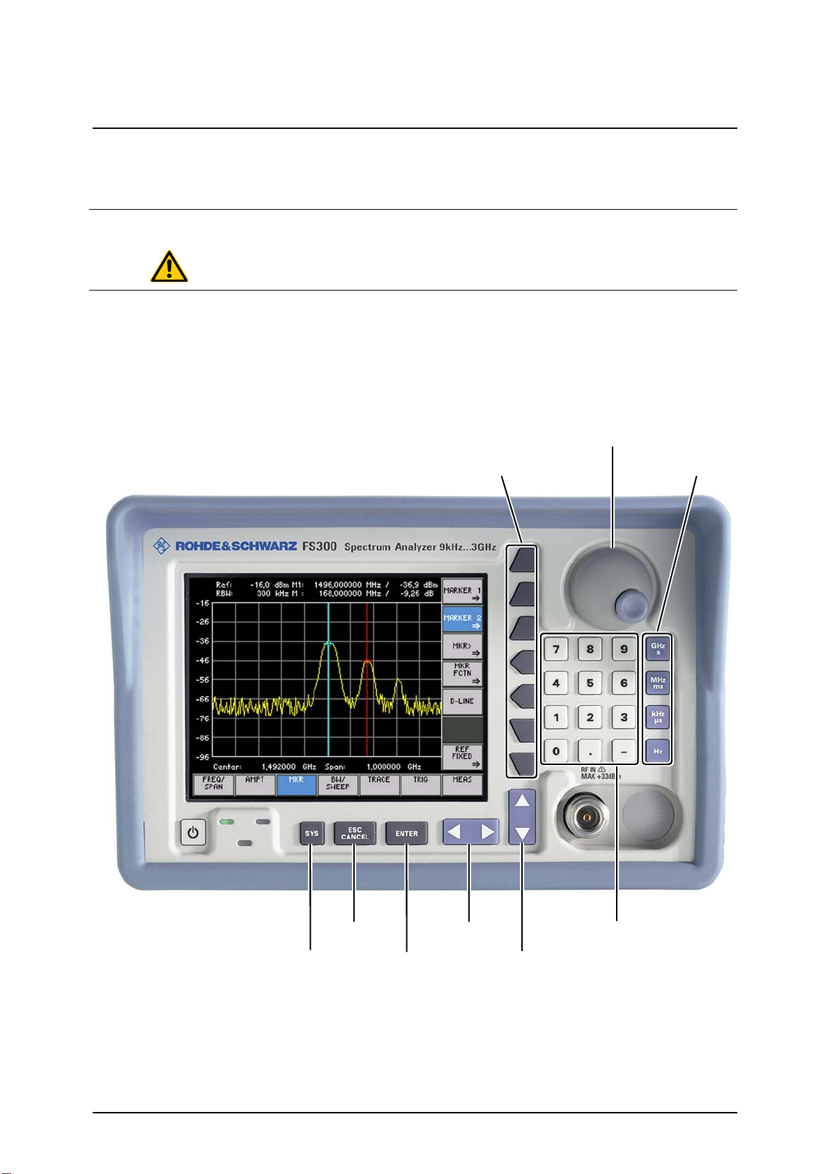
Connecting an External Keyboard R&S FS300
[
]
[
[
]
3.7 Connecting an External Keyboard
ATTENTION
Use
Key assignment for
operating the
R&S FS300
Only connect the keyboard when the R&S FS300 is off or in the STANDBY
mode, otherwise malfunctions may occur at a later date.
You can connect an external PC keyboard via the 6-pin PS/2 KEYBOARD
connector [21] on the R&S FS300’s rear panel. The keyboard makes it easier
to enter file names. The keyboard allows data entry as well as operation of
the R&S FS300.
The keyboard is detected automatically when it is connected.
[ F10 ] ⇐ | ⇒ [ F11 ]
F1 ] ... [ F7
[ A ] ... [ D ]
E-1007.9900.15 3-46 Operating manual, 02/2006
[ F9 ]
[ Esc ]
Enter
[ ], [ ]
[ ], [ ]
0 ] ... [ 9 ], [ . ], [ - ]
Page 47

R&S FS300 Connecting a USB Stick
3.8 Connecting a USB Stick
ATTENTION
Use
To ensure that the USB stick is detected by the R&S FS300, the stick must
be formatted in the FAT32 file system.
You can connect an external USB stick to the USB device interface [16] at the
rear of the R&S FS300. The USB stick is an extension of the internal memory. You can use it to save or load instrument settings, to print into a file on
the USB stick or to transfer trace data to a PC.
Operating manual, 02/2006 3-47 E-1007.9900.15
Page 48

Level and Frequency Measurements R&S FS300
4 Getting Started
This chapter
Further
information
Chapter 4 uses a number of simple measurements to illustrate how to operate the R&S FS300.
For the following example, the initial setting for instrument is the default setting (factory). This is set by pressing the PRESET key in the menu ( 6-153).
The full default setup is described in chapter 6.
Chapter 5 contains an in-depth explanation of the basic operating steps, for
example selecting menus and setting parameters. The layout of the screen
and the information displayed on the screen are also described.
Chapter 6 describes all the R&S FS300‘s menus and the associated functions in detail.
4.1 Level and Frequency Measurements
4.1.1 Measurement Task
ATTENTION
Measurement
problem
The input stage of the R&S FS300 can be destroyed by overloads or DC
components. If there is a possibility that the limits specified in the data sheet
may be violated, the input must be protected with an attenuator and/or a DC
block.
Determining the level and frequency of a signal is one of the most common
measurements a spectrum analyzer is used to make. Often, when making
these measurements on an unknown signal, the PRESET settings (factory)
are chosen as a suitable initial setup ( 6-153).
Solution
The center frequency (CENTER), the SPAN and the MARKER functions play
a key role in level and frequency measurements.
E-1007.9900.15 4-48 Operating manual, 02/2006
Page 49

R&S FS300 Level and Frequency Measurements
4.1.2 Measurement Procedure
Introduction
Measurement
steps
In this example, a signal with a frequency of 200 MHz and a level of -30 dBm
is applied to the RF input [8]. The center frequency and the span are set
manually.
Perform the following steps:
1. Reset the R&S FS300.
• Press the
• Select
• Press the
key.
in the bottom menu bar using the
function key.
cursor keys.
2. Apply the signal.
3. Set the center frequency (CENTER) to 200 MHz.
• Select
in the bottom menu bar using the
• Press the
• Enter
using the numerical keys. Terminate the entry
by pressing the unit key
function key.
.
cursor keys.
4. Reduce the SPAN to 1 MHz.
• Stay in the
menu.
• Press the
• Enter
the unit key
function key.
from the numerical keys. Terminate the entry by pressing
.
5. Measure the level and frequency with the marker.
• Select
• Press the
• Press the
in the bottom menu bar using the
function key.
function key in the submenu that appears. The
cursor keys.
marker jumps to the signal peak. Turn the rotary knob
change the position of the marker.
6. Frequency measurements with the built-in frequency counter.
• Press the
function key in the submenu. You can
change the resolution of the frequency counter in the same submenu
with the
function key.
to
Operating manual, 02/2006 4-49 E-1007.9900.15
Page 50

Making Entries from the Keypad R&S FS300
5 Manual Operating Concept
This chapter
Further
information
Chapter 5 contains an overview of the R&S FS300’s basic manual operating
concept. This includes a description of the keypad, the screen layout, menu
operation and how to set parameters. There is an overview of the menus and
functions at the end of this chapter.
Chapter 4 contains a brief introduction that takes you step-by-step through
some simple measurements.
Chapter 6 contains an in-depth description of the menu functions.
Chapter 7 contains note for remote control the R&S FS300 via a USB interface.
5.1 Making Entries from the Keypad
Introduction
The R&S FS300 is operated using menus in conjunction with a keypad and a
rotary knob. The keypad comprises the following sections:
Numerical keys [11]
Unit keys [9]
Cursor keys [6, 7]
Function keys [12]
Action keys [4, 5]
SYS key [3]
5.1.1 Numerical Keys
Function
...
The numerical keys are used to enter numerical parameters.
− Inserts one of the digits “0” to “9” at the cursor position.
− Inserts a decimal point “.” at the cursor position.
− Inserts a minus sign “-” at the cursor position.
5.1.2 Unit Keys
Function
The unit keys are used to assign the appropriate unit to the number that has
been entered, simultaneously terminating the entry.
− Assigns GHz when a frequency setting is being made
− Assigns s when a time setting is being made
− Assigns MHz when a frequency setting is being made
− Assigns ms when a time setting is being made
− Assigns kHz when a frequency setting is being made
− Assigns µs when a time setting is being made
− Assigns Hz when a frequency setting is being made
NOTE
E-1007.9900.15 5-50 Operating manual, 02/2006
In the case of all other entries, the unit keys assume the same function as the
Enter key. ( 5-52).
Page 51

R&S FS300 Making Entries from the Keypad
5.1.3 Rotary Knob
Function
As well as the numerical keys and the cursor keys, the rotary knob is also
used to set parameters.
The rotary knob has several functions:
− Incrementing (turn clockwise) or decrementing (turn counter-
clockwise) numerical instrument parameters using a specified step size.
− Positioning markers, limits, etc on the screen.
5.1.4 Cursor Keys
Function
As well as the numerical keys and the rotary knob, the cursor keys are also
used for entering parameters and to navigate through the menus.
The cursor keys have the following functions:
− Navigating through menus and selection fields
− The 3 or
the numerical editing line.
− The 6 or
entries.
5.1.5 Function Keys
cursor keys move the cursor to the position you want within
4
cursor keys increment or decrement numerical parameter
5
Function
In the function area, various instrument functions are displayed depending on
which menu has been selected.
The displayed instrument functions are assigned to the seven function keys
down the right side of the screen. This means that each function key can
have a variety of functions ( 5-55).
When a function key is pressed, various responses can be elicited:
− Immediate activation of a function or toggling between settings
− Entry of a value or selection of a setting/function
− Confirmation of a new setting and opening of a new menu item
− Branching to a submenu
Operating manual, 02/2006 5-51 E-1007.9900.15
Page 52

Making Entries from the Keypad R&S FS300
5.1.6 Action Keys
Function
The action keys are for terminating menu-guided settings.
− This key is for closing the entry field or selection field after data has
− This key is for closing the entry field or selection field, but the data that
5.1.7 SYS Key
Function
− When you press the SYS key [3], the measuring menu is blanked out
− By repeatedly pressing the SYS key [3], you can quit the SYS menu and
been entered. The new value is set on the R&S FS300.
NOTE: Pressing a unit key will also terminate the entry of setting data.
has been entered is not saved - in other words the old value is retained.
and replaced by the SYS menu. Other functions are assigned to the
function keys [12] and the measurement diagram is replaced by the system parameters ( 6-151).
accept the new settings.
E-1007.9900.15 5-52 Operating manual, 02/2006
Page 53

R&S FS300 Screen Display
5.2 Screen Display
Introduction
Screen layout
The screen [13] provides on-going information about events and the parameters associated with the selected measurement functions.
The display mode for the measurement results, the lettering of the function
keys and the type of menu all depend on the current settings.
The screen is divided into three areas:
I Diagram area
II Menu area
III Function area
I
III
II
Operating manual, 02/2006 5-53 E-1007.9900.15
Page 54

Screen Display R&S FS300
5.2.1 Diagram Area
Displays in the
diagram area
The diagram area contains:
Measurement diagrams and the associated scales (h) and traces (e)
Measured value displays, e.
g. display line (d) and markers (c)
Parameter field (b) and status displays (a)
Selection fields and entry fields that come up on the screen (g)
Error messages that come up on the screen (f)
a
b
c
h
d
e
g
f
Measurement
diagram
Parameter field
and
status display
A 10 x 8 grid is superimposed on the diagram area to make it easier to analyze traces.
The following are displayed in the parameter field:
Ref: - upper diagram limit (reference level)
RBW: - current resolution bandwidth
M1: - marker 1 plus marker position and level
M2: - marker 2 plus marker position and level
The status display provides the following information:
Offs - level offset is on
MAX - current trace display mode, e.
5.2.2 Menu Area
Menu display
Menus for setting the measurement parameters and the measurement functions are displayed in the menu area. The selected menu is highlighted, e.
FREQ/SPAN menu:
g. max hold
g.
E-1007.9900.15 5-54 Operating manual, 02/2006
Page 55

R&S FS300 Screen Display
5.2.3 Function Area
Displaying the
current assignment
for the function keys
When a menu is selected, the associated instrument functions are displayed
in the function area.
The displayed instrument functions are assigned to the seven function keys
down the right-hand side of the screen. If a key in the function area does not
have any lettering, the key has not been assigned a function in the menu in
question. If a key has lettering, but not in full brightness, the key has temporarily (current setting) not been assigned a function.
Activated function key
De-activated function key
No function assigned
Operating manual, 02/2006 5-55 E-1007.9900.15
Page 56

Calling and Changing Menus R&S FS300
5.3 Calling and Changing Menus
Introduction
Calling or
changing menus
Operating the R&S FS300 is menu-guided. All the menus used to set the
measurement parameters and measurement functions are displayed in the
menu area. The instrument functions associated with any menu you select
are displayed in the function area.
Pressing a function key has one of the following effects:
Direct execution of an instrument function
Opening of entry or selection windows
Opening of submenus
The 3 or 4 cursor keys [6] are used for menu navigation.
1. Select a menu, e.
g. , with the
3
or
[6] cursor keys.
4
The menu name is highlighted and the appropriate function is assigned
to the function keys [12].
NOTE
A double arrow ⇒ pointing to a function key, e. g. , tells you that
pressing this key will call a submenu.
E-1007.9900.15 5-56 Operating manual, 02/2006
Page 57

R&S FS300 Calling and Changing Menus
Calling/quitting
submenus
2. Press the
function key in the
menu.
The MARKER 1 submenu opens and the new functions are assigned to
the function keys [12].
3. Press the
function key in the submenu.
The submenu is closed and the previous functions remain assigned to
the function keys [12].
Operating manual, 02/2006 5-57 E-1007.9900.15
Page 58

Setting Parameters R&S FS300
5.4 Setting Parameters
There is a choice
of methods
Parameters can be set in a number of ways:
Direct selection of an instrument function (function key)
Selecting settings from selection fields
Entering numerical parameters in entry fields
The numerical keys [11], the unit keys [9], the rotary knob [10], the cursor
keys [6, 7] and the action keys [4, 5] can all be used to select and enter instrument parameters.
5.4.1 Direct Selection of Instrument Functions
Introduction
e.
g. :
Displaying marker 1
( 6-99)
When you select a menu, various instrument functions are displayed in the
function area. Some instrument functions can be set directly by pressing a
function key.
The function key you select is highlighted.
1. Press the
function key in the submenu.
Marker 1 is turned on and placed on the trace maximum. The M1 marker
values are displayed in the parameter field.
2. Press the
function key in the submenu.
Marker 1 disappears from the diagram area and the M1 marker values
are blanked out.
E-1007.9900.15 5-58 Operating manual, 02/2006
Page 59

R&S FS300 Setting Parameters
5.4.2 Selecting Settings
Introduction
e.
g. :
Setting the level
display range
( 6-90)
When you select a menu, a number of instrument functions are displayed in
the function area. If certain function keys are then pressed, a selection field is
displayed in the diagram area. You can then choose and activate any of the
settings offered for selection.
The function key you select is highlighted.
1. Press the
A selection field containing the available settings is displayed. The default setting is “80 dB”.
function key in the menu.
NOTE
2. Select a level display range with rotary knob
3. Press the ENTER key [5] to close the selection field.
The new setting is saved.
If you want to keep the old setting, close the entry field with the
ESC/CANCEL key [4].
If there are more than five options, a scroll bar is displayed on the right next
to the selection field. At any one time, only five options are displayed on the
screen.
[10].
Operating manual, 02/2006 5-59 E-1007.9900.15
Page 60

Setting Parameters R&S FS300
5.4.3 Entering Numerical Parameters
Introduction
When you select a menu, a number of instrument functions will be displayed
in the function area. If you press certain function keys, an entry field will be
displayed in the diagram area.
The function key you select is highlighted.
There are two ways of entering numerical parameters:
Entry of a number with the numerical keys
Entry of a number with the cursor keys and rotary knob
The entry with the cursor keys and rotary knob is useful if you only have a
rough idea of what the measurement parameters should be. As the screen is
continuously updated as the value is varied, a search is possible.
5.4.3.1 Entry with the Numerical Keys
e. g. :
Setting the
center frequency
( 6-77)
1. Press the
An entry field containing the current setting is displayed.
function key in the menu.
Entering
a new value
2. Overwrite the old value, e.
g. 1.5 GHz, with the numerical keys [11].
NOTE: If a numerical key is pressed after the entry field is brought up on
the screen, the old value will be erased. However, a complete new value
must now be entered using the numerical keys.
E-1007.9900.15 5-60 Operating manual, 02/2006
Page 61

R&S FS300 Setting Parameters
Terminating
entries
3a. Press a unit key [9], e.
g. GHz, to terminate the entry.
The R&S FS300 sets the value that has been set numerically using the
new unit. The entry window is closed.
3b. Press the ENTER key [5] to terminate the entry.
Invalid
parameter entry
NOTE
The R&S FS300 sets the value that has been set numerically, but with
the old unit. The entry window is closed.
NOTE: If a parameter is unitless or always has the same unit, you can
terminate the entry with the ENTER key or one of the unit keys.
3c. Press the ESC/CANCEL key [4] to abort the entry.
The old value is retained. The entry window is closed.
If an invalid parameter is entered, the new value is rejected by the R&S
FS300 and an error message is issued:
• Acknowledge the error message with the ENTER key [5] and repeat the
entry with the correct value.
When numbers are displayed, only the digit sequences 1 to 999 appear before the decimal point. In other words, if the digit sequence <5000> and the
unit <kHz> are entered, <5 MHz> appears in the display. Trailing zeros will
be eliminated in the display area.
Operating manual, 02/2006 5-61 E-1007.9900.15
Page 62

Setting Parameters R&S FS300
5.4.3.2 Entry using the Cursor Keys and the Rotary Knob
e. g. :
Setting the span
( 6-77)
Entering
a new value,
g. 1.6
e.
1. Press the
An entry field containing the current setting is displayed.
2. Using the cursor keys
place in the entry field.
1 ×
3a. Press the
Pressing the
the 6 cursor key once decrements the value by one.
6
function key in the menu.
and 4 [6], position the cursor on a decimal
3
or
cursor key [7] until you obtain the value you want.
5
cursor key once increments the value by one; pressing
5
6 ×
3b. Turn the rotary knob [10] until you obtain the value you want.
Turning clockwise increases the value; turning counter-clockwise reduces the value.
6 ×
NOTE: In both cases, there are carries associated with incrementation or
decrementation. In other words, if a 9 digit is incremented or a 0 digit
decremented, a carry is added to or subtracted from next highest digit.
When you enter the center frequency, you can specify the step width of the
NOTE
E-1007.9900.15 5-62 Operating manual, 02/2006
rotary knob. ( 6-79). In this case, the value is incremented or decremented
in accordance with the specified step width, with the cursor always moving to
the highest value, irrespective of its earlier position.
Page 63

R&S FS300 Setting Parameters
Terminating
entries
Invalid
parameter entry
4a. Press a unit key [9], e.
g. MHz, to terminate the entry.
The R&S FS300 sets the value that has been entered using the new
unit. The entry window is closed.
4b. Press the ENTER key [5] to terminate the entry.
The R&S FS300 sets the value that has been set numerically but with the
old unit. The entry window is closed.
NOTE: If a parameter is unitless or always has the same unit, you can
terminate the entry with the ENTER key or one of the unit keys.
4c. Press the ESC/CANCEL key [4] to abort the entry.
The old value is retained. The entry window is closed.
If the limit value is reached, the numeric value in the entry window remains
the same and is neither increased nor decreased. No error message is issued.
NOTE
When numbers are displayed, only the digit sequences 1 to 999 appear before the decimal point. In other words, if the digit sequence <5000> and the
unit <kHz> are entered, <5 MHz> appears in the display. Trailing zeros will
be eliminated in the display area.
Operating manual, 02/2006 5-63 E-1007.9900.15
Page 64

Overview of all Menus and Functions R&S FS300
5.5 Overview of all Menus and Functions
5.5.1 Spectrum Analyzer
5.5.1.1 FREQ/SPAN Menu
Function key
assignment
Entering the center frequency ( 6-77)
Entering the span ( 6-77)
Entering the start frequency ( 6-78)
Entering the stop frequency ( 6-78)
Open submenu:
Entering the step width of the center frequency
Open submenu:
Display modes for the frequency axis
Quitting the submenu
Setting the step size manually ( 6-80)
Setting the step size automatically ( 6-80)
Setting the step size to the center frequency ( 6-80)
Setting the step size to the marker frequency ( 6-80)
Open submenu:
Signal tracking
E-1007.9900.15 5-64 Operating manual, 02/2006
Quitting the submenu
Displaying the whole frequency range ( 6-82)
Switching over to the ZERO SPAN ( 6-83)
Restoring the previous setting ( 6-83)
Reducing the span ( 6-84)
Increasing the span ( 6-84)
Expanding the diagram area to fill the whole screen ( 6-84)
Quitting the submenu
Activating signal tracking ( 6-86)
De-activating signal tracking ( 6-86)
Page 65

R&S FS300 Overview of all Menus and Functions
5.5.1.2 AMPT Menu
Function key
assignment
Entering the reference level ( 6-88)
Entering a level offset ( 6-89)
Selecting the level display range ( 6-90)
Selecting a unit for the level display ( 6-91)
Setting the RF input attenuation manually ( 6-93)
Setting the RF input attenuation automatically ( 6-94)
Selecting the setting High Sensitivity ( 6-96)
Operating manual, 02/2006 5-65 E-1007.9900.15
Page 66

Overview of all Menus and Functions R&S FS300
5.5.1.3 MKR Menu
Function key
assignment
Open submenu:
Activate marker 1
Quitting the submenu
Place marker 1 on the trace maximum ( 6-99)
Place marker 1 on the next trace maximum to the left ( 6-99)
Place marker 1 on the next trace maximum to the right ( 6-99)
Measure the signal frequency: Start measurement ( 6-101)
Measure signal frequency: Set resolution ( 6-101)
De-activate marker 1 ( 6-99)
Open submenu:
Activate marker 2
Quitting the submenu
Place marker 2 on the trace maximum ( 6-103)
Place marker 2 on the next trace maximum to the left ( 6-103)
Place marker 2 on the next trace maximum to the right ( 6-103)
Set marker 2 as a normal marker (NORM) ( 6-104)
Set marker 2 as a delta marker (DELTA) ( 6-104)
De-activate marker 2 ( 6-103)
Open submenu:
Accepting marker values as settings
Quitting the submenu
Set the center frequency to the marker frequency ( 6-106)
Set the marker level as a reference level ( 6-106)
Set the step size for entering the center frequency to the marker
frequency ( 6-108)
E-1007.9900.15 5-66 Operating manual, 02/2006
Page 67

R&S FS300 Overview of all Menus and Functions
Open submenu:
Marker measurement functions
Quitting the submenu
Measuring noise power density ( 6-110)
Measuring signal bandwidth ( 6-111)
Bring display line up on screen ( 6-113)
Open submenu:
Search criterion of functions NEXT PEAK LEFT/RIGHT
Quitting the submenu
Entering the peak excursion ( 6-115)
Open submenu:
Reference points for measuring level differences
Quitting the submenu
Activating the entry of arbitrary reference points ( 6-118)
Using M1 marker values as a reference point ( 6-118)
Entering the reference-point level ( 6-118)
Entering the reference-point frequency ( 6-118)
Entering the reference-point time ( 6-118)
Operating manual, 02/2006 5-67 E-1007.9900.15
Page 68

Overview of all Menus and Functions R&S FS300
5.5.1.4 BW/SWEEP Menu
Function key
assignment
Setting the resolution bandwidth manually ( 6-122)
Activating automatic resolution bandwidth setting ( 6-122)
Setting the video bandwidth manually ( 6-123)
Activating automatic video bandwidth setting ( 6-123)
Open submenu:
Setting the RBW/VBW coupling ratio
Quitting the submenu
Setting the coupling ratio RBW/VBW manually
( 6-125)
Activating the default setting for the coupling ratio RBW/VBW
( 6-125)
Switching over the coupling RBW/SPAN to low noise
( 6-126)
Open submenu:
Setting the sweep time
Quitting the submenu
Starting a continuous frequency sweep ( 6-128)
Performing an n-times sweep ( 6-128)
Setting the number of sweeps ( 6-128)
Repeating n-times sweeps ( 6-129)
Setting the sweep time manually ( 6-129)
Activating automatic sweep-time setting ( 6-129)
E-1007.9900.15 5-68 Operating manual, 02/2006
Page 69

R&S FS300 Overview of all Menus and Functions
5.5.1.5 TRACE Menu
Function key
assignment
Open submenu:
Selecting the active trace
Quitting the submenu
Turning on and activating Trace 1 ( 6-132)
Turning on and activating Trace 2 ( 6-132)
Trace display mode: Overwrite mode ( 6-134)
Trace display mode: Min./Max. hold ( 6-134)
Trace display mode: Averaging ( 6-134)
Freezing the trace ( 6-134)
Blanking out the trace ( 6-134)
Open submenu:
Trace difference
Quitting the submenu
Turning on the trace-difference mode ( 6-138)
Repositioning Trace 1 (result) ( 6-138)
Turning off the trace-difference mode ( 6-138)
Operating manual, 02/2006 5-69 E-1007.9900.15
Page 70

Overview of all Menus and Functions R&S FS300
5.5.1.6 TRIG Menu
Function key
assignment
Free-running measurements ( 6-141)
Open submenu:
Triggering by an external TTL signal
Quitting the submenu
Triggering on positive-going edge ( 6-144)
Triggering on negative-going edge ( 6-144)
Triggering by the display level ( 6-141)
Triggering by the AC-line frequency ( 6-141)
Entering a trigger offset ( 6-144)
E-1007.9900.15 5-70 Operating manual, 02/2006
Page 71

R&S FS300 Overview of all Menus and Functions
5.5.1.7 MEAS Menu
Function key
assignment
Open submenu:
Measure the power in the time domain (ZERO SPAN)
Quitting the submenu
Output the peak value within the section ( 6-147)
Output the mean value within the section ( 6-147)
Insert a vertical line
to limit the lower (left) part of a section ( 6-147)
Insert a vertical line
to limit the upper (right) part of a section ( 6-147)
Switch off the power measurement ( 6-147)
Measure the third-order intercept point ( 6-150)
Operating manual, 02/2006 5-71 E-1007.9900.15
Page 72

Overview of all Menus and Functions R&S FS300
5.5.2 SYSTEM Functions
5.5.2.1 PRESET Menu
Function key
assignment
Calls an instrument default setting ( 6-154)
Selects an instrument default setting ( 6-154)
5.5.2.2 STATUS Menu
Function key
assignment
Displaying the current instrument setting ( 6-155)
5.5.2.3 FILE Menu
Function key
assignment
Saves a user-defined setting/waveform ( 6-157, 6-159)
Loads a user-defined setting/waveform ( 6-157, 6-159)
Prints out a screenshot ( 6-157)
5.5.2.4 CONFIG Menu
Function key
assignment
Sets the date and time ( 6-166)
Selects an internal or external reference source ( 6-168)
Configures the instrument interfaces ( 6-169)
Sets the screen saver mode ( 6-171)
Selects an internal or external monitor ( 6-173)
5.5.2.5 SERVICE Menu
Function key
assignment
E-1007.9900.15 5-72 Operating manual, 02/2006
Performs a selftest ( 6-174)
Page 73

R&S FS300 Overview of all Menus and Functions
5.5.2.6 INFO Menu
Function key
assignment
Displays module data ( 6-176)
Displays instrument statistics ( 6-176)
Displays system messages ( 6-177)
Operating manual, 02/2006 5-73 E-1007.9900.15
Page 74

R&S FS300 Factory Settings R&S FS300
6 Using the R&S FS300
This chapter
Further
information
All the spectrum analyzer functions and their uses are fully described in chapter 6. The order in which the menus are described follows that of the procedures for configuring and starting measurements:
R&S FS300 default settings
Setting measurement parameters
Selecting and configuring measurement functions
The operating concept is explained in chapter 5, which also contains an overview of the menus and functions.
The index at the end of this manual will also help you find the information you
want.
6.1 R&S FS300 Factory Settings
Switching on for the
first time
Frequency axis
When you switch on the R&S FS300 ( 3-44), the settings you were using
when the instrument was last switched off are restored.
When you switch on for the first time, the factory default settings are activated:
Parameter Setting
Center frequency (CENTER) 1.5 GHz
Frequency span (SPAN) 3 GHz
Level axis
RF input
Bandwidth
Frequency sweep
Trace
Trigger
Markers
NOTE
Step size for center frequency 150 MHz
Reference level (REF LEVEL) -20 dBm
Level offset (REF LEVEL OFFSET) 0 dB
Level range (RANGE) 80 dB
Level unit (UNIT) dBm
Input attenuation (RF ATTEN) AUTO (NORMAL)
Sweep time (SWEEP TIME) AUTO
Resolution bandwidth (RES BW) AUTO (1 MHz)
Video bandwidth (VIDEO BW) AUTO (1 MHz)
Sweep CONT SWEEP
Trace CLEAR/WRITE
Trigger FREE RUN
Marker 1 and marker 2 OFF
The factory default setting is stored in non-volatile memory in the R&S FS300
and can be reloaded at any time ( 6-153).
E-1007.9900.15 6-74 Operating manual, 02/2006
Page 75

R&S FS300 Spectrum Analyzer
6.2 Spectrum Analyzer
Introduction
User interface
Menus for configuring and starting
measurements
The R&S FS300 measures signal spectra over the selected frequency range
using the selected resolution bandwidth and sweep. The time characteristic
of the amplitude at the set frequency is displayed in zero span.
When the R&S FS300 is switched on and the selftest passed, the spectrum
analyzer’s user interface is activated. The following is displayed on the
screen [13]:
The menus used to set the spectrum analyzer are displayed in the menu
area. The order of the menus mirrors that of the procedure for configuring
and starting measurements:
Selecting the frequency span ( 6-76)
(setting the x axis in the diagram area)
Setting the level axis and the RF input ( 6-87)
(setting the y axis in the diagram area)
Signal analysis with marker functions ( 6-96)
Setting the bandwidths and the sweep time ( 6-121)
Displaying the trace ( 6-130)
Triggering the measurement ( 6-140)
Measurement functions ( 6-145)
Operating manual, 02/2006 6-75 E-1007.9900.15
Page 76

Spectrum Analyzer R&S FS300
6.2.1 Selecting the Frequency Span (FREQ/SPAN Menu)
What the settings
are for
Selecting the
FREQ/SPAN
menu
Function key
assignment
,
Use the FREQ/SPAN menu to specify the frequency range.
• Select the
menu using the
3
or
cursor key [6].
4
The menu name is highlighted and the appropriate functions are assigned to the function keys.
1st variant: Setting the frequency range ( 6-77)
Enter the center frequency (CENTER) and the SPAN
,
2nd variant: Setting the frequency range ( 6-78)
Enter the START and STOP frequencies
Open submenu:
Entering the step width of the center frequency ( 6-79)
Open submenu:
Frequency axis display modes ( 6-81)
Open submenu:
Signal tracking ( 6-85)
E-1007.9900.15 6-76 Operating manual, 02/2006
Page 77

R&S FS300 Spectrum Analyzer
6.2.1.1 Entering the Center Frequency and the Span
Use
Entering the
center frequency
If you know the frequency of the signal you want to measure, you can set the
x axis of the diagram area accordingly. Enter the signal frequency as the
center frequency (CENTER) and specify a SPAN.
SPAN
CENTER
1. Press the
An entry field containing the current setting is displayed:
2. Enter the new value ( 5-60).
The entry range for the center frequency is:
function key in the menu.
Setting the span
NOTE
500 Hz ≤ Center ≤ 2.9999995 GHz
3. Press the
An entry field containing the current setting is displayed:
4. Enter the new value ( 5-60).
The span entry range is:
1 kHz ≤ Span ≤ 3 GHz
The new setting is saved and displayed in the diagram area. The grid
lines associated with the frequency axis represent 1/10 of the current
span.
The effect of pressing the or function key is to switch the
frequency axis lettering in the diagram area to the display showing the current
center frequency and the span.
function key in the menu.
Operating manual, 02/2006 6-77 E-1007.9900.15
Page 78

Spectrum Analyzer R&S FS300
6.2.1.2 Entering the Start Frequency and the Stop Frequency
Use
Entering a start
frequency
If you want to analyze a specific frequency range, you can enter a start frequency and a stop frequency. The frequency range is shown along the x axis
of the diagram area.
START STOP
1. Press the
An entry field containing the current setting is displayed:
2. Enter the new value ( 5-60).
The entry range for the start frequency is:
function key in the . menu.
Entering a stop
frequency
NOTE
0 ≤ Start ≤ 2.999999 GHz
3. Press the
An entry field containing the current setting is displayed:
4. Enter the new value ( 5-60).
The entry range for the stop frequency is:
1 kHz ≤ Stop ≤ 3 GHz
The new setting is saved and displayed in the diagram area. The grid
lines associated with the frequency axis represent 1/10 of the current
span.
The effect of pressing the or the function key is to switch the
lettering of the frequency axis in the diagram area to the display showing the
current start and stop frequencies.
function key in the menu.
E-1007.9900.15 6-78 Operating manual, 02/2006
Page 79

R&S FS300 Spectrum Analyzer
6.2.1.3 Entering the Step Width of the Center Frequency
What the settings
are for
Selecting the
CF STEP SIZE
submenu
Function key
assignment
Using the CF STEP SIZE submenu, you can set any step size of the rotary
knob you want or have the R&S FS300 set a step size that is a function of the
measurement parameters.
• Press the
The submenu opens and the appropriate functions are assigned to the
function keys.
Quitting the submenu
function key in the menu.
NOTE
Setting the step size manually ( 6-80)
Setting the step size automatically ( 6-80)
Setting the step size to the center frequency ( 6-80)
Setting the step size to the marker frequency ( 6-80)
The and function keys are selection keys. In other words,
only one setting can be activated at any one time. The function key in question is highlighted.
The AUTO function is the default setting.
The
function key is available only when marker 1 is turned on.
Operating manual, 02/2006 6-79 E-1007.9900.15
Page 80

Spectrum Analyzer R&S FS300
6.2.1.3.1 Setting the Step Size
Setting the step size
manually
Setting the
step size
automatically
Setting the
step size to the
center frequency
If you want to examine the frequency spectrum at certain intervals, you can
enter the value of your choice for the step size of the rotary knob.
1. Press the
function key in the
submenu.
An entry field containing the current setting is displayed:
2. Enter the new value ( 5-60).
The entry range for the step size is:
1 Hz ≤ Step Size ≤ 2.999999 GHz
If you want to change the center frequency using steps that are small compared with the span, select the automatic setting mode.
• Press the
function key in the
submenu.
The step size is set to a tenth of the current span.
If you make the step size equal to the center frequency (or an integer multiple
of the center frequency), it is easy to find harmonics which are multiples of
the center frequency.
• Press the
function key in the submenu.
The step size is made equal to the current center frequency.
Setting the
step size to the
marker frequency
If you make the step size equal the marker frequency, you can search
through the frequency spectrum and quickly jump back to the frequency at
which you started.
• Press the
function key in the submenu.
The step size is made equal to the current marker frequency ( 6-96).
E-1007.9900.15 6-80 Operating manual, 02/2006
Page 81

R&S FS300 Spectrum Analyzer
6.2.1.4 Frequency-Axis Display Modes
What the settings
are for
Selecting the
SPAN SETTINGS
submenu
The frequency axis (x axis) can be displayed in a number of ways. Using the
SPAN SETTINGS submenu, you can display the whole frequency range,
zoom in on subranges of the frequency axis or project the diagram area onto
the whole of the screen, if and when you require.
If you switchover to the time domain (ZERO SPAN), you can display the
amplitude of the carrier signal as functions of time.
• Press the
function key in the menu.
The submenu opens and the appropriate functions are assigned to the
function keys [12].
Function key
assignment
Quitting the submenu
Displaying the whole frequency range ( 6-82)
Switching over to the ZERO SPAN ( 6-83)
Restoring the previous setting ( 6-83)
Zoom function: Reducing the span ( 6-84)
Zoom function: Increasing the span ( 6-84)
Zoom function: Filling the whole screen with the diagram area
( 6-84)
Operating manual, 02/2006 6-81 E-1007.9900.15
Page 82

Spectrum Analyzer R&S FS300
6.2.1.4.1 Displaying the Whole Frequency Range
Use
Displaying the whole frequency range
Displaying the
last span
If you do not know the frequency of the signal to be investigated, you can
display the R&S FS300’s whole frequency range along the x axis of the diagram area. You can then systematically reduce the span to the appropriate
size ( 6-77).
The whole frequency range display can also be used to swap backwards and
forwards between an overview measurement (FULL SPAN) and a detailed
measurement (LAST SPAN, e.
1. Press the
function key in the
g. center frequency and span set manually).
menu.
The old setting is saved and the R&S FS300’s whole frequency range is
displayed in the diagram area.
FULL SPAN
2. Press the
The last span setting is displayed in the diagram area, e.
function key in the
menu.
g. 1 GHz:
NOTE
The last span is restored if and only if the span is > 0, in other words, the time
domain (ZERO SPAN) will not be selected automatically.
E-1007.9900.15 6-82 Operating manual, 02/2006
Page 83

R&S FS300 Spectrum Analyzer
6.2.1.4.2 Switching over to the ZERO SPAN
Use
Specifying
the signal
component
Switching over to the ZERO SPAN
The amplitude of a particular signal component in the frequency spectrum
can be displayed as a function of time. To activate this mode, enter the frequency of the signal component as the center frequency. You can then define
the x axis to be the time axis.
1. Press the
function key in the menu.
An entry field containing the current setting is displayed:
2. Enter the frequency of the signal component you want to display in the
time domain ( 6-77).
3. Press the
function key in the submenu.
The x axis becomes the time axis and the signal amplitude at the current
center frequency is displayed as a function of time (current sweep time).
The grid line spacing represents 1/10 of the current sweep time ( 6-
126).
Switching over to
the frequency
domain
SWEEP TIME
4. Press the
function key in the
The last span is displayed in the diagram area.
submenu.
Operating manual, 02/2006 6-83 E-1007.9900.15
Page 84

Spectrum Analyzer R&S FS300
6.2.1.4.3 ZOOM Functions
Use
Reducing
the span
Increasing
the span
If you want to increase or decrease the size of the screen window to analyze
traces, you can zoom onto sections of the span or fill the whole screen with
the current screen window.
• Press the
function key in the submenu.
The span is reduced by a factor of two. The center frequency remains
the same.
• Press the
function key in the submenu.
The span is increased by a factor of two. The center frequency remains
the same. The center frequency will be adapted if the new display frequency range exceeds the maximum permissible start or stop frequency.
Whole screen
1. Press the
function key in the submenu.
The menu area, the function area and the parameter field are blanked
out on the screen [13]. The diagram area then fills the whole screen. The
scale lettering and all key parameters are displayed within the diagram
area.
2. Press any key to return to the normal display mode.
E-1007.9900.15 6-84 Operating manual, 02/2006
Page 85

R&S FS300 Spectrum Analyzer
6.2.1.5 Signal Tracking
What the settings
are for
Selecting the
SIGNAL TRACK
submenu
When signal tracking is selected, the center frequency of the R&S FS300 is
continually set to the frequency of the signal with most power. This means
that a signal whose frequency is changing slowly in comparison with the
sweep time can be kept in the center of the screen. The capture range of the
function is ± span/5 referring to the center frequency. The spectrum analyzer’s center frequency is adjusted after each sweep.
• Press the
function key in the menu.
The submenu opens and the appropriate functions are assigned to the
function keys [12].
Function key
assignment
Quitting the submenu
Activating signal tracking ( 6-86)
De-activating signal tracking ( 6-86)
Operating manual, 02/2006 6-85 E-1007.9900.15
Page 86

Spectrum Analyzer R&S FS300
6.2.1.5.1 Activating Signal Tracking
Use
Activating signal tracking
De-activating
signal tracking
If the frequency of the signal being analyzed is continually varying, you can
use this function to obtain a display that appears to be stationary. The power
of signals of this kind can then be measured over long periods.
• Press the
function key in the submenu.
The center frequency is constantly adjusted so that the signal peak is always in the middle of the screen. The latest center frequency to be set is
displayed. The peak will continue to be tracked provided it remains within
the span referring to the center frequency.
• Press the
function key in the submenu.
The center frequency ceases to be tracked and remains at its last value.
E-1007.9900.15 6-86 Operating manual, 02/2006
Page 87

R&S FS300 Spectrum Analyzer
6.2.2 Setting the Level Axis and the RF Input (AMPT Menu)
What the settings
are for
Selecting the
AMPT menu
Function key
assignment
From the AMPT menu, you can define the y axis of the measurement diagram as the level axis. You can also specify the attenuation of the RF input.
• Select the
The menu name is highlighted and the appropriate functions are assigned to the function keys [12].
Entering the reference level ( 6-88)
menu with the
3
or
cursor key [6].
4
NOTE
Entering a level offset ( 6-89)
Selecting the level display range ( 6-90)
Selecting the level display unit ( 6-91)
Setting the RF input attenuation manually ( 6-93)
Setting the RF input attenuation automatically ( 6-94)
Selecting the setting High Sensitivity ( 6-96)
The and function keys are selection keys. In other words,
only one setting can be activated at any one time. The function key in question is highlighted.
The RF ATTEN AUTO function is the default setting.
Operating manual, 02/2006 6-87 E-1007.9900.15
Page 88

Spectrum Analyzer R&S FS300
6.2.2.1 Entering the Reference Level
Use
NOTE
Entering the reference level
The upper diagram limit is specified with the reference level.
REF LEVEL
The currently activated unit is used as the unit for reference level entries (
6-91). The default setting is “dBm”.
1. Press the
function key in the menu.
An entry field containing the current setting is displayed. The default setting is -20 dBm.
2. Enter a new value in 0.1 dB steps ( 5-60).
The entry range for the reference level is:
-110 [dBm] ≤ Reference
≤ +36 [dBm]
The new setting is saved and displayed in the diagram area. The reference level defines the upper limit of the diagram.
E-1007.9900.15 6-88 Operating manual, 02/2006
Page 89

R&S FS300 Spectrum Analyzer
6.2.2.2 Entering a Level Offset
Use
Entering a level offset
If you have connected external attenuators or amplifiers between the DUT
and the RF input, you can enter a level offset to adjust the level display. The
level offset is added to the reference level.
REF LEVEL + REF LEVEL OFFSET
1. Press the
function key in the menu.
An entry field containing the current setting is displayed. The default setting is 0 dB.
2. Enter a new value in 0.1 dB steps ( 5-60).
The entry range for the level offset is:
-100 [dB] ≤ Ref Lvl Offset ≤ +50 [dB]
The new setting is saved and displayed in the diagram area. The text
“Offs” is also displayed in the top left of the diagram.
The level offset is always entered in dB no matter what unit is used for
the reference level. If the units mV or mW are used, the offset is automatically converted so that the reference level is displayed correctly:
REF LEVEL
e.
g. = -20 dBm + 40 dB = 20 dBm
= REF LEVEL + REF LEVEL OFFSET
Display
Operating manual, 02/2006 6-89 E-1007.9900.15
Page 90

Spectrum Analyzer R&S FS300
6.2.2.3 Selecting the Level Display Range
Use
Use the level display range to define the “visible” level range and set the
measurement diagram scale.
RANGE
Levels can be displayed using either logarithmic or linear scales. The lettering
of the grid lines is automatically adapted.
8 dB
1 dB/div.
16 dB
2 dB/div.
40 dB
5 dB/div.
80 dB
10 dB/div.
Entering the level
display range
LINEAR
12.5 %/div., linear scale, 100 % corresponds to the reference level, 0 %
to 0 V or 0 W
1. Press the
function key in the menu.
A selection field containing the available settings is displayed. The default setting is 80 dB.
2. Select a level display range with rotary knob
[10].
3. Press the ENTER key [5] to close the selection field.
The new setting is saved and displayed in inverse video in the diagram
area. The level display range is referred to the reference level. This determines how the grid lines are lettered, for example, for REF LEVEL =
-20 dBm and RANGE = 80 dB, the first grid line is at -20 dBm and the
second at -30 dBm, and so on.
E-1007.9900.15 6-90 Operating manual, 02/2006
Page 91

R&S FS300 Spectrum Analyzer
NOTE
The level display range uses the currently activated unit ( 6-91).
6.2.2.4 Selecting the Level Display Unit
Use To make it easier to analyze results, you can display levels in dBm, dBmV,
dBµV, mV and mW.
Selecting the
unit for the
level display
How RANGE and
UNIT are related
1. Press the
A selection field containing the available settings is displayed. The default setting is dBm.
2. Select a unit for the level display with rotary knob
3. Press the ENTER key [5] to close the selection field.
The new setting is saved and displayed in the diagram area.
Log display/RANGE in dBx (The letter x is a wildcard character for the letters m, mV or µV.)
If a dB display has been selected for RANGE ( 6-90) and a dBx display for
UNIT, the vertical-scale unit is dB. The values indicated by the level markers
and the relevant level entries are in dBx.
function key in the menu.
[10].
Operating manual, 02/2006 6-91 E-1007.9900.15
Page 92
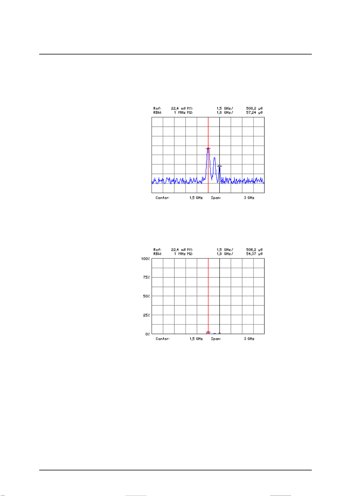
Spectrum Analyzer R&S FS300
Log display/RANGE in xV or xW (The letter x is a wildcard character for the
letters m, mV or µV.)
If a mV or mW has been selected for UNIT, only the reference level is displayed in the selected unit. There is no grid lettering. The values shown by
the level markers and the relevant level entries are in the selected unit.
Linear display/RANGE in xV or xW (The letter x is a wildcard character for
the letters m, mV or µV.)
If the linear scale is selected for RANGE, the scale lettering indicates percent,
e.
g. 0 %, 25 %, 50 %, 75 % and 100 %. The values indicated by the level
markers and the relevant level entries are in the selected unit.
E-1007.9900.15 6-92 Operating manual, 02/2006
Page 93

R&S FS300 Spectrum Analyzer
6.2.2.5 Setting the RF Input Attenuation Manually
Use
Setting the input
attenuation
manually
Invalid parameter
entry
In the default setting, the input attenuation is coupled to the reference level. In
most cases, this is the setting that will be used because it prevents the input
stages from being overdriven and so, consequently, any incorrect measurements.
In exceptional cases, it may be necessary to adjust the input attenuation
manually with input attenuations from 0 to 70 dB.
1. Press the
function key in the menu.
A selection field containing the available settings is displayed. The default setting is 16 dB.
2. Select an input attenuation for the RF input with rotary knob
[10].
3. Press the ENTER key [5] to close the selection field.
The new setting is saved and the RF input is re-configured.
If the reference level you have specified cannot be set for the input attenuation that has been entered, ( 6-88), it is automatically adjusted.
Operating manual, 02/2006 6-93 E-1007.9900.15
Page 94

Spectrum Analyzer R&S FS300
6.2.2.6 Setting the RF Input Attenuation Automatically
Use
The input attenuation should be set automatically to prevent the R&S FS300’s
input mixer from being overloaded. There are three RF input modes you can
choose from (coupling between reference level and input attenuation) to optimize measurements:
NORMAL
Normal setting for measurements.
LOW NOISE
Settings for measurements with low displayed average noise level of the
analyzer.
LOW DISTORTION
Setting for measurements with low inherent distortion of the analyzer.
E-1007.9900.15 6-94 Operating manual, 02/2006
Page 95

R&S FS300 Spectrum Analyzer
Activating the automatic input
attenuation
setting mode
1. Press the
function key in the menu.
A selection field containing the available settings is displayed. The default setting is NORMAL.
2. Using the rotary knob
[10] select a criterion for autosetting the input
attenuation.
3. Press the ENTER key [5] to close the selection field.
The new setting is saved and the RF input is configured automatically
according to the setting.
Operating manual, 02/2006 6-95 E-1007.9900.15
Page 96

Spectrum Analyzer R&S FS300
6.2.2.7 Selecting the Setting High Sensitivity
Use
Selecting the Setting High Sensitivity
By setting SET HIGH SENS, you can change several settings in the device in
order to increase the input and measurement sensitivity of the analyzer in
comparison to the normal setting. This function is helpful when you want to
measure weak antenna signals with the analyzer.
SET HIGH SENS influences the following settings in the R&S FS300:
Sets the reference level (REF LEVEL, 6-88) to -10 dBm (if RF ATTEN
was set to AUTO, the analyzer switches to MANUAL).
Sets the input attenuation (RF ATTEN, 6-93) to 0 dB (if RES BW was
set to MANUAL, the analyzer switches to AUTO).
Activates the coupling (RBW/SPAN LOW NOISE, 6-126)
• Press the
function key in the menu.
The setting RBW/SPAN LOW NOISE is indicated by the letters LN next
to the RBW display.
NOTE
You can switch the input attenuation of the analyzer to 0 dB by means of SET
HIGH SENS. To ensure that the R&S FS300 is not overdriven, the level at the
analyzer input must not exceed the reference level that has been set. ( 6-
88).
E-1007.9900.15 6-96 Operating manual, 02/2006
Page 97

R&S FS300 Spectrum Analyzer
6.2.3 Signal Analysis using Marker Functions (MKR Menu)
What the settings
are for
Selecting the
MKR menu
Function key
assignment
Using the MKR menu, you can position markers on any point on the trace to
read off any levels or level differences of interest. The measured values indicated by the markers (marker values) are displayed in the parameter field (
5-54).
A scrollable display line can also be shown on-screen.
• Select the
The menu name is highlighted and the appropriate functions are assigned to the function keys [12].
Open submenu:
Activate marker 1 ( 6-98)
menu with the
3
or
cursor key [6].
4
NOTE
Open submenu:
Activate marker 2 ( 6-102)
Open submenu:
Accepting marker values as settings ( 6-105)
Open submenu:
Marker measurement functions ( 6-109)
Show display line
( 6-113)
Open submenu:
Search criterion of functions NEXT PEAK LEFT/RIGHT ( 6-114)
Open submenu:
Reference points for level-difference measurements ( 6-117)
The and function keys are selection keys.
The
The
marker 1 is turned on.
function key is available only when marker 1 is turned on.
, and function keys are available only when
Operating manual, 02/2006 6-97 E-1007.9900.15
Page 98

Spectrum Analyzer R&S FS300
6.2.3.1 Activating Marker 1
What the settings
are for
Selecting the
MARKER 1
submenu
From the MARKER 1 submenu, you can activate a marker and position it on
the trace. All the current level and frequency values (marker values) are displayed.
The frequency indicated by the marker can be measured more accurately
with the FREQ COUNT function.
• Press the
The submenu is opened and the appropriate functions are assigned to
the function keys [12].
function key in the menu.
Function key
assignment
NOTE
Quitting the submenu
Activate marker 1 and place it on the trace maximum
( 6-99)
Place marker 1 on the next peak to the left ( 6-99)
Place marker 1 on the next peak to the right ( 6-99)
Measure the signal frequency: Start the measurement ( 6-101)
Measure the signal frequency: Set the resolution ( 6-101)
De-activate marker 1 ( 6-99)
The and function keys are available only when marker 1 has
been activated.
E-1007.9900.15 6-98 Operating manual, 02/2006
Page 99

R&S FS300 Spectrum Analyzer
6.2.3.1.1 Reading off Measured Values with Marker 1
Use
Activating marker 1
and placing it on the
trace maximum
Placing marker 1
on the next trace
maximum
You can position marker 1 on the trace to read off specific levels and frequencies (marker values).
1. Press the
function key in the submenu.
Marker 1 is activated and placed on the current trace maximum. M1
marker values are displayed in the parameter field.
2. Press the
or function key in the submenu.
Marker 1 is positioned on the next trace maximum to the right (or left).
The new M1 marker values are displayed in the parameter field.
The search criterion of functions NEXT PEAK LEFT/RIGHT can be changed
NOTE
by using the function key
( 6-115).
Operating manual, 02/2006 6-99 E-1007.9900.15
Page 100

Spectrum Analyzer R&S FS300
Scrolling
marker 1
De-activating
marker 1
NOTE
3. Change the marker position with rotary knob
The current M1 marker values are displayed in the parameter field.
• Press the
Marker 1 (and marker 2, if activated) disappears from the diagram area
and the M1 (M2) marker values are blanked out.
The and function keys can also be used to activate marker 1.
function key in the submenu.
[10].
E-1007.9900.15 6-100 Operating manual, 02/2006
 Loading...