

Page 1

®
R&S
EB500
Monitoring Receiver
Getting Started
(XÖâP2)
4072.8432.02 ─ 04
Getting Started
Radiomonitoring & Radiolocation
Page 2

This manual describes the following models and options:
●
R&S®EB500 Monitoring Receiver 4072.5004.02 (without front control panel)
●
R&S®EB500 Monitoring Receiver 4072.5004.03 (with front control panel)
The firmware of the R&S EB500 makes use of several valuable open source software packages. Please
refer
to the "Open Source Acknowledgement" document (4072.8561.02) for a summary of the packages and
the verbatim license texts.
Rohde & Schwarz would like to thank the open source community for their valuable contribution to embedded
computing.
© 2012 Rohde & Schwarz GmbH & Co. KG
Muehldorfstr. 15, 81671 Munich, Germany
Phone: +49 89 41 29 - 0
Fax: +49 89 41 29 12 164
E-mail: info@rohde-schwarz.com
Internet: http://www.rohde-schwarz.com
Subject to change – Data without tolerance limits is not binding.
R&S® is a registered trademark of Rohde & Schwarz GmbH & Co. KG.
Trade names are trademarks of the owners.
The following abbreviations are used throughout this manual: R&S®EB500 is abbreviated to R&S EB500.
Page 3

R&S® EB500
Contents
1 Preparation for Use...............................................................5
1.1 Specific Safety Instructions.................................................................5
1.2 Setup......................................................................................................6
Contents
1.2.1
1.2.2 Rack Mounting........................................................................................8
1.2.3 In-vehicle Mounting.................................................................................8
1.2.4 EMI Protective Measures........................................................................8
1.2.5
1.2.6 Power On and Off.................................................................................10
1.2.7 STANDBY and READY.........................................................................10
1.2.8 Connecting External Accessories.........................................................11
Bench Operation.....................................................................................6
Connecting the R&S EB500 to the Power Supply..................................8
2 Operation..............................................................................13
2.1 Front-Panel Tour.................................................................................13
2.1.1 EB500 with front control panel..............................................................13
2.1.2 EB500 without front control panel.........................................................15
2.2 Rear-Panel Tour..................................................................................17
2.3 Graphical User Interface (GUI)...........................................................19
2.3.1 GUI Layout............................................................................................19
2.3.2
2.3.3 Online Help...........................................................................................32
2.4.1
2.4.2
2.4.3
2.4.4
Turning on the R&S EB500 for the First Time......................................21
2.4
Options for the R&S EB500................................................................36
Panorama Scan ( R&S EB500-PS).......................................................36
ITU Measurement ( R&S EB500-IM)....................................................36
HF Frequency Range Extension ( R&S EB500-HF).............................37
SHF Frequency Range Extension ( R&S EB500-FE)...........................37
3Getting Started 4072.8432.02 ─ 04
Page 4

R&S® EB500
Contents
2.4.5
2.4.6
2.4.7
2.4.8
2.4.9
Direction Finding ( R&S EB500-DF).....................................................37
Selective Call ( R&S EB500-SL)...........................................................40
Digital Down Converter ( R&S EB500-DDC)........................................41
Wideband Direction Finding ( R&S EB500-WDF).................................43
Correction Data ( R&S EB500-COR)....................................................44
3 Maintenance.........................................................................45
3.1 Cleaning...............................................................................................45
3.2 Storing and Packing...........................................................................45
3.3 Test Points...........................................................................................45
4 Software and Firmware Update..........................................47
4.1 Retrieve Firmware and GUI Versions................................................47
4.2 Receiver Firmware and GUI Update for EB500 with front control
panel.....................................................................................................48
4.2.1
4.2.2 Update Procedure.................................................................................51
4.3.1 Preparations..........................................................................................57
4.3.2 Firmware Update Using Update32 Tool................................................58
4.4.1 Preparations..........................................................................................63
4.4.2 Installation Procedure...........................................................................64
4.5.1 Using Update32 Tool............................................................................68
4.5.2 Using GUI (EB500 with front control panel or Remote Access GUI)
Preparations..........................................................................................49
4.3 Receiver Firmware Update for EB500 without front control panel
..............................................................................................................56
4.4 GUI Installation for Remote Access..................................................63
4.5 Changing the IP Address...................................................................68
..............................................................................................................70
4Getting Started 4072.8432.02 ─ 04
Page 5

R&S® EB500
Preparation for Use
Specific Safety Instructions
1 Preparation for Use
section describes the basic steps to be taken when setting up the R&S EB500
This
for the first time.
1.1 Specific Safety Instructions
General safety instructions
Please follow the basic safety instructions included in this documentation as
well as the instructions for setup and connection to prevent personal injury or
damage to the R&S EB500. This is of particular importance when you use the
R&S EB500 for the first time.
The following safety instructions apply in particular:
IEC 364
●
VDE 0100
●
DIN 57100
●
These safety regulations deal with the following aspects:
Prevention of accidents
●
Protection against overvoltage
●
Insulation of equipment
●
Grounding
●
Characteristics and laying of lines and cables
●
Provisions for operational facilities and rooms and systems of a special nature
●
5Getting Started 4072.8432.02 ─ 04
Page 6

R&S® EB500
Preparation for Use
Setup
Before turning on the R&S EB500, please make sure that the following conditions are fulfilled:
Covers are in place and all fasteners are tightened.
●
Fan openings are unobstructed.
●
Signal levels at the input connectors are all within the specified ranges.
●
Signal outputs are correctly connected and not overloaded.
●
● The R&S EB500 is dry and shows no condensation.
Non-observance may cause damage to the R&S EB500 or other devices in
the setup.
Setup
The R&S EB500 is supplied completely assembled except for the handles and
mounting brackets, which must be attached by the user.
1.2 Setup
1.2.1 Bench Operation
Equipment cooling
Do not expose the R&S EB500 to humidity. Leave at least 50 mm of empty
space along both side panels in order to ensure proper equipment cooling.
There are no special requirements for desktop use. To facilitate access to the front
panel elements, you should raise the front of the R&S EB500 by folding out its
standing feet.
6Getting Started 4072.8432.02 ─ 04
Page 7

R&S® EB500
Risk of injury
feet may fold in if they are not folded out completely or if the R&S EB500
The
is shifted. The feet may break if they are overloaded. Fold the feet completely
in or completely out to ensure stability of the R&S EB500 and personal safety.
To avoid injuries, never shift the R&S EB500 when its feet are folded out. The
overall load (the R&S EB500's own weight plus that of any devices stacked
on top of it) on the folded-out feet must not exceed 500 N. Place the
R&S EB500 on a stable surface. Secure any devices stacked on top of it
against slipping (e.g. by locking their feet on the top front frame). When the
R&S EB500 is standing on its folded-out feet, do not work under it and do not
put anything under it as this would pose a risk of personal injury or material
damage.
Preparation for Use
Setup
The R&S EB500 can be used in any of the positions shown here.
7Getting Started 4072.8432.02 ─ 04
Page 8

R&S® EB500
Preparation for Use
Setup
1.2.2 Rack Mounting
Ambient temperature
The R&S EB500 should be used in an area where the ambient temperature
does
not exceed –10 °C to +55 °C (EB500 without front control panel) or 0 °C
to 55 °C (EB500 with front control panel), respectively. The R&S EB500 is
fan-cooled and must be installed with sufficient space along the sides to
ensure a free flow of air. Make sure that there is sufficient space for hot air to
escape from the R&S EB500. To ensure sufficient cooling do not attach telescopic rails to the sides of the unit.
1.2.3 In-vehicle Mounting
For use in vehicles, the R&S EB500 can be powered directly from the vehicle's
battery via the DC input.
1.2.4 EMI Protective Measures
In order to avoid electromagnetic interference (EMI), the R&S EB500 may only be
operated when it is closed and all shielding covers are in place. Use only appropriate
shielded signal and control cables with proper termination.
1.2.5
Connecting the R&S EB500 to the Power Supply
Connect the R&S EB500 observing the following sections and instructions for use.
The R&S EB500 is suitable only for DC operation.
1.2.5.1 Connecting to the Power Adapter
The R&S EB500
is connected to the AC supply 100 V to 240 V via an external AC/
DC power adapter and to the socket X1 (10 VDC to 32 VDC) on the rear panel.
Recommended connector: Neutrik® Speakon® NL4FX (see the figure below).
8Getting Started 4072.8432.02 ─ 04
Page 9

R&S® EB500
Preparation for Use
Setup
Installing the connector:
Insert the Speakon® NL4FX connector into socket X1 on the rear panel.
1.
2. Turn the connector clockwise until it is locked in place and secured by the safety
latch.
Removing the connector:
1. Press and chuck back the safety latch of the Speakon® NL4FX connector.
2. Turn the connector counterclockwise and withdraw it.
Fig. 1-1: Speakon® NL4FX
1.2.5.2 Connecting to the DC Source
The R&S EB500
is connected to an external 10 VDC to 32 VDC source (e.g. battery)
via connector X1 on the rear panel. Recommended connector: Neutrik® Speakon®
NL4FX, see chapter 1.2.5.1, "Connecting to the Power Adapter", on page 8.
DC supply voltage
Make sure that the available supply voltage is between 10 V and 32 V.
Observe correct voltage polarity when connecting. Incorrect polarity may blow
the fuse on the DC converter inside the R&S EB500 or damage the
R&S EB500.
9Getting Started 4072.8432.02 ─ 04
Page 10

R&S® EB500
Preparation for Use
Setup
1.2.6 Power On and Off
DC power connection X1 is located at the top left corner of the
The
R&S EB500 rear panel. With the DC power connected, the
R&S EB500 is in STANDBY or READY state, depending on the state
of the STANDBY toggle switch at the front panel of the R&S EB500
when it was last switched off. The standby power is below 0.8 W.
1.2.7 STANDBY and READY
The STANDBY key is located at the bottom left corner of the front
panel. With the DC power connected, press the STANDBY key
briefly to switch the R&S EB500 from the STANDBY to the READY
state and vice versa. In STANDBY state, the amber LED on the right
will turn on and only the power switch circuit is being powered. In this state, it is safe
to remove the DC power and disconnect the R&S EB500 from the AC/DC power
adapter. In READY state, the green LED on the left is on. The R&S EB500 is ready
for operation. All modules are being powered and the R&S EB500 initiates its startup
procedure.
EB500 without front control panel
In the case of EB500 without front control panel, the green Power LED doubles as a 'Fail' status LED. In conditions of failure, the LED will turn red instead
of green, as shown in the figures below.
EB500 without front control panel Ready EB500 without front control panel in Failure
mode. Refer to the Troubleshooting section in
the Operating Manual for possible actions to
take.
10Getting Started 4072.8432.02 ─ 04
Page 11

R&S® EB500
Preparation for Use
Setup
1.2.8 Connecting External Accessories
1.2.8.1 Connecting a Mouse or Keyboard (EB500 with front control panel
only)
connect a mouse or keyboard to the USB port on the front
can
You
panel of the R&S EB500. The mouse or keyboard will be detected
automatically when connected. If you want to connect both at the
same time, you will need a USB hub. It is safe to connect and disconnect the mouse
and keyboard during a measurement.
1.2.8.2 Setting up a LAN Connection
You can connect a LAN cable to the LAN port (X7) on the rear panel
of the R&S EB500.
To establish a LAN connection, proceed as described below.
1. Re
fer to chapter 4.5, "Changing the IP Address", on page 68 for
the steps needed to set the R&S EB500’s IP address.
2.
Connect a LAN cable to the LAN port. The R&S EB500 has an internal switch
which automatically detects the type of LAN cable connected so you can use
any standard type of LAN cable to establish a network connection with the
R&S EB500 (dedicated or non-dedicated).
Dedicated vs. non-dedicated network connections
There are two methods to establish a LAN connection with the R&S EB500:
● A non-dedicated network (Ethernet) connection from the R&S EB500 to an
existing network. The R&S EB500 is assigned an IP address and can coexist
with a computer and with other hosts on the same network.
● A dedicated network connection between the R&S EB500 and a single com-
puter. The computer must be equipped with a network adapter and is directly
connected to the R&S EB500. The use of hubs, switches or gateways is not
required; however, data transfer is still made using the TCP/IP protocol.
Please refer to the Operating Manual for the steps to retrieve the IP address by
using the SETUP key.
11Getting Started 4072.8432.02 ─ 04
Page 12

R&S® EB500
Preparation for Use
Setup
12Getting Started 4072.8432.02 ─ 04
Page 13
R&S® EB500
Operation
Front-Panel Tour
2 Operation
Basic
the front panel, rear panel and graphical user interface (GUI) is explained below.
This chapter contains most of the information required to access the various configuration options and settings necessary to get you started operating the
R&S EB500.
2.1 Front-Panel Tour
2.1.1 EB500 with front control panel
An overview of the front-panel elements of the EB500 with front control panel is
given in the paragraphs below.
operation of the R&S EB500 will be described in this chapter. An overview of
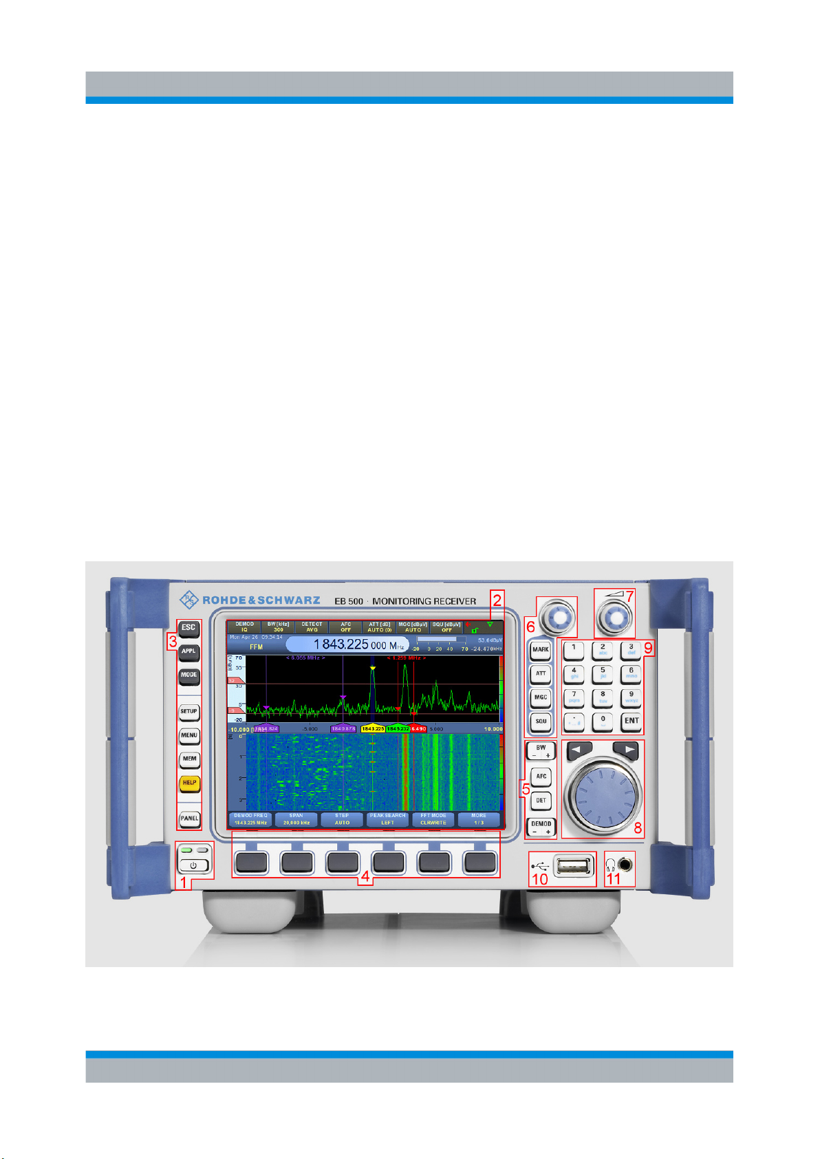
In the following overview the index numbers refer to the labels in the figure above.
1. Standby key with Ready (green) / Standby (amber) LED indicators.
13Getting Started 4072.8432.02 ─ 04
Page 14

R&S® EB500
Front-Panel Tour
2. 5.7", 640 x 480 pixels color TFT display.
3. Utility keys.
ESC terminates an ongoing operation, e.g. by closing a dialog.
●
● APPL sets the R&S EB500 to a particular application mode -- Receiver, Video,
ITU (optional), Decode (optional).
Operation
● MODE
the scanning modes.
SETUP provides access to the setup and configuration dialogs.
●
MENU provides access to operational functions "Snapshot", "Record", "Pre-
●
set", "Zoom +", "Zoom -", "Tests", "File" and "Sanitizing".
MEM provides a shortcut to memory-related dialogs: "Edit", "RCL", "Save" and
●
"Suppress".
● HELP starts the online help system (see chapter 2.3.3, "Online Help",
on page 32).
PANEL toggles between panels to make them active for softkey control.
●
4. Softkeys.
The function of each softkey is dependent on the softkey bar on the display.
5. Receiver Control Keys.
● BW selects the demodulation bandwidth (between 100 Hz and 5 MHz).
AFC switches automatic frequency control (AFC) ON or OFF.
●
changes the R&S EB500 from a Fixed Frequency Mode (FFM) to one of
DET selects the level measurement mode (AVERAGE, PEAK, FAST or RMS).
●
DEMOD selects the demodulation mode (FM, AM, PULS, PM, IQ, ISB, CW,
●
USB, LSB).
6. Select Rollkey & Control.
MARK selects the marker function. The rollkey is used to set marker positions
●
with associated softkeys. Pressing the rollkey toggles marker display.
ATT allows the rollkey to set the RF attenuation level. Pressing the rollkey tog-
●
gles between AUTO and manually set attenuation values.
MGC
●
ulation schemes. Pressing the rollkey toggles between AUTO (AGC) and MGC.
Gain control has no effect on FM and PM.
SQU allows the rollkey to set the squelch level. Pressing the rollkey toggles the
●
squelch activation.
allows the rollkey to set the demodulation level for amplitude related mod-
14Getting Started 4072.8432.02 ─ 04
Page 15

R&S® EB500
Operation
Front-Panel Tour
7. Volume Control Rollkey.
The volume of the speaker and headphones is adjusted with this knob. Pressing
knob will toggle the speaker mute. Headphones remain active when the speaker
the
is in mute position.
8. Cursor Left/Right & Main Rollkey.
Cursor LEFT/RIGHT moves the cursor in input fields and scrolls within lists. It
●
also step tunes the frequency by half of the span.
The main ROLLKEY or ROTARY KNOB is a weighted rotary knob which func-
●
tions primarily as a tuning knob. In certain menus, the main rollkey serves as
up/down
key. Pressing the rollkey confirms an entry (equivalent to the ENT key).
9. Data Entry Keys.
The 0~9 keys allow entry of the corresponding number or alphabet, decimal
●
point or symbol.
ENT (Enter) activates the editing mode and also confirms an entry.
●
10. USB 2.0 Port.
Allows a USB 2.0-compliant mouse, keyboard or storage device to be connected.
Maximum current
The maximum current for the USB port is 500 mA.
11. Headphones Jack.
Allows stereo headphones with a 3.5 mm stereo plug to be connected.
2.1.2 EB500 without front control panel
An
overview of the front-panel elements of the EB500 without front control panel is
given in the paragraph below.
15Getting Started 4072.8432.02 ─ 04
Page 16

R&S® EB500
Operation
Front-Panel Tour
In the following overview, the index numbers refer to the labels in the figure above.
1.
Standby key with Ready (green) or Fail (red) and Standby (amber) LED indi-
cators. The Ready LED also serves as Fail LED, as shown in chapter 1.2.7,
"STANDBY and READY", on page 10
2. Headphones Jack.
Allows stereo headphones with a 3.5 mm stereo plug to be connected.
GUI for remote access
A GUI for remote access is available for the Windows XP platform and is
particularly useful for the EB500 without front control panel because it gives
functionality similar to the EB500 with front control panel. Follow the instructions in chapter 4.4, "GUI Installation for Remote Access", on page 63 to
install the external GUI software. A Windows XP machine connected to the
same network as the EB500 without front control panel, is required.
16Getting Started 4072.8432.02 ─ 04
Page 17

R&S® EB500
Operation
Rear-Panel Tour
2.2 Rear-Panel Tour
The various inputs and outputs located on the rear panel of the R&S EB500 are
briefly explained in the paragraphs below.
In the following overview, the index numbers refer to the labels in the figure above.
1. X1 Power Supply.
Standard
Speakon NL4FX socket for DC power input. Socket accepts 10~32 VDC
on pin 1+ and ground on pin 1- of connector. Power requirement as indicated.
2. Antenna Inputs.
● X13 Antenna input for HF/V/UHF bands 9 kHz to 6 GHz.
● X14 Antenna input for HF band 9 kHz to 32 MHz.
3. X7 LAN Port.
A 10/100/1000Base-T port for remote control via LAN.
4. Miscellaneous I/O.
17Getting Started 4072.8432.02 ─ 04
Page 18

R&S® EB500
Rear-Panel Tour
X8 VIDEO A, X9 VIDEO B SMA outputs provide analog I-Q baseband or AM
●
FM demodulated signal for further processing. Can also be switched to out-
and
put-controlled analog intermediate frequency (IF) in two channels with an adjustable carrier frequency of 0 Hz to 70 MHz.
● X10 REF IN BNC input for synchronizing with an external 10 MHz reference
frequency normal.
● X11 REF OUT BNC output provides a 10 MHz reference frequency normal for
synchronization of other devices. Frequency normal dependent on selected
internal or external reference.
● X12 GPS/TR IN BNC input for an external 1 sec trigger pulse, e.g. from a GPS
device.
5. AUX / AUX Audio.
X3 AUX AUDIO is a 25-pin D-Sub female connector with the output of different
●
audio signals.
Operation
X4 AUX is a 25-pin D-Sub female connector for controlling external antenna
●
switching units.
6. X2 ANTENNA DF.
A 25-pin D-Sub female connector for controlling optional direction-finder antennas.
7. Serial Interfaces – EIA 232D Compatible.
X5 COM2, 9-pin D-Sub male connector.
●
X6 COM1, 9-pin D-Sub male connector.
●
X5 and X6 can be used for:
Serial GPS devices according to the NMEA0183 standard. Either one of the X5
●
or X6 connectors can be used for an external GPS device, to determine the
location and the exact time of the R&S EB500.
Serial compass devices according to the NMEA0183 standard. Use this con-
●
nector for an external compass device to determine the direction of your vehicle.
This will mostly be used in combination with direction finding (requires DF
upgrade R&S EB500-DF).
8. Grounding Post for Earth / Chassis Ground.
18Getting Started 4072.8432.02 ─ 04
Page 19

R&S® EB500
Operation
Graphical User Interface (GUI)
Signal Interfaces
All I/O, RF, signal interfaces (X2-X6, X8-X14) must be operated with double
shielded cables.
Interface X7 LAN
A CAT7 LAN cable must be used for this Gigabit capable interface.
2.3 Graphical User Interface (GUI)
This chapter provides a short description of the graphical user interface of the
R&S EB500.
2.3.1 GUI Layout
Following is an overview of the layout and individual elements of the graphical user
interface.
19Getting Started 4072.8432.02 ─ 04
Page 20

R&S® EB500
Operation
Graphical User Interface (GUI)
In the table below follows the description of the different panels, according to the
panel number indicated in the figure above.
Panel
No.
Description
1 Basic receiver parameters
2 Icons
Shows
the R&S EB500:
one or several of the following icons to indicate a specific function or condition of
Compass connected.
GPS connected.
Configuration: using external reference.
Receiver overflow.
Recording in progress.
Marker selected.
Speaker is off.
Speaker is on.
Audio signal is available in stereo at current frequency.
The R&S EB500 is not locked.
The R&S EB500 is locked by another client. Access is not possible.
The R&S EB500 is locked. Only the current operator can make changes
(exclusive write access).
A critical error occurred in the receiver. The "Test Points"
more information.
3 Mode
Shows the current receiver mode, e.g. FFM, PScan, FScan or MScan. The current date
and time is also shown.
4 Frequency
Shows the current receiver frequency. As this is the most important parameter, it is displayed much larger than the remaining parameters.
dialog will provide
20Getting Started 4072.8432.02 ─ 04
Page 21

R&S® EB500
Operation
Graphical User Interface (GUI)
Panel
No.
Description
5 Measurement parameters
Shows
bar graph). The squelch level is also shown by means of an indicating marker in the bar
graph.
6 Panel area
The panel area is used for displaying the various panels of the R&S EB500 (spectrum
and waterfall are shown).
●
●
●
7 Softkeys
Softkeys change their function based on the panel that is in focus. They show paneldependent parameters, e.g. "SPAN" and "STEP" for IF panel and IF Waterfall panel.
Other softkeys are only related to e.g. RF panel, RF Waterfall panel etc.
Softkeys
of the Utility keys is pressed or in case DET or MARK is pressed.
Softkeys can also provide the option for selecting a unit (kHz, MHz etc) e.g. when keyingin a frequency, they can provide additional functionality when editing input fields in dialogs, e.g. backspace or caps lock. Finally they can serve as shortcut keys for navigating
through tables in dialogs, e.g. in the "Memory Setup" dialog or through the "Help" pages.
the basic measurement parameters (level and frequency offset; numerically and
The light cyan color of the scale bar indicates that the panel is in focus: softkey
operations affect the panel (see below). A marker to show the squelch level relative
to the trace level is also displayed.
The dark blue bar around the demodulation frequency marking denotes the bandwidth being demodulated.
On the right side, the rainbow colored bar indicates the color that is mapped to the
corresponding spectrum level for the waterfall display.
can be related to hardkeys: they can e.g. provide selection options in case one
2.3.2
Turning on the R&S EB500 for the First Time
Upon power on, the R&S EB500 is always defaulted into the Fixed Frequency
Receiver Mode (reference to Operating Manual). In this mode, the R&S EB500
behaves as a normal receiver with the screen as shown in chapter 2.3.1, "GUI
Layout", on page 19. Upon power on the speaker will always be muted.
2.3.2.1 Unmute the speaker
The volume of the speaker and headphones is adjusted with the
VOLUME
KNOB. Pressing the knob will mute / unmute the speaker.
Headphones remain active when the speaker is in mute position.
21Getting Started 4072.8432.02 ─ 04
Page 22

R&S® EB500
Operation
Graphical User Interface (GUI)
2.3.2.2 Setting Date and Time
1. Press the SETUP key to open the Setup Menu.
Select the "Config" softkey to open the Configuration Menu.
2.
3. Select the "More 1 / 2" softkey.
4. Select the "Date & Time" softkey.
5. The dialog box for setting the date and time will appear. Set the appropriate date
and time using CURSOR LEFT / CURSOR RIGHT & ROTARY KNOB. "Backspace" can be found in the softkey bar whenever a field is in the edit mode. When
a field is in edit mode (whether it is minutes, seconds, hours etc), it will not be
updated. The R&S EB500 time will be set to the new time once the field gets out
of edit mode.
6. In the same dialog box there are fields to configure the time zone. Select "Set
Time Zone" to activate the newly configured time zone.
7. Next there are fields to set the time source.
8. The internal real-time clock will provide the time source at startup. In case a GPS
receiver is connected, the time source can be changed to GPS.
9. The last part of the dialog provides fields to retrieve the time from a Network
Time Server. Key-in the IP address of a Time Server, check the checkbox and
press "Get Time and Date" in order to get the time provided by the Time Server.
10. Press ESC to return to the previous menu.
22Getting Started 4072.8432.02 ─ 04
Page 23

R&S® EB500
Operation
Graphical User Interface (GUI)
Softkey fadeout
When the softkey options in the SETUP menu are not selected within 5 seconds, the menu will timeout and revert to the softkeys for the panel in focus.
In this situation, the setup procedure should be repeated from the start.
2.3.2.3 Short and Long Tests
The short and long test sequences are for verifying that the signal paths are functional.
1. Press the MENU key to open the "Menu" softkey bar.
Select the "More 1 / 2" softkey to open page 2 / 2.
2.
3. Select the "Tests" softkey to open the "Tests" softkey menu.
4. Select the "Short Test" softkey to run the short test sequence. The short test will
take about a second to produce a result. If the test passed, the result is as shown.
5. Select the "Long Test" softkey to run the long test sequence. In the long test
sequence, all the RF paths are tested. The test will take about 30 seconds to
complete. If the tests passed, the result is as shown. Otherwise, contact qualified
Rohde & Schwarz service personnel.
2.3.2.4 Settings – Receiver and Antenna
Before proceeding with the Basic Operation section, it is useful to install a suitable
antenna or signal source into the X13 ANT V/UHF connector on the rear panel.
23Getting Started 4072.8432.02 ─ 04
Page 24

R&S® EB500
Operation
Graphical User Interface (GUI)
Check the following settings under the Receiver and Antenna submenu to ensure
the default settings are in place.
Press the SETUP key to open the Setup Menu.
1.
2. Select the "Receiver" softkey.
3. The Receiver Configuration dialog box will appear. Check that "RF Mode" =
Normal, "Reference Mode" = Internal. Refer to the R&S EB500 Operating Man-
ual for the detailed description of this dialog box.
4. Press the ESC key to exit the dialog box and return to the Setup Menu.
5. Select the "Antenna" softkey.
6. The Antenna Control dialog box will open.
7. The "Automatic Control" checkbox is checked by default. When it is unchecked,
the antenna settings will be available for manual configuration. The Operating
Manual explains how this can be done. If HF option is present, HF Tuner Limit
sets the upper frequency limit of the direct reception HF tuner. Frequencies
above this limit will undergo a 2- or 3-stage heterodyne receiver path.
8. Press ESC to exit the dialog box and again to get to the top menu.
2.3.2.5 Basic Operation - Fixed Frequency Mode (FFM)
Operating in the top menu, the screen and softkeys are as shown in chapter 2.3.1,
"GUI
Layout", on page 19. Ensure the panel focus is on the Spectrum display (press
PANEL until the IF panel gets a light blue y-axis).
24Getting Started 4072.8432.02 ─ 04
Page 25

R&S® EB500
Graphical User Interface (GUI)
1. Tuning the Mid Frequency can be performed via:
ROTARY KNOB – the tuning step is defined in the "STEP" softkey menu.
a)
b) CURSOR LEFT / CURSOR RIGHT Key – the tuning step is half the
"SPAN" width defined in the softkey menu.
c) Data Entry Keys – Direct entry of the frequency is possible. The Mid Fre-
quency dialog box appears upon keypress and the softkey menu switches
into editing mode with different units and backspace.
2. The FFT Mode softkey allows the FFT trace to be displayed in the following
modes:-
Operation
25Getting Started 4072.8432.02 ─ 04
Page 26

R&S® EB500
Graphical User Interface (GUI)
a) "MINIMUM": the minimum of the FFT trace over time is displayed.
"MAXIMUM": the maximum of the FFT trace over time is displayed.
b)
c) "AVERAGE": the average of the FFT trace over time is displayed.
d) "CLRWRITE": the instantaneous FFT is displayed without averaging.
3. The Demodulation Frequency softkey allows a small portion of the displayed IF
Span to be selected for demodulation.
Operation
a) Select the "DEMOD FREQ" softkey to highlight it.
With the softkey in (3a) highlighted, follow procedure (1) to change the
b)
demodulation frequency within the IF span.
c) The Mid Frequency will not change.
4.
The Receiver Control Keys (chapter 2.1, "Front-Panel Tour", on page 13
Receiver Control Keys) allow changes to various receiver parameters.
26Getting Started 4072.8432.02 ─ 04
Page 27

R&S® EB500
Operation
Graphical User Interface (GUI)
a) The BW +/- key changes the demodulation bandwidth and the dark blue
region displays the bandwidth in relation to the IF span.
b) The AFC
demodulation bandwidth (3), AFC helps to track and keep the demodulation
frequency tuned to the frequency of the peak. AFC does not function in SSB
(USB or LSB) demodulation mode (4d).
c) The DET key changes the level detection mode (Average, Peak, Fast, RMS)
of the RF amplitude envelope.
d) The DEMOD +/- key changes the demodulation mode (CW, LSB, USB, ISB,
AM, FM, Pulse, PM, IQ). CW, USB and LSB demodulation modes are only
available with demodulation bandwidths (4a) of 9 kHz or narrower.
5.
The SELECT Rollkey & Control (chapter 2.1, "Front-Panel Tour", on page 13)
allows changes to various receiver functions.
key toggles automatic frequency control. When a peak is within the
27Getting Started 4072.8432.02 ─ 04
Page 28

R&S® EB500
Operation
Graphical User Interface (GUI)
a) The MARK
two sets of X markers and one set of Y markers to be set.
b) When the marker set is selected, turning the SELECT rollkey will move the
selected marker highlighted in green as illustrated above. The selected
marker can be toggled by pressing the "X1 / X2", "X3 / X4" or "Y1 / Y2"
softkey.
c) Pressing the SELECT rollkey (5g) toggles the selected set of markers on and
off.
d) The ATT
key (5g) toggles between automatic and manual attenuation. When in manual attenuation mode, turning the SELECT rollkey (5h) will allow the manual
attenuation level to be set.
key enables the marker function. The "Marker" softkey bar allows
key selects the RF attenuation function. Pressing the SELECT roll-
28Getting Started 4072.8432.02 ─ 04
Page 29

R&S® EB500
Graphical User Interface (GUI)
e) The MGC key selects the modulation gain control for amplitude modulated
modes. Pressing the SELECT rollkey (5g) toggles between automatic and
manual gain control. When in manual gain control mode, turning the
SELECT rollkey (5h) allows the manual gain control value to be set.
f) The SQU
(5g) toggles squelch on and off. When squelch is on, turning the SELECT
rollkey (5h) sets the squelch level.
The selected field for ATT, MGC and SQU is highlighted in yellow with the text
in inverse color as illustrated (ATT set to AUTO).
6. Configuring the display scale for IF panorama.
key selects the audio squelch control. Pressing the SELECT rollkey
Operation
a) Select the "More 1 / 4", followed by "More 2 / 4" and "More 3 / 4" softkeys
until page 4 / 4 of the menu.
b)
Select the "CONFIG IF PAN" softkey.
29Getting Started 4072.8432.02 ─ 04
Page 30

R&S® EB500
Operation
Graphical User Interface (GUI)
c) The IF Panorama dialog box will open. Change some of the settings and
observe how the IF Panorama is displayed.
- The first few fields allow to adjust the highest and lowest level to be displayed
in the IF panel. Pressing "Adjust Level Range" will perform a autoscal-
ing, optimized for the current spectrum.
- "Hold Max" enables the maximum of the trace to be displayed and held for
the specified duration.
- "Show Grid" displays grid lines over the spectrum window.
- "Waterfall Color Set" allows the choice of 4 color palettes for the mapping
of the trace level to the color on the waterfall display.
- "Highest / Lowest Level" sets the maximum and minimum of the vertical
scale respectively. This changes the scale of the displayed trace and hence
also the waterfall color mapping because the color is mapped relative to the
window height and not the absolute scale.
- The remaining fields are used to configure the polychrome settings. Please
refer to the operating manual to learn more about the polychrome representation of the IF spectrum.
2.3.2.6 Advanced Operation – FSCAN (Frequency Scan)
Frequency scan allows the monitoring of a frequency span greater than the realtime IF spectrum bandwidth.
1. Press the MODE key to open the Mode menu.
30Getting Started 4072.8432.02 ─ 04
Page 31

R&S® EB500
Graphical User Interface (GUI)
2. Select the "SCAN" softkey and select "FSCAN". The panel layout will change
that a RF panorama is included. The softkeys in the Mode Menu will change
so
according to the scan type selected. The mode is also displayed below the current date & time.
3. Press the ESC key to go back to the top menu. Ensure panel focus on the RF
Panel. Use the PANEL key to change if required. The softkey menu will be
available for the RF Panel and the Frequency Scan function.
4. Use "START", "STOP" and "STEP" or "CENTER", "SPAN" and "STEP" softkeys
to define the range and frequency step of the scan. In this example, start and
stop frequencies are set to 20 MHz and 200 MHz, respectively, with a step of
100 kHz.
5. The time it takes to acquire a frequency point is determined by the "Dwell
Time", "No Signal Time" and "Measurement Time" settings. For details refer to
the Operating Manual.
Operation
6. The "CONFIG RF PAN" softkey can be used to set the scale as per the "IF Panel
Config" softkey in chapter 2.3.2.5, "Basic Operation - Fixed Frequency Mode
(FFM)", on page 24.
7. Press the MODE key again to open the Mode Menu.
8. Select
the date and time will change from "FScan Stop" to "FScan" to show that FScan
is running.
the "Run +" softkey to start the frequency scan. The Mode display below
31Getting Started 4072.8432.02 ─ 04
Page 32

R&S® EB500
Operation
Graphical User Interface (GUI)
9. The RF spectrum and waterfall display are updated as the frequency sweeps
upwards. If "Run -" is selected instead, the frequency will sweep downwards.
Some of the parameters in the panel softkey menu (4 / 5) will be grayed out
when
the scan is running. To stop the scan, press the MODE key and select the
"Stop" softkey.
2.3.3 Online Help
All the information from the operating manual can be shown on the display of the
R&S EB500 after pressing the HELP key (or F1 for users of an external GUI).
This key is used to open the online help system. The "Help Assis-
tant" dialog supplies context-sensitive help, i.e. information related
to the context within which the HELP key is pressed (e.g. if HELP is
pressed while scanning, then scan-related help-pages will appear; if HELP is
pressed while conducting ITU measurements, then ITU-related help-pages will
appear).
32Getting Started 4072.8432.02 ─ 04
Page 33

R&S® EB500
Graphical User Interface (GUI)
The Help Assistant comprises three components:
The browser (at the right)
●
The help navigator (at the left)
●
The "look for" field (at the top left)
●
Navigation in the help system differs from navigation in all other dialogs. Pressing
the ENTER key or the main ROLLKEY takes you directly from the activated navigator
the components.
to the browser. Just like in any other dialog, the focus can be on either one of
Use the PANEL key to move the focus from one component to
another component.
ESC will close the dialog.
Browser
Operation
The browser (which works like a normal web browser) shows the actual help topics.
If the browser is selected but not yet active, it has a normal blue border. To activate
the browser, press the ENTER key, the ROLLKEY or click the mouse wheel. An
active browser is indicated by a thin blue frame. Use the ROLLKEY to scroll up and
down. Use the CURSOR LEFT / CURSOR RIGHT keys to scroll left and right. Step
through the page from hyperlink to hyperlink by pressing "Next Link". Pressing
ENTER or the ROLLKEY opens the selected link.
Navigator
The Navigator allows you to navigate through the help content. There are three ways
in which this navigation can take place: by content, by index and by search, based
on a search term. See below for more details.
Look For
The "Look For" field is provided for entering a search term, when navigating in the
"Search" mode.
Softkeys
Regardless of which component is selected, you can use the softkeys at the bottom
of the display to browse the documentation.
33Getting Started 4072.8432.02 ─ 04
Page 34

R&S® EB500
Graphical User Interface (GUI)
The left three keys of the softkey bar decide on the type of navigator.
If "Content" is pressed, the navigator changes to "Content" mode.
In this mode, you can browse the table of contents.
If "Index" is pressed, the navigator changes to "Index" mode. This
allows
sorted alphabetically, as shown in the figure below).
you to browse the documentation by index (index entries are
Operation
In "Index"
acters of a index term, as shown above, you can speed-up the search.
search.
In "Search" mode the "Look For" field must be activated and the keyword should be
entered there. Then, by pressing the ENTER key or the ROTARY KNOB, the navigator will list all the pages that have a reference to this keyword.
mode the "Look For" field can be activated: by entering the first few char-
If "Search" is pressed, the navigator changes to "Search" mode. In
this mode, the help content can be accessed based on keyword
34Getting Started 4072.8432.02 ─ 04
Page 35

R&S® EB500
Operation
Graphical User Interface (GUI)
For all three modes, after pressing the ENTER key or the ROTARY KNOB, the
browser will show the page that was selected.
The "Zoom" key provides 5 different zoom levels: by repeatedly
pressing the "Zoom" key the browser will display the content from
minimum to maximum zoom.
Help Assistant at minimum zoom. Help Assistant at maximum zoom.
The two keys at the right side of the softkey bar are provided to facilitate the browsing.
By pressing the "Next Link" key you can step through the browser
from
one hyperlink to another hyperlink. The focus will immediately
switch to the browser once "Next Link" key is pressed. By pressing ENTER or
ROTARY KNOB you can browse into the hyperlink just like in a normal web browser.
35Getting Started 4072.8432.02 ─ 04
Page 36

R&S® EB500
Operation
Options for the R&S EB500
After browsing through the content by using the "Next
Link" you can
always go back to any of the previous pages by pressing the
"Back" key.
2.4
Options for the R&S EB500
In the R&S EB500, additional features can be enabled by using options and
upgrades. Options can be purchased together with the R&S EB500 or at any time
after that. Apart from options there are also upgrades. Currently there is only one
upgrade
available: the DF-upgrade: an existing R&S EB500 can be upgraded to get
the same features as a R&S DDF205. A brief description of the available options
and upgrades are listed below.
2.4.1
Panorama Scan ( R&S EB500-PS)
The R&S EB500-PS "Panorama Scan (PSCAN)" function is used to perform an
ultra-quick
scan of a user-definable frequency range. It thus provides a quick overview of the spectrum occupancy. Changes caused by illegal radio services, interferences, transient emissions etc. can immediately be seen at a glance. The
R&S EB500 can be switched to "listen" mode simply by pressing a key. The signal
of interest can be selected, demodulated and analyzed by using the demodulation
frequency.
Refer to the operating manual for a detailed explanation.
2.4.2
ITU Measurement ( R&S EB500-IM)
With SW option R&S EB500-IM (ITU-Measurement) installed, the measurement
functions "AM modulation index", "FM frequency deviation", "PM phase deviation"
and "bandwidth measurement" are available in addition to level and offset measurement.
Refer to the operating manual for a detailed explanation.
36Getting Started 4072.8432.02 ─ 04
Page 37

R&S® EB500
Operation
Options for the R&S EB500
2.4.3
HF Frequency Range Extension ( R&S EB500-HF)
This is a hardware option: it requires a HF preselector board to be installed. With
HF option installed, signals from 9 kHz to 32 MHz can be obtained (which covers
the
the full HF range from 3 MHz to 30 MHz).
Refer to the operating manual for a detailed explanation.
2.4.4
SHF Frequency Range Extension ( R&S EB500-FE)
The FE option provides an extended frequency range from 3.6 GHz to 6 GHz.
Refer to the operating manual for a detailed explanation.
2.4.5
Direction Finding ( R&S EB500-DF)
In addition to detection, the direction from which the signal originates is also an
important criterion in radiomonitoring. When the DF upgrade R&S EB500-DF is
added, the R&S EB500 can be used as a single-channel direction finder. The DF
upgrade
consists of an installation kit for the R&S EB500. The corresponding direc-
tion-finding antenna must be selected separately.
Below follows a short explanation showing step-by-step how to achieve the required
settings in the configuration when connecting a DF antenna and how to use the
direction finder to locate the origin of a signal. Refer to the operating manual for a
detailed explanation.
2.4.5.1 Direction Finding Setup and Procedure
In the steps described below, it is presumed that R&S ADD197 and R&S ADD 075
Direction Finding antennas are installed with built-in compass R&S GH150 in a stationary system
37Getting Started 4072.8432.02 ─ 04
Page 38
R&S® EB500
DF Antenna and Compass Setup
Operation
Options for the R&S EB500
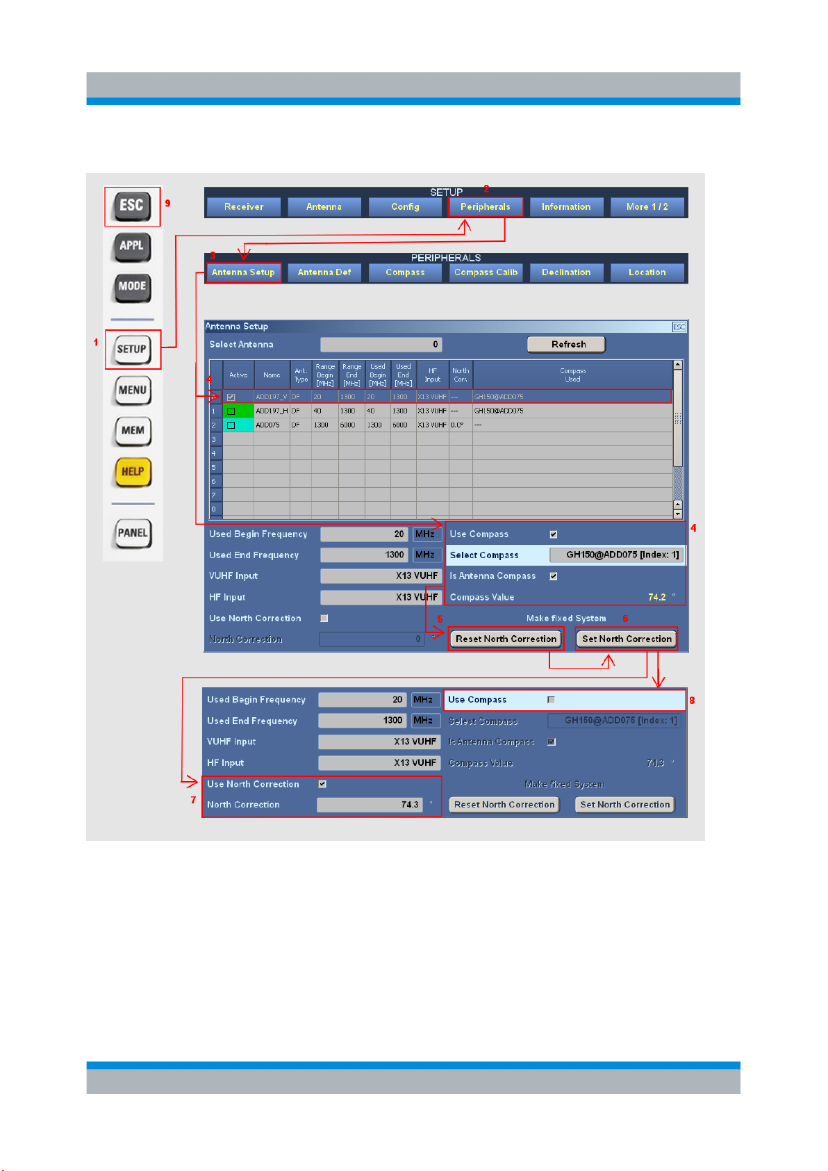
1. Press the SETUP key.
2.
Press "Peripherals" softkey to open the "Peripherals" selectors.
3. Open the Antenna Setup dialog.
4. The dialog shows the DF antenna ADD197. Check "Use Compass" and select
the built-in compass GH150. Take note of the compass reading.
Press "Refresh" if the antenna does not show up in the table.
38Getting Started 4072.8432.02 ─ 04
Page 39

R&S® EB500
Options for the R&S EB500
5. Configure for a fixed system. For this reason use the compass reading to set
the North correction. First click "Reset North Correction"
6. After that click "Set North Correction".
7. The compass reading has been transferred to the antenna's North Correction.
8. The fixed system has been configured and the compass will be disabled.
9. Press ESC to close the dialog.
Direction Finding Procedure
Direction Finding operation mode, combined with a direction finding antenna, allows
identifying the origin of a signal: the direction from where a signal is transmitted.
.
Operation
1. Press the APPL key to open the application selection softkeys.
39Getting Started 4072.8432.02 ─ 04
Page 40

R&S® EB500
Operation
Options for the R&S EB500
2.
Press
"DF" to switch the R&S EB500 to DF mode. The panel layout will change
to the default direction finding layout with focus on DF IF Panel. Follow the steps
as explained in chapter 2.3.2.4, "Settings – Receiver and Antenna",
on page 23 to confirm that your DF antenna is installed properly and recognized
by the system.
3. Use the main ROTARY KNOB or the numeric keypad to select the frequency
for which you want to conduct direction finding as explained in chapter 2.3.2.5,
"Basic Operation - Fixed Frequency Mode (FFM)", on page 24. Switch to DF
mode.
4. Choose an appropriate combination of "SPAN", "STEP" and "selectivity" in order
to optimize the direction finding bandwidth so that it matches the channel spacing of the RF band that is being monitored.
5. Also, choose a sufficiently small DF measurement time so that the measurement
can take place within a short time-frame (this is in particular important when the
observation is done on a moving vehicle).
In case the measurement takes place on a stationary system, use the built-in
compass to configure North Correction, as explained in "DF Antenna and Com-
pass Setup" on page 38. Alternatively use a standalone compass and manually
key-in the North Correction.
6. Use the PANEL key to change the focus to the Polar Panel
7. Set the DF Quality threshold to a value reasonably high so that reliable DF
measurement can be achieved for the channel that is being investigated.
8. Now the direction finding will most likely produce reliable bearing results, visible
by the stationary position of the yellow bearing arrow in the wind rose. The
heading indicator (white-color vane) in the wind rose corresponds with the compass value.
2.4.6
Selective Call ( R&S EB500-SL)
The R&S EB500-SL option can be used to decode selective-call methods and to
demodulate pagers. The following selective-call methods are supported: CCIR1,
CCIR7, CCITT, EEA, EIA, EURO, DCS, DTMF, CTCSS, NATEL, VDEW, ZVEI1,
ZVEI2.
Refer to the operating manual for a detailed explanation.
40Getting Started 4072.8432.02 ─ 04
Page 41

R&S® EB500
Operation
Options for the R&S EB500
2.4.7
With R&S EB500-DDC
Digital Down Converter ( R&S EB500-DDC)
the R&S EB500 becomes a multi-channel receiver. In addi-
tion to the basic receiver channel, another three receive channels are available.
These receive channels are realized with Digital Down Converters (DDCs) within
the IF bandwidth. Each DDC can demodulate AM, FM, PM, PULSe or IQ up to a
bandwidth of 1 MHz and CW, LSB and USB up to a bandwidth of 9 kHz. An independent audio volume and balance for each DDC as well as for the basic receiver
channel enable flexible audio mixing and recording. The DDC frequencies can be
set independently or coupled to the basic receiver frequency. The demodulation
parameters "Demodulation Mode", "Bandwidth", "Squelch state" and "Squelch
threshold" can also be set independently or coupled to the corresponding receiver
parameters.
The steps below will guide you through a typical scenario when using Digital Down
Converters.
41Getting Started 4072.8432.02 ─ 04
Page 42

R&S® EB500
Operation
Options for the R&S EB500
2.4.7.1 Using Digital Down Converters
42Getting Started 4072.8432.02 ─ 04
Page 43

R&S® EB500
Options for the R&S EB500
1. Press the APPL key to open the application selection softkeys.
2.
Press "DDC" to switch the R&S EB500 to DDC mode. The panel layout will
change to the default DDC layout with focus on DDC Panel.
Operation
3. Use
the arrow keys to change the focus from one DDC channel to another DDC
channel
4. For as long as the DDC Panel has the focus, the MAIN ROLLKEY,
BANDWIDTH key, DEMOD key and SQUELCH key will operate on the DDC
channel.
5. Use the "Show On" softkey if you want to see the DDC demodulation parameters
in the IF Panorama
6. Use the PANEL key to change the focus to the IF Panorama. The DDC band-
width of the DDC channels are visible by a dark red bar. Note that the DDC
channels must be within the span.
7. If you want to couple demodulation mode of a particular DDC channel with the
main IF then press the "DEMOD" UNCOUPLED / COUPLED softkey. Take note
that not all bandwitdhs and demodulation modes are available for DDC, so the
coupling might not work.
8. If you want to couple frequency of a particular DDC channel with the main Fre-
quency then press the "FREQ" UNCOUPLED / COUPLED softkey
9. Use the "Config DDC" softkey to open the DDC configuration dialog. The audio
settings of individual DDC channels can be controlled, using the sliders, selectors and check boxes in this config dialog.
2.4.8
Wideband Direction Finding ( R&S EB500-WDF)
A prerequisite for the R&S EB500-WDF option is that the DF upgrade must be
installed.
With the R&S EB500-WDF installed, all the DF-related features are acces-
sible through the WDF application mode.
The Wideband Direction Finding option will give bearing results not only for the
center frequency but for all frequencies within the real-time bandwidth. The bearing
is shown in an azimuth panel. This is a panel which shows the bearing between 0
and 360 degrees plotted in a gray scale in which older signals appear in darker
shade of gray and newer signals in a lighter shade of gray.
43Getting Started 4072.8432.02 ─ 04
Page 44

R&S® EB500
Options for the R&S EB500
WDF Application Mode
the DF-related features are accessible through the WDF application mode.
All
Refer to the operating manual for a detailed explanation.
Operation
2.4.9
Correction Data ( R&S EB500-COR)
Correction data is used to compensate for certain factors which have their origins
outside
the R&S EB500 and affect the measurement results. The correction data is
stored within the flash file system of the R&S EB500.
The R&S EB500-COR can process the correction data for correcting Antenna factors, cable attenuation, azimuth correction and omniphase correction.
Refer to the operating manual for a detailed explanation.
44Getting Started 4072.8432.02 ─ 04
Page 45

R&S® EB500
Maintenance
Cleaning
3 Maintenance
3.1 Cleaning
Clean the outside of the R&S EB500 using a soft, lint-free dust cloth.
Damage caused by cleaning agents
Cleaning agents contain substances that may damage the R&S EB500, e.g.
solvent-containing cleaning agents may damage the front panel labeling or
plastic parts. Never use cleaning agents such as solvents (thinners, acetone,
etc), acids, bases, or other substances.
3.2 Storing and Packing
The R&S EB500
can be stored at the temperature range quoted in the specifications
(check the "Service" section in the Operating Manual). When it is stored for a longer
period of time the R&S EB500 should be protected against dust. The original packing should be used, particularly the protective caps at the front and rear, when the
R&S EB500 is to be transported or dispatched. If the original packing is no longer
available, use a sturdy cardboard box of suitable size and carefully wrap the
R&S EB500 to protect it against mechanical damage.
3.3 Test Points
There are voltage and temperature checks at many test points of the R&S EB500
modules. Some of these test points depend on each other. The error messaging
system
considers these dependencies and reports only the causal source of errors.
A detailed guideline describing how to read each of the test points can be found in
the "Maintenance" section of the Operating Manual.
45Getting Started 4072.8432.02 ─ 04
Page 46

R&S® EB500
Test points
The test points are mainly for diagnostic purposes and their interpretation
should be left to qualified Rohde & Schwarz service personnel.
Maintenance
Test Points
46Getting Started 4072.8432.02 ─ 04
Page 47

R&S® EB500
Software and Firmware Update
Retrieve Firmware and GUI Versions
4 Software and Firmware Update
4.1 Retrieve Firmware and GUI Versions
The following key sequence allows to retrieve the various firmware revisions of the
R&S EB500.
The "Firmware Version" refers to the version of the firmware which runs on the main
processor board. It provides the main control functions of the receiver.
The “GUI Version” refers to the GUI software in use:
If the menu is obtained from the EB500 with front control panel, it refers to the
●
Front Panel GUI.
If the menu is obtained from Remote Access, it refers to the Remote Access
●
GUI.
The
GUI software runs on its own processor on the frontpanel hardware. This processor is different from the one on the main processor board and has its own operating system, which is different from the receiver firmware.
The "DSP Version" and "FPGA Version" are part of the firmware image and cannot
be updated separately.
47Getting Started 4072.8432.02 ─ 04
Page 48

R&S® EB500
Software and Firmware Update
Receiver Firmware and GUI Update for EB500 with front control panel
The "Boot Program Version" refers to a stand-alone program whose only purpose
is to boot-up the R&S EB500.
For EB500 with front control panel, it is therefore sufficient to update the receiver
firmware
and GUI software: this will update all the images required for normal operation to the latest versions. The receiver firmware and GUI software will be updated
in the same procedure. This keeps the update process simple and prevents any
version conflict.
For EB500 without front control panel only the receiver firmware needs to be updated.
CD-ROM and Downloads
The R&S EB500 is shipped together with a “EB500 Software and Documentation CD ROM” which contains the same firmware and GUI versions as in
the R&S EB500 at the time of shipment. The latest versions can be downloaded from GLORIS.
The CD-ROM will autostart and launch the opening menu where the various
options are available. If the CD-ROM does not autostart or if the files are
obtained from the company website, launch the menu by running the
start.htm in a suitable browser. Recommended is
Internet Explorer 7.
The next few sections explain the steps needed for updating the receiver firmware
and GUI software (for EB500 with front control panel) or only the receiver firmware
(for EB500 without front control panel) respectively.
4.2 Receiver Firmware and GUI Update for EB500
with front control panel
The update process for the EB500 with front control panel is a combined procedure
which updates the receiver firmware and GUI software in one single process. This
process makes it transparent for the user which component is actually being updated and version conflict will be avoided.
48Getting Started 4072.8432.02 ─ 04
Page 49

R&S® EB500
Receiver Firmware and GUI Update for EB500 with front control panel
Software and Firmware Update
4.2.1 Preparations
Required files and accessories
You will need the following files and accessories to perform an update:
A self-extracting EB500 installation file.
●
USB flash drive with at least 256 Mb free space (A new or formatted one is
●
recommended). The MBR (Master Boot Record) of the flash drive will be overwritten to make it bootable.
Prepare USB Flash drive
The update process is done from the USB flash drive. The R&S EB500 boots up
from the USB flash drive, and the update continues from there.
The following steps are necessary for installing files on the USB flash drive:
● Obtain the R&S EB500 update installation file. This file can be retrieved from
either one of the locations mentioned at "CD-ROM and Downloads"
on page 48.
the USB flash drive into a USB port of the PC (or Notebook). Take note of
Plug
●
the drive letter assigned to this USB flash drive.
Execute the installation by clicking on Receiver Firmware and GUI
●
Installation. Allow access if there are security warnings. The dialog box
shown below will appear. It will ask for the path of the USB flash drive. Check
the drive letter before clicking "OK". This must be the drive letter which is
assigned to your USB flash drive after plugging it into your Windows host.
SFX image on USB Flash drive
This installer is built as a compressed SFX image. This is a self-extracting
image
which will install on the storage destination that is given as parameter:
here it is the USB flash drive. The image also contains a MBR section so that
it can boot-up from the USB flash drive.
Not every USB flash drive can be converted into a bootable drive. If a flash
drive still cannot boot-up after following the procedures above then it is
advised to change to a different brand USB flash drive.
49Getting Started 4072.8432.02 ─ 04
Page 50

R&S® EB500
Receiver Firmware and GUI Update for EB500 with front control panel
SFX Installer
Be careful to use the correct drive letter that is assigned to the flash drive (e.g.
F: or G:). If a wrong drive letter is used (e.g. C:), the boot-loader might get
accidentally installed on the host system, which will result in a unusable host.
Software and Firmware Update
After double-checking the drive letter and clicking "OK", the SFX image will selfextract to the USB flash drive. This process will take less than one minute for a
USB 2.0 drive. In case a USB 1.1 flash drive is used it will take much longer.
The last step for the SFX installer is copying the MBR section to the USB flash drive.
This is shown in a console window.
50Getting Started 4072.8432.02 ─ 04
Page 51

R&S® EB500
Software and Firmware Update
Receiver Firmware and GUI Update for EB500 with front control panel
After the console window has closed, the USB flash drive can be removed. It now
contains the updated installation file.
4.2.2 Update Procedure
Power off the R&S EB500, plug-in the USB flash drive into the USB port on the
R&S EB500 front-panel and restart.
Wait for the R&S logo to appear and press ESC
to go into the boot menu. In the
boot-up screen that follows, use the arrow keys on the front-panel to move to "Hard
Disk" (see screenshot below) and press ENT.
51Getting Started 4072.8432.02 ─ 04
Page 52

R&S® EB500
Receiver Firmware and GUI Update for EB500 with front control panel
If the USB flash drive can be detected by BIOS, as shown in the screenshot below,
select the USB flash drive as the "Boot First" device.
Software and Firmware Update
If BIOS does not recognize the USB flash drive, select "Bootable
press ENT to enable booting from the USB flash drive.
The first boot device, which starts with "Ch2 S" is the internal drive of the
R&S EB500. If this is selected by mistake, the R&S EB500 will start up as normal
and the GUI Update procedure should be restarted.
In the next dialog select "Update" using the CURSOR LEFT / CURSOR RIGHT or
ROTARY KNOB and the ENT key. See chapter 2.1, "Front-Panel Tour",
on page 13.
Erasing the Data Partition
The
Update utility also has an option to erase the data partition, according to
DoD 5220.22-M standard. This method is irreversible. Refer to the Operating
Manual for more details.
Add-in Cards" and
52Getting Started 4072.8432.02 ─ 04
Page 53

R&S® EB500
Receiver Firmware and GUI Update for EB500 with front control panel
Fig. 4-1: EB500 System Update
Uninterrupted Power
From this point onwards, ensure that power to the R&S EB500 is not interrupted. Failing to do so might result in a non-functional front panel.
Software and Firmware Update
The updater will then check if the FPC2 firmware (for the frontpanel key controller)
needs to be updated. FPC2 firmware will only be updated when the version on the
USB flash drive is newer than the version currently installed.
FPC2 Update
Do not interrupt the updating of the FPC2 firmware (e.g. removing the USB
flash drive or resetting the R&S EB500). Keys on the front-panel might
become unusable if the updating process were interrupted.
Should
the keys on front panel become unusable (not responsive), an external
keyboard (and a USB hub) would be needed to redo the FPC2 update.
Finally the actual update of the receiver firmware and the GUI software can start.
The
update process can cater for more than one image. If the update was installed
on a USB flash drive that was previously used for updates, the menu below will
show more than one installer image. Use the ROTARY KNOB to select an image
and press ENT.
53Getting Started 4072.8432.02 ─ 04
Page 54

R&S® EB500
Receiver Firmware and GUI Update for EB500 with front control panel
Version of Updater Program
Software and Firmware Update
Make
the version of the firmware image you want to install. The version of the
updater program is shown in the dialog title of the first dialog.
If for some reason the version of the R&S EB500 updater program is lower
than the firmware you want to install (e.g. because you installed an older version of the firmware), just copy again the update installation file to the USB
flash drive, following the steps explained in chapter 4.2.1, "Preparations",
on page 49. This will overwrite the original updater program so that both the
firmware and the updater program have the same version on the USB flash
drive.
sure that the version of the updater program is the same or higher than
One image will contain an updated version of the receiver firmware as well as the
GUI. The receiver firmware will be updated first. The firmware will be copied from
USB flash drive to EEPROM on the processor board. The EEPROM needs to be
erased first, after which the program code will be downloaded and the checksum
calculated.
54Getting Started 4072.8432.02 ─ 04
Page 55

R&S® EB500
Receiver Firmware and GUI Update for EB500 with front control panel
Flash erase and update
While updating a R&S EB500, portions of the flash memory will be erased.
erase process may take up to two minutes, after which the new firmware
This
will be loaded. This will usually take about one minute. The update progress
is visualized by means of notification dialogs and progress bars.
Then, while the receiver resets, the GUI will be updated. The GUI runs on a dedicated processor (IPS1) and has its own operating system. This processor also
needs to reboot once the update completed.
At the end of the process, when the dialog below is shown, press ENT to reboot.
Now both the receiver firmware and the GUI are updated with the latest version.
This can be verified after reboot by following the steps shown in chapter 4.1,
"Retrieve Firmware and GUI Versions", on page 47.
Software and Firmware Update
If update procedure fails.
If
the update procedure fails, simply switch off the R&S EB500 and restart the
update procedure.
Updating the EB500 without front control panel
The EB500 without front control panel cannot be updated with this method.
order to update the receiver firmware of a EB500 without front control panel,
In
you will need the Update32 tool. The method of updating by using the
Update32 tool is described in chapter 4.3, "Receiver Firmware Update for
EB500 without front control panel", on page 56.
55Getting Started 4072.8432.02 ─ 04
Page 56

R&S® EB500
Software and Firmware Update
Receiver Firmware Update for EB500 without front control panel
Remote GUI on Notebook / desktop PC
you want to install the GUI for use on a notebook or desktop PC, you should
If
follow the procedure described in chapter 4.4, "GUI Installation for Remote
Access", on page 63.
If the R&S EB500 cannot reboot
Due
to the fact that the R&S EB500 also can be updated using the Update32
Tool (see "Updating the EB500 with front control panel" on page 63), there
is a chance that the R&S EB500 cannot reboot. Follow the steps described
in "If the R&S EB500 cannot reboot" on page 63 to deal with this problem.
4.3 Receiver Firmware Update for EB500 without front control panel
This model requires a different update method which makes use of the LAN interface of the R&S EB500 (X7 on the rear panel). The method uses the "Update32"
tool, which runs under Windows NT, Windows 2000 and Windows XP.
Retrieve Update32
The firmware required for the update can be retrieved from either one of the locations mentioned at "CD-ROM and Downloads" on page 48.
Click on Firmware Update Program and File Explorer will be launched into
the directory Update32XP. The Update32 tool can be installed by clicking on
Setup. If your browser does not launch File Explorer, you should launch it
manually and navigate to the Update32XP directory on the CD-ROM where you
can run Setup.
56Getting Started 4072.8432.02 ─ 04
Page 57

R&S® EB500
Software and Firmware Update
Receiver Firmware Update for EB500 without front control panel
Flash erase and update
While updating a R&S EB500, portions of the flash memory will be erased.
erase process may take up to two minutes, after which the new firmware
This
will be loaded. This will usually take about one minute for the R&S EB500.
The update progress is visualized by the progress bar of the "Update32" tool.
Interrupted Power to R&S EB500
Switching off the power supply during the update procedure is not recommended but will not harm the R&S EB500 as the "bootprog" is still available
for subsequent firmware update of the system.
4.3.1 Preparations
Checking the R&S EB500 firmware version number
Refer to the section chapter 4.1, "Retrieve Firmware and GUI Versions",
on page 47 to obtain the current version of the firmware in the R&S EB500, if necessary.
System requirements
For a firmware update you need:
An IBM-compatible PC running Windows NT, Windows 2000 or Windows XP
●
with LAN interface.
A standard LAN cable with RJ45 connectors.
●
"Update32" tool for Windows XP requires a WinPcap installation. Installing
The
●
the latest version of the tool will also install the version of WinPcap that is compatible with the version of the tool (please note the disclaimer and the information
in WinPcap's "About" box).
57Getting Started 4072.8432.02 ─ 04
Page 58

R&S® EB500
Software and Firmware Update
Receiver Firmware Update for EB500 without front control panel
Connecting the R&S EB500
Proceed as follows to connect the R&S EB500:
the LAN cable to connect the Ethernet port of your PC directly to LAN inter-
Use
●
face X7 of the R&S EB500 or
● Use the LAN cable to connect the LAN interface X7 of the R&S EB500 to a
network hub which is in the same LAN network as your PC.
Network adapters
If you have more than one network adapter in your computer, the "Update32"
tool will take the first as the default adapter and try to use it for the update. To
change the network adapter, select "Network Adapter" in the "Config" menu
of the "Update32" tool.
4.3.2 Firmware Update Using Update32 Tool
First steps
● Power
off the R&S EB500. It has to be switched on later in the update procedure.
● Make sure the R&S EB500 and the PC running the "Update32" tool are con-
nected either directly using a LAN cable or through the same network switch/
hub. It is NOT recommended that the PC and the R&S EB500 be connected
across different routers when performing firmware update with "Update32"
because special network packets required by the process may be discarded by
the router.
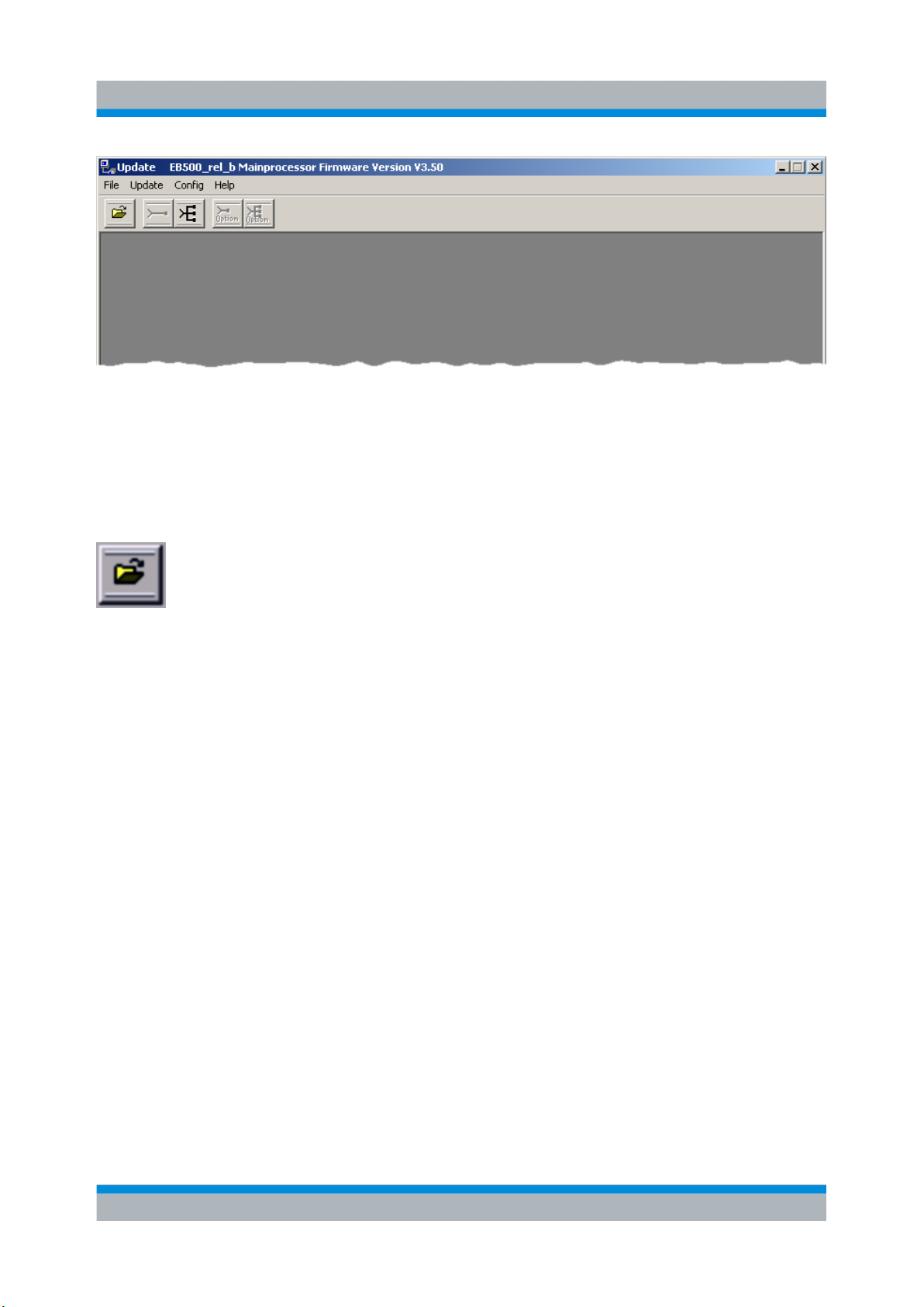
Run the "Update32" tool by clicking on Firmware Update Program. Allow
●
access if there are security warnings. Below is a screenshot of the Update32
application.
58Getting Started 4072.8432.02 ─ 04
Page 59
R&S® EB500
Receiver Firmware Update for EB500 without front control panel
Selecting the configuration file
Software and Firmware Update
● To
●
update a R&S EB500, the correct update configuration file has to be selected.
Click on the following button to open the corresponding dialog:
Navigate to the folder that contains the configuration files under the "Look in:"
field. Next, select the desired configuration file in the upper portion of the dialog
and click the "ACCEPT" button.
59Getting Started 4072.8432.02 ─ 04
Page 60

R&S® EB500
Software and Firmware Update
Receiver Firmware Update for EB500 without front control panel
Starting the update
Click on the "Update"
●
and the following dialog will appear.
button:
60Getting Started 4072.8432.02 ─ 04
Page 61

R&S® EB500
Software and Firmware Update
Receiver Firmware Update for EB500 without front control panel
● Switch ON the power to the R&S EB500 ("target") to be updated. After a short
period a new entry will be shown in the list of targets as shown in figure below.
Fig. 4-2: List of targets for Ethernet Communication
Select the desired target and click the
●
"Start" button.
Updating process
The following dialog appears when the update starts. In the process, the flash is
being erased and then the new firmware is loaded into the flash.
61Getting Started 4072.8432.02 ─ 04
Page 62

R&S® EB500
Receiver Firmware Update for EB500 without front control panel
Completing the update
Software and Firmware Update
After the update is completed, close the dialog by clicking on the
R&S EB500 will restart automatically.
If update procedure fails.
If
the update procedure fails, simply switch off the R&S EB500 and restart the
update procedure.
"OK" button. The
62Getting Started 4072.8432.02 ─ 04
Page 63

R&S® EB500
Software and Firmware Update
GUI Installation for Remote Access
Updating the EB500 with front control panel
The EB500 with front control panel can also be updated using the method
the Update32 tool. Please take note that this method cannot update the
with
GUI. This might cause version conflicts between receiver firmware and GUI.
For updating the EB500 with front control panel, use the method described in
chapter 4.2, "Receiver Firmware and GUI Update for EB500 with front control
panel", on page 48.
If the R&S EB500 cannot reboot
Because the Update32 Tool performs its firmware updates over the LAN,
there
could be a conflict if another user is running the tool in the same network.
The R&S EB500 might "hang" after a reboot because the bootloader gets
"trapped" by this Update32 on the network. In such cases the best advise is:
unplug the network cable during boot-up and find out who else is running
Update32 on the corporate network.
4.4 GUI Installation for Remote Access
This section explains how to install the Remote GUI for use on a notebook or desktop PC.
Internal installation
you want to install the GUI on the R&S EB500, follow the procedure descri-
If
bed in chapter 4.2, "Receiver Firmware and GUI Update for EB500 with front
control panel", on page 48.
4.4.1 Preparations
Required files and accessories
The
Remote Access GUI can be retrieved from either one of the locations mentioned
at "CD-ROM and Downloads" on page 48.
63Getting Started 4072.8432.02 ─ 04
Page 64

R&S® EB500
Software and Firmware Update
GUI Installation for Remote Access
Retrieving the IP address of a R&S EB500
is more convenient to use DHCP with the serial number of the R&S EB500.
It
For example, if the serial number is 100.001-002, the DHCP name will be "rseb500-100001-002". If DHCP is unavailable, it is advisable to run the
"Update32" tool as explained in: chapter 4.5, "Changing the IP Address",
on page 68 and assign a static IP address.
4.4.2 Installation Procedure
Execute
the Remote Access GUI installer by clicking on GUI Installation for
Remote Access on the html menu. Allow access if there are security warnings.
Uninstalling an earlier version of the GUI
If an earlier version of the GUI exists, it must be uninstalled before the installation
of a new GUI can proceed. A dialog will appear first, which requests to uninstall this
earlier version:
Click OK and wait for the uninstall to proceed.
Once uninstall is completed, the installation can go ahead. The first step is to keyin
the IP address and port number of the R&S EB500. You can find it under "Current
IP Address" and "Current Port" after opening the "Network Configuration" dialog
(SETUP > "Config" > "Network") on the front panel.
If your local network has a DNS server and you know the serial number of the
R&S EB500, it can be more convenient to use DHCP with the name under which
the R&S EB500 is known: for a R&S EB500 with serial number e.g. 100001-002 the
DHCP name will be: "rs-eb500-100001-002".
64Getting Started 4072.8432.02 ─ 04
Page 65

R&S® EB500
In the next step, choose the display resolution. Note that the resolution refers to the
panel
of your PC monitor must be higher than the size stated in the settings below, otherwise the buttons might not fit in the screen. A resolution of 800x600 will fit on most
monitors.
resolution. When the emulated front panel buttons are included, the resolution
Software and Firmware Update
GUI Installation for Remote Access
Finally configure the installation folder.
65Getting Started 4072.8432.02 ─ 04
Page 66

R&S® EB500
Installation will take a few minutes. Click "Next" when completed.
Software and Firmware Update
GUI Installation for Remote Access
The Remote Access GUI requires an additional "Redistributable" package, distributed by Microsoft for the deployment of certain software built for the Windows operating system. It is included in the installation file as well, so there is no need to
download it from the Microsoft website.
66Getting Started 4072.8432.02 ─ 04
Page 67

R&S® EB500
Click OK to install the "Redistributable" package. Installation will take a few minutes.
Software and Firmware Update
GUI Installation for Remote Access
Start the Remote Access GUI via "Start" ->
following dialog may appear due to the Windows Firewall. Click on "Unblock" to
allow the traffic to/from the R&S EB500
As a last step, you may have to change the Windows Firewall settings to enable the
network traffic of the R&S EB500 GUI. For this reason, start the GUI via "Start" ->
"Programs" -> " R&S EB500 GUI". When the GUI is displayed, the following dialog
may also appear.
"Programs" -> " R&S EB500 GUI". The
Click "Unblock"
R&S EB500 GUI.
and the Windows Firewall is set to enable the network traffic of the
67Getting Started 4072.8432.02 ─ 04
Page 68

R&S® EB500
Software and Firmware Update
Changing the IP Address
4.5 Changing the IP Address
4.5.1 Using Update32 Tool
The IP address of the R&S EB500 can be changed using the "Update32" tool. By
default, the R&S EB500 is shipped with DHCP enabled.
Refer to "Retrieve Update32" under chapter 4.3, "Receiver Firmware Update for
EB500 without front control panel", on page 56 to read the steps for retrieving and
running the "Update32" tool.
Starting the procedure
Run Update32 and allow access if there are security warnings. If a configuration
is not loaded previously, refer to "Selecting the configuration file" under "Selecting
the configuration file"
on page 59 to select an appropriate configuration file. Select
"Config” -> “LAN Settings via Ethernet" as shown below:
Selecting the target R&S EB500
The
R&S EB500, for which you want to update the IP address, needs to be switched
on. Make sure there is a LAN connection between the R&S EB500 and the PC. After
a short period, a new entry will be shown in the list of targets as shown in fig-
ure 4-2. Select the appropriate target and press the "Start" button.
Changing the IP address
Make the desired changes in the LAN settings dialog as shown below. Select
“DHCP” if the R&S EB500 is to be connected to a DHCP server.
68Getting Started 4072.8432.02 ─ 04
Page 69

R&S® EB500
Address conflict
The IP address should NOT be set to "192.168.255. 252/253/254/255". This
IP address is already occupied for internal use.
Software and Firmware Update
Changing the IP Address
After a successful change of the IP address, a dialog (shown below) with the option
to update the program (firmware) code appears.
Selecting "No" will reset the R&S EB500, such that the new IP address will take
effect.
Selecting "Yes"
in the configuration file. Refer to chapter 4.3, "Receiver Firmware Update for EB500
without front control panel", on page 56 for details.
will continue with the update of program (firmware) code as defined
69Getting Started 4072.8432.02 ─ 04
Page 70

R&S® EB500
Software and Firmware Update
Changing the IP Address
4.5.2 Using GUI (EB500 with front control panel or Remote
Access GUI)
IP address of the R&S EB500 is needed during the GUI Installation for Remote
The
Access. This can be obtained from the front panel of the EB500 with front control
panel with the key sequence SETUP -> "Config" -> "Network". Refer to the Operating Manual for more details.
70Getting Started 4072.8432.02 ─ 04
 Loading...