

Page 1

R&S® DVMS1
DTV Monitoring System
Getting Started
(E=ÚC2)
2113761902
Version 12
Getting Started
Page 2

The software contained in this product uses several valuable open source software packages. For information, see the "Open
Source Acknowledgment" document, which is available for download from the R&S DVMS product page at www.rohde-schwarz.com/
product/dvms.html > "Downloads" > "Firmware".
Rohde & Schwarz would like to thank the open source community for their valuable contribution to embedded computing.
© 2019 Rohde & Schwarz GmbH & Co. KG
Mühldorfstr. 15, 81671 München, Germany
Phone: +49 89 41 29 - 0
Fax: +49 89 41 29 12 164
Email: [email protected]
Internet: www.rohde-schwarz.com
Subject to change – Data without tolerance limits is not binding.
R&S® is a registered trademark of Rohde & Schwarz GmbH & Co. KG.
Trade names are trademarks of the owners.
2113.7619.02 | Version 12 | R&S® DVMS1
The following abbreviations are used throughout this manual: R&S®DVMS is abbreviated as R&S DVMS, R&S®DVMS1 is abbrevi-
ated as R&S DVMS1.
Page 3

1
Safety Instructions
Risk of injury and instrument damage
The instrument must be used in an appropriate manner to prevent
electric shock, fire,
●
●
●
●
Keep the "Basic Safety Instructions" and the product documentation
Riesgo de lesiones y daños en el instrumento
El instrumento se debe usar de manera adecuada para p
descargas eléctricas, incendios, lesiones o daños materiales.
●
●
●
especificaciones técnicas pueden contener condiciones adicionales
●
Instrucciones de seguridad
Sicherheitshinweise
Consignes de sécurité
personal injury or instrument damage.
Do not open the instrument casing.
Read and observe the "Basic Sa fety Instructions" delivered as
printed brochure with the instrument.
Read and observe the safety instructions in the following sections.
Note that the data sheet may specify additional operating conditions.
in a safe place and pass them on to the subsequent users.
No abrir la carcasa del instrumento.
Lea y cumpla las "Instrucciones de seguridad elementales"
suministradas con el instrumento como folleto impreso.
Lea y cumpla las instrucciones de seguridad incluidas en las
siguientes secciones. Se debe tener en cuenta que las
para su uso.
Guarde bien las instrucciones de seguridad elementales, así como
la documentación del producto, y entréguelas a usuarios
posteriores.
revenir
1171.1307.42 - 05
Page 4

2
Gefahr von Verletzungen und Sc häden am Gerät
Betreiben Sie das Gerät immer ordnungsgemäß, um elektrischen
Schlag, Brand, Verletzungen von Personen oder Geräteschäden zu
verhindern.
●
●
●
●
Risque de blessures et d'endommagement de l'appareil
L'ap
les électrocutions, incendies, dommages corporels et matériels.
●
●
●
suivantes. Il ne faut pas oublier que la fiche technique peut indiquer
●
Öffnen Sie das Gerätegehäuse nicht.
Lesen und beachten Sie die "Grundlegenden Sicherheitshinweise",
die als gedruckte Broschüre dem Gerät beiliegen.
Lesen und beachten Sie die Sicherheitshinweise in den folgenden
Abschnitten; möglicherweise enthält das Datenblatt weitere
Hinweise zu speziellen Betriebsbedingungen.
Bewahren Sie die "Grundlegenden Sicherheit s hinweise" und die
Produktdokumentation gut auf und geben Sie diese an weitere
Benutzer des Produkts weiter.
pareil doit être utilisé conformément aux prescriptions afin d'éviter
N'ouvrez pas le boîtier de l'appareil.
Lisez et respectez les "consignes de sécurité fondamentales"
fournies avec l’app ar eil sous forme de brochure imprimée.
Lisez et respectez les instructions de sécurité dans les sections
des conditions d’exploitation supplémentaires.
Gardez les consignes de sécurité fondamentales et la
documentation produit dans un lieu sûr et transmettez ces
documents aux autres utilisateurs.
1171.1307.42 - 05
Page 5

Safety Instructions - Informaciones de seguridad
Safety Instructions for Stacking Instruments
Danger of injury
Instruments may slip if they are stacked on top of each other.
Place the instrument on a stable, even surface. Stack the instruments
according to their size, with the largest instrument on the bottom. Do
not stack more than three in-struments directly on top of each other.
Instruments may only be stacked if their feet and housing allow horizontal stacking. If these conditions are not met, the instru-ments must be
installed in a rack in order to avoid the risk of personal injury and material damage.
Incorrect order Incompatible feet Too many instruments
stacked
1171.0300.22 E/Esp-2
Page 6

Safety Instructions - Informaciones de seguridad
Informaciones de seguridad para el amontonamiento
de aparatos
Peligro de heridas
Los aparatos pueden desplazarse al ser amontonados.
Posicionar los aparatos sobre una superficie estable y lisa. Amontonar
los aparatos por orden de su tamaño. No amontonar nunca más de
tres aparatos uno sobre el otro. Los aparatos solamente deberán ser
amontonados, si los piés y la caja del aparato correspondiente hacen
posible amontonarlos de forma horizontal. Si no se cumplen estas condiciones, deberán ser montados los aparatos en una caja apta para
este propósito. De esta manera evitarán el riesgo de daños en personas y daños en el aparato.
orden no permitido piés incompatibles demasiados aparatos
amontonados
1171.0300.22 E/Esp-2
Page 7

Sicherheitshinweise
Gerät auf stabile, gerade Unterlage stellen. Die Geräte der Größe nach
Sicherheitshinweise für das Stapeln von Geräten
Verletzungsgefahr
Geräte können beim Aufeinanderstapeln verrutschen.
stapeln. Nicht mehr als drei Geräte direkt übereinander stellen. Geräte
dürfen nur gestapelt werden, wenn Gerätefüße und Gehäuseteile waagerechtes Stapeln ermöglichen. Wenn diese Bedingungen nicht erfüllt
sind, müssen die Geräte in ein Gestell eingebaut werden. So vermeiden Sie das Risiko von Personenschäden und Schäden am Gerät.
falsche Reihenfolge inkompatible Füße zu viele Geräte
gestapelt
1171.0300.21 D-2
Page 8

Consignes de sécurité
Consignes de sécurité pour l’empilage des appareils
Risque de blessures
Les appareils peuvent se décaler lorsqu’ils sont empilés.
Les appareils doivent toujours être placés sur une surface stable et
plane et empilés en fonction de leur taille sans jamais dépasser trois
appareils. Empiler uniquement des appareils dont les pieds et boîtiers
permettent un positionnement horizontal. En cas d’impossibilité, les
appareils doivent êtres intégrés dans une baie afin d’éviter des dommages corporels et matériels.
mauvaise séquence pieds incompatibles trop d’appareils
empilés
1171.0300.23 F-2
Page 9

R&S® DVMS1
1.1 For Your Safety..............................................................................................................7
1.2 Information Provided on the R&S Homepage............................................................ 7
1.3 Information Provided on the R&S DVMS.................................................................... 8
1.4 Product Documentation............................................................................................... 8
1.5 Conventions Used in the Documentation...................................................................9
2.1 Unpacking the Instrument..........................................................................................10
2.1.1 Inspecting for Shipping Damage................................................................................... 10
2.1.2 Unpacking the Cardboard Box...................................................................................... 10
Contents
Contents
1 Preface.................................................................................................... 7
2 Setting Up the Instrument................................................................... 10
2.1.3 Checking the Accessories............................................................................................. 11
2.1.4 Warranty Conditions......................................................................................................11
2.2 Putting Up the Instrument.......................................................................................... 11
2.2.1 Placing the Instrument on a Bench Top.........................................................................11
2.2.2 Mounting the Instrument in a Rack............................................................................... 12
3 Interfaces and Connectors..................................................................13
3.1 Front Panel.................................................................................................................. 13
3.1.1 Status Display LEDs..................................................................................................... 13
3.1.2 Connectors....................................................................................................................14
3.2 Rear Panel....................................................................................................................14
3.2.1 AC Power Supply Connector........................................................................................ 15
3.2.2 10 MHz REF IN............................................................................................................. 15
3.2.3 1 PPS REF IN............................................................................................................... 16
3.2.4 DVI-D............................................................................................................................ 16
3.2.5 LAN Interface................................................................................................................ 17
3.2.6 USB Interfaces.............................................................................................................. 18
3.2.7 DVB-T/H Receiver Module (R&S DVMS-B53).............................................................. 18
3.2.8 DVB-T/DVB-T2 Receiver Module (R&S DVMS-B55)....................................................19
3.2.9 DVB-T2 Receiver Module (R&S DVMS-B54)................................................................20
3.2.10 Single TS Input Module (R&S DVMS-B11)................................................................... 21
3.2.11 S/S2 Receiver Module (R&S DVMS-B51).....................................................................22
3Getting Started 2113.7619.02 ─ 12
Page 10

R&S® DVMS1
3.2.12 TS/IP Interface Module (R&S DVMS-B40)....................................................................24
4.1 Connecting to the AC Power Supply.........................................................................26
4.2 Connecting External Devices.....................................................................................26
5.1 Switching On the Instrument..................................................................................... 28
5.2 Switching Off the Instrument..................................................................................... 29
5.3 Checking the Provided Software Options................................................................ 29
6.1 Requirements.............................................................................................................. 30
6.2 Setting Up the R&S DVMS..........................................................................................30
6.3 Creating a Basic Configuration................................................................................. 31
Contents
4 Connecting the Instrument................................................................. 26
5 Switching On or Off the Instrument................................................... 28
6 Sample Application..............................................................................30
6.4 Checking the TS Synchronization............................................................................. 31
6.5 Performing the Measurement.................................................................................... 32
6.5.1 Checking the Gross Bit Rate of the Connected TS.......................................................32
6.5.2 Checking the Net Bit Rate of the Connected TS...........................................................33
6.5.3 Activating the Monitoring Error for TS Bit Rate Monitoring........................................... 35
6.5.4 Checking the Content of the PSI Table PAT..................................................................36
7 Operating the R&S DVMS in a LAN.................................................... 38
7.1 Connecting the R&S DVMS to the Network.............................................................. 39
7.2 Connecting the R&S DVMS to a Computer...............................................................39
7.2.1 Windows 7 Operating System.......................................................................................39
7.2.2 Other Operating Systems..............................................................................................40
7.3 Configuring the Network Card................................................................................... 40
7.4 Firewall Settings..........................................................................................................41
7.5 Configuring the Simple Network Management (SNMP) Agent................................41
8 Installed Software................................................................................ 42
8.1 Operating System....................................................................................................... 42
8.1.1 Login............................................................................................................................. 42
8.1.2 Windows 7 Start Menu.................................................................................................. 43
8.2 Additional Software.................................................................................................... 43
8.3 Backup and Restore of the System Partition........................................................... 43
4Getting Started 2113.7619.02 ─ 12
Page 11

R&S® DVMS1
8.3.1 Prerequisite for Backup and Restore............................................................................ 43
8.3.2 Backup and Restore Application................................................................................... 47
9.1 Cleaning the Instrument............................................................................................. 51
9.2 Replacing the Fuses................................................................................................... 51
9.3 Storing the Instrument................................................................................................52
Contents
9 Maintenance......................................................................................... 51
Index......................................................................................................53
5Getting Started 2113.7619.02 ─ 12
Page 12

R&S® DVMS1
Contents
6Getting Started 2113.7619.02 ─ 12
Page 13

R&S® DVMS1
Preface
1 Preface
This chapter provides safety-related information, an overview of the user documentation and the conventions used in the documentation.
1.1 For Your Safety
The R&S DVMS is designed for use solely in industrial and laboratory environments.
As a solution for monitoring digital TV networks, typical fields of applications are signal
monitoring at the transmitter site, the satellite uplink or the headend. Use the
R&S DVMS only in its designated purpose. Observe the performance limits and operating conditions stated in the specifications (data sheet).
The product documentation helps you to use the R&S DVMS safely and efficiently.
Keep the product documentation in a safe place and pass it on to the subsequent
users.
Safety information is part of the product documentation. It warns you about the potential dangers and gives instructions how to prevent personal injury or damage caused
by dangerous situations. Safety information is provided as follows:
●
In the "Basic Safety Instructions", safety issues are grouped according to subjects.
For example, one subject is electrical safety. The "Basic Safety Instructions" are
delivered with the R&S DVMS in different languages.
●
Throughout the documentation, safety instructions are provided when you need to
take care during setup or operation.
Information Provided on the R&S
Homepage
Always read the safety instructions carefully. Make sure to comply fully with them. Do
not take risks and do not underestimate the potential danger of small details such as a
damaged power cable.
1.2 Information Provided on the R&S Homepage
For information on your R&S DVMS, visit the product site at:
https://www.rohde-schwarz.com/product/dvms
As a registered customer, you benefit from a wider range of information.
Downloads are available for:
●
Firmware (including release notes and open source acknowledgements)
●
Drivers
●
Brochures and data sheets
●
Manuals (product documentation)
7Getting Started 2113.7619.02 ─ 12
Page 14

R&S® DVMS1
1.3 Information Provided on the R&S DVMS
Preface
Product Documentation
●
Applications
The context-sensitive online help provides quick user assistance, see also "Online
help" on page 8.
The user manual and the open source acknowledgment are stored in PDF format
under C:\Program Files\Rohde-Schwarz\DVMS\Host\Help. You can display
the PDFs using the Adobe Reader that is already installed.
You can access the user manual using the "Help" menu. For further details, see the
chapter "Options and Versions".
To update the PDFs
The PDFs provided on the R&S DVMS originate from the date of delivery.
► For up-to-date downloads, visit the product site described under Chapter 1.2,
"Information Provided on the R&S Homepage", on page 7.
► If you install a new firmware version, the content of the Help directory is also
updated.
1.4 Product Documentation
Getting started
This manual is delivered with the R&S DVMS in printed form. It is an excerpt from the
user manual (see below) and provides the information needed to set up the
R&S DVMS and start working with it. Also a sample application is described. For
instructions on installation, see the release notes. The printed getting started manual
also includes general information, e.g. the basic safety instructions. In PDF format, it is
included in the user manual to allow quick access to the information needed.
User manual
This manual is part of the firmware ("Help" menu). It provides the necessary information to work with the R&S DVMS. For additional information on default settings and
parameters, see the data sheet.
Online help
The online help is part of the firmware ("Help" menu). It is context-sensitive and provides quick access to the complete description. To avoid crowding the screen, the
screenshots are omitted.
8Getting Started 2113.7619.02 ─ 12
Page 15

R&S® DVMS1
1.5 Conventions Used in the Documentation
Preface
Conventions Used in the Documentation
For detailed information on how to use the help, see the chapter "Operating Concepts".
The following conventions are used throughout this documentation.
Typographical conventions
Convention Description
"Graphical user interface elements" All names of graphical user interface elements on
the screen, such as dialogs, menus, options, buttons, and softkeys are enclosed by parentheses.
[keys] Key names are written in capital letters.
File names, commands, program code
Input Input to be entered by the user is displayed in italics.
Links Links are displayed in blue font.
"References" References to other parts of the documentation are
File names, commands, coding samples and screen
output are distinguished by their font.
enclosed by parentheses.
Conventions for procedure descriptions
When describing how to operate the R&S DVMS, several alternative methods may be
available to perform the same task. If possible, the procedure using an additionally
connected mouse and an external keyboard is described.
The terms "select" and "press" may refer to any of the described methods, i.e. using a
key on the R&S DVMS or on a keyboard, or a mouse pointer in the display.
9Getting Started 2113.7619.02 ─ 12
Page 16

R&S® DVMS1
2.1 Unpacking the Instrument
Setting Up the Instrument
Unpacking the Instrument
2 Setting Up the Instrument
Risk of injuries
To avoid injuries to yourself or others, always follow the instructions provided in the following chapters. Furthermore, observe the general safety instructions at the beginning
of this manual.
The R&S DVMS is shipped together with its mandatory accessories in a cardboard
box.
2.1.1 Inspecting for Shipping Damage
Check the following. If anything is damaged, immediately notify the carrier.
1. Check the shipping container and cushioning material for damage.
2. Unpack the cardboard box, see Chapter 2.1.2, "Unpacking the Cardboard Box",
on page 10.
3. Check the housing and handle for visible damages or loose parts.
2.1.2 Unpacking the Cardboard Box
Proceed as follows:
1. Open the cardboard box.
2. Remove the accessories packed into the box.
3. Take the instrument out of the packaging.
4. Remove the shock protectors attached to the instrument.
Retain the original packing material. If the instrument needs to be transported or shipped later, you can use the material to prevent control elements and connectors from
being damaged. Rohde & Schwarz only accepts claims of warranty if the instrument is
shipped with sufficient packaging.
10Getting Started 2113.7619.02 ─ 12
Page 17

R&S® DVMS1
2.1.3 Checking the Accessories
2.1.4 Warranty Conditions
2.2 Putting Up the Instrument
Setting Up the Instrument
Putting Up the Instrument
The instrument comes with the following accessories:
●
Power cable
●
Getting started manual
For information on warranty conditions for the R&S DVMS, see the terms of the delivery documents.
The instrument can be used in standalone operation or can be installed in a rack.
Risk of material damage
Make sure that the following conditions are met at the operation site:
●
The ambient temperature does not exceed the range specified in the data sheet.
●
All fan openings are unobstructed and the airflow perforations are unimpeded. The
minimum distance from the wall is at least 10 cm.
Failure to meet these conditions can damage the instrument or other devices in the
test setup.
If necessary, use proper protective equipment to protect DUTs against electrostatic discharge in the event of human contact.
2.2.1 Placing the Instrument on a Bench Top
The R&S DVMS is designed for use under general laboratory conditions.
Risk of injuries
If the instrument is not set up securely, you or others can be injured.
Place the instrument on a stable and level surface. Do not place anything on top of the
instrument, if the instrument is not in a level position.
Before folding out the feet at the instrument bottom, read the safety instructions for
instruments with fold-out feet at the beginning of this manual carefully.
11Getting Started 2113.7619.02 ─ 12
Page 18

R&S® DVMS1
2.2.2 Mounting the Instrument in a Rack
Setting Up the Instrument
Putting Up the Instrument
The R&S DVMS can be installed in a 19" rack mount by using a rack adapter kit (for
order no. see data sheet). Follow the installation instructions that are part of the
adapter kit.
12Getting Started 2113.7619.02 ─ 12
Page 19
R&S® DVMS1
3.1 Front Panel
Interfaces and Connectors
Front Panel
3 Interfaces and Connectors
This chapter describes the front panel and the rear panel of the instrument, including
all status displays and connectors.
Some connectors warm up slightly when high voltages are applied. As long as maximum input levels are not exceeded, warm-up does not affect normal operation.
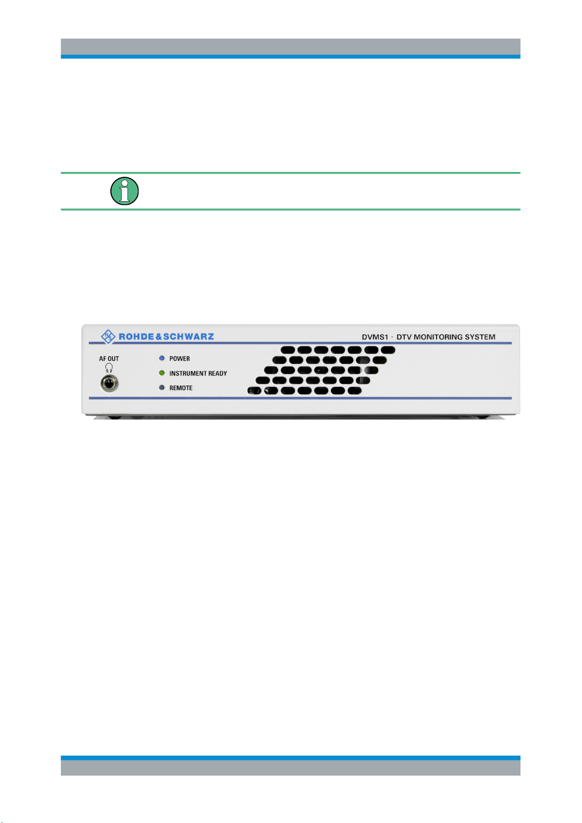
This chapter gives a short overview of the status displays and connectors on the front
panel.
The inscriptions on your R&S DVMS match the captions of the connector descriptions.
Figure 3-1: Front panel view
3.1.1 Status Display LEDs
The basic status is indicated by LEDs.
3.1.1.1 POWER
Displays the power supply status.
●
LED off: No power is supplied. R&S DVMS is switched off.
●
LED blue: Power is supplied.
●
LED red (flashing): Failure of fan.
To rectify this failure, switch the R&S DVMS off and on again. If the fan still does
not work, shut down the R&S DVMS to prevent overheating of the R&S DVMS and
contact one of our customer support centers.
Further information:
●
Chapter 3.2.1, "AC Power Supply Connector", on page 15
13Getting Started 2113.7619.02 ─ 12
Page 20
R&S® DVMS1
3.1.1.2 INSTRUMENT READY
3.1.1.3 REMOTE
Interfaces and Connectors
Rear Panel
Displays the status of the R&S DVMS.
●
LED off: R&S DVMS is not ready for operation.
For example, after powering up until the startup process is completed; the LED status display changes thereafter.
●
LED green: R&S DVMS is ready for operation.
●
LED yellow: R&S DVMS is not ready for operation because the main application,
TS analyzer, is not running (e.g. has been stopped).
Displays the remote control status within the last second.
●
LED off: R&S DVMS is not used for remote control.
●
LED green: R&S DVMS is remote controlled.
●
LED yellow: R&S DVMS is sending SNMP traps.
3.1.2 Connectors
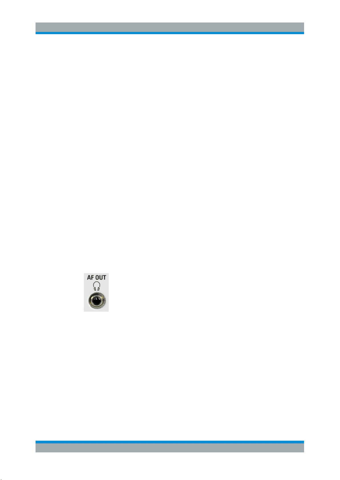
3.1.2.1 AF OUT (Headphones)
The jack socket for the L/R analog audio output provides the decoded audio stream of
the VLC software decoder as a stereo signal.
The socket is intended for connecting headphones or an active loudspeaker.
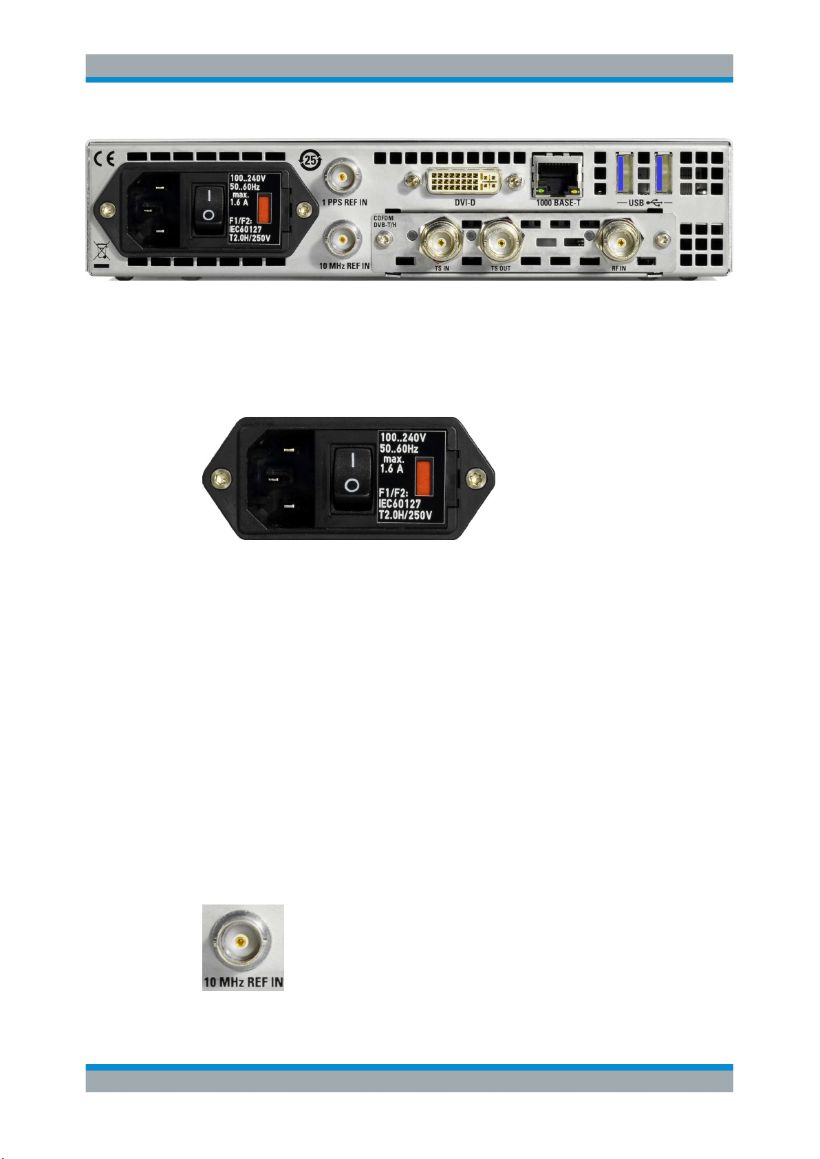
3.2 Rear Panel
This chapter gives a short overview of the connectors on the rear panel.
The option module depends on your choice. In this chapter, all available option modules are described.
14Getting Started 2113.7619.02 ─ 12
Page 21
R&S® DVMS1
3.2.1 AC Power Supply Connector
Interfaces and Connectors
Rear Panel
Figure 3-2: Rear panel view (example)
The AC power supply connector and the AC power switch are combined.
Switch positions:
●
[I]: Depending on the setting of the On/Standby function key on the front panel, the
instrument is either in standby mode or in operation.
●
[O]: The entire instrument is disconnected from the AC power supply.
Further information:
●
Chapter 4.1, "Connecting to the AC Power Supply", on page 26
●
Chapter 5, "Switching On or Off the Instrument", on page 28
●
Chapter 9.2, "Replacing the Fuses", on page 51
3.2.2 10 MHz REF IN
This BNC jack is used as input for the 10 MHz reference frequency. The reference frequency input of the R&S DVMS is used for high accuracy measurements such as RF
frequency offset, TS bit rate or PCR drift/offset. To activate this input, use the "Setup"
menu.
For details, refer to the user manual or help system.
15Getting Started 2113.7619.02 ─ 12
Page 22
R&S® DVMS1
3.2.3 1 PPS REF IN
3.2.4 DVI-D
Interfaces and Connectors
Rear Panel
This BNC jack is used as input for the 1PPS (1 pulse per second) reference pulse. The
1PPS reference pulse input of the R&S DVMS is used for measuring the network delay
in DVB‑T distribution networks. Use a signal derived from an external GPS receiver
that provides short pulses at exactly 1 second distance. This input is activated, if one of
the SFN synchronization monitoring subparameters "SFN Sync Network Delay" is activated.
For details, refer to the user manual or help system.
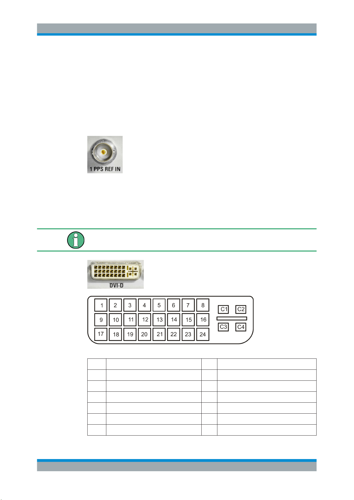
The DVI‑D socket provides the monitor output signal of the built-in computer. Use a
computer monitor that provides a resolution of 1024x768 pixels or higher.
You can use a DVI‑I cable for connecting R&S DVMS and display, but the analog video
interface (pins C1 to C4) is not provided by the R&S DVMS.
Table 3-1: Pin assignment
Pin Signal Pin Signal
1 TMDS data 2- 15 Ground (for +5V)
2 TMDS data 2+ 16 Hot plug detect (HPD)
3 TMDS data 2 shield 17 TMDS data 0-
4 Not used 18 TMDS data 0+
5 Not used 19 TMDS data 0 shield
6 DDC clock 20 Not used
16Getting Started 2113.7619.02 ─ 12
Page 23
R&S® DVMS1
3.2.5 LAN Interface
Interfaces and Connectors
Rear Panel
Pin Signal Pin Signal
7 DDC data 21 Not used
8 Analog vertical sync 22 TMDS clock shield
9 TMDS data 1- 23 TMDS clock+
10 TMDS data 1+ 24 TMDS Clock-
11 TMDS data 1 shield C1 Not used
12 Not used C2 Not used
13 Not used C3 Not used
14 +5V power C4 Not used
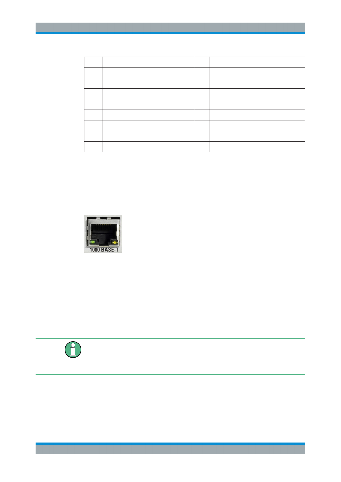
The 1 gigabit LAN interface (1000 Base‑T) can be used to connect the R&S DVMS to a
local network for remote control, printouts and data transfer. The assignment of the
RJ45 connector supports twisted-pair category 7 STP cables in a star configuration
(STP for shielded twisted pair).
Two LEDs indicate the status of the LAN connection.
●
Green LED
– LED off: No connection
– LED on (steady): Connection is established.
– LED blinking: Connection is established, communication line is in a busy state.
●
Yellow LED
– LED off: Connection speed is 10 Mbit/s or 100 Mbit/s.
– LED on (steady): Connection speed is 1000 Mbit/s.
Do not connect or disconnect the network cable until the instrument is switched off.
Otherwise, the network connection cannot be reliably detected.
Electromagnetic interference (EMI) can affect the measurement results. To avoid any
impact, use category 7 cables.
Further information:
●
Chapter 7, "Operating the R&S DVMS in a LAN", on page 38
17Getting Started 2113.7619.02 ─ 12
Page 24
R&S® DVMS1
3.2.6 USB Interfaces
Interfaces and Connectors
Rear Panel
Two USB 3.0 interfaces of the type A (host USB) are provided (USB = universal serial
bus). Use the interfaces to connect external devices like a keyboard, mouse, printer, or
memory stick.
On demand, a USB 3.0 interface supplies up to 900 mA.
Further information:
●
Chapter 4.2, "Connecting External Devices", on page 26
Electromagnetic interference (EMI) can affect the measurement results. To avoid any
impact, make sure that the following conditions are met:
●
Use suitable double-shielded cables.
●
Do not use USB connecting cables exceeding 1 m.
●
Use only USB devices that remain within the permissible EMI limits.
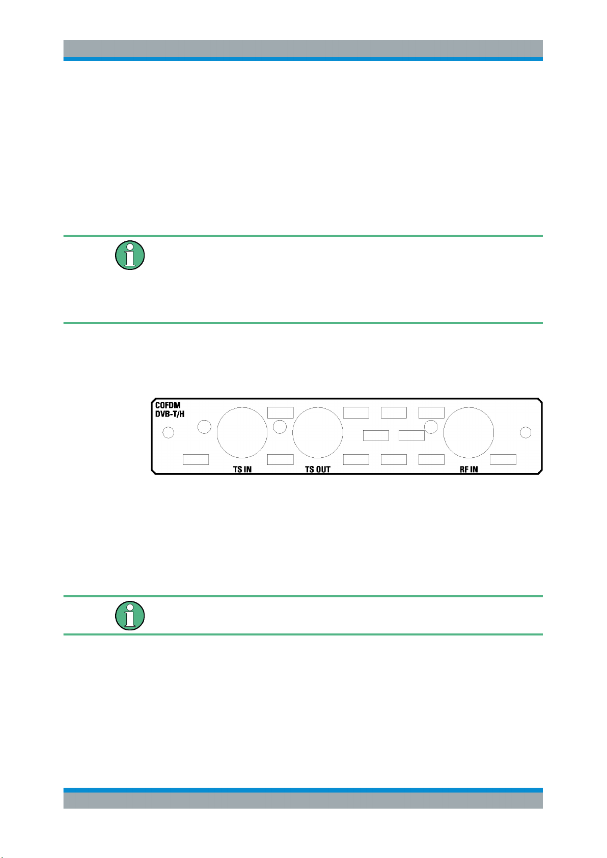
3.2.7 DVB-T/H Receiver Module (R&S DVMS-B53)
The DVB‑T/H receiver module (R&S DVMS‑B53) is an option module.
Figure 3-3: DVB-T/H receiver module
The status of the connectors is indicated by LEDs. Before showing a new state, each
LED holds the current state for at least one second, if the current state is not "off" or
"flashing".
To select the input, in the toolbar, click "Instrument Configuration" and then select "Signal Interface". See the user manual or help system.
To help locating a connector socket, you can let its status LED flash blue ("Instrument
Configuration" dialog, "Signal Interfaces" tab, see the user manual or help system).
RF IN
This BNC socket (female connector @DVMS) is used to feed in an RF signal conforming to the DVB‑T (EN 300 744) or DVB‑H (EN 302 304) standards.
An LED indicates the RF IN status:
●
LED off: Input is not used for monitoring.
18Getting Started 2113.7619.02 ─ 12
Page 25
R&S® DVMS1
Interfaces and Connectors
Rear Panel
●
LED green: Input is used for monitoring. Synchronization state is valid for both RF
signal and related transport stream.
●
LED yellow: Input is used for monitoring but synchronization cannot be achieved.
TS IN
This BNC socket is used to feed in an MPEG2 transport stream signal conforming to
the DVB‑ASI (EN 50083‑9 (2002)) or SMPTE (SMPTE 310M) interface standards.
An LED indicates the TS IN status:
●
LED off: Input is not used for monitoring.
●
LED green: Input is used for monitoring. Synchronization state is valid for the transport stream signal.
●
LED yellow: Input is used for monitoring but synchronization cannot be achieved.
TS OUT
This BNC socket provides an MPEG2 transport stream signal conforming to the
DVB‑ASI (EN 50083‑9 (2002)) interface standard.
The interface is used as a loop output for a transport stream signal from the [RF In] or
[TS In] input (see above).
An LED indicates the TS OUT status:
●
LED off: Output is not used.
●
LED blue: Output is used as loop output.
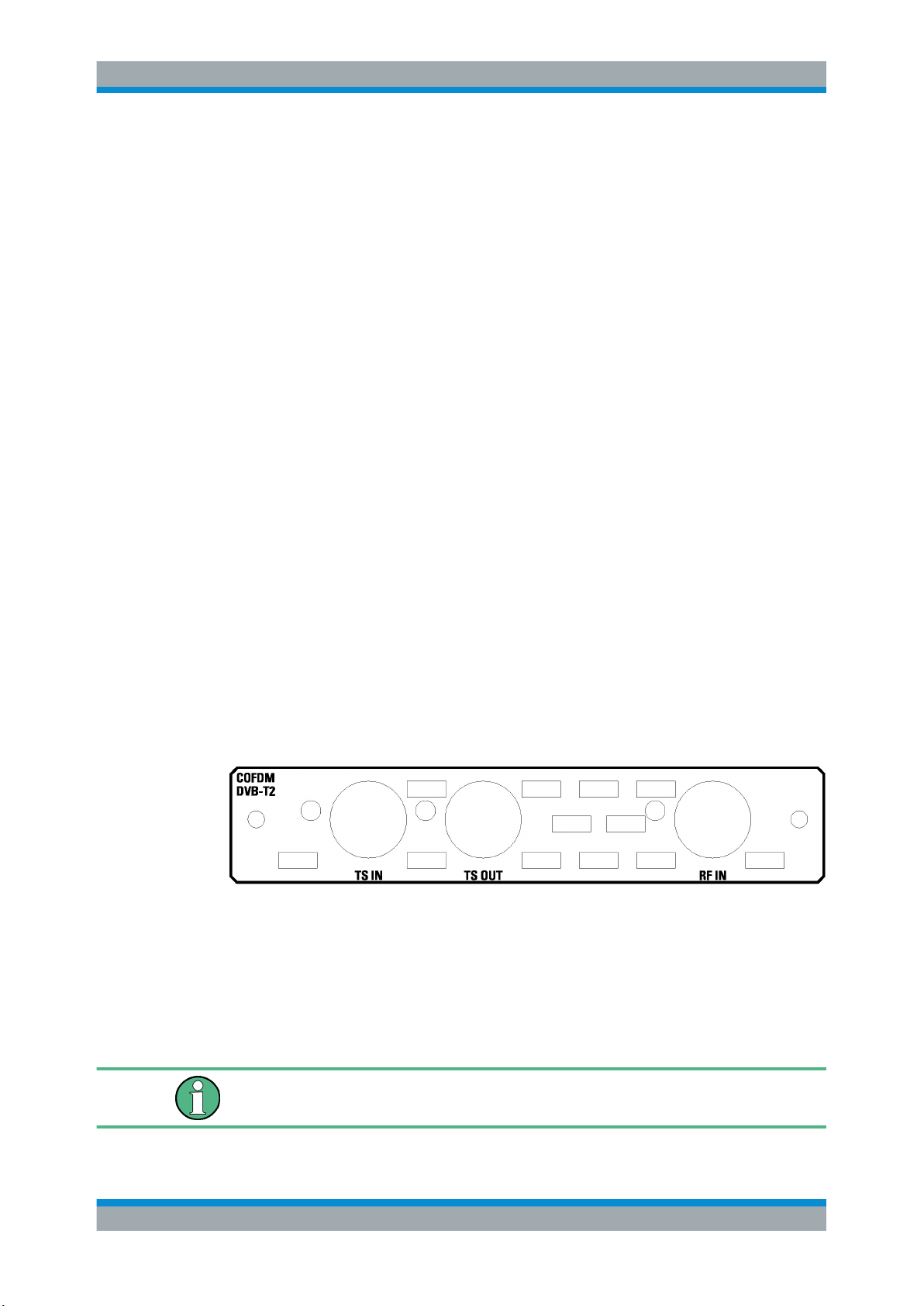
3.2.8 DVB-T/DVB-T2 Receiver Module (R&S DVMS-B55)
The T/T2 receiver module (R&S DVMS‑B55) is an option module.
Figure 3-4: DVB-T/T2 receiver module
The status of the connectors is indicated by LEDs. Before showing a new state, each
LED holds the current state for at least one second, if the current state is not "off" or
"flashing".
To select the input, in the toolbar, click "Instrument Configuration" and then select "Signal Interface". See the user manual or help system.
To help locating a connector socket, you can let its status LED flash blue ("Instrument
Configuration" dialog, "Signal Interfaces" tab, see the user manual or help system).
19Getting Started 2113.7619.02 ─ 12
Page 26
R&S® DVMS1
Interfaces and Connectors
Rear Panel
RF IN
This BNC socket (female connector @DVMS) is used to feed in an RF signal conforming to the DVB‑T2 (ETSI EN 302 755) standard.
An LED indicates the RF IN status:
●
LED off: Input is not used for monitoring.
●
LED green: Input is used for monitoring. Synchronization state is valid for both RF
signal and related transport stream.
●
LED yellow: Input is used for monitoring but synchronization cannot be achieved.
TS IN
This BNC socket is used to feed in an MPEG2 transport stream signal conforming to
the DVB‑ASI (EN 50083‑9 (2002)) or SMPTE (SMPTE 310M) interface standards.
An LED indicates the TS IN status:
●
LED off: Input is not used for monitoring.
●
LED green: Input is used for monitoring. Synchronization state is valid for the transport stream signal.
●
LED yellow: Input is used for monitoring but synchronization cannot be achieved.
TS OUT
This BNC socket provides an MPEG2 transport stream signal conforming to the
DVB‑ASI (EN 50083‑9 (2002)) interface standard.
The interface is used as a loop output for a transport stream signal from the [RF In] or
[TS In] input (see above).
An LED indicates the TS OUT status:
●
LED off: Output is not used.
●
LED blue: Output is used as loop output.
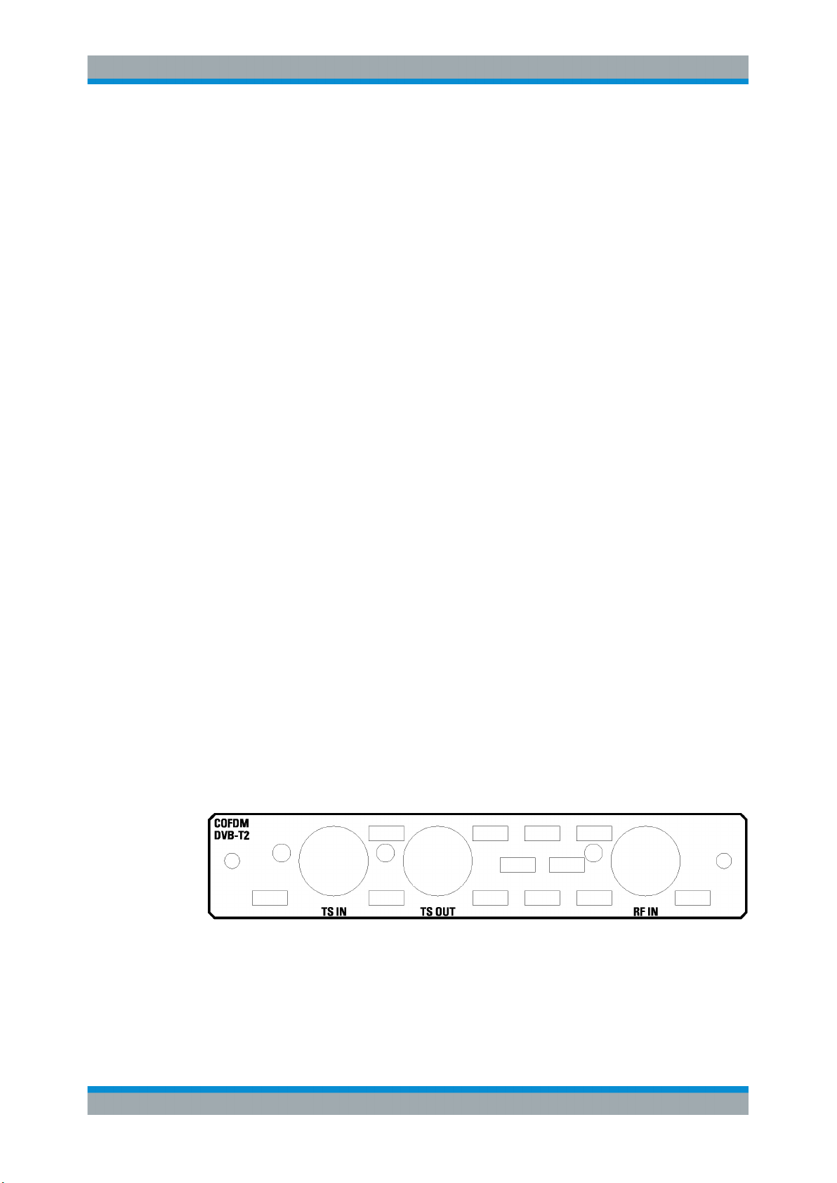
3.2.9 DVB-T2 Receiver Module (R&S DVMS-B54)
The T2 receiver module (R&S DVMS‑B54) is an option module.
Figure 3-5: DVB-T2 receiver module
The status of the connectors is indicated by LEDs. Before showing a new state, each
LED holds the current state for at least one second, if the current state is not "off" or
"flashing".
20Getting Started 2113.7619.02 ─ 12
Page 27
R&S® DVMS1
Interfaces and Connectors
Rear Panel
To select the input, in the toolbar, click "Instrument Configuration" and then select "Signal Interface". See the user manual or help system.
To help locating a connector socket, you can let its status LED flash blue ("Instrument
Configuration" dialog, "Signal Interfaces" tab, see the user manual or help system).
RF IN
This BNC socket (female connector @DVMS) is used to feed in an RF signal conforming to the DVB‑T2 (ETSI EN 302 755) standard.
An LED indicates the RF IN status:
●
LED off: Input is not used for monitoring.
●
LED green: Input is used for monitoring. Synchronization state is valid for both RF
signal and related transport stream.
●
LED yellow: Input is used for monitoring but synchronization cannot be achieved.
TS IN
This BNC socket is used to feed in an MPEG2 transport stream signal conforming to
the DVB‑ASI (EN 50083‑9 (2002)) or SMPTE (SMPTE 310M) interface standards.
An LED indicates the TS IN status:
●
LED off: Input is not used for monitoring.
●
LED green: Input is used for monitoring. Synchronization state is valid for the transport stream signal.
●
LED yellow: Input is used for monitoring but synchronization cannot be achieved.
TS OUT
This BNC socket provides an MPEG2 transport stream signal conforming to the
DVB‑ASI (EN 50083‑9 (2002)) interface standard.
The interface is used as a loop output for a transport stream signal from the [RF In] or
[TS In] input (see above).
An LED indicates the TS OUT status:
●
LED off: Output is not used.
●
LED blue: Output is used as loop output.
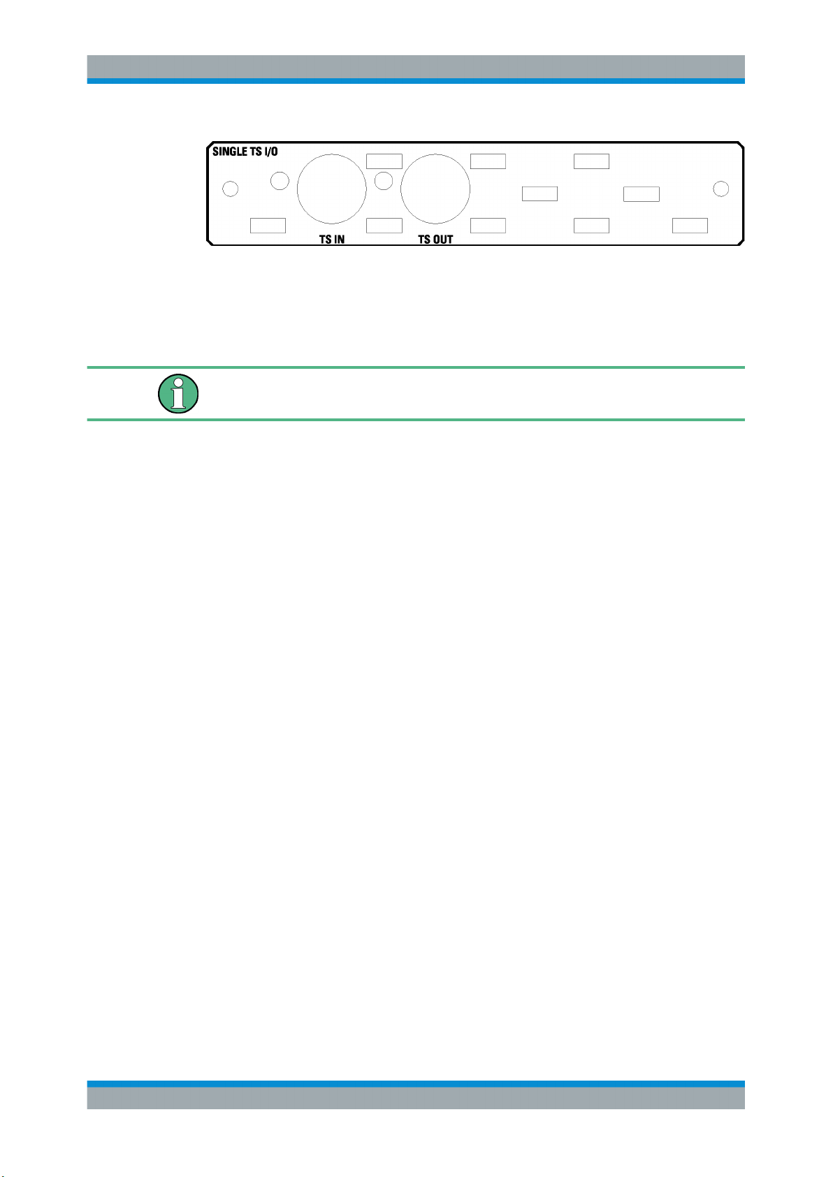
3.2.10 Single TS Input Module (R&S DVMS-B11)
The single TS input module (R&S DVMS‑B11) is an option module.
21Getting Started 2113.7619.02 ─ 12
Page 28
R&S® DVMS1
Interfaces and Connectors
Rear Panel
Figure 3-6: Single TS input module
The status of the connectors is indicated by LEDs. Before showing a new state, each
LED holds the current state for at least one second, if the current state is not "off" or
"flashing".
To help locating a connector socket, you can let its status LED flash blue ("Instrument
Configuration" dialog, "Signal Interfaces" tab, see the user manual or help system).
TS IN
This BNC socket is used to feed in an MPEG2 transport stream signal conforming to
the DVB‑ASI (EN 50083‑9 (2002)) or SMPTE (SMPTE 310M) interface standards.
An LED indicates the TS IN status:
●
LED off: Input is not used for monitoring.
●
LED green: Input is used for monitoring. Synchronization state is valid for the transport stream signal.
●
LED yellow: Input is used for monitoring but synchronization cannot be achieved.
TS OUT
This BNC socket provides an MPEG2 transport stream signal conforming to the
DVB‑ASI (EN 50083‑9 (2002)) interface standard. The interface is used as a loop output for a transport stream signal from the [TS In] input (see above).
To select the input, in the toolbar, click "Instrument Configuration" and then select "Signal Interface". See the user manual or help system.
An LED indicates the TS OUT status:
●
LED off: Output is not used.
●
LED blue: Output is used as loop output.
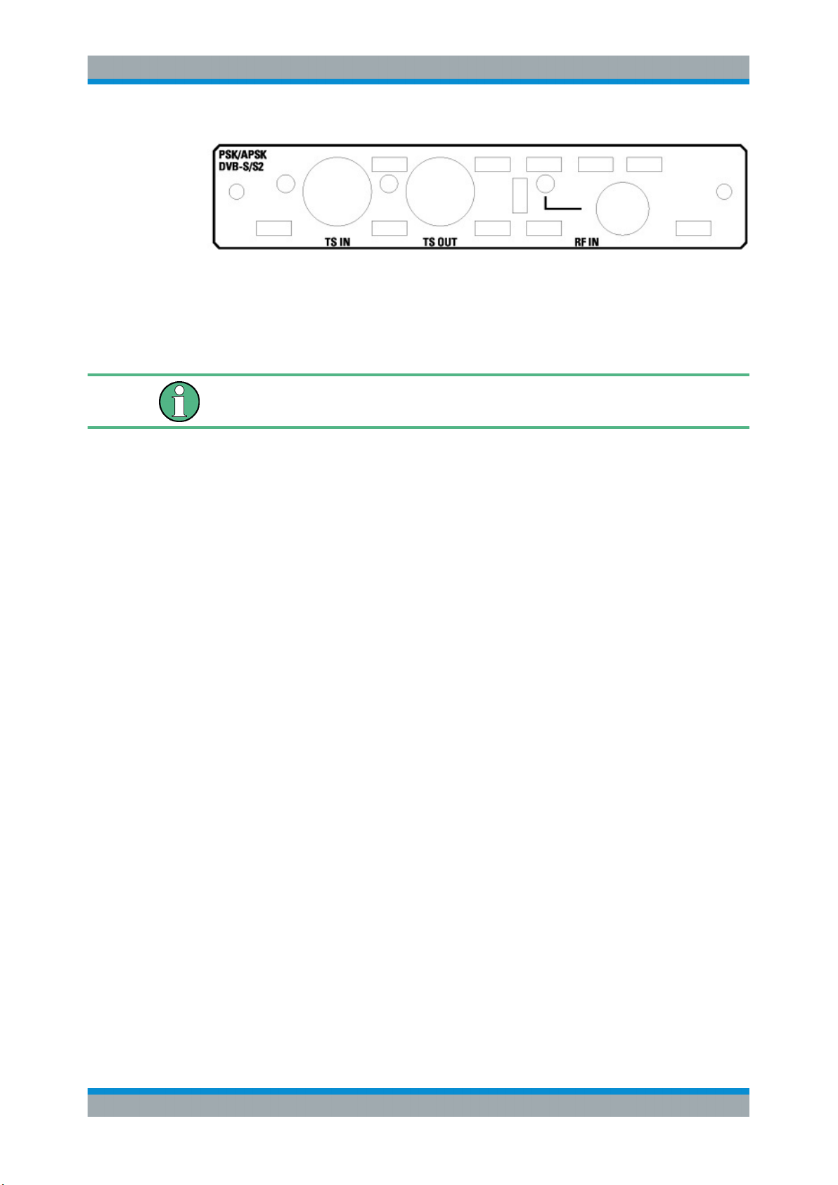
3.2.11 S/S2 Receiver Module (R&S DVMS-B51)
The S/S2 receiver module (R&S DVMS‑B51) is an option module.
22Getting Started 2113.7619.02 ─ 12
Page 29
R&S® DVMS1
Interfaces and Connectors
Rear Panel
Figure 3-7: S/S2 receiver module
The status of the connectors is indicated by LEDs. Before showing a new state, each
LED holds the current state for at least one second, if the current state is not "off" or
"flashing".
To help locating a connector socket, you can let its status LED flash blue ("Instrument
Configuration" dialog, "Signal Interfaces" tab, see the user manual or help system).
RF IN
This F socket (female connector @DVMS) is used to feed in an RF signal conforming
to the DVB‑S (EN 300421), DVB‑S2 (EN 302307) or DIRECTV legacy modulation
standards.
An LED indicates the RF IN status:
●
LED off: Input is not used for monitoring.
●
LED green: Input is used for monitoring. Synchronization state is valid for both RF
signal and related transport stream.
●
LED yellow: Input is used for monitoring but synchronization cannot be achieved.
TS IN
This BNC socket is used to feed in an MPEG2 transport stream signal conforming to
the DVB‑ASI (EN 50083‑9 (2002)) or SMPTE (SMPTE 310M) interface standards.
An LED indicates the TS IN status:
●
LED off: Input is not used for monitoring.
●
LED green: Input is used for monitoring. Synchronization state is valid for the transport stream signal.
●
LED yellow: Input is used for monitoring but synchronization cannot be achieved.
TS OUT
This BNC socket provides an MPEG2 transport stream signal conforming to the
DVB‑ASI (EN 50083‑9 (2002)) interface standard.
The interface is used as a loop output for a transport stream signal from the [RF In] or
[TS In] input (see above).
To select the input, in the toolbar, click "Instrument Configuration" and then select "Signal Interface". See the user manual or help system.
23Getting Started 2113.7619.02 ─ 12
Page 30
R&S® DVMS1
3.2.12 TS/IP Interface Module (R&S DVMS-B40)
An LED indicates the TS OUT status:
●
LED off: Output is not used.
●
LED blue: Output is used as loop output.
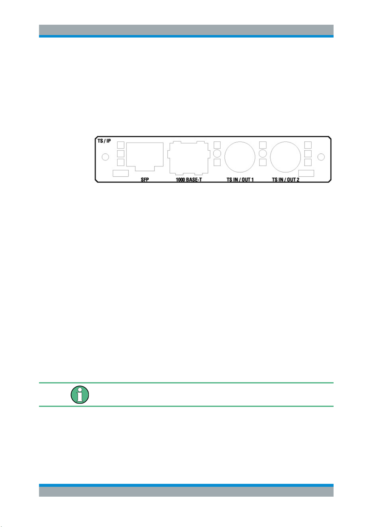
The TS/IP module (R&S DVMS‑B40) is an option module.
Figure 3-8: TS/IP interface module
Interfaces and Connectors
Rear Panel
TS IN/OUT 1 and TS IN/OUT 2
Each of these two BNC sockets is used either as input or output for MPEG2 transport
streams. If used as an input, feed in an MPEG2 transport stream signal conforming to
the DVB‑ASI (EN 50083‑9 (2002)) or SMPTE (SMPTE310M) interface standards. If
used as an output, this socket provides an MPEG2 transport stream signal conforming
to the DVB‑ASI (EN 50083‑9 (2002)) interface standard. The output can be used as a
loop output for any transport stream input signal available.
To select the input or output, in the toolbar, click "Instrument Configuration" and then
select "Signal Interface". See the user manual or help system.
The status of the connectors is indicated by LEDs. Before showing a new status, each
LED holds the status for at least one second, if the status is not "off" or "flashing".
●
LED off: Connector is not used.
●
LED blue: Connector is used as a loop output for any MPEG2 transport stream
input signal.
●
LED green: Connector is used as an input for monitoring. Synchronization state is
valid for the transport stream signal.
●
LED yellow: Connector is used as an input for monitoring but synchronization cannot be achieved.
To help locating a connector socket, you can let its status LED flash ("Instrument Configuration" dialog, "Signal Interfaces" tab, see the user manual or help system).
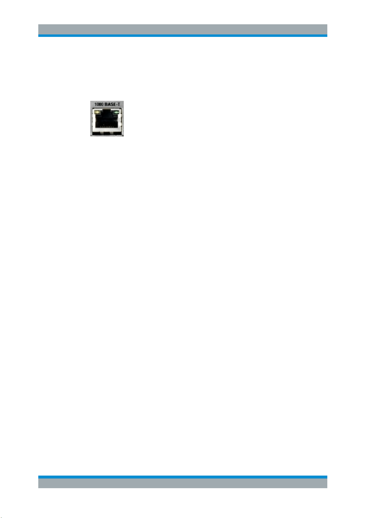
1000 BASE-T
This 1000 Base‑T gigabit interface socket is used either as:
●
Input for IP and TS monitoring (IP in flow)
●
IP loop output (IP out flow) for encapsulated MPEG2 transport streams conforming
to the Pro-MPEG code of practice #3 (release 2)
24Getting Started 2113.7619.02 ─ 12
Page 31
R&S® DVMS1
Interfaces and Connectors
Rear Panel
To select and configure the IP in flows and IP out flows, in the toolbar, click "Instrument
Configuration" and then select "Signal Interface". See the user manual or help system.
The assignment of the RJ45 connector supports twisted-pair category 7 STP cables in
a star configuration (STP for shielded twisted pair).
Two LEDs indicate the status of the LAN connection.
●
Yellow LED (left)
– LED off: Connection speed is 10 Mbit/s or 100 Mbit/s.
– LED on (steady): Connection speed is 1000 Mbit/s.
●
Green LED (right)
– LED off: No connection
– LED on (steady): Connection is established.
– LED blinking: Connection is established, communication line is in a busy state.
SFP
This SFP (small formfactor plugable) module socket is used to connect an additional IP
interface by insertion of an optical gigabit SFP module (1000BASE‑X). If inserted, the
additional SFP IP connector is used and configured in the same manner as the built-in
1000 BASE‑T connector (see "1000 BASE-T" on page 24).
The SFP module is not part of the R&S DVMS‑B40 option.
25Getting Started 2113.7619.02 ─ 12
Page 32
R&S® DVMS1
4.1 Connecting to the AC Power Supply
Connecting the Instrument
Connecting External Devices
4 Connecting the Instrument
This chapter describes how to connect the instrument to the power supply and external
devices.
Preventing electromagnetic interference
Use only suitable and double-shielded signal/control cables with at least 80 dB to
1 GHz shielding.
In particular cables that are connected to the ASI inputs and outputs can cause
EMC problems. Depending on the data rate and the packet timing of the transport
stream, high levels can occur sporadically within the signal spectrum.
The R&S DVMS can be used with different AC power voltages and adapts itself automatically to it. Adjusting the instrument to a particular AC supply voltage is therefore
not required. See the data sheet for the requirements of voltage and frequency.
Shock hazard
Observe the basic safety instructions at the beginning of this manual, especially the
instructions on electrical safety.
1. If you use the S/S2 receiver module (R&S DVMS‑B51), connect this module before
switching on the R&S DVMS (see Chapter 3.2.11, "S/S2 Receiver Module
(R&S DVMS-B51)", on page 22).
2. Connect the R&S DVMS to the AC power supply, using the supplied power cable.
The AC power connector is on the rear panel of the instrument.
Since the R&S DVMS complies with safety class EN61010‑1, connect it only to a
socket with a ground contact.
4.2 Connecting External Devices
Using the USB interfaces, you can directly connect USB devices to the R&S DVMS.
This number can be increased as necessary by using USB hubs.
Due to the large number of available USB devices, there is almost no limit to the possible expansions. In the following, USB devices that can be useful are listed:
●
Keyboard for entering comments, filenames, etc.
●
Mouse for easy operation of Windows dialogs
26Getting Started 2113.7619.02 ─ 12
Page 33
R&S® DVMS1
Connecting the Instrument
Connecting External Devices
●
Memory stick for easy transfer of data to/from a computer (e.g. firmware updates)
●
CD–ROM drives for installing software
●
Printer for printing measurement results
To install a USB device
1. Connect the USB device to the R&S DVMS at any time. All USB devices are
Plug & Play.
Windows 7 automatically searches for a suitable device driver.
2. If Windows 7 does not find a suitable driver, it prompts you to specify a directory
that contains the driver software. If the driver software is on a CD‑ROM, connect a
USB CD–ROM drive to the R&S DVMS before proceeding.
Before connecting an external device that is not a USB device, e.g. a monitor, make
sure that the R&S DVMS is switched off. Otherwise, correct operation cannot be
assured.
To uninstall a USB device
► Disconnect the USB device from the R&S DVMS at any time.
Windows 7 immediately detects the change in the hardware configuration and
deactivates the corresponding driver.
27Getting Started 2113.7619.02 ─ 12
Page 34
R&S® DVMS1
5.1 Switching On the Instrument
Switching On or Off the Instrument
Switching On the Instrument
5 Switching On or Off the Instrument
Shock hazard
Observe the basic safety instructions at the beginning of this manual, especially the
instructions on electrical safety.
Risk of instrument damage
Before switching on the instrument, make sure that the following conditions are met:
●
The instrument is set up as described in Chapter 2.2, "Putting Up the Instrument",
on page 11.
●
Signal levels at the input connectors are all within the specified ranges.
●
Signal outputs are correctly connected and are not overloaded.
Failure to meet these conditions can damage the instrument or other devices in the
test setup.
To switch on the R&S DVMS
1. Make sure to connect the R&S DVMS to a power supply (for details see Chap-
ter 4.1, "Connecting to the AC Power Supply", on page 26).
2. Press the AC power switch on the rear panel into [I] position.
The LED under [POWER] changes to blue.
The R&S DVMS starts booting. After booting is completed, the R&S DVMS is ready
for operation.
The LED under [INSTRUMENT READY] changes to yellow and then to green.
The configuration settings that were active before the R&S DVMS was last
switched off are automatically restored.
28Getting Started 2113.7619.02 ─ 12
Page 35
R&S® DVMS1
5.2 Switching Off the Instrument
Switching On or Off the Instrument
Checking the Provided Software Options
Risk of losing data
If you switch off the running instrument using the rear panel switch or by disconnecting
the power cord before shutting it down, the instrument loses its current settings. Furthermore, program data can be lost.
Always shut down the R&S DVMS first.
To switch off the R&S DVMS
1. Check the status displays on the front panel of the R&S DVMS. If the [REMOTE]
status display on the front panel is on, do not switch off the R&S DVMS. Someone
else is using the R&S DVMS by remote operation (see also Chapter 3.1.1, "Status
Display LEDs", on page 13).
2. Shut down the R&S DVMS.
The R&S DVMS stores the current configuration settings automatically.
On the front panel, the LED under [INSTRUMENT READY] changes from green to
yellow.
3. Set the AC switch on the rear panel to the [O] position, or disconnect the
R&S DVMS from the AC power supply.
All LEDs on the front panel go out.
5.3 Checking the Provided Software Options
The R&S DVMS can be equipped with software options. To check whether the installed
options correspond to the options indicated on the delivery note, proceed as follows.
1. In the "Help" menu, select "Option Management".
A list with the software options is displayed.
2. Check the options enabled via license keys as indicated in the delivery note.
For an overview of the all options available for the R&S DVMS, see the Rohde &
Schwarz homepage (www.rohde-schwarz.com/product/dvms).
29Getting Started 2113.7619.02 ─ 12
Page 36

R&S® DVMS1
Sample Application
6 Sample Application
Follow the instructions in this chapter to perform your first measurement with the
R&S DVMS.
For an expanded selection of measurement examples and background information,
refer to the user manual or the help system.
In this measurement, the R&S DVMS is used for basic compliance checks of one single MPEG2 transport stream (TS) signal.
Since each R&S DVMS option module provides at least one baseband transport
stream input (TS IN), you can perform the described measurement with every
R&S DVMS independently of the option module type.
6.1 Requirements
The DVB TS‑ASI input signal used in this measurement is generated by either a TS
generator (i.e. R&S DVSG) or by any other DVB-compliant TS‑ASI source.
Setting Up the R&S
DVMS
The R&S DVMS is locally operated by using an LCD monitor (DVI input required, at
least 1024 x 768 pixels) and a USB mouse.
6.2 Setting Up the R&S DVMS
The required connectors are on the rear panel of the R&S DVMS. For details on the
connectors, see Chapter 3, "Interfaces and Connectors", on page 13.
1. Connect the TS ASI output of the TS generator to the TS IN baseband input (BNC
connector) of the R&S DVMS option module.
2. Connect the LCD monitor to the DVI‑D monitor output of the R&S DVMS.
3. Plug the USB connector of the USB mouse in one of the two USB interfaces.
4. Switch on the R&S DVMS and wait until the TS analyzer monitoring application is
running.
(Green LED [INSTRUMENT READY] at the front panel of R&S DVMS)
The application window showing the default start screen is displayed.
30Getting Started 2113.7619.02 ─ 12
Page 37
R&S® DVMS1
6.3 Creating a Basic Configuration
Sample Application
Checking the TS Synchronization
In the TS analyzer monitoring application, create the basic configuration.
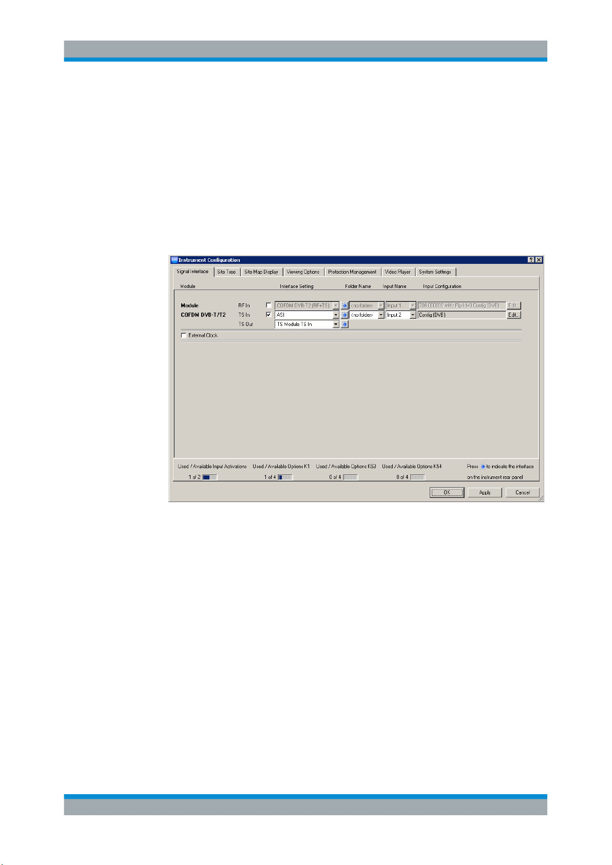
1. In the toolbar, select "Instrument Configuration" to open the "Instrument Configuration" dialog.
2. On the "Signal Interface" tab, select the following:
a) In the "Interface Settings" column, activate the "TS In" option.
b) Deactivate all other input options.
3. Click "OK".
4. In the toolbar, select "Input Configuration" to open the "Input Configuration Assignment" dialog.
5. Under "Monitoring Configuration", select "Config (DVB)".
6.4 Checking the TS Synchronization
Before any measurement can be performed, the TS synchronization within the
R&S DVMS TS analyzer must achieve the "Locked" state. To check the current state,
perform the following steps.
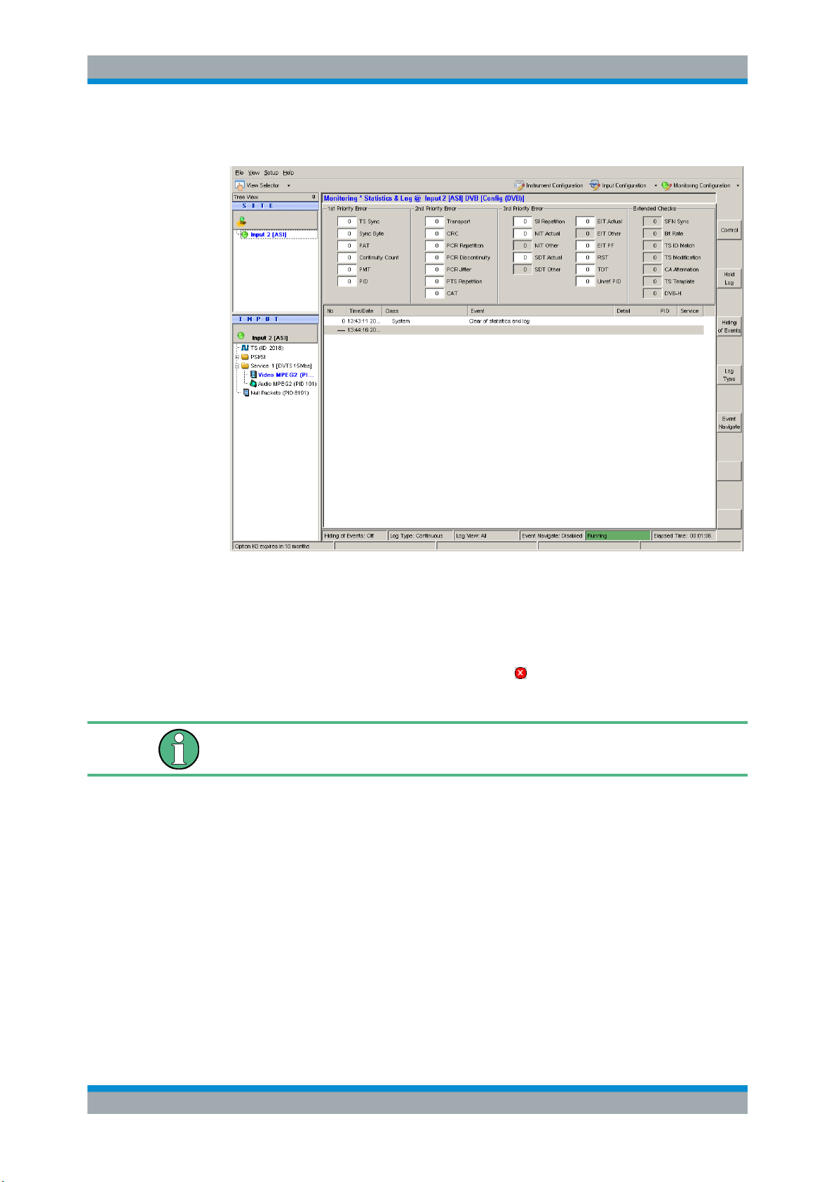
1. In the toolbar, click "View Selector".
2. In the "View Selector" dialog, click the icon for the statistics & log measurement.
3. Click "Control" and select "Clear Statistics & Log".
31Getting Started 2113.7619.02 ─ 12
Page 38
R&S® DVMS1
Sample Application
Performing the Measurement
4. Under "1st Priority Error", check the "TS Sync" statistics counter.
● In the "Locked" state, the value is "0".
Under "SITE", the LED symbol is green. At the rear panel, the LED corresponding to the TS IN input switches to green.
● In the "Unlocked" state, the value is > 0, continuously incrementing (every sec-
ond).
Under "SITE", the LED symbol shows the
panel, the LED corresponding to the TS IN input switches to yellow.
The following measurements can only be performed, if TS synchronization is in the
"Locked" state.
icon for TS synch loss. At the rear
6.5 Performing the Measurement
Since the measurement results strongly depend on the content of the TS input signal,
the following examples use basic parameters and measurements valid for all kind of
MPEG2 TS signals.
6.5.1 Checking the Gross Bit Rate of the Connected TS
1. In the toolbar, click "View Selector".
32Getting Started 2113.7619.02 ─ 12
Page 39
R&S® DVMS1
Sample Application
Performing the Measurement
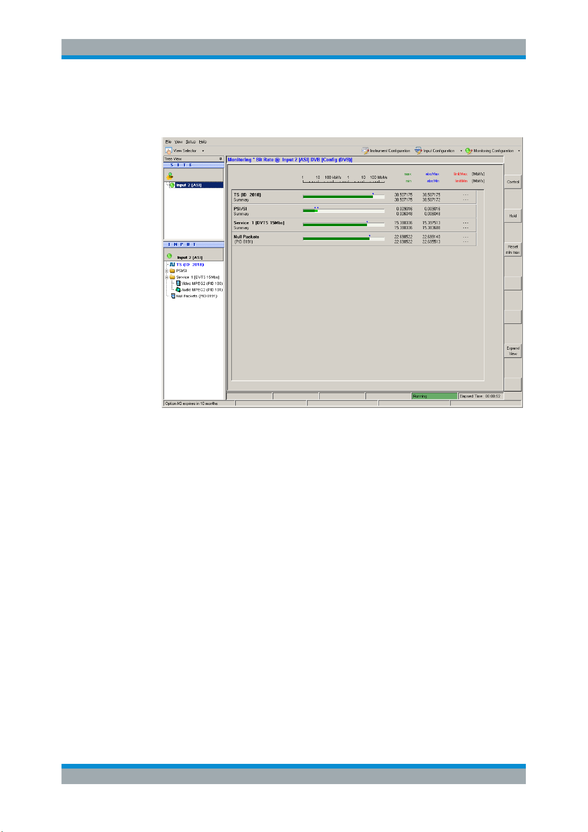
2. In the "View Selector" dialog, click the icon for the bit rate measurement.
3. Read the current bit rate of the connected TS from the TS elements table.
The value is given in units of megabits per second (Mbit/s). The value shown is the
gross value of all transport stream packets per second, including TS packet header
and TS packet payload.
6.5.2 Checking the Net Bit Rate of the Connected TS
To check the net bit rate value of the TS, you have to change the calculation method
for the TS bit rate measurement from gross to net values.
1. In the toolbar, select "Monitoring Configuration".
2. Select the "Extended Checks I" tab.
On this tab, you can see all settings for bit rate measurements.
33Getting Started 2113.7619.02 ─ 12
Page 40
R&S® DVMS1
Sample Application
Performing the Measurement
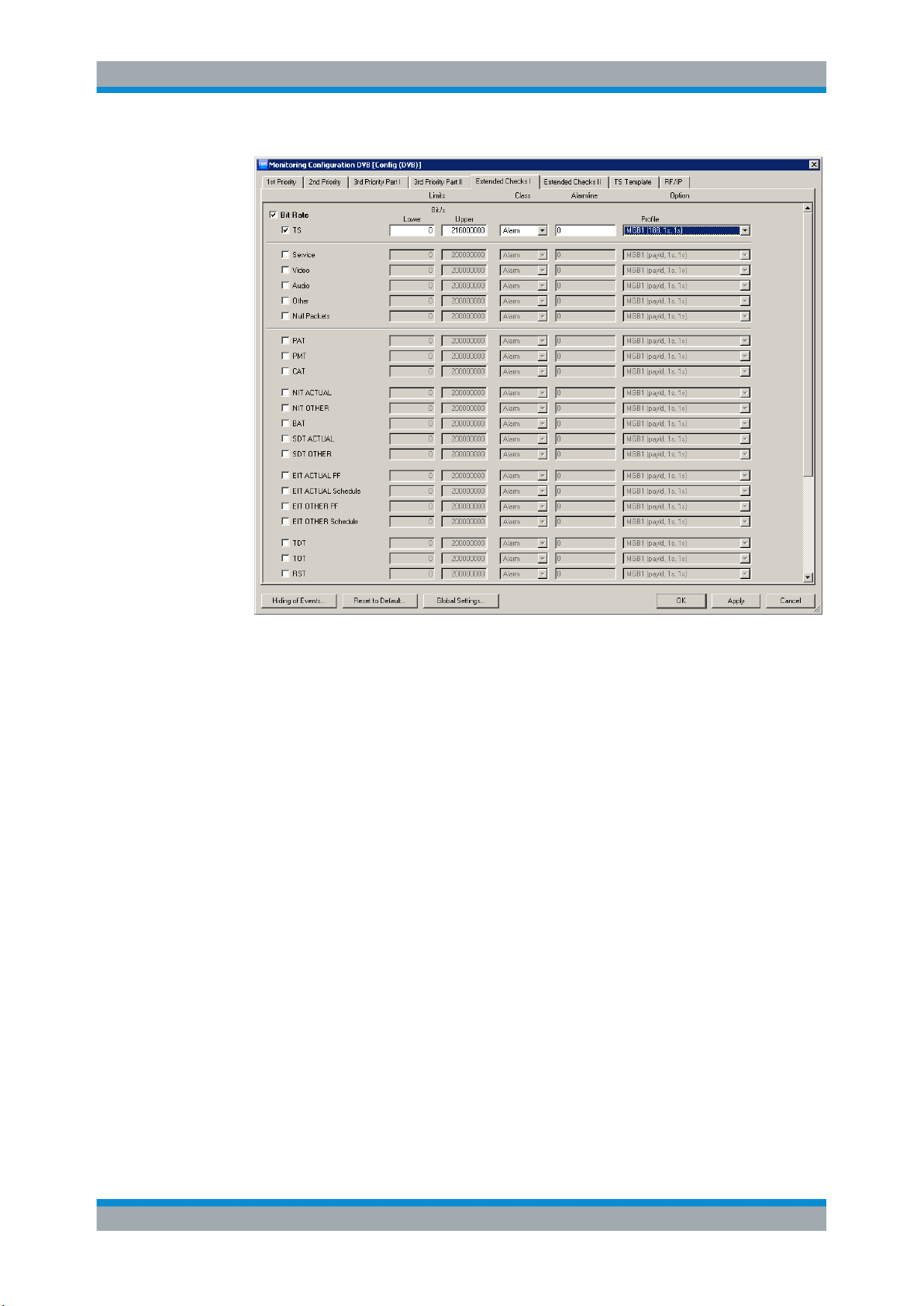
Figure 6-1: Extended Checks I tab
3. In the first line, activate the "Bit Rate" option for overall bit rate limits monitoring.
4. The second line shows the current (default) settings for the monitoring TS bit rate.
To modify the calculation method, do the following:
a) Activate the "TS" option.
b) Open the "Profile" list and select the "MGB1(payld,1,1)" predefined setting.
5. Click "OK" to close the configuration dialog.
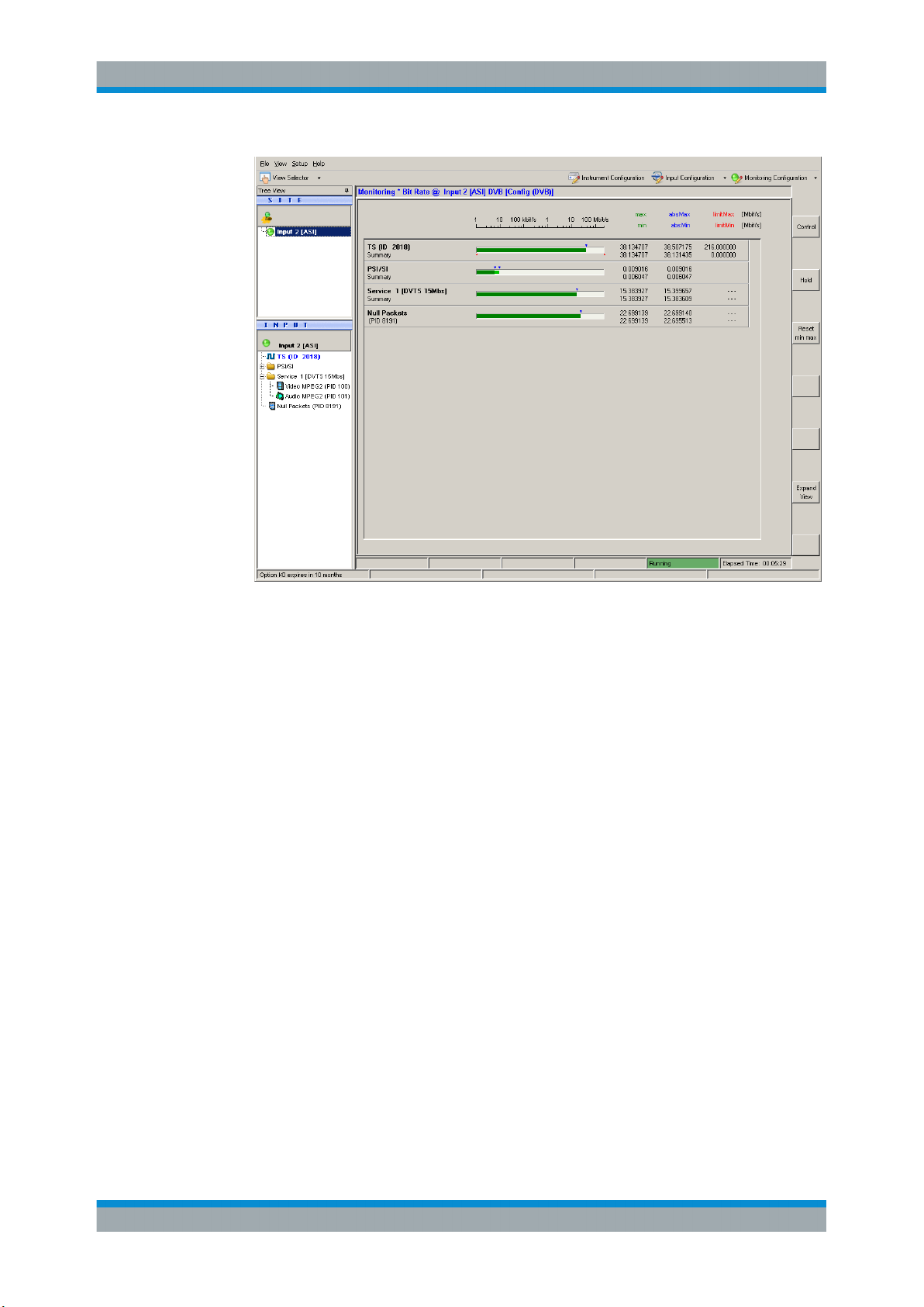
The monitoring view is displayed.
6. In the "TS (ID XXXX)" line, "max/min" column, read the current net bit rate of the
connected TS (in this example, Figure 6-2, XXXX = 2018).
34Getting Started 2113.7619.02 ─ 12
Page 41
R&S® DVMS1
Sample Application
Performing the Measurement
Figure 6-2: Monitoring view
7. Compare this value to the gross value from before (see Chapter 6.5.1, "Checking
the Gross Bit Rate of the Connected TS", on page 32).
Since only the packet payload of all TS packets is examined for net bit rate calculation, the net value should be lower by a factor of approximately 184/188.
6.5.3 Activating the Monitoring Error for TS Bit Rate Monitoring
Now you activate monitoring errors by changing the monitoring limit of the parameter
TS bit rate.
1. In the toolbar, select "Monitoring Configuration".
2. Select the "Extended Checks I" tab (see Figure 6-1).
In the second line, in the "Upper Bit Rate" field, set the limit to a value of approx.
1 Mbit/s below the current TS bit rate as checked in Chapter 6.5.2, "Checking the
Net Bit Rate of the Connected TS", on page 33.
3. Click "OK" to close the configuration dialog.
4. In the toolbar, click "View Selector".
5. In the "View Selector" dialog, click the icon for the statistics & log measurement.
6. Click "Control" and select "Clear Statistics & Log".
7. Check the monitoring log.
35Getting Started 2113.7619.02 ─ 12
Page 42
R&S® DVMS1
Sample Application
Performing the Measurement
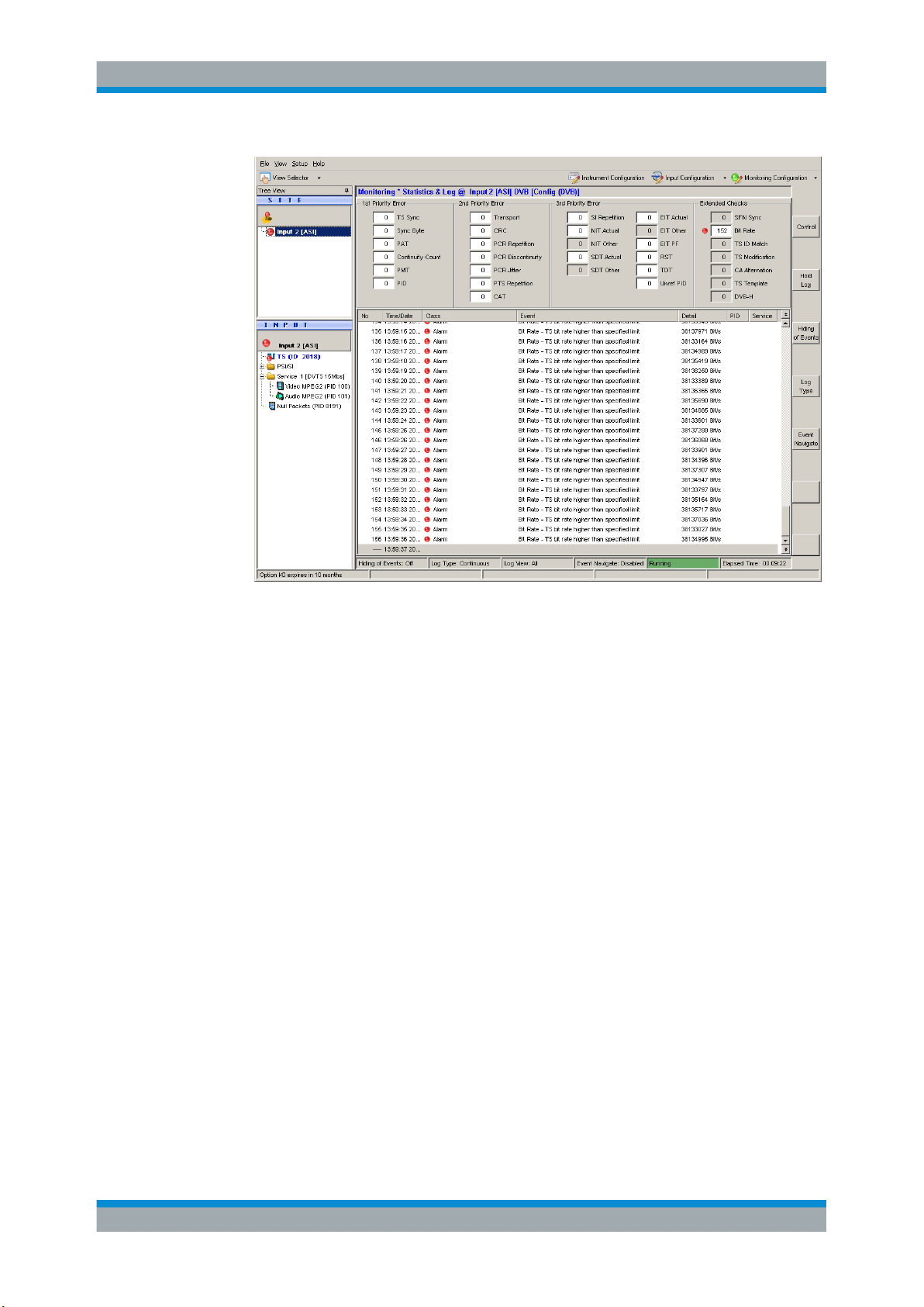
Every second, "Bite Rate - TS bit rate higher than specified limit" log entries are
inserted at the end of the log. In addition, the "Bit Rate" statistics counter is incremented every second. Also, under "INPUT", a red LED symbol at the selected
input indicates an active monitoring fault.
8. To simplify the monitoring log, click "Log Type" and then select "Transition" to
change the log type.
Only at the moment when the monitoring error is detected, one single entry is
inserted. As long as the error is present, no new log entries are added, but the
"Statistics Counter" is incremented. When the monitoring error disappears, a new
log entry is inserted informing you that the error has disappeared and how long the
error has lasted.
For further details, see the user manual or help system.
9. Stop reporting the monitoring faults by deactivating the TS bit rate monitoring:
a) In the toolbar, select "Monitoring Configuration".
b) Select the "Extended Checks I" tab.
c) In the second line, deactivate the "TS" option for TS bit rate monitoring.
10. Click "OK" to close the configuration dialog.
11. Click "Control" and select "Clear Statistics & Log".
6.5.4 Checking the Content of the PSI Table PAT
PAT is used as abbreviation for program association table as specified in the associated MPEG2 standard ISO/IEC13818‑1.
36Getting Started 2113.7619.02 ─ 12
Page 43
R&S® DVMS1
Sample Application
Performing the Measurement
1. In the toolbar, click "View Selector".
2. In the "View Selector" dialog, click the icon for the Table/PES/T2‑MI interpreter.
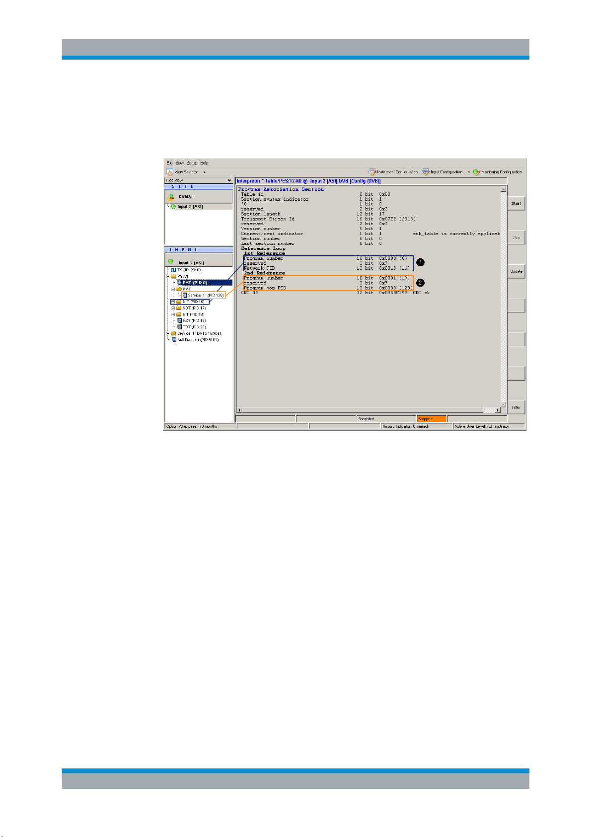
3. Under "INPUT", expand the PSI/SI node and select the PAT element.
1 = Network PID (NIT) referenced by program number = 0
2 = Program map PID (PMT) referenced by program number ≥ 1
The results pane shows the content of the PAT in tabular form.
For details, see user manual or help system, "program association table (PAT)".
37Getting Started 2113.7619.02 ─ 12
Page 44

R&S® DVMS1
Operating the R&S DVMS in a LAN
7 Operating the R&S DVMS in a LAN
The R&S DVMS is equipped with a network interface and can be connected to an
Ethernet LAN (local area network). The network card operates with 10/100/1000
Base‑T Ethernet. The TCP/IP network protocol and the associated network services
are preconfigured.
To be able to exchange data within a local area network (LAN), every computer or
instrument that is connected must have a unique IP address or a unique computer
name. Access between different users is managed with access authorizations.
If the appropriate rights have been assigned and the Windows 7 firewall configuration
is adapted accordingly, you can use the interface for example for:
●
Transferring data
●
Printing on network printers
●
Operating/controlling the R&S DVMS from a remote computer
To use network resources, access must be granted. To share files on the R&S DVMS
with other network users, access to instrument resources, e.g. the hard drives, must
also be granted. All these administration tasks are normally performed by a network
administrator using the Windows 7 "Start" menu (for details, see the Windows 7 documentation). Contact your network administrator for access authorizations.
User name and password of the R&S DVMS are factory-set. The user name is used for
auto login, access authorization and remote operation.
Further information:
●
Chapter 8.1.1, "Login", on page 42
●
Chapter 3.2.5, "LAN Interface", on page 17
●
Remote operation: see the user manual or help system.
38Getting Started 2113.7619.02 ─ 12
Page 45
R&S® DVMS1
Operating the R&S DVMS in a LAN
Connecting the R&S
DVMS to a Computer
7.1 Connecting the R&S DVMS to the Network
Risk of network failure/virus infection
Before connecting the R&S DVMS to the network or configuring the network, do the
following:
●
Consult your network administrator.
●
If your network does not support DHCP or if you choose to disable dynamic TCP/IP
configuration, you must assign valid address information before connecting the
R&S DVMS to the LAN.
Errors can affect the entire network.
Efficient virus protection is a prerequisite for secure operation in the network. Never
connect the R&S DVMS to a network without proper protection against a virus infection, as doing so can damage the instrument software.
To connect the R&S DVMS to the network
1. Fulfill all prerequisites mentioned above.
2. Make sure to switch off the R&S DVMS. This way you ensure that the R&S DVMS
detects the network connection reliably and works without any disruptions.
3. Connect the R&S DVMS to the network using a CAT‑7 RJ.45 cable.
To disconnect the R&S DVMS from the network
1. Make sure to switch off the R&S DVMS.
2. Disconnect the R&S DVMS from the network.
7.2 Connecting the R&S DVMS to a Computer
How to set up a LAN connection between an R&S DVMS and a single computer without integration into a larger network depends on the operating system installed on the
computer.
7.2.1 Windows 7 Operating System
If Windows 7 is installed on the computer, you can set up a LAN connection fast.
1. Activate DHCP on both the computer and the R&S DVMS.
39Getting Started 2113.7619.02 ─ 12
Page 46
R&S® DVMS1
7.2.2 Other Operating Systems
Operating the R&S DVMS in a LAN
Configuring the Network Card
2. Connect the computer and the R&S DVMS with a standard RJ.45 cross-over cable
(LAN cable).
After approx. 16 seconds, the connection is established.
3. To address the R&S DVMS, use the computer name.
Further information:
●
" Querying the computer name using the firmware" on page 41
If Windows 7 is not installed on the computer, you need to assign IP addresses.
1. Assign an IP address to the R&S DVMS and the computer.
The IP addresses 192.168.xxx.yyy are available for use here. xxx and yyy can
assume values of 1 to 255. The value for the subnet mask is 255.255.255.0.
2. Connect the R&S DVMS and the computer with a standard RJ.45 cross-over cable
(LAN cable).
3. To address the R&S DVMS, use the assigned IP address.
7.3 Configuring the Network Card
Under Windows 7, network card drivers do not need to be installed separately. If the
R&S DVMS is connected to the LAN, Windows 7 automatically detects the network
connection and activates the required drivers.
The configuration tasks depend on whether your network has a DHCP server or not. If
necessary, ask your network administrator.
If you are not familiar with LAN configurations, ask your network administrator.
Networks with DHCP server
The R&S DVMS is preconfigured for networks using the dynamic host configuration
protocol (DHCP). In such networks, the R&S DVMS is automatically assigned a free IP
address. Identification in the network is based on the use of a unique computer name.
Every instrument is assigned an individual computer name at the factory. It is displayed
as part of the window title of the application.
If necessary, you can change the computer name using the Windows 7 "Start" menu.
For details, see the Windows 7 documentation.
40Getting Started 2113.7619.02 ─ 12
Page 47

R&S® DVMS1
Operating the R&S DVMS in a LAN
Configuring the Simple Network Management (SNMP) Agent
Querying the computer name using the firmware
In the firmware, "host name" is used as synonym for "computer name".
1. In the "Help" menu, click "About DVMS".
2. Under "Computer Name", read out the name.
Naming rule for the default computer name
The default computer name is composed as follows:
<instrument short name>-<serial number>
Example: RS-DVMS1-100104
The serial number consists of 6 digits and is printed on the cabinet of the R&S DVMS.
Networks without DHCP server
In networks that assign fixed IP addresses, the network administrator usually configures the network card. Contact your network administrator. The IP address is set using
the Windows 7 "Start" menu. For details, see the Windows 7 help system.
7.4 Firewall Settings
By default, the Windows firewall is activated to protect the R&S DVMS from an attack
of hostile users and programs. The Windows firewall suppresses all network communication which is not initialized by the R&S DVMS itself or which is not defined as an
exception.
To enable data transfer or to allow access to the R&S DVMS, define exceptions using
the Windows 7 "Start" menu. For details, see the Windows 7 documentation or contact
your network administrator for support.
7.5 Configuring the Simple Network Management (SNMP) Agent
The "Instrument Configuration" dialog, "System Settings" tab gives access to the
SNMP configuration settings.
For details, see the user manual or help system, chapter "Configurations".
41Getting Started 2113.7619.02 ─ 12
Page 48
R&S® DVMS1
8.1 Operating System
Installed Software
Operating System
8 Installed Software
The firmware and the operating system are already installed on the R&S DVMS.
For further information:
●
Performing a firmware update: see the release notes.
●
Installing software options: see the user manual or the help system.
The R&S DVMS is equipped with the Windows 7 Embedded operating system in the
32-bit version. When the R&S DVMS is delivered, the operating system is configured
for optimum operation. Changes to the system settings are required only if you install
peripherals such as a keyboard and printer or if you configure the network and the settings do not conform to the default settings.
Risk of causing instrument unusability
To prevent malfunctions and to avoid instrument repair, only install service packs
approved by Rohde & Schwarz.
In particular, do not use service packs for other Windows 7 editions.
8.1.1 Login
Windows 7 requires that you identify yourself by entering a user name and password in
a login window. The R&S DVMS provides a factory–installed auto login function, i.e.
login is carried out automatically in the background. The ID used for auto login has
administrator rights.
User name and password are factory-set as follows.
●
User name = instrument
●
Password = 894129
If the R&S DVMS is connected to a network and if the user name and the password
are identical under Windows 7 and on the network, you log on to operating system and
the network at the same time.
42Getting Started 2113.7619.02 ─ 12
Page 49
R&S® DVMS1
8.1.2 Windows 7 Start Menu
8.2 Additional Software
Installed Software
Backup and Restore of the System Partition
The Windows 7 Start menu provides access to the Windows 7 functionality and the
installed programs. Under "Control Panel", the system settings are grouped. For
details, see the Windows 7 documentation.
Risk of causing instrument unusability
The instrument is equipped with the Windows 7 operating system. Additional software
can therefore be installed on the instrument. The use and installation of additional software may impair instrument function. Thus, run only programs that Rohde & Schwarz
has tested for compatibility with the instrument software.
The drivers and programs used on the instrument under Windows 7 have been adapted to the instrument. Existing instrument software must always be modified using only
update software released by Rohde & Schwarz.
8.3 Backup and Restore of the System Partition
Before you start a backup or restore of the system partition, make sure that the hardware watchdog is disabled. See Chapter 8.3.1, "Prerequisite for Backup and Restore",
on page 43.
8.3.1 Prerequisite for Backup and Restore
As a prerequisite for the backup/restore process, in the BIOS settings, the hardware
watchdog must be disabled. Otherwise the backup/restore process (which normally
lasts about 10 to 15 minutes) will be terminated and fail due to a reboot issued by the
watchdog after about 4 minutes.
To disable the hardware watchdog
1. Connect an external keyboard to the USB interface.
2. Switch the R&S DVMS off and on again.
3. In the early boot phase when prompted at the bottom of the screen, press the DEL
key of the external keyboard.
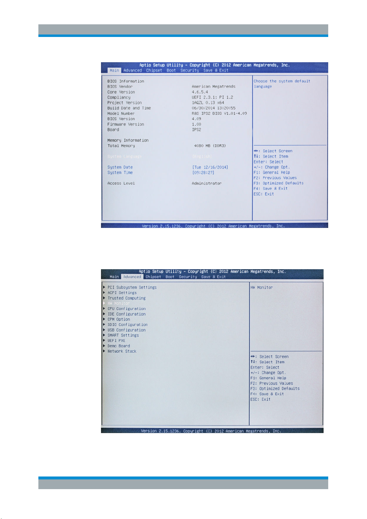
The BIOS settings are displayed.
43Getting Started 2113.7619.02 ─ 12
Page 50
R&S® DVMS1
Installed Software
Backup and Restore of the System Partition
Tip: The navigation in the BIOS settings is explained in the lower right pane.
4. Select the "Advanced" tab.
5. Select "HW Monitor".
6. Press ENTER.
44Getting Started 2113.7619.02 ─ 12
Page 51
R&S® DVMS1
Installed Software
Backup and Restore of the System Partition
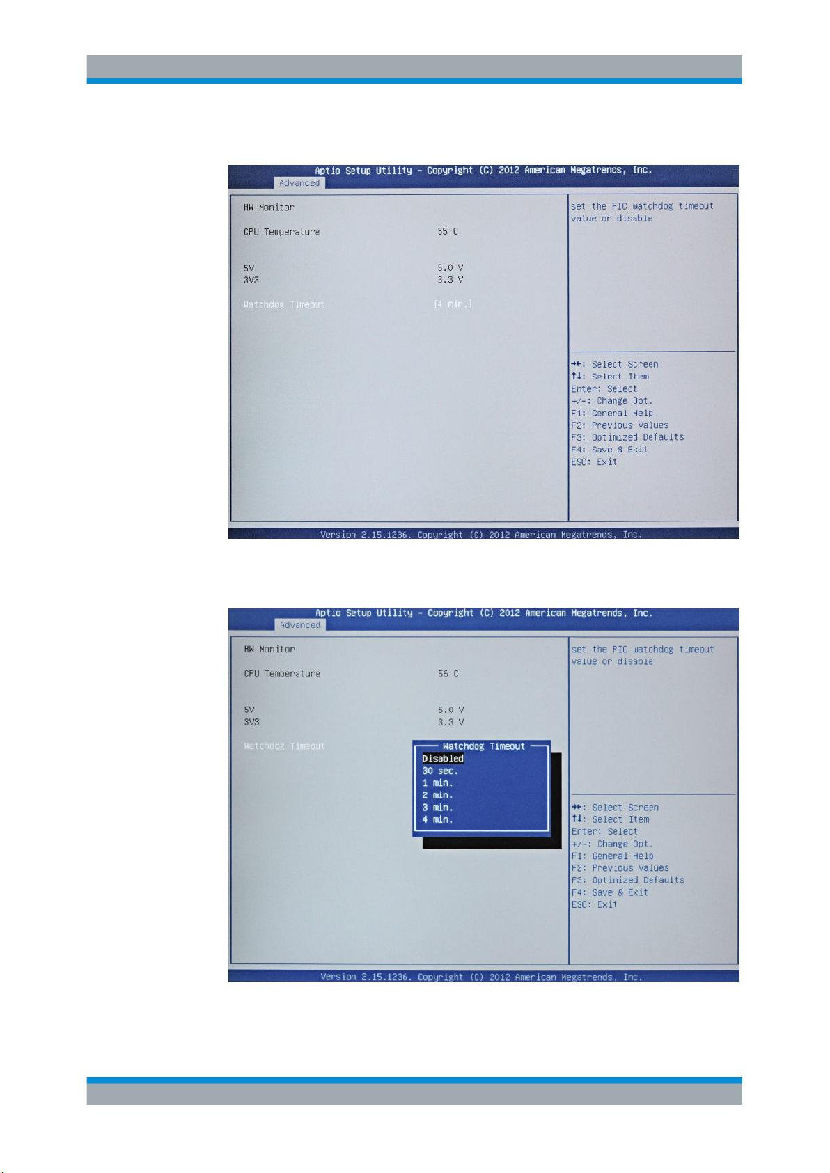
"Watchdog Timeout" is already selected.
7. Press ENTER to open the "Watchdog Timeout" dialog.
8. Select "Disabled".
9. Press ENTER.
45Getting Started 2113.7619.02 ─ 12
Page 52
R&S® DVMS1
Installed Software
Backup and Restore of the System Partition
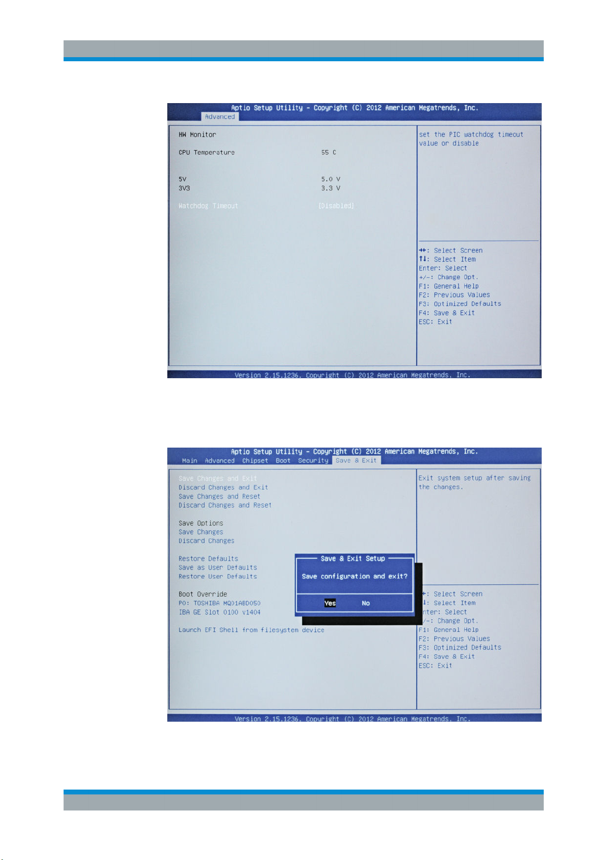
10. Select the "Save & Exit" tab.
"Save Changes and Exit" is already selected.
11. Press ENTER.
12. Press ENTER to save the changes and proceed with the system boot.
46Getting Started 2113.7619.02 ─ 12
Page 53
R&S® DVMS1
8.3.2 Backup and Restore Application
Installed Software
Backup and Restore of the System Partition
13. Continue as described in Chapter 8.3.2, "Backup and Restore Application",
on page 47.
After a successful boot with the default option "Firmware" in the boot dialog or a
restored backup, the hardware watchdog will automatically be re-enabled by the
R&S DVMS system software. Make sure that the required sequence as described
above is not interrupted for some reason. Otherwise restart at step step 2.
Using the backup and restore application, you can back up the instrument installations
and their configuration so that they can be restored if necessary. When restoring, you
can choose between various states.
●
Factory default state
If, for example, the system crashes, you can restore the factory default state.
●
Intermediate states that you have saved
For example, you can back up the current system partition before a firmware
update or provide different system configurations for different environments.
In the restore process, the system partition is deleted, formatted and written newly. The
data partition is not affected.
Connect an external keyboard.
If the instrument does not have a monitor, connect also an external monitor.
To display the main dialog for backup and restore
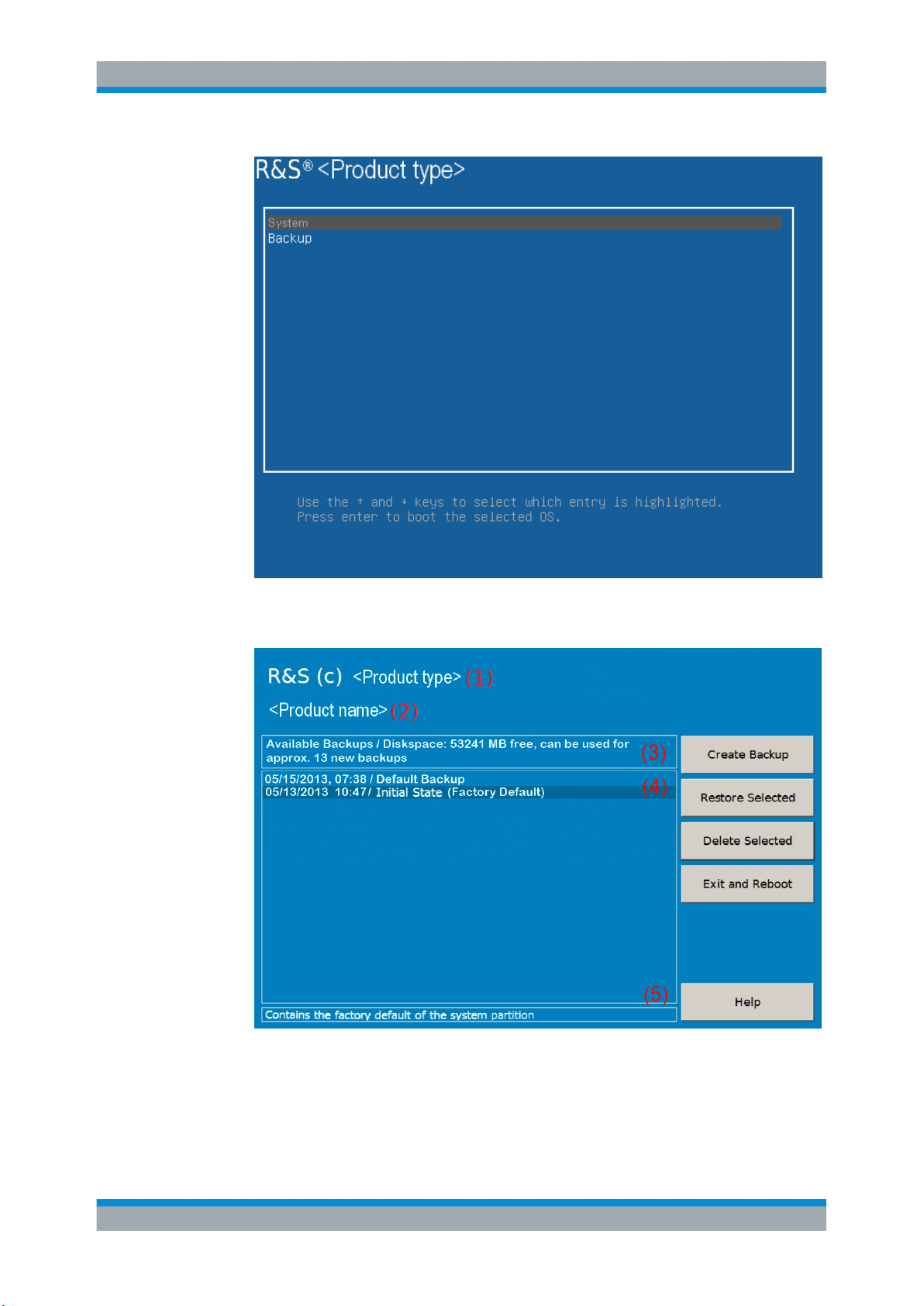
1. Restart the R&S DVMS.
The boot screen is displayed. By default, "System" is selected. If you do not perform the next step within 4 seconds, the dialog vanishes and the booting process
continues.
2. Select the "Backup" partition and press [ENTER].
47Getting Started 2113.7619.02 ─ 12
Page 54
R&S® DVMS1
Installed Software
Backup and Restore of the System Partition
The main dialog is displayed. It provides access to all functions of the backup and
restore application.
Figure 8-1: Main dialog (example)
48Getting Started 2113.7619.02 ─ 12
Page 55
R&S® DVMS1
8.3.2.1 Creating a Backup
Installed Software
Backup and Restore of the System Partition
(1) = Header showing instrument type
(2) = Header showing instrument name
(3) = Free memory space on backup partition
(4) = List of backups already created
(5) = Description of currently selected backup
To continue, see one of the following chapters:
●
Chapter 8.3.2.1, "Creating a Backup", on page 49
●
Chapter 8.3.2.2, "Restoring a Selected Backup Version", on page 50
●
Chapter 8.3.2.3, "Deleting a Backup", on page 50
Using this function, you can create a backup of the current instrument installation and
its configuration.
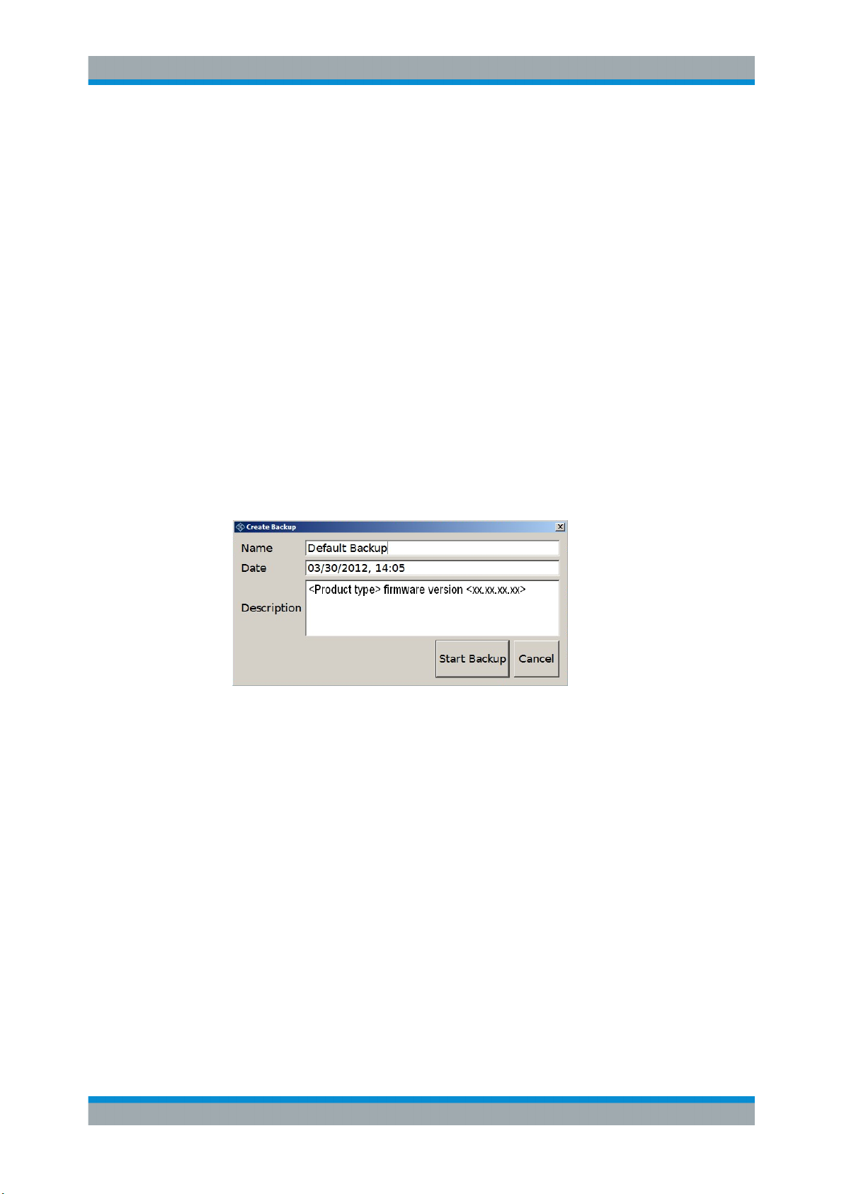
1. In the main dialog (see Figure 8-1), select "Create Backup".
The "Create Backup" dialog is displayed. Under "Description", the current version
of the firmware is displayed.
2. Enter a name for the backup and the date. If necessary, you can add information to
the description.
3. Select "Start Backup".
During the backup process, a progress information dialog is displayed. You can terminate at any time ("Cancel").
After the process has been finished, the dialog is closed automatically, and the
main dialog is displayed again.
Note: If you activate "Keep open when finished", the progress information dialog
remains open until you close it.
4. In the main dialog, select "Exit and Reboot".
The backup and restore application is closed, and the R&S DVMS is restarted.
49Getting Started 2113.7619.02 ─ 12
Page 56
R&S® DVMS1
8.3.2.2 Restoring a Selected Backup Version
Installed Software
Backup and Restore of the System Partition
Using this function, you can restore the selected instrument installation and its configuration.
Malware protection
When restoring a backup, the Windows operating system and installed anti-malware
software are probably outdated. To minimize the risk of malware threats after restoring
a backup, verify and adjust the "Windows Update" settings. Follow the recommendations from Rohde & Schwarz applicable to your instrument. Also, install all Windows
security updates that have been published in the meanwhile.
1. In the main dialog (see Figure 8-1), select the backup you want to restore.
2. Select "Restore Selected".
3. In the "Restore Selected" dialog, select "Yes".
During the restoring process, a progress information dialog is displayed. You can
terminate at any time ("Cancel").
After the process has been finished, the application is closed automatically, and the
R&S DVMS is restarted.
Note: If you activate "Keep open when finished", the progress information dialog
remains open until you close it.
8.3.2.3 Deleting a Backup
Using this function, you can delete the selected instrument installation and its configuration.
To provide space for new backups, you can remove older backups. The factory default
cannot be deleted.
1. In the main dialog (see Figure 8-1), select the backup you want to delete.
2. Select "Delete Selected".
3. In the "Delete Selected" dialog, select "Yes".
Note: You are not authorized to delete a factory default backup. If you have
selected one, an error message is displayed and the backup is not deleted.
4. In the main dialog, select "Exit and Reboot", or continue with Chapter 8.3.2.1, "Cre-
ating a Backup", on page 49.
50Getting Started 2113.7619.02 ─ 12
Page 57
R&S® DVMS1
9.1 Cleaning the Instrument
Maintenance
Replacing the Fuses
9 Maintenance
The R&S DVMS does not need periodic maintenance. Clean the outside of the instrument when necessary and check the rated data from time to time.
If any problem arises, contact one of our customer support centers. The addresses of
our customer support centers are provided at the beginning of this manual.
Shock hazard
Before cleaning the R&S DVMS, make sure that the R&S DVMS is switched off and
disconnected from all power supplies.
1. Clean the outside of the R&S DVMS using a soft, lint–free dust cloth.
2. Make sure that vents are unobstructed.
Instrument damage caused by cleaning agents
Cleaning agents contain substances that can damage the R&S DVMS, e.g. cleaning
agents that contain a solvent can damage the front panel labeling or plastic parts.
Never use cleaning agents such as solvents (thinners, acetone, etc.), acids, bases, or
other substances.
9.2 Replacing the Fuses
The R&S DVMS is protected by two fuses (IEC 127 – T 2.0 H/250 V) on the rear panel
next to the AC power switch.
Shock hazard
Before replacing a fuse, make sure that the R&S DVMS is switched off and disconnected from all power supplies.
Always use fuses supplied by Rohde & Schwarz as spare parts, or fuses of the same
type and rating.
51Getting Started 2113.7619.02 ─ 12
Page 58

R&S® DVMS1
9.3 Storing the Instrument
Maintenance
Storing the Instrument
To replace the fuses
1. Open the lid of the AC power connector.
2. Lift the fuse holder out of its slot.
3. Exchange the two fuses.
4. Put the fuse holder back in its slot.
5. Close the lid.
The storage temperature range of the R&S DVMS is given in the data sheet. If the
R&S DVMS is to be stored for a longer period of time, it must be protected against
dust.
Repack the R&S DVMS as it was originally packed when transporting or shipping. The
two protective foam plastic parts prevent the control elements and connectors from
being damaged. The antistatic packing foil avoids any undesired electrostatic charging
to occur.
If you do not use the original packaging, provide for sufficient padding to prevent the
R&S DVMS from slipping inside the package. Wrap antistatic packing foil around the
R&S DVMS to protect it from electrostatic charging.
52Getting Started 2113.7619.02 ─ 12
Page 59

R&S® DVMS1
Index
Index
Symbols
1 PPS REF IN connector .................................................. 16
10 MHz REF IN connector ................................................ 15
A
AC power supply connector .............................................. 15
AC power switch ............................................................... 15
Activating the TS bit rate monitoring (example) ................ 35
Administrator ID ................................................................ 42
AF OUT connector ............................................................ 14
B
Backup
Creating ...................................................................... 49
Deleting ....................................................................... 50
Main dialog ................................................................. 47
Prerequisite ................................................................. 43
Restoring .................................................................... 50
System partition .......................................................... 43
Bench operation ................................................................ 11
C
Checking
Accessories ................................................................. 11
Provided options ......................................................... 29
Checking the gross bit rate (example) .............................. 32
Checking the net bit rate (example) .................................. 33
Checking the PSI table PAT (example) ............................. 36
Checking the TS synchronization (example) ..................... 31
Computer name ................................................................ 41
Connecting
External devices ......................................................... 26
Power supply .............................................................. 26
Connector
1 PPS REF IN ............................................................. 16
10 MHz REF IN ........................................................... 15
AC power supply ......................................................... 15
AF OUT (headphones) ............................................... 14
DVI-D .......................................................................... 16
Local area network (LAN) ........................................... 17
USB ............................................................................ 18
Conventions ........................................................................ 9
Creating a basic configuration (example) .......................... 31
D
Designated purpose ............................................................ 7
Documentation .................................................................... 8
Getting started .............................................................. 8
On the R&S DVMS ....................................................... 8
Online help .................................................................... 8
User manual ................................................................. 8
DVB-T/H receiver module ................................................. 18
DVB-T/T2 receiver module ................................................ 19
DVB-T2 receiver module ................................................... 20
DVI-D connector ................................................................ 16
E
External devices ................................................................ 26
F
Firewall settings ................................................................ 41
Firmware
Options ....................................................................... 29
Update ........................................................................ 42
Front panel ........................................................................ 13
Fuse
Replacing .................................................................... 51
G
Getting started manual ........................................................ 8
H
Help menu ........................................................................... 8
Help system ........................................................................ 8
Host name ......................................................................... 41
I
Information
R&S homepage ............................................................ 7
Safety issues ................................................................ 7
INSTRUMENT READY status display .............................. 14
IP address
Changing .................................................................... 40
L
Local area network (LAN) ................................................. 38
Local area network (LAN) connector ................................. 17
Login
Windows 7 .................................................................. 42
M
Maintenance ...................................................................... 51
Manual
Getting started .............................................................. 8
On the R&S DVMS ....................................................... 8
User manual ................................................................. 8
Measurement example ...................................................... 30
Activating the TS bit rate monitoring ........................... 35
Checking the gross bit rate ......................................... 32
Checking the net bit rate ............................................. 33
Checking the PSI table PAT ........................................ 36
Checking the TS synchronization ............................... 31
Creating a basic configuration .................................... 31
Requirements ............................................................. 30
Setup .......................................................................... 30
Module
DVB-T/H receiver ........................................................ 18
DVB-T/T2 receiver ...................................................... 19
DVB-T2 receiver ......................................................... 20
S/S2 receiver .............................................................. 22
single TS input ............................................................ 21
TS/IP interface ............................................................ 24
Electromagnetic interference ............................................ 26
53Getting Started 2113.7619.02 ─ 12
Page 60

R&S® DVMS1
Index
N
Network
Configuring card ......................................................... 40
Connecting to .............................................................. 39
Disconnecting from ..................................................... 39
Non-volatile RAM .............................................................. 29
O
Online help .......................................................................... 8
Operating system .............................................................. 42
Options
Checking ..................................................................... 29
Firmware ..................................................................... 29
P
Packing the instrument ...................................................... 52
Password
Windows 7 .................................................................. 42
POWER status display ...................................................... 13
Power supply
Connecting to .............................................................. 26
Product
Documentation .............................................................. 8
Internet site ................................................................... 7
Provided options
Checking ..................................................................... 29
Purpose ............................................................................... 7
Putting up the instrument ................................................... 11
R
Rack mounting .................................................................. 12
RAM
Non-volatile ................................................................. 29
Rear panel ......................................................................... 14
REMOTE status display .................................................... 14
Replacing fuses ................................................................. 51
Restore
Main dialog ................................................................. 47
Prerequisite ................................................................. 43
System partition .......................................................... 43
Status display
INSTRUMENT READY ............................................... 14
POWER ...................................................................... 13
REMOTE .................................................................... 14
Storing the instrument ....................................................... 52
Switching off the instrument .............................................. 29
Switching on the instrument .............................................. 28
System partition
Backup ........................................................................ 49
Deleting selected version ............................................ 50
Prerequisite for backup/restore ................................... 43
Restoring selected version ......................................... 50
T
TCP/IP protocol
Configuring ................................................................. 40
TS/IP interface module ...................................................... 24
U
Unpacking the cardboard box ........................................... 10
USB connector .................................................................. 18
External devices ......................................................... 26
User manual ........................................................................ 8
User name
Windows 7 .................................................................. 42
W
Warranty ............................................................................ 11
Watchdog
Disabling ..................................................................... 43
Windows 7 ......................................................................... 42
Administrator ID .......................................................... 42
Login ........................................................................... 42
Password .................................................................... 42
Prerequisite for backup/restore ................................... 43
Start menu .................................................................. 43
User name .................................................................. 42
S
S/S2 receiver module ........................................................ 22
Safety information ............................................................... 7
Sample application ............................................................ 30
Activating the TS bit rate monitoring ........................... 35
Checking the gross bit rate ......................................... 32
Checking the net bit rate ............................................. 33
Checking the PSI table PAT ........................................ 36
Checking the TS synchronization ............................... 31
Creating a basic configuration .................................... 31
Requirements ............................................................. 30
Setup .......................................................................... 30
Shipping damage inspection ............................................. 10
Single TS input module ..................................................... 21
Software
Installing ...................................................................... 43
Software options
Installing ...................................................................... 42
Start menu ......................................................................... 43
54Getting Started 2113.7619.02 ─ 12
 Loading...