

Page 1

CSD5 Servo Drive
User Manual
Catalog Number(s): CSD5_xxBX1
Page 2
Important User Information
WARNING
IMPORTANT
CAUTION
Solid state equipment has operational characteristics differing from those of electromechanical equipment. There are some important
differences between solid state equipment and hard-wired electromechanical devices. Because of this difference, and also because of the
wide variety of uses for solid state equipment, all persons responsible for applying this equipment must satisfy themselves that each
intended application of this equipment is acceptable.
In no event will RS Automation Co., Ltd. be responsible or liable for indirect or consequential damages resulting from the use or
application of this equipment.
The examples and diagrams in this manual are included solely for illustrative purposes. Because of the many variables and requirements
associated with any particular installation, RS Automation Co., Ltd. cannot assume responsibility or liability for actual use based on the
examples and diagrams.
No patent liability is assumed by RS Automation Co., Ltd. with respect to use of information, circuits, equipment, or software described in
this manual.
Reproduction of the contents of this manual, in whole or in part, without written permission of RS Automation Co., Ltd., is prohibited.
Throughout this manual, when necessary, we use notes to make you aware of safety considerations.
Identifies information about practices or circumstances which may lead to serious personal injury or death, properity
damage, or economic loss.
Identifies information that is critical for successful application and understanding of the product.
Idnetifies information about proctives or circumstances that can lead to minor personal injury, properity damage,
ecconomic loss, or product malfuntion. However, depending on the situraiton, failutre to follow the directions
accompanying this symbol may also lead to serious consequences.
Page 3

Summary of Change
You will see change bars to the left or right of a paragraph throughout this
manual to help you quickly indentify revisions.
Manual
Revision
A N/A Jun 2011
Changes Date
1 CSD5 Servo Drive
Page 4

SOC-2 Summary of Change
CSD5 Servo Drive
Page 5

Summary of Change
Table Of Contents
Preface
Before Using the CSD5 Servo
Drive
Who Should Use This Manual . . . . . . . . . . . . . . . . . . . . . . . . . . . . . . . . . . . . P-1
About This Publication. . . . . . . . . . . . . . . . . . . . . . . . . . . . . . . . . . . . . . . . . . P-1
Additional Resources . . . . . . . . . . . . . . . . . . . . . . . . . . . . . . . . . . . . . . . . . . . P-1
Conventions Used in This Manual. . . . . . . . . . . . . . . . . . . . . . . . . . . . . . . . . P-1
Table for Parameter Setting. . . . . . . . . . . . . . . . . . . . . . . . . . . . . . . . . . . P-2
Terminology . . . . . . . . . . . . . . . . . . . . . . . . . . . . . . . . . . . . . . . . . . . . . . . P-3
Notation Description. . . . . . . . . . . . . . . . . . . . . . . . . . . . . . . . . . . . . . . . P-3
Manual Description Order . . . . . . . . . . . . . . . . . . . . . . . . . . . . . . . . . . . P-5
Others. . . . . . . . . . . . . . . . . . . . . . . . . . . . . . . . . . . . . . . . . . . . . . . . . . . . P-5
Safety Precautions . . . . . . . . . . . . . . . . . . . . . . . . . . . . . . . . . . . . . . . . . . . . . . P-6
Usage . . . . . . . . . . . . . . . . . . . . . . . . . . . . . . . . . . . . . . . . . . . . . . . . . . . P-6
Storage . . . . . . . . . . . . . . . . . . . . . . . . . . . . . . . . . . . . . . . . . . . . . . . . . . . P-6
Transportation . . . . . . . . . . . . . . . . . . . . . . . . . . . . . . . . . . . . . . . . . . . . P-6
Installation and Wiring . . . . . . . . . . . . . . . . . . . . . . . . . . . . . . . . . . . . . P-7
Maintenance and Repair . . . . . . . . . . . . . . . . . . . . . . . . . . . . . . . . . . . . . P-7
Chapter 1
Product Type and Each Part Name . . . . . . . . . . . . . . . . . . . . . . . . . . . . . . . . 1-1
Model Number of the Drive . . . . . . . . . . . . . . . . . . . . . . . . . . . . . . . . . . . . . 1-2
Name of Each Motor Part . . . . . . . . . . . . . . . . . . . . . . . . . . . . . . . . . . . . . . . 1-3
Model Number of the Motor . . . . . . . . . . . . . . . . . . . . . . . . . . . . . . . . . . . . . 1-4
Installation
Wiring
Chapter 2
Servo Drive Installation . . . . . . . . . . . . . . . . . . . . . . . . . . . . . . . . . . . . . . . . . 2-1
Precautions . . . . . . . . . . . . . . . . . . . . . . . . . . . . . . . . . . . . . . . . . . . . . . . . 2-1
Installation Environment. . . . . . . . . . . . . . . . . . . . . . . . . . . . . . . . . . . . . 2-4
Servo Motor Installation. . . . . . . . . . . . . . . . . . . . . . . . . . . . . . . . . . . . . . . . . 2-4
Chapter 3
Before You Begin . . . . . . . . . . . . . . . . . . . . . . . . . . . . . . . . . . . . . . . . . . . . . . 3-1
Electric Circuit . . . . . . . . . . . . . . . . . . . . . . . . . . . . . . . . . . . . . . . . . . . . . . . . 3-2
Name and Function . . . . . . . . . . . . . . . . . . . . . . . . . . . . . . . . . . . . . . . . . 3-2
AC Power Terminal (L1, L2, L3) and Control Power Terminal (L1C, L2C). . . 3-3
Regenerative Register Connection Port . . . . . . . . . . . . . . . . . . . . . . . . . 3-4
Electric Circuit Diagram . . . . . . . . . . . . . . . . . . . . . . . . . . . . . . . . . . . . . 3-5
Using the Socket and Lever. . . . . . . . . . . . . . . . . . . . . . . . . . . . . . . . . . . 3-6
I/O Signal (I/O). . . . . . . . . . . . . . . . . . . . . . . . . . . . . . . . . . . . . . . . . . . . . . . 3-8
I/O Connection Diagram . . . . . . . . . . . . . . . . . . . . . . . . . . . . . . . . . . . . 3-8
(I/O) Input Signal. . . . . . . . . . . . . . . . . . . . . . . . . . . . . . . . . . . . . . . . . . . . . 3-10
Sequence Input Signal (Allocation) . . . . . . . . . . . . . . . . . . . . . . . . . . . . 3-10
General Input Signal (Fixed) . . . . . . . . . . . . . . . . . . . . . . . . . . . . . . . . . 3-11
(I/O) Output Signal . . . . . . . . . . . . . . . . . . . . . . . . . . . . . . . . . . . . . . . . . . . 3-13
Sequence Output Signal (Allocation) . . . . . . . . . . . . . . . . . . . . . . . . . . 3-13
General Output Signal (Fixed) . . . . . . . . . . . . . . . . . . . . . . . . . . . . . . . 3-14
(I/O) Input Circuit and Interface . . . . . . . . . . . . . . . . . . . . . . . . . . . . . . . . 3-16
i CSD5 Servo Drive
Page 6

ii
Operator, Basic Setting and
Startup
Pulse Command Input Circuit . . . . . . . . . . . . . . . . . . . . . . . . . . . . . . . 3-16
Analog Voltage Input Circuit . . . . . . . . . . . . . . . . . . . . . . . . . . . . . . . . 3-17
Sequence Input Circuit . . . . . . . . . . . . . . . . . . . . . . . . . . . . . . . . . . . . . 3-18
Emergency Stop Signal . . . . . . . . . . . . . . . . . . . . . . . . . . . . . . . . . . . . . 3-19
(I/O) Output Circuit and Interface . . . . . . . . . . . . . . . . . . . . . . . . . . . . . . . 3-20
Line Drive Output . . . . . . . . . . . . . . . . . . . . . . . . . . . . . . . . . . . . . . . . . 3-20
Photo-Coupler Output . . . . . . . . . . . . . . . . . . . . . . . . . . . . . . . . . . . . . 3-20
Encoder Wiring (Motor Feedback) . . . . . . . . . . . . . . . . . . . . . . . . . . . . . . . 3-22
Pin Arrangement of Motor Feedback. . . . . . . . . . . . . . . . . . . . . . . . . . 3-22
Terminal Type . . . . . . . . . . . . . . . . . . . . . . . . . . . . . . . . . . . . . . . . . . . . 3-23
Encoder Signal Process . . . . . . . . . . . . . . . . . . . . . . . . . . . . . . . . . . . . . 3-24
General Articles Wiring . . . . . . . . . . . . . . . . . . . . . . . . . . . . . . . . . . . . . . . . 3-27
Precautions . . . . . . . . . . . . . . . . . . . . . . . . . . . . . . . . . . . . . . . . . . . . . . . 3-27
Capacity of the Drive and Fuse. . . . . . . . . . . . . . . . . . . . . . . . . . . . . . . 3-28
Noise Protection . . . . . . . . . . . . . . . . . . . . . . . . . . . . . . . . . . . . . . . . . . 3-29
Wiring when Using Several Drives . . . . . . . . . . . . . . . . . . . . . . . . . . . . 3-33
Connection to Peripheral Equipment . . . . . . . . . . . . . . . . . . . . . . . . . . 3-34
Chapter 4
Before You Begin . . . . . . . . . . . . . . . . . . . . . . . . . . . . . . . . . . . . . . . . . . . . . . 4-1
About Servo-ON Signal . . . . . . . . . . . . . . . . . . . . . . . . . . . . . . . . . . . . . 4-1
Operator . . . . . . . . . . . . . . . . . . . . . . . . . . . . . . . . . . . . . . . . . . . . . . . . . . . . . 4-4
Name and Function of Each Part . . . . . . . . . . . . . . . . . . . . . . . . . . . . . . 4-4
Icons for the Key Buttons. . . . . . . . . . . . . . . . . . . . . . . . . . . . . . . . . . . . 4-4
Structure of the Entire Mode . . . . . . . . . . . . . . . . . . . . . . . . . . . . . . . . . 4-5
Status Display Mode . . . . . . . . . . . . . . . . . . . . . . . . . . . . . . . . . . . . . . . . 4-7
Overview of the Parameter Setting Mode . . . . . . . . . . . . . . . . . . . . . . . 4-9
Overview of the Monitor Mode . . . . . . . . . . . . . . . . . . . . . . . . . . . . . . 4-10
Overview of the Operation Mode. . . . . . . . . . . . . . . . . . . . . . . . . . . . . 4-11
Basic Setting . . . . . . . . . . . . . . . . . . . . . . . . . . . . . . . . . . . . . . . . . . . . . . . . . 4-12
Overview of the Basic Setting . . . . . . . . . . . . . . . . . . . . . . . . . . . . . . . . 4-12
Control Mode Setting . . . . . . . . . . . . . . . . . . . . . . . . . . . . . . . . . . . . . . 4-13
Motor Setting . . . . . . . . . . . . . . . . . . . . . . . . . . . . . . . . . . . . . . . . . . . . . . . . 4-16
Startup . . . . . . . . . . . . . . . . . . . . . . . . . . . . . . . . . . . . . . . . . . . . . . . . . . . . . . 4-21
Before Startup . . . . . . . . . . . . . . . . . . . . . . . . . . . . . . . . . . . . . . . . . . . . 4-21
Startup . . . . . . . . . . . . . . . . . . . . . . . . . . . . . . . . . . . . . . . . . . . . . . . . . . 4-21
Function for Control Mode
Chapter 5
Sequence I/O (Input/Output) Signal . . . . . . . . . . . . . . . . . . . . . . . . . . . . . . 5-1
What is Sequence I/O Signal?. . . . . . . . . . . . . . . . . . . . . . . . . . . . . . . . . 5-1
Function of Input Signal . . . . . . . . . . . . . . . . . . . . . . . . . . . . . . . . . . . . . 5-2
Function of Output Signal. . . . . . . . . . . . . . . . . . . . . . . . . . . . . . . . . . . . 5-4
Input Signal Allocation Method . . . . . . . . . . . . . . . . . . . . . . . . . . . . . . . 5-5
Output Signal Allocation Method . . . . . . . . . . . . . . . . . . . . . . . . . . . . . . 5-7
Notice for Signal Allocation . . . . . . . . . . . . . . . . . . . . . . . . . . . . . . . . . . 5-8
Position Control Mode . . . . . . . . . . . . . . . . . . . . . . . . . . . . . . . . . . . . . . . . . 5-10
Overview . . . . . . . . . . . . . . . . . . . . . . . . . . . . . . . . . . . . . . . . . . . . . . . . 5-10
Standard Wiring Example . . . . . . . . . . . . . . . . . . . . . . . . . . . . . . . . . . . 5-11
Page 7

iii
Position Command Pulse . . . . . . . . . . . . . . . . . . . . . . . . . . . . . . . . . . . 5-11
Position Command Pulse Setting . . . . . . . . . . . . . . . . . . . . . . . . . . . . . 5-15
Electrical Specifications of Position Command Pulse . . . . . . . . . . . . . 5-17
Electronic Gear . . . . . . . . . . . . . . . . . . . . . . . . . . . . . . . . . . . . . . . . . . . 5-18
Position Error Clear </PCLR> . . . . . . . . . . . . . . . . . . . . . . . . . . . . . . 5-25
Pulse Command Inhibition</INHIB> Input . . . . . . . . . . . . . . . . . . . 5-25
Expansion of Electronic Gear Setting . . . . . . . . . . . . . . . . . . . . . . . . . 5-26
The Second Group of Electronic Gear </GEAR> Input . . . . . . . . . 5-27
Position Completion Signal Detection </P-COM>, Approach Signal
Detection </NEAR> Output . . . . . . . . . . . . . . . . . . . . . . . . . . . . . . . 5-28
Output Width of Allowable Position Error . . . . . . . . . . . . . . . . . . . . . 5-31
Input / Output Signal Timing Diagram . . . . . . . . . . . . . . . . . . . . . . . . 5-31
Speed Control Mode. . . . . . . . . . . . . . . . . . . . . . . . . . . . . . . . . . . . . . . . . . . 5-32
Overview . . . . . . . . . . . . . . . . . . . . . . . . . . . . . . . . . . . . . . . . . . . . . . . . 5-32
Standard Wiring Example . . . . . . . . . . . . . . . . . . . . . . . . . . . . . . . . . . . 5-33
Speed Command Input . . . . . . . . . . . . . . . . . . . . . . . . . . . . . . . . . . . . . 5-34
Zero Clamp </Z-CLP> Input . . . . . . . . . . . . . . . . . . . . . . . . . . . . . . . 5-35
Rotation Direction Switch Input </C-DIR> . . . . . . . . . . . . . . . . . . . 5-36
Motor Rotation Start/Stop Input</START> . . . . . . . . . . . . . . . . . . . 5-37
Speed Coincidence Output Signal </V-COM> . . . . . . . . . . . . . . . . . 5-38
Rotation Detection </TG-ON> Output . . . . . . . . . . . . . . . . . . . . . . 5-39
Speed Limit Function and Speed Limit Detection </V-LMT> Output . . . 5-41
Torque Control Mode. . . . . . . . . . . . . . . . . . . . . . . . . . . . . . . . . . . . . . . . . . 5-43
Overview . . . . . . . . . . . . . . . . . . . . . . . . . . . . . . . . . . . . . . . . . . . . . . . . 5-43
Standard Wiring Example . . . . . . . . . . . . . . . . . . . . . . . . . . . . . . . . . . . 5-44
Torque Command Input . . . . . . . . . . . . . . . . . . . . . . . . . . . . . . . . . . . . 5-44
Torque Limit and Torque Limit Detection </T-LMT> Output . . . . 5-46
Multi-Step Speed Mode . . . . . . . . . . . . . . . . . . . . . . . . . . . . . . . . . . . . . . . . 5-51
Overview . . . . . . . . . . . . . . . . . . . . . . . . . . . . . . . . . . . . . . . . . . . . . . . . 5-51
Standard Wiring Example . . . . . . . . . . . . . . . . . . . . . . . . . . . . . . . . . . . 5-52
Multi-Step Speed Command Setting . . . . . . . . . . . . . . . . . . . . . . . . . . . 5-52
Mixed Control Mode and </C-SEL> Function. . . . . . . . . . . . . . . . . . . . . 5-56
Tuning by Gain Setting
Chapter 6
Before You Begin . . . . . . . . . . . . . . . . . . . . . . . . . . . . . . . . . . . . . . . . . . . . . . 6-1
Mark Description . . . . . . . . . . . . . . . . . . . . . . . . . . . . . . . . . . . . . . . . . . . 6-1
Gain Introduction . . . . . . . . . . . . . . . . . . . . . . . . . . . . . . . . . . . . . . . . . . 6-1
Inertia Ratio . . . . . . . . . . . . . . . . . . . . . . . . . . . . . . . . . . . . . . . . . . . . . . . 6-4
Gain Setting Configuration. . . . . . . . . . . . . . . . . . . . . . . . . . . . . . . . . . . . . . . 6-5
Auto Gain Setting . . . . . . . . . . . . . . . . . . . . . . . . . . . . . . . . . . . . . . . . . . . . . . 6-8
Auto Tuning. . . . . . . . . . . . . . . . . . . . . . . . . . . . . . . . . . . . . . . . . . . . . . . 6-8
Off-line Auto Tuning. . . . . . . . . . . . . . . . . . . . . . . . . . . . . . . . . . . . . . . . 6-8
On-line Auto Tuning . . . . . . . . . . . . . . . . . . . . . . . . . . . . . . . . . . . . . . . 6-10
On-line Vibration Suppression . . . . . . . . . . . . . . . . . . . . . . . . . . . . . . . 6-11
Online Vibration Suppression Gain Setting . . . . . . . . . . . . . . . . . . . . . 6-13
Manual Gain Setting . . . . . . . . . . . . . . . . . . . . . . . . . . . . . . . . . . . . . . . . . . . 6-14
Gain Setting Flowchart . . . . . . . . . . . . . . . . . . . . . . . . . . . . . . . . . . . . . 6-14
Basic Gain Setting . . . . . . . . . . . . . . . . . . . . . . . . . . . . . . . . . . . . . . . . . 6-15
Position, Speed, Torque Related Gain Setting. . . . . . . . . . . . . . . . . . . . . . . 6-18
Page 8

iv
Applications
Torque Control Related Gain . . . . . . . . . . . . . . . . . . . . . . . . . . . . . . . . 6-19
Speed Control Related Gain . . . . . . . . . . . . . . . . . . . . . . . . . . . . . . . . . 6-21
Position Control Related Gain . . . . . . . . . . . . . . . . . . . . . . . . . . . . . . . 6-25
Tip to get fast response . . . . . . . . . . . . . . . . . . . . . . . . . . . . . . . . . . . . . . . . 6-27
Feedforward function . . . . . . . . . . . . . . . . . . . . . . . . . . . . . . . . . . . . . . 6-27
Speed Bias Function . . . . . . . . . . . . . . . . . . . . . . . . . . . . . . . . . . . . . . . 6-28
P/PI Mode Setting Function. . . . . . . . . . . . . . . . . . . . . . . . . . . . . . . . . 6-30
Initial Torque Bias . . . . . . . . . . . . . . . . . . . . . . . . . . . . . . . . . . . . . . . . . 6-33
</G-SEL> Function. . . . . . . . . . . . . . . . . . . . . . . . . . . . . . . . . . . . . . . 6-36
Gain Switching Function. . . . . . . . . . . . . . . . . . . . . . . . . . . . . . . . . . . . 6-37
Chapter 7
Motor Suspension . . . . . . . . . . . . . . . . . . . . . . . . . . . . . . . . . . . . . . . . . . . . . . 7-1
Overview . . . . . . . . . . . . . . . . . . . . . . . . . . . . . . . . . . . . . . . . . . . . . . . . . 7-1
Servo Alarm . . . . . . . . . . . . . . . . . . . . . . . . . . . . . . . . . . . . . . . . . . . . . . . 7-1
OverTravel <P-OT>, <N-OT>. . . . . . . . . . . . . . . . . . . . . . . . . . . . . . . 7-2
Dynamic Brake. . . . . . . . . . . . . . . . . . . . . . . . . . . . . . . . . . . . . . . . . . . . . 7-3
Motor Brake Contorl . . . . . . . . . . . . . . . . . . . . . . . . . . . . . . . . . . . . . . . . . . . 7-6
Change the Motor Rotation Direction. . . . . . . . . . . . . . . . . . . . . . . . . . . . . 7-11
Reneration Resister . . . . . . . . . . . . . . . . . . . . . . . . . . . . . . . . . . . . . . . . . . . . 7-12
Reneration Resister . . . . . . . . . . . . . . . . . . . . . . . . . . . . . . . . . . . . . . . . 7-12
External Regenerative Resistor . . . . . . . . . . . . . . . . . . . . . . . . . . . . . . . 7-13
Regenerative Resistor Selection Standard. . . . . . . . . . . . . . . . . . . . . . . 7-14
Setting for Smooth Operation . . . . . . . . . . . . . . . . . . . . . . . . . . . . . . . . . . . 7-17
Speed Limiting Function . . . . . . . . . . . . . . . . . . . . . . . . . . . . . . . . . . . . . . . 7-21
Postion Feedback to the Host Controller . . . . . . . . . . . . . . . . . . . . . . . . . . 7-24
Overview . . . . . . . . . . . . . . . . . . . . . . . . . . . . . . . . . . . . . . . . . . . . . . . . 7-24
Direction Change of Output Pulse . . . . . . . . . . . . . . . . . . . . . . . . . . . . 7-24
Pulse Dividing Circuit . . . . . . . . . . . . . . . . . . . . . . . . . . . . . . . . . . . . . . 7-25
Analog Monitor Output . . . . . . . . . . . . . . . . . . . . . . . . . . . . . . . . . . . . . . . . 7-28
Use of Absolute Encoder . . . . . . . . . . . . . . . . . . . . . . . . . . . . . . . . . . . . . . . 7-31
What is an Absolute Encoder? . . . . . . . . . . . . . . . . . . . . . . . . . . . . . . . 7-31
Contact with the Host Controller . . . . . . . . . . . . . . . . . . . . . . . . . . . . . 7-32
Battery. . . . . . . . . . . . . . . . . . . . . . . . . . . . . . . . . . . . . . . . . . . . . . . . . . . 7-33
Reset of Absolute Encoder . . . . . . . . . . . . . . . . . . . . . . . . . . . . . . . . . . 7-34
Data Transmission of Absolute Encoder . . . . . . . . . . . . . . . . . . . . . . . 7-36
Operation Mode Function . . . . . . . . . . . . . . . . . . . . . . . . . . . . . . . . . . . . . . 7-41
Things to Know First . . . . . . . . . . . . . . . . . . . . . . . . . . . . . . . . . . . . . . 7-41
Jog Operation (run-00) . . . . . . . . . . . . . . . . . . . . . . . . . . . . . . . . . . . . . 7-41
Off-line Auto Tuning Operation (run-01) . . . . . . . . . . . . . . . . . . . . . . 7-43
Auto Adjustment of Speed Command Offset (run-03) . . . . . . . . . . . . 7-44
Auto Adjustment of Torque Command Offset (run-04). . . . . . . . . . . 7-46
Alarm Reset (run-08) . . . . . . . . . . . . . . . . . . . . . . . . . . . . . . . . . . . . . . . 7-49
Absolute Encoder Reset (run-10) . . . . . . . . . . . . . . . . . . . . . . . . . . . . . 7-50
2-Group Gain Storing (run-11) . . . . . . . . . . . . . . . . . . . . . . . . . . . . . . . 7-50
Parameter Initialization (run-12) . . . . . . . . . . . . . . . . . . . . . . . . . . . . . . 7-50
Monitor Mode Function. . . . . . . . . . . . . . . . . . . . . . . . . . . . . . . . . . . . . . . . 7-52
Monitor Mode Function . . . . . . . . . . . . . . . . . . . . . . . . . . . . . . . . . . . . 7-54
Key Button Operation. . . . . . . . . . . . . . . . . . . . . . . . . . . . . . . . . . . . . . 7-55
Page 9

Inspection and Protection
Functions
Parameter Group
v
Chapter 8
Inspection . . . . . . . . . . . . . . . . . . . . . . . . . . . . . . . . . . . . . . . . . . . . . . . . . . . . 8-1
Inspection of Motor. . . . . . . . . . . . . . . . . . . . . . . . . . . . . . . . . . . . . . . . . 8-1
Inspection of Drive . . . . . . . . . . . . . . . . . . . . . . . . . . . . . . . . . . . . . . . . . 8-2
Part Inspection. . . . . . . . . . . . . . . . . . . . . . . . . . . . . . . . . . . . . . . . . . . . . 8-2
Battery Inspection for Absolute Encoder. . . . . . . . . . . . . . . . . . . . . . . . 8-3
Protection Function . . . . . . . . . . . . . . . . . . . . . . . . . . . . . . . . . . . . . . . . . . . . 8-3
Servo Warning . . . . . . . . . . . . . . . . . . . . . . . . . . . . . . . . . . . . . . . . . . . . . 8-3
Servo Alarm . . . . . . . . . . . . . . . . . . . . . . . . . . . . . . . . . . . . . . . . . . . . . . . 8-5
Confirmation before Requesting for A/S. . . . . . . . . . . . . . . . . . . . . . . . 8-9
Appedix B
Parameter Description . . . . . . . . . . . . . . . . . . . . . . . . . . . . . . . . . . . . . . . . . . B-1
Standard Group 0 . . . . . . . . . . . . . . . . . . . . . . . . . . . . . . . . . . . . . . . . . . B-1
Standard Group 1 . . . . . . . . . . . . . . . . . . . . . . . . . . . . . . . . . . . . . . . . . . B-3
Standard Group 2 . . . . . . . . . . . . . . . . . . . . . . . . . . . . . . . . . . . . . . . . . . B-6
Standard Group 3 . . . . . . . . . . . . . . . . . . . . . . . . . . . . . . . . . . . . . . . . . . B-7
Standard Group 4 . . . . . . . . . . . . . . . . . . . . . . . . . . . . . . . . . . . . . . . . . . B-7
Standard Group 5 . . . . . . . . . . . . . . . . . . . . . . . . . . . . . . . . . . . . . . . . . . B-8
Parameter Description . . . . . . . . . . . . . . . . . . . . . . . . . . . . . . . . . . . . . . . . . . B-9
Standard Group 0 . . . . . . . . . . . . . . . . . . . . . . . . . . . . . . . . . . . . . . . . . . B-9
Standard Group 1 . . . . . . . . . . . . . . . . . . . . . . . . . . . . . . . . . . . . . . . . . B-25
Standard Group 2 . . . . . . . . . . . . . . . . . . . . . . . . . . . . . . . . . . . . . . . . . B-38
Standard Group 3 . . . . . . . . . . . . . . . . . . . . . . . . . . . . . . . . . . . . . . . . . B-42
Standard Group 4 . . . . . . . . . . . . . . . . . . . . . . . . . . . . . . . . . . . . . . . . . B-47
Standard Group 5 . . . . . . . . . . . . . . . . . . . . . . . . . . . . . . . . . . . . . . . . . B-49
Indexing Drive Parameters. . . . . . . . . . . . . . . . . . . . . . . . . . . . . . . . . . . . . . B-53
Indexing Group 0 - Indexing System . . . . . . . . . . . . . . . . . . . . . . . . . . B-53
Indexing Group 1 - Homing . . . . . . . . . . . . . . . . . . . . . . . . . . . . . . . . . B-54
Indexing Group 2- Index Option . . . . . . . . . . . . . . . . . . . . . . . . . . . . . B-54
Indexing Gorup 4 - Index Position/Distance . . . . . . . . . . . . . . . . . . . B-55
Indexing Group 7 - Index Dwell. . . . . . . . . . . . . . . . . . . . . . . . . . . . . . B-55
Indexing Gorup 8 - Index Velocity. . . . . . . . . . . . . . . . . . . . . . . . . . . . B-56
Indexing Group 10 - Index Acceleration . . . . . . . . . . . . . . . . . . . . . . . B-56
Indexing Gorup 11 - Index Deceleration . . . . . . . . . . . . . . . . . . . . . . . B-56
Indexing Gorup 12 - Index Next Index . . . . . . . . . . . . . . . . . . . . . . . . B-57
Indexing Parameter Gorup 0 - Indexing System . . . . . . . . . . . . . . . . . B-57
Indexing Parameter Garoup 1 - Homing . . . . . . . . . . . . . . . . . . . . . . . B-59
Indexing Parameter Group 2 - Indexing Options . . . . . . . . . . . . . . . . B-62
Indexing Parameter Group 4 - Index Position/Distance . . . . . . . . . . B-63
Indexing Parameter Group 7 - Index Dwell. . . . . . . . . . . . . . . . . . . . . B-63
Indexing Parameter Group 8 - Index Velocity. . . . . . . . . . . . . . . . . . . B-63
Indexing Parameter Group 10 - Index Acceleration . . . . . . . . . . . . . . B-63
Indexing Parameter Group 10 - Index Deceleration . . . . . . . . . . . . . . B-64
Indexing Parameter Group 12 - Index Next Index . . . . . . . . . . . . . . . B-64
Run Parameter. . . . . . . . . . . . . . . . . . . . . . . . . . . . . . . . . . . . . . . . . . . . . . . . B-64
Display Parameter . . . . . . . . . . . . . . . . . . . . . . . . . . . . . . . . . . . . . . . . . . . . . B-65
Warning and DRive Display. . . . . . . . . . . . . . . . . . . . . . . . . . . . . . . . . . . . . B-65
Page 10

vi
Specification and Exterior Size
Cable Specification
Appedix C
Drive Specification . . . . . . . . . . . . . . . . . . . . . . . . . . . . . . . . . . . . . . . . . . . . . C-1
Fuse and Contactor Recommendations . . . . . . . . . . . . . . . . . . . . . . . . . . . . C-3
Accessaries . . . . . . . . . . . . . . . . . . . . . . . . . . . . . . . . . . . . . . . . . . . . . . . . . . . C-4
Drive Size and Exterial View . . . . . . . . . . . . . . . . . . . . . . . . . . . . . . . . . . . . . C-4
Appedix D
PC Communication Cable . . . . . . . . . . . . . . . . . . . . . . . . . . . . . . . . . . . . . . D-1
Appedix E
I/O Setting and Indexing
Overivew . . . . . . . . . . . . . . . . . . . . . . . . . . . . . . . . . . . . . . . . . . . . . . . . . . . . . E-1
I/O Input Signal . . . . . . . . . . . . . . . . . . . . . . . . . . . . . . . . . . . . . . . . . . . . . . E-1
I/O Sequence Input Signal . . . . . . . . . . . . . . . . . . . . . . . . . . . . . . . . . . . E-1
Factory Default . . . . . . . . . . . . . . . . . . . . . . . . . . . . . . . . . . . . . . . . . . . . E-6
I/O Setting . . . . . . . . . . . . . . . . . . . . . . . . . . . . . . . . . . . . . . . . . . . . . . . . . . . E-7
Input Signal Allocation . . . . . . . . . . . . . . . . . . . . . . . . . . . . . . . . . . . . . . E-7
Output Signal Allocation . . . . . . . . . . . . . . . . . . . . . . . . . . . . . . . . . . . . . E-8
I/O Signal Description. . . . . . . . . . . . . . . . . . . . . . . . . . . . . . . . . . . . . . . . . . E-9
START and IMO (In Motion) . . . . . . . . . . . . . . . . . . . . . . . . . . . . . . . . E-9
I_SEL0~5 (Index Selection 0~5 Input) . . . . . . . . . . . . . . . . . . . . . . . . E-10
O_ISEL0~5(Index Selection 0~5 Output) . . . . . . . . . . . . . . . . . . . . . E-10
PAUSE(Index Pause). . . . . . . . . . . . . . . . . . . . . . . . . . . . . . . . . . . . . . . E-11
STOP (Index Stop) . . . . . . . . . . . . . . . . . . . . . . . . . . . . . . . . . . . . . . . . E-13
SHOM (Start Home), HOME (Home Sensor), HOMC (Axis Home). . . . E-14
Index Operation Options . . . . . . . . . . . . . . . . . . . . . . . . . . . . . . . . . . . . . . . E-15
Operation Setting after Index Movement (Action When Complete) . . E-16
Homing types . . . . . . . . . . . . . . . . . . . . . . . . . . . . . . . . . . . . . . . . . . . . . E-21
Homing Velocity . . . . . . . . . . . . . . . . . . . . . . . . . . . . . . . . . . . . . . . . . . E-26
S/W Limit . . . . . . . . . . . . . . . . . . . . . . . . . . . . . . . . . . . . . . . . . . . . . . . . . . . E-28
Dwell Time . . . . . . . . . . . . . . . . . . . . . . . . . . . . . . . . . . . . . . . . . . . . . . . . . . E-28
RUN . . . . . . . . . . . . . . . . . . . . . . . . . . . . . . . . . . . . . . . . . . . . . . . . . . . . . . . E-29
Index Alarm . . . . . . . . . . . . . . . . . . . . . . . . . . . . . . . . . . . . . . . . . . . . . . . . . E-30
Home Searching Failed. . . . . . . . . . . . . . . . . . . . . . . . . . . . . . . . . . . . . . . . . E-30
Axis not homed. . . . . . . . . . . . . . . . . . . . . . . . . . . . . . . . . . . . . . . . . . . . . . . E-30
Index Position Overflow . . . . . . . . . . . . . . . . . . . . . . . . . . . . . . . . . . . . E-30
Page 11

Preface
Read this preface to familiarize you with the rest of the manual.
• Who Should Use This Manual
• About This Publication
• Additional Resources
• Conventions Used in This Manual
• Safety Precautions
Who Should Use This
Manual
About This Publication
Additional Resources
This manual is intended for engineers or technicians directly involved in the
installation and wiring of the CSD5 servo drive, and programmers directly
involved in the operation, field maintenance, and integration of the CSD5
servo drive with a Motion Card.
If you do not have a basic understanding of the CSD5 servo drive, contact
your local RS Automation sales representative before using this product, for
information on available training courses.
This manual provides detailed installation instructions for mounting, wiring,
and troubleshooting your CSD5 servo drive, and system integration for your
drive/motor combination with a Motion Card.
The following documents contain additional information concerning related
CSD5 servo drive products.You can view or download publications at
www.rsautomation.biz
To order paper copies of technical documentation, contact your local RS
Automation Korea distributor or sales representative.
For Read This Document
Information on the installation of your
CSD5 servo drive
Information on the motors used together
with CSD5 servo drive
Conventions Used in This
Manual
1 CSD5 Servo Drive
The conventions starting below are used throughout this manual.
• Bulleted lists such as this one provide information, not procedural steps
• Numbered lists provide sequential steps or hierarchical information
CSD5 Servo Drive Installation Instructions
Servo Motor User Manual
Page 12
P-2 Preface
Table for Parameter Setting
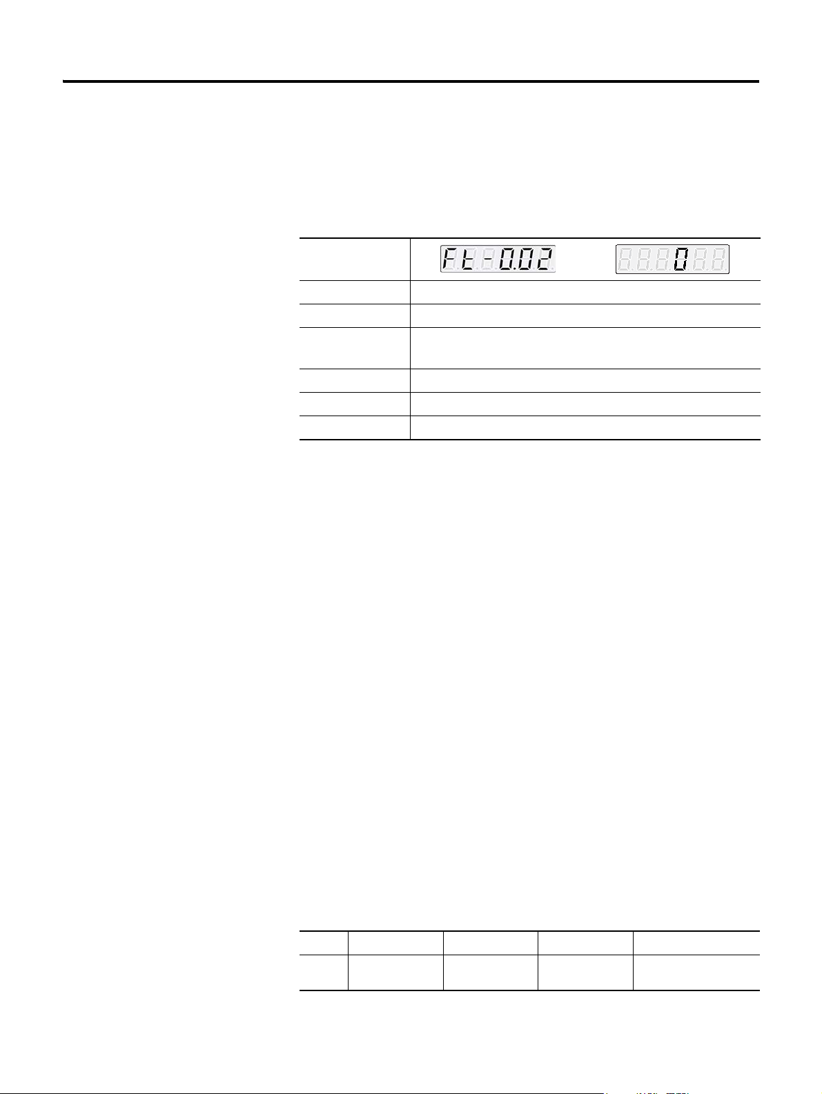
This manual uses the following table for parameter description.
Example of Parameter Setting
Parameter
Parameter Name Motor Forward Direction
Description You can choose the rotational direction of the motor
Setting Value • 0: CW
• 1: CCW
Initial Value 0
Applicable Mode All
Others Servo-OFF > Setting > End
Tab le D escr ipt ion
Parameter: at the top-left side shows the parameter being described.
The setting window on the right of the parameter, is entered when the
ENTER key is pressed. The parameter must be set from the digit in black
color and the initial value shows the initial value of the parameter.
It is classified into a parameter selected among already set values (“selected
parameter”) and a parameter, which the users give appropriate value. The
selected parameter, as shown in the example above, displays both parameter
and setting window, and the latter parameter displays only the parameter and
not eh setting window.
Parameter Name: describes the value selectable by the user and the selected
value.
Description: describes the function and usage of parameter.
Setting Value: describes the value selectable by the user and the selected
value.
Initial Value: Initial Value displayed when the parameter is selected.
Applicable Mode: alphabetically displays the corresponding control mode in
setting parameter, and displays (ALL) if all are included.
CSD5 Servo Drive
Mode Position mode Speed mode Torque mode Multi-step speed mode
DisplayFSC
P
Page 13

Preface P-3
Combinational control mode indicates the alphabets of two modes, combined
in a row.
ex) speed + position mode (SF), torque-speed mode (tS).
Others: normally, as described in an example of automobile, the driver cannot
manipulate parking brake of a running automobile, and the servo drive also
should be divided into Servo-ON status and Servo-OFF status when setting
the parameter.
Others Description
Setting > End Set regardless of the drive status.
Servo-OFF > Setting > End Set it in Servo-OFF status
Servo-OFF > Setting > Power Off &
On > End
Set it in Serve-OFF status, and apply the power
again
Terminology
The following describes terminologies used in this manual.
• Servo Drive or Drive: Refer to the CSD5 Servo Drive
• Servo Motor or Motor: Refer to the servo motor exclusively for the
CSD5 drive.
• Host Controller : Refers to a controller or a device that gives
command to the drive and controls it.
• Initial Value: Refer to the value set at the factory before the
shipment.
• Setting Value: Refers to the initial value or the value changed and set
by the users.
• User’s Manual: Simply indicated as ‘manual’.
Notation Description
Within the sentences of this manual, the following is expressed as shown
below. Be fully aware of them when using the servo drive.
1. Use ‘/’ in front of Active Low signal.
3 CSD5 Servo Drive
Page 14
P-4 Preface
I/O
HF_PULS
VCMD+
HF_PULS
VCMD-
I/O
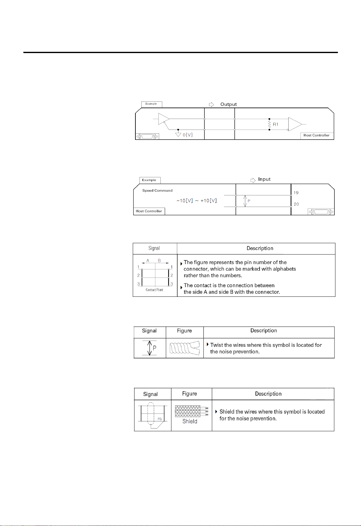
2. A figure box with both the top corners cut off diagonally represents a
circuit diagram. If I/O for I/O signal or a connector attached to the
servo driver is on the left, it is the output of I/O or servo drive.
3. If I/O for I/O signal or a connector attached to servo driver is on
the right, it is the input from the host controller to I/O or servo
drive.
4. The following shows the symbols used on the circuit
diagram.
5. The following figure shows a symbol used to show a twist pair wires
to prevent the noise generation.
6. The following figure shows a symbol used to show a shield pair wire
to prevent the noise generation.
CSD5 Servo Drive
Page 15

Preface P-5
Manual Description Order
This manual is described in the view of users from the purchase to operation.
1. Descripbes things to know before using the product.
2. Describes the outline of product and marking.
3. Describes precations upon product installation.
4. Describes wiring with the host controller and peripheral
equipment.
5. Describes the operator for various settings.
6. Describes brief functions of the product.
7. Describes the basic settings that users should set.
8. Describes the fucntion of the product for each control modes.
9. Describes the tuning to implement optimum performance of load
system.
10.Describes simple supplementary functions.
11.Describes the protective function, fault diagnosis and
troubleshooting.
12.Describes items corresponding to various numerical data in the
Appendix.
Others
Each chapter or paragraph has a page called before you begin before
description. For easier understanding of this manual, be fully aware of the
contents of this page called before you begin in advance.
5 CSD5 Servo Drive
Page 16
P-6 Preface
CAUTION
WARNING
WARNING
WARNING
Safety Precautions
This is CSD5 User Manual describes safety matters using the following marks.
Safety marks deals with the important matters. If the following marks and
contents of each mark are indicated in the contents of this user's manual, you
must be fully aware of them and follow them.
Usage
• Do not touch the inside of servo drive.
• Make sure that the servo drive and the motor are fully
grounded.
• Completely discharged before handling after power
off.
• Do not put excessive stress on the motor power and
encoder cable.
• Never touch the revolving part of the motor during
operation .
• Avoid using the product near wet places or corrosive
and inflammable materials.
• Operate the system with no load during pilot
operation.
• Never touch the heat sink directly.
CSD5 Servo Drive
Storage
• Do not store the product near wet places, rain, toxic
gas or fluid.
• Keep the product out of the direct rays of the sun and
store it within the storage temperature and humidity
ranges.
• Avoid overloading if the product is stored in a
warehouse.
Transportation
• Do not carry the product by holding the cable and the
motor shaft.
Page 17
Installation and Wiring
WARNING
CAUTION
WARNING
• Install a cooling fan to prevent excessive temperature
increase. (Refer to the Chapter 2)
• Be careful not to wiring cables around the heat sink.
• Install drives with regular space (at least 10 mm)
between them.
• Pay attention to the heat sink when wiring. (Refer to
Chapter 2)
Maintenance and Repair
• Do not disassemble or remodel the product. Any
damage caused after the user disassembles or
remodels the product will be excluded from the
company's warranty.
• The company bears no responsibility for injuries or
physical damage caused by remodeling of this
product.
• Life-limited Parts by mechanical friction or heat
requires regular . Refer to the Chapter 8.
• In case of a failure that cannot be dealt with, please
contact the company’ s technical support team or
after-sales service center.
Preface P-7
7 CSD5 Servo Drive
Page 18

P-8 Preface
CSD5 Servo Drive
Page 19
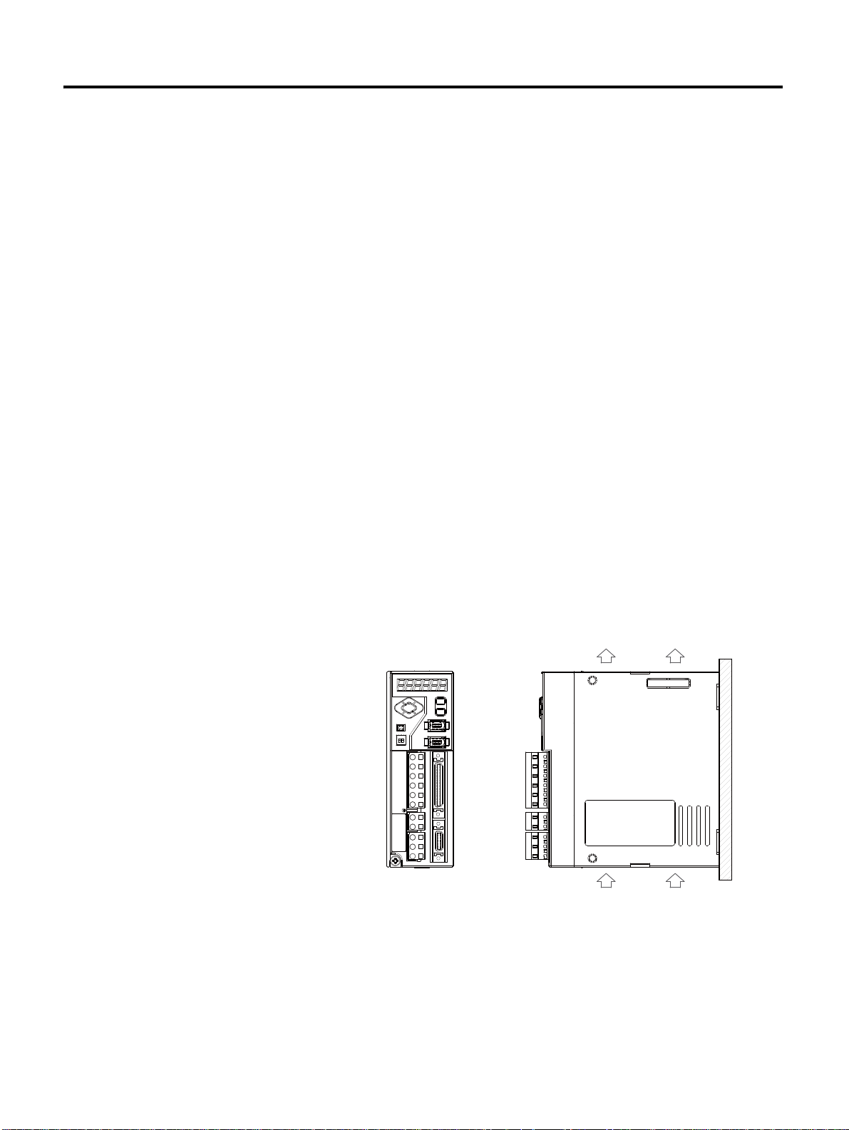
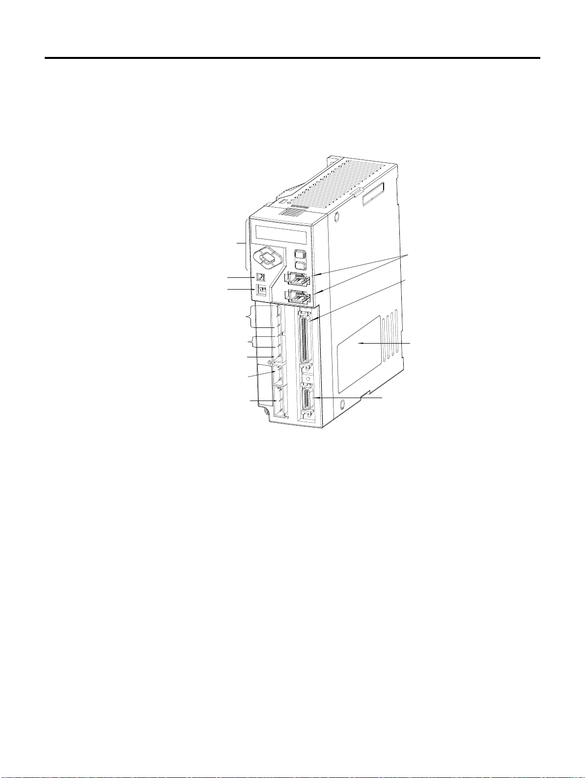
Chapter 1
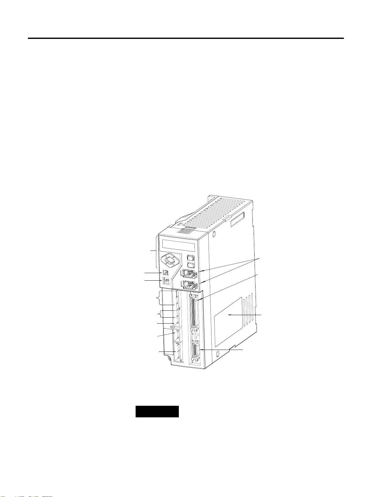
Drive Nameplate
I/O Signal Connector <I/O>
Encoder Cable Connector <Motor
Feedback>
Communication and Operator
Connector
AC Main Power Input Terminal
Control Power Input Terminal
DC Link Negative Output
Regenerative Resistor Terminal
Motor Cable Terminal
Operator
Analog Output Terminal
Terminating Resistance Setting
TIP
Before Using the CSD5 Servo Drive
This chapter describes the general matters and optional specifications that you
should know before using the CSD5 SERVO DRIVE.
Product Type and Each
Part Name
The following figure introduces the name of each part of the servo drive.
1 CSD5 Servo Drive
For more detail information about Operator, please refer to
“ Chapter 4 Operator, Basic Setting and Startup”.
Page 20
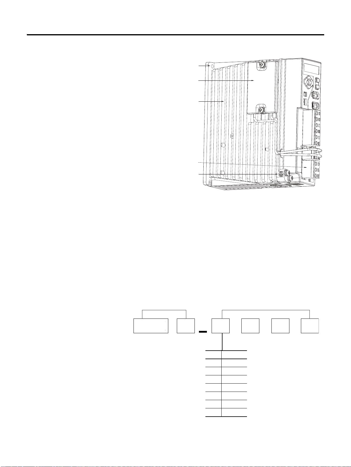
1-2 Before Using the CSD5 Servo Drive
Mounting Hall (Top, Bottom)
Regenerative Resistor
(400 [W] or Higher Attached)
Heat Sink
Wiring Socket (6P, 2P, 3P) 3 PART
Ground T e rminal (Heat Sink)
Drive Type Example of Servo Drvicve Specification
Mask Rated
A5 50 [W]
01 100 [W]
02 200 [W]
04 400 [W]
08 800 [W]
10 1 [kW]
15 1.5 [kW]
CSD
5
A5
BX1
Model Number of the
The following figure describes the model name on the nameplate of the servo
drive.
Drive
• The nameplate is attached on the side of the drive case. Check the
model name on the nameplate, and check if it corresponds to the
product ordered.
• The drive type is RS Automation Servo Drive CSD5 Series.
• The serial number is included on the nameplate. Be careful not to erase
the serial number during the use.
KNX 3 - K A P 0
CSD5 Servo Drive
Page 21
Before Using the CSD5 Servo Drive 1-3
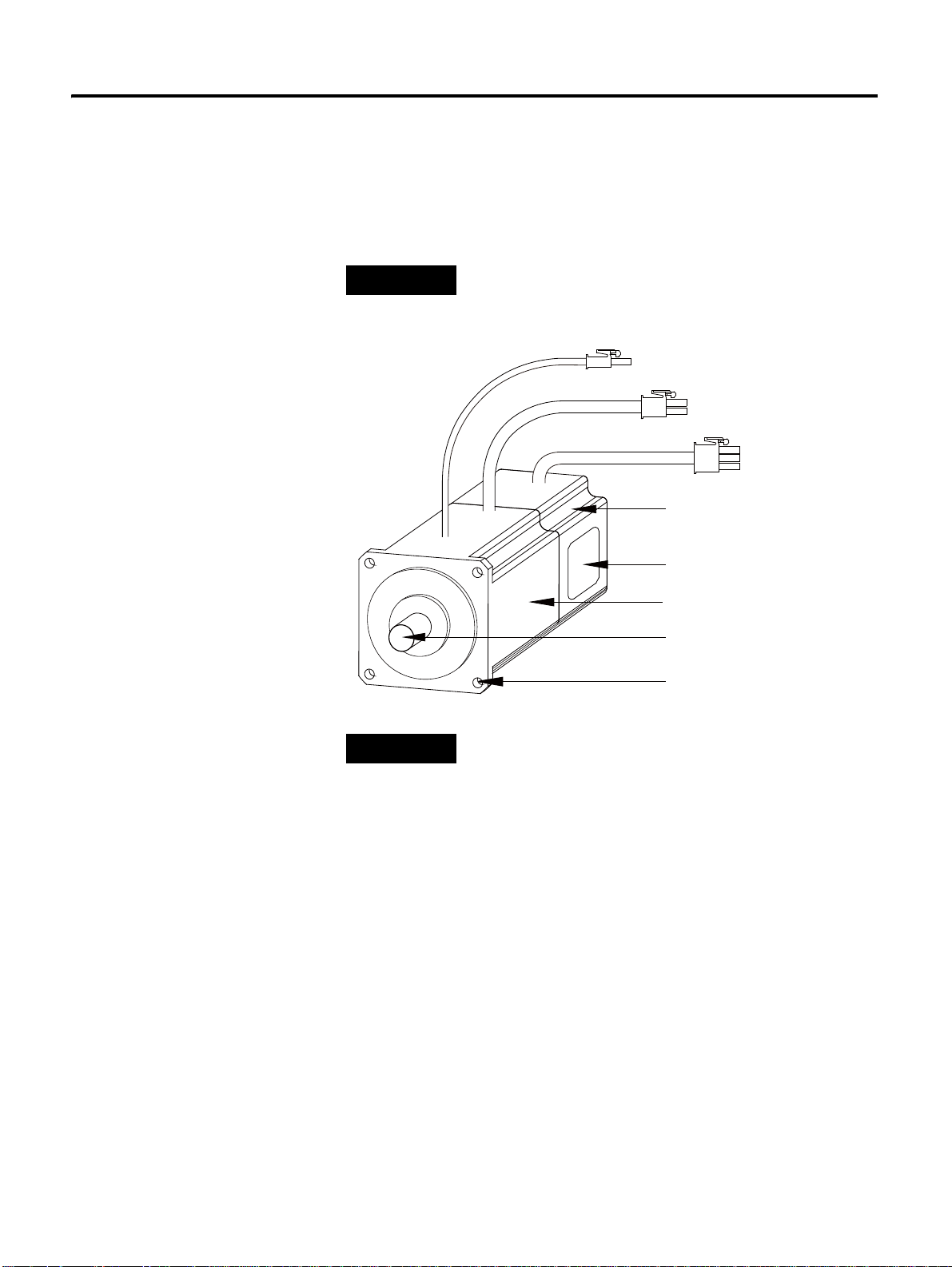
TIP
Break Cable
Motor Cable
Encoder Cable
Encoder
Motor Nameplate
Motor Frame
Motor Shaft
Mounting Hole
TIP
Name of Each Motor Part
The following figure shows the name of each more part.
A motor without a brake does not have a brake cable. The name of each motor
part may differ from the following figure according to the motor type.
For more detailed infroamtion about Servo Motor, please
refer to “ Servo Motor Manual” .
RS Automation does not provide cables. For more
information about specification and order code of cables
below, refer to "Servo Motor Manual (Publication
SMOTOR-UM002)".
• Motor 3 phase Power Cable
• Encoder Cable
• Motor Break Cable
• I/O Cable
• Communication Cable
3 CSD5 Servo Drive
Page 22

1-4 Before Using the CSD5 Servo Drive
C S M T - 0 1 B B 1 A N T 3
Motor Type Example of Motor Specifcation
Rated Output
Voltage
Encoder Type
Design Sequence
Motor Axis Key
Option
Manufacturer
Shaft Specification
TIP
Model Number of the
Motor
The following figure describes the model name of the motor on the
nameplate.
For more detailed information about each motor name
plate items, refer to Servo Motor Manual.
CSD5 Servo Drive
Page 23
Chapter 2
Natural
Natural
Installation
This chapter describes matters to consider when installing the servo drive and
the motor. Refer to the appendix for numerical data on the drive, motor, and
various peripheral equipments necessary for the installation.
Servo Drive Installation
Precautions
Refer to the following figures when installing the servo drive.
The most important thing to consider when installing the drive is the ambient
temperature. Follow the operational temperature and mount the servo drive
vertically.
Install the Servo Drive Vertically
Servo drive less than 400 [W] applies the natural convective cooling, and the
servo drive with more than 0.8 [kW] uses the cooling fan. To increase the
cooling efficiency, install it vertically.
1 CSD5 Servo Drive
Page 24
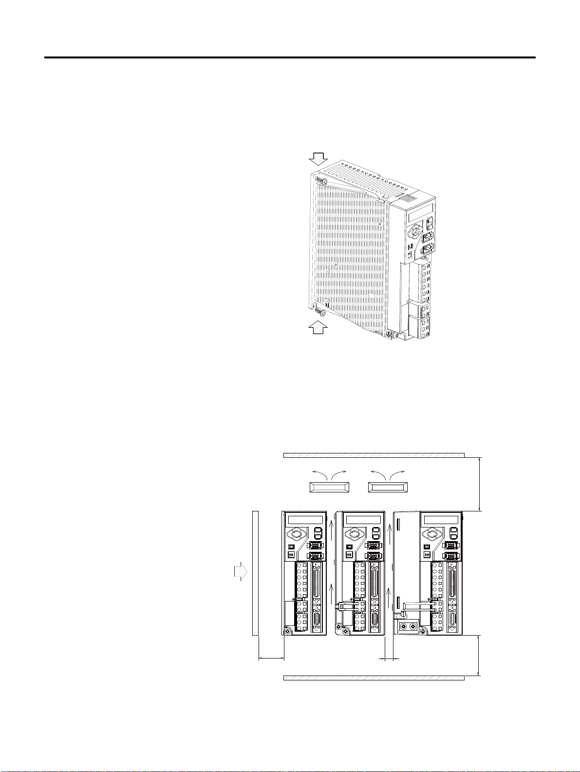
2-2 Installation
Fixing Bolt
Fixing Bolt
Cooling Fan
Cooling Fan
Panel
More than
50 [mm]
More than
50 [mm]
More than 10
More than 30 [mm]
Fixing Bolt
• 400 [W] or less: M4xL1 0 mounting holes at the top & bottom
• 0.8 [kW] or more: M5xL10 mounting holes at the top & bottom
Use A Cooling Fan When Installing Several Drives.
When installing several drives, you must the following criteria. Install a cooling
fan to prevent excessive temperature increase.If the surrounding temperature
is higher than the operational temperature, it may reduce the performance.
CSD5 Servo Drive
Page 25
Installation 2-3
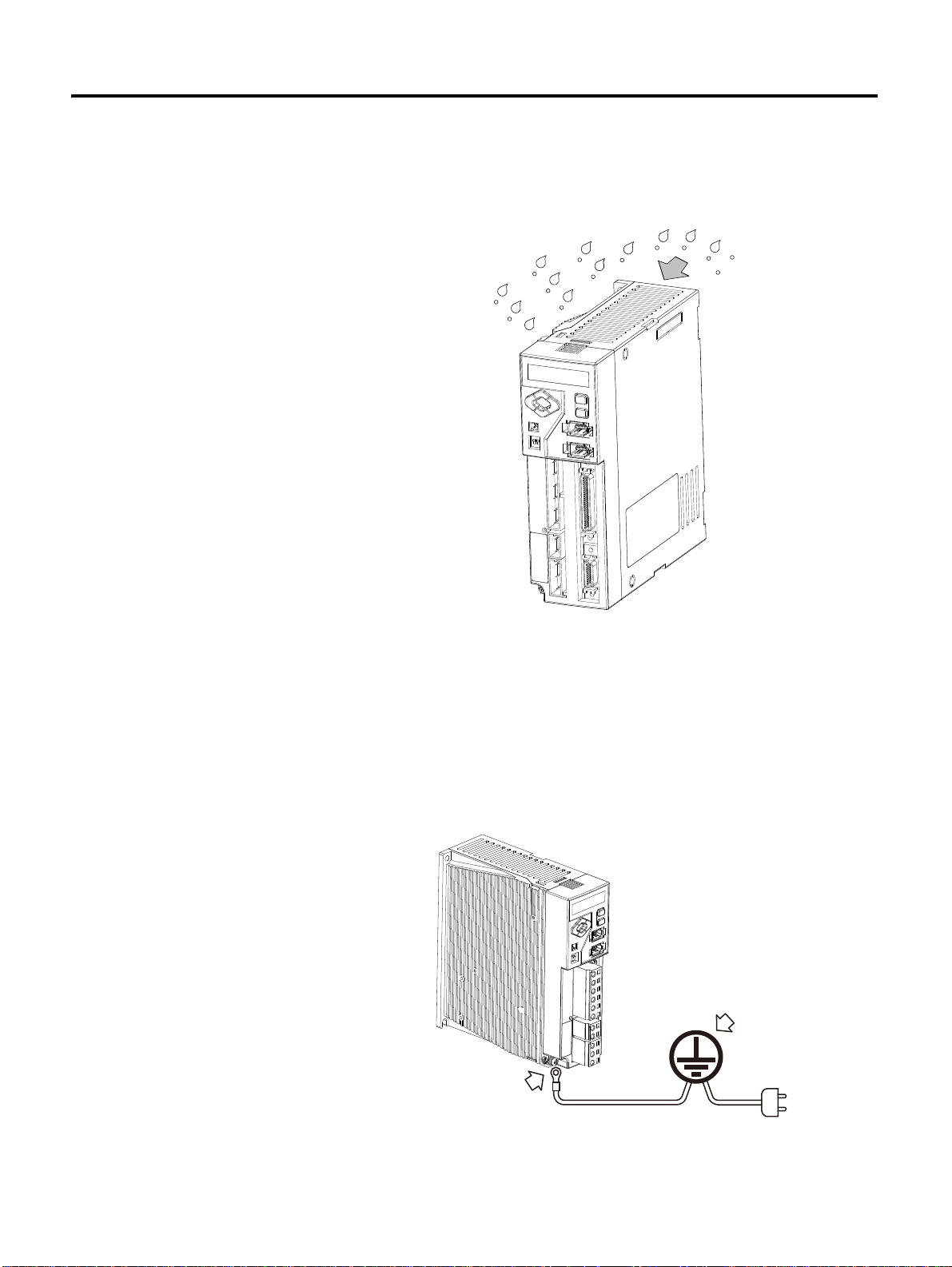
Use the Drive in a Clean Environment
Use the drive in a clean environment where there is no dust or humidity.
Ground
There is a grounding terminal at the bottom of the heat sink.
• 200 [W] or less: 1 mounting hole for M4 BOLT
• 400 [W] or above: 2 mounting holes for M4 BOLT
If not grounded, it may reduce the performance.
3 CSD5 Servo Drive
Page 26

2-4 Installation
IMPORTANT
TIP
Installation Environment
CSD5 Servo Drive installation environment is like below.
Table 2.1 CSD5 Servo Drive Installation Environment
Item Installation Environment
Storing Temperature
Store it within -25 ~ 85 [
℃]
Operational
Temperature
Operational
Humidity
Vibration 5-55Hz @ 0.35mm(0.014") double amplitude, continuous
Operational Location Installation environment must meet the follwoing conditions:
Use it within 0 ~ 50 [
Use it below 5 ~ 95 [%] RH at a place without condensations
displacement, 55-500Hz @ 2g peak constant acceleration
• Indoors
• Well ventilation
• Easy checkup
• Without explosive gas
℃]
• To maintain reliability for a long time, use it within to
0~35 [℃].
• Install a separate cooling device at a place with high
ambient temperature and use it within the operational
temperature.
Servo Motor Installation
CSD5 Servo Drive
For numerical data related to the installation of the servo
motor, please refer to Servo Motor User Manual.
Page 27
Chapter 3
CAUTION
Wiring
This chapter describes the information on motor, host controller and
other wiring connected to the servo drive, along with the circuit
diagram.
Before You Begin
Pay attention to the following precautions when wiring.
• Wiring should be done only by the qualified personal.
• High voltage remains in the drive even through the
power is off. Therefore, do not inspect components
unless inside Charge lamp is off.
• Pay attention to the polarity when wiring.
• The heat sink of the drive generates high heat. Pay
attention to the heat sink when wiring.
1 CSD5 Servo Drive
Page 28
3-2 Wiring
Drive Nameplate
I/O Signal Connector <I/O>
Encoder Cable Connector
<Motor Feedback>
Communication and Operator
Connector
AC Main Power Input Terminal
Contor Power Input Terminal
DC Link Negative Output
Regenerative Resistor Terminal
Motor Cable Terminal
Operator
Analog Output Terminal
RS485 Terminating Resistance Setting
In this chapter, the circuit is divided into electric circuit and signal
circuit for easier and convenient explanation. Be fully aware of the
names of each terminal when reading this user’s manual.
Electric Circuit
CSD5 Servo Drive
The I/O signal connector I/O and encoder cable connector Motor
Feedback are included only in the description of the signal circuit. The
description of other connectors and omitted.
Name and Function
The terminal symbol is printed on the wiring socket at the electric
circuit terminal of the drive. Observe the drive to identify and
understand the terminals on the following table, and then wire
accordingly.
Page 29
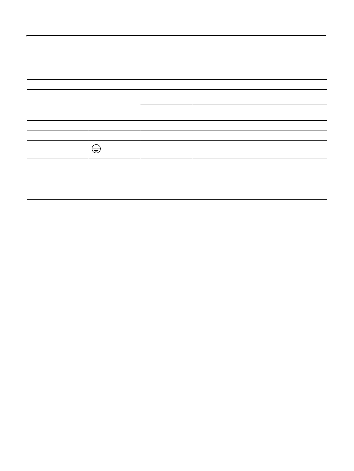
Table 3.1 Electric Circuit
Terminal Terminal Symbol Purpose
Wiring 3-3
AC Power Terminal L1, L2, L3 400 [W] or lower Single phase 200 ~ 240 [V] (50/60 [Hz]) (L3 port must not
800 [W] or higher 3 phase 200 ~ 240 [V] (50/60 [Hz]) (800 [W] can be used as
Control Power Te rminal L1C, L2C No output division Single phase 200 ~ 240 [V] (50/60 [Hz])
Motor Cable T e rminal U, V, W Connect the motor cable.
Grounding Terminal
(Heat Sink)
Regenerative Register
Connection Port
B1, B2 200 [W] or lower As the function for regenerative energy consumption is not
Connect the power and motor cable to the grounding terminal.
400 [W] or higher If the capacity of mounted regenerative resistor is
be used)
Single phase )
required, the regenerative resistor does not have to be
mounted.
insufficient, remove it or connect it to the mounted
regenerative resistor in parallel.
AC Power Terminal (L1, L2, L3) and Control Power Terminal
(L1C, L2C)
The main power and control power can be divided when connecting to
the drive. Therefore, the user can configure surrounding circuits when
the main power is cut off in an emergency or when the drive itself
checks the status and cuts off the power.
If the drive independently checks the status and only the main power is
cut off, but not the control power, the drive can display the cause of
cut-off of the main power. The user can take appropriate action after
identifying the cause of cut-off of the main power.
Refer to the 3-5 page "Electric Circuit Diagram"for the Electric Circuit
Diagram of the power separation.
3 CSD5 Servo Drive
Page 30
3-4 Wiring
WARNING
CAUTION
Motor Cable Connectors (U, V, W)
The motor cable connectors (U, V, W) are output terminals.
Do not connect the input power. It may cause of the drive
damage.
Regenerative Register Connection Port
Refer to the 7-12 page "Reneration Resister" for more information the
Regeneration Resistor.
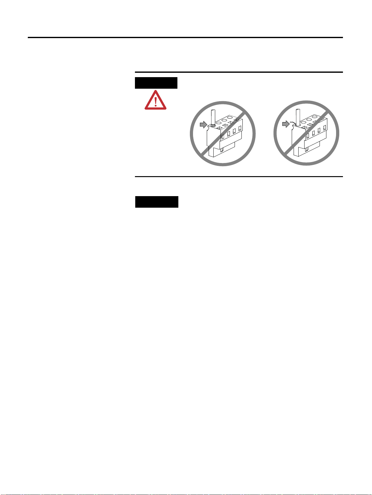
• When wiring the wiring socket, be careful not to expose
the core wire. It may cause an electric shock.
• Completely discharged before handling after power off.
CSD5 Servo Drive
Page 31

Electric Circuit Diagram
Lamp
Relay 1
L1C
L2C
L1
L2
N
L3
1MC
NOISE
FILTER
SW 1 OFF
SW 2 ON
Relay 1
<1>
1 MCCB
1MC
<3>
SUP
<2>
1MC
SERVO DRIVE
B2
B1
<Shield >
CN 2
V
U
W
PG
M
1/2
45
46
Relay 1
CN 1
SALM +
SALM -
24V
+ 24V IN
Power
MCCB (Molded Case Circuit Breaker)
MC (Magnetic Contactor)
<1> For more than one second, press the
Push Button S/W which allows the
current to flow when pressed.
<2> Connect this if the power needs to be
cut-off.
<3> Attach a surge suppressor to the MC
relay coil.
Alarm
Do not connect this to the
drive with less than 400 [W].
Connect this to the
grounding terminal of the
Regenerative
Resistor
Heat Sink
Servo Motor
I/O
Motor Feedback
DC-
CAUTION
Wiring 3-5
Use single-phase power in servo drive whose rated output
(capacity) is 400 [W] or lower. Thus, do not use the
5 CSD5 Servo Drive
terminal L3.
Page 32

3-6 Wiring
+
Prepare the Wires Strip of the
Phenol Terminial
Assemble the Socket
Wire
Terminal
Comress with the Phenol
Terminal Compressor
Socke
Lever
NOTE: Keep the length of the peeled wire less than 8
Using the Socket and Lever
This section describes the usage of wiring socket and lever provided
with servo drive.
• Connect only one wire at wire inlet of the socket.
• If the wire is pulled accidentally with an excessive force, rewire it
properly.
• The peeled wire can be used. (Keep the length of the peeled core wire
less than 8 [mm].)
• The use of phenol terminal is recommended for the reliability of wiring.
• Use a lever for wires provided with the product.
The following figure shows the sequence of assembling wire at the
socket.
1. As shown in the figure, insert lever in the socket and press it.
2. Insert wire into socket and release the lever.
3. Pull it slightly to check if the connection between the socket and wire is
normal.
The thickness of wire allowed by the socket is shown below.
Thickness of Wire
Twist AWG20 ~ AWG14
CSD5 Servo Drive
Page 33
Wiring 3-7
CAUTION
NOTE
Insert the wire completely. If peeled core wire is exposed, it
may cause an electric shock.
The lever is a small tool, used when wiring. Keep it for
other wiring jobs.
7 CSD5 Servo Drive
Page 34
3-8 Wiring
I/O Signal (I/O)
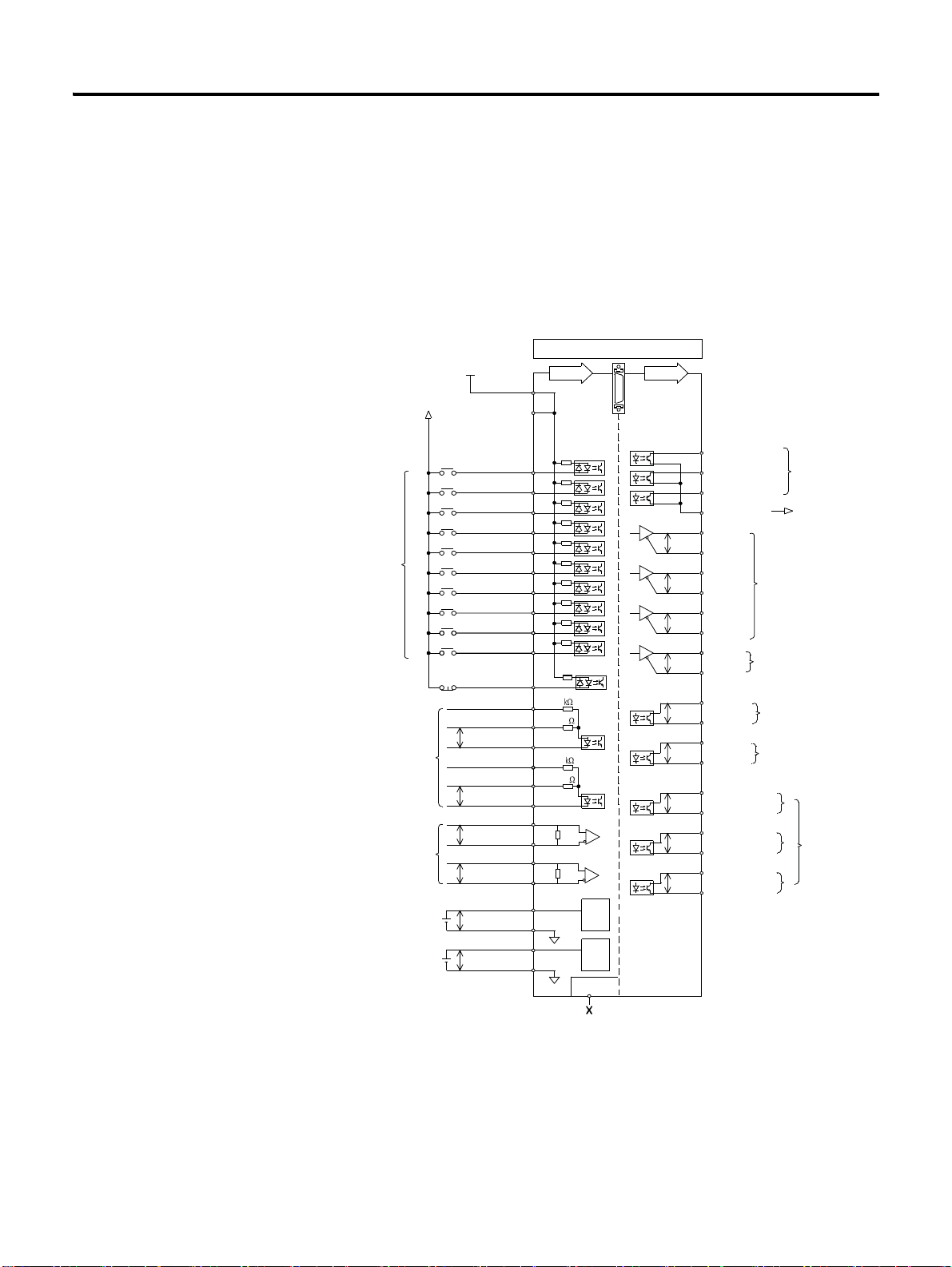
I/O Connection Diagram
This is the circuit diagram of a connector for I/O signal. It is divided
into input on the left and output on the right.
The Backup battery for absolute value encoder does not have the
separate terminal. It must be connected to motor encoder cable.
CN1
I/O
24V
Active Low/High
Programmable
Digital Inputs
Position
Command
High Frequency
Position
Command
Speed Command
-10V to +10V
Current Command
-10V to +10V
GND [or 24V]
24V [or GND]
INPUT1 (/SV-ON)
INPUT2 (P-OT)
INPUT3 (N-OT)
INPUT4 (/P-CON)
INPUT5 (/A-RST)
INPUT6 (/N-TL)
INPUT7 (/P-TL)
INPUT8
INPUT9
INPUT10
E-STOP
24V_PULS+
PULS +
PULS -
24V_SIGN+
SIGN +
SIGN -
HF_PULS +
HF_PULS -
HF_SIGN +
HF_SIGN -
(1)
(1)
INPUT
1
2
(1)
3
4
5
(1)
6
(1)
7
(1)
8
(1)
9
26
27
28
10
2
49
150
11
12
2
25
150
13
14
15
16
23
24
19
20
21
22
16-bit
A/D
12-bit
A/D
50
OUTPUT
37
38
39
40
29
P
30
31
P
32
33
P
34
35
P
36
17
P
18
45
P
46
41
P
42
43
P
44
47
P
48
FAULT 1 / OUTPUT 4
FAULT 2 / OUTPUT 5
FAULT 3 / OUTPUT 6
FCOM/OUTCOM
AM +
AM -
BM +
BM -
IM +
IM -
PS +
PS -
Z-PULSE +
Z-PULSE -
FAULT +
FAULT -
OUTPUT1+ (P_COM+)
OUTPUT1- (P_COM-)
OUTPUT2+ (TG_ON+)
OUTPUT2- (TG_ON-)
OUTPUT3+ (BK+)
OUTPUT3- (BK-)
Binary Fault Code Outputs
/ Digital Outputs
Binary Fault Code Ground
/ Digital Outputs Ground
Buffered
Encoder
Output
Absolute Position
Serial Output
Encoder
Marker
Pulse
Fault
Output
24V
Programmable
Digital
Outputs
CSD5 Servo Drive
(1) Factory Default Value
Page 35

Wiring 3-9
Table 3.2 (I/O) Pin Arrangement for host controller connections
Pin Symbol Description Pin Symbol Description
1 +24V IN External 24 [V] input for contact point
input
2 +24V IN External 24 [V] input for contact point
input
3 INPUT1
4 INPUT2
5 INPUT3
6 INPUT4
7 INPUT5
8 INPUT6
9 INPUT7
Digital input 1(/SV-ON)
Digital input 2(P-OT)
Digital input 3(N-OT)
Digital input 4(/P-CON)
Digital input 5(/A-RST)
Digital input 6(/N-TL)
Digital input 7(/P-TL)
(1)
(1)
(1)
(1)
(1)
(1)
(1)
10 ESTOP ESTOP(Default:Disable) 35 PS+ Absolute Encoder Position data output+
11 PULS+ Position command pulse input+ 36 PS- Absolute Encoder Position data output12 PULS- Position command pulse input- 37 FAULT1/
13 SIGN+ Position command sign input+ 38 FAULT2/
14 SIGN- Position command sign input- 39 FAULT3/
15 HF_PULS+ High frequency position command
pulse input+
16 HF_PULS- High frequency position command
pulse input-
17 Z-PULSE+ Encoder Z-pulse output (Open
collector)
18 Z-PULSE- Encoder Z-pulse output (Open
collector)
19 VCMD+ Speed command input+ 44 OUTPUT220 VCMD- Speed command input- 45 FAULT+ Alarm generation signal output+
21 ICMD+ Current command input+ 46 FAULT- Alarm generation signal output22 ICMD- Current command input- 47 OUTPUT3+
23 HF_SIGN+ High speed position command sign
input+
24 HF_SIGN- High speed position command sign
input-
25 24V_SIGN+ Open collector sign input + for 24 [V]
level
(1)
Factory default values
26 INPUT8 Digital input 8
27 INPUT9 Digital input 9
28 INPUT10 Digital input 10
29 AM+ Encoder signal output A+
30 AM- Encoder signal output A31 BM+ Encoder signal output B+
32 BM- Encoder signal output B33 IM+ Encoder signal output Z+
34 IM- Encoder signal output Z-
Alarm code output 1/Digital output 4
OUTPUT4
Alarm code output 2/Digital output 5
OUTPUT5
Alarm code output 3/Digital output 6
OUTPUT6
40 FCOM/
Alarm code/ Output ground
OUTCOM
41 OUTPUT1+
42 OUTPUT1-
43 OUTPUT2+
48 OUTPUT3-
Digital output 1 +(P_COM+)
Digital output 1 -(P_COM-)
Digital output 2 +(TG_ON+)
Digital output 2 -(TG_ON-)
Digital output 3 +(BK+)
Digital output 3 -(BK-)
(1)
(1)
(1)
(1)
(1)
(1)
49 24V_PULS+ Open collector pulse input + for 24 [V]
level
50 NC Not Available
9 CSD5 Servo Drive
Page 36

3-10 Wiring
(I/O) Input Signal
Sequence Input Signal (Allocation)
Refer to the 5-1 page "Sequence I/O (Input/Output) Signal" for details
of sequence input signal.
Table 3.3 I/O Sequence Input Signal
Type Description Mode Reference
</SV-ON> Servo-ON When the servo is set to ON, voltage is applied to the servo
</A-RST> Alarm Reset It disables the Servo's Alarm. All
</G-SEL> Gain Group
Conversion
</P-CL> Forward Torque
Limit
</N-CL> Reverse Torque
Limit
<P-OT> Prohibit Forward
Rotation
<N-OT> Prohibit Reverse
Rotation
</P-CON> P Control
Conversion
</C-SEL> Control Mode
Conversion
</C-DIR>
</C-SP1>
</C-SP2>
</C-SP3>
</C-SP4>
Contact Speed Command
</Z-CLP> Zero Clamp Ignores the input value in the Speed Control when the
</INHIB> Inhibit Pulse
Command
</ABS-DT> Absolute
Encoder Data Transmission
</PCLR>Position Error Clear Clears position command, position feedback, and position
</ST ART>Start Set to start or stop the motor rotation by using the contact
</GEAR>Electronic Gear
Rate Shift
</R-ABS>Absolute Encoder
Multi-rotation Data Reset
motor; when it is set to OFF, voltage is cut off.
Use 2-group gain where it is set to ON and use current gain
where it is set to OFF. It converts gain of 2 groups.
When it is set to ON, limit the forward torque by the set value
[Ft-4.03].
When it is set to ON, limit the reverse torque by the set value
[Ft-4.04].
It prohibits the motor from rotating forward when the load
device reaches the limit of the available sect ion.
It prohibits the motor from rotating reversely when the load
device reaches the limit of the available sect ion.
It converts the Seed Controller from PI type controller to P
type controller. It is used to suppress the overshoot of the
excessive response and complete a faster response.
It is used to convert Control Mode when using it as
Combination Control Mode.
At the Contact Speed Control Mode, these input combinations
decide the rotation direction of the motor </C-DIR> and the
rotation speed </C-SP1 ~ /C-SP4>. The rotation speed for </
C-SP1~/C-SP3> input is set in [Ft-2.05~Ft-2.11]. The
analogue speed command voltage decides the rotation speed
for </C-SP4>. </C-DIR> is used to change the motor rotation
direction in Speed Control Mode.
command value is lower than the value set in the Speed Zero
Clamp Level [Ft-5.05].
Inhibits the position command pulse where it is ON. F
When it is set to ON, transmits the absolute encoder data to a
higher level through AM, BM signals.
error.
signal in Speed/Contact Speed Control Mode.
In the Position Control Mode, use the 2nd electronic gear
parameter [<:fc 2>Ft<:/fc>-3.05]and [Ft-3.06] where it is ON,
use the basic electronic gear parameter [Ft-3.01]and [Ft-3.02]
where it is OFF. It shifts between two electronic gear ratios.
Reset the multi-rotation data of the absolute motor. All
All
All
All
All
All
All
F, S, P, I
Combinational
Control Mode
Only
P
S
F, I
F, I
S, P
F
4-1 page
7-49 page
6-36 page
5-46 page
5-46 page
7-2 page
7-2 page
6-30 page
5-57 page
5-51 page
5-35 page
5-25 page
7-50 page
5-25 page
5-37 page
5-27 page
7-34 pag
e
CSD5 Servo Drive
Page 37

Wiring 3-11
Table 3.3 I/O Sequence Input Signal
Type Description Mode Reference
</BANK_SEL>Gain Bank
Select
</A-CL>Analog Torque Limit Current Limit Function is activated by the analogue torque
</H_SENS>Home Sensor When activated, the sensor indicates the Return to Home
</SHOME>Start Homing When activated, the system starts returning to home. I .
</PAUSE>Index Pause When activated, it decelerates until stop and pause the index
</STOP>Index Stop When activated, index movement ends. I .
</I-SEL0>
Index Selection 0 Input
</I-SEL1>
Index Selection 1 Input
</I-SEL2>
Index Selection 2 Input
</I-SEL3>
Index Selection 3 Input
</I-SEL4>
Index Selection 4 Input
</I-SEL5>
Index Selection 5 Input
</H_STOP>Homing Stop Stops Homing operation when it is set to ON. I
</START_I>Start Indexing Starts Indexing when it is set to ON. I
</ABS-MD> Absolute
Position Data Transfer Mode
Uses the 3rd and the 4th Gain Bank when it is set to ON. All
command input values when it is set to ON.
sequence that is detected.
sequence. It decides whether to stop or to continue the motion
by constantly monitoring the input status.
Used for the combinations to allocate indexes. I .
Absolute Data transfered to host contoller by photo coupler
output which output Fault Code when it is set to ON.
S, P
I
I.
F
6-38 page
General Input Signal (Fixed)
Power
Table 3.4 Power Input Signal
Signal Name Symbol Function Mode Reference
External power
input
11 CSD5 Servo Drive
+24V IN As control power input for contact point signal, +24 [V]
power should be prepared by users.
Power Specifications: 21.6 ~ 26.4V, 210mA
All
Page 38

3-12 Wiring
Emergency Stop
Table 3.5 Emergency Stop Input Signal
Signal Name Symbol Function Mode Reference
Emergency Stop E-STOP Connect and use an extra emergency stop switch to
quickly act upon emergency situation, users can select
whether to use in [Ft-0.05] constant.
All 3-18 page
Position Command
Table 3.6 Position command input signal
Signal Name Symbol Function Mode Reference
Pulse Command PULS+ Receives position command by pulse input. Can
PULSSIGN+
SIGN-
High Frequency
Pulse Command
Open Collector(24
[V]) Pulse
Command
Speed Command
Input
Torqu e Command
Input
HF_PULSE+ Connect the high frequency pulse input to this terminal.
HF_PULSEHF_SIGN+
HF_SIGN24V_PULSE+ For Open Collector 24 [V] pulse input, connect to this
PULS24V_SIGN+
SIGNVCMD+ Receives analog speed command.
VCMDICMD+ Receives analog torque command.
ICMD-
respond to line drive or 12 [V] & 5 [V] open collector
output of the host controller.
(Line Drive less than 3 [Mpps])
terminal without a pull-up resistance.
(-10 [V] ~ +10 [V])
(-10 [V] ~ +10 [V])
F
F
F
S
C
5-10 page
5-32 page
5-43 page
CSD5 Servo Drive
Page 39

Wiring 3-13
(I/O) Output Signal
Sequence Output Signal (Allocation)
Refer to the 5-1 page "Sequence I/O (Input/Output) Signal" for details
of sequence output signal.
Table 3.7 I/O Sequence Output Signal
Signal Name Description Mode Reference
</S_ALM> Alarm Outputs when Servo Alarm sets off. All
</P-COM (+, -)> Position
Completion Detection
</NEAR (+, -)> Position
Proximity Detection
</V-COM (+, -)> Speed
Match Detection
</TG-ON (+, -)> Rotation
Detection
</T -LMT (+, -)> T orque Limit
Detection
</V-LMT (+, -)> Speed Limit
Detection
<BK (+, -)> Brake Control It is the signal for the brake control installed inside or outside
</A-VLD> Absolute Position
Valid
</RDY> Drive Ready Means getting the operation ready while in the Servo-OFF
</WARN (+, -)> Warning Turns to ON when a Servo warning is detected. All
</HOMC (+,-)> Axis Homing When activated, it shows the completion of the Homing
</IMO (+,-)> In Motion Turns to ON when in motion. I .
</I-DW> In Dwell When activated, it indicates that the motor is on the hold
</O_ISEL0>
Index Selection 0 Input
</O_ISEL1>
Index Selection 1 Input
</O_ISEL2>
Index Selection 2 Input
</O_ISEL3>
Index Selection 3 Input
</O_ISEL4>
Index Selection 4 Input
</O_ISEL5>
Index Selection 5 Input
</E_SEQU> Sequence
Operation Completion
Turns to ON, when the position err or is with in th e set val ue of
the position completion range [Ft-5.00].
Turns to ON, when the position err or is with in th e set val ue of
the position completion range [Ft-5.02].
Turns to ON when the deviation between the speed command
and the motor rotation speed is within the set value of the
speed match decision range [Ft-5.03].
Turns to ON when the motor is rotating above the set value of
the rotation detection level [Ft-5.04].
Turns to ON when torque reaches the set value of the torque
limit.
Turns to ON when speed reaches the set value of the speed
limit.
of the servo motor.
Turns to ON when the absolute position data is valid while
using the absolute motor.
status.
operation.
position in the index movement and on stand-by for the dwell
time assigned.
Used to output the index number in use in the selected
indexing operation.
Turns to ON when the index movement is complete. I
F, I
F, I
F, S, P, I
All
All
All
All
All
All
I.
I.
I.
8-5 page
5-28 page
5-28 page
5-38 page
5-39 page
5-46 page
5-41 page
7-6 page
8-3 page
13 CSD5 Servo Drive
Page 40

3-14 Wiring
NOTE
NOTE
In this manual, < > is applied to the names of sequence I/
O signal. ex) </SV-ON>, </P-COM>
General Output Signal (Fixed)
Alarm Code
Table 3.8 Alarm Code Output Signal
Signal Name Symbol Function Mode Reference
Alarm code FAULT1/OUTPUT4
(Alarm 1/Digital
output 4)
Upon servo alarm generation, it outputs the
types of the servo alarm with the 3-bit.
Maximum rating of open collector: DC 30 [V],
20 [mA]
All
8-3 page
If one or more of Alarm code (FAULT1, 2, and 3) set to
Digital output, Alarm code does not output.
Encoder Signal
Table 3.9 Encoder Signal
Signal Name Symbol Function Mode Reference
Encoder Signal
Output
Absolute Encoder
Position S pulse
AM+ Displays multiplied encoder signal A, B, C pulse in the
AMBM+
BMIM+
IMPS+ Outputs the number of rotation by serial data when the
PS-
form of line drive. According to the parameter setting,
the drive can logically invert output of A, B pulse.
absolute encoder is used.
All
All
7-24 page
7-24 page
Servo Alarm
Table 3.10 Servo Alarm Output Signal
Signal Name Symbol Function Mode Reference
Servo alarm
Monitor Output
CSD5 Servo Drive
FAULT+ It is displayed if the servo alarm is generated. All
FAULT-
7-28 page
Page 41

Wiring 3-15
Encoder Z-pulse Display
Table 3.11 Encoder Z-pulse Output Signal
Signal Name Symbol Function Mode Reference
Encoder Z-pulse Z-PULSE + It is displayed if Z-Pulse of the encoder is detected. All
Z-PULSE -
15 CSD5 Servo Drive
Page 42

3-16 Wiring
Line Drive
SN75174
Host
P
150 [Ω]1 [kΩ ]
2.8 [V] ≤ (H Level) - (L Level) ≤
I/O
Open Collector
Host Controller
P
2 1
VF = 1.5 ~ 1.8
I/O
Vcc
TR1
VF
i
NOTE
(I/O) Input Circuit and
Interface
Describes the connection circuit for input from the host controller to
the servo drive.
Pulse Command Input Circuit
The drive receives the pulse output of host controller by position
command in position control mode.
Host controller can output pulse in line drive or open collector type.
Refer to the 5-10 page "Position Control Mode" for the servo drive
setting according to the selection.
Line drive - Maximum allowable frequency 900 [kpps](Duty ratio: 50:50)
– Input pin number
• PULS+ (11), PULS- (12)
• SIGN+ (13), SIGN- (14)
CSD5 Servo Drive
Open Collector (24 [V])- Maximum Allowable Frequency 250 [kpps]
– Input pin number
• 24V : PULS+ (49) , PULS- (12)
• 24V : SIGN+ (25), SIGN- (14)
For Open Collector 24 [V] input, it does not need the
external resistance.
High Frequency Line Drive - Maximum Allowable Frequency 3 [Mpps]
– Input pin number
Page 43

• PULS+ (15), PULS- (16)
Line Drive
SN75174
Host
P
I/O
NOTE
Analog Input Circuit
390 [Ω] (1/2
Host
P
I/O
Speed
12 [V] 2
1000:1
VCMD+
VCMD-
0 [V]
+
A/D
• SIGN+ (23), SIGN- (24)
Maximum allowable frequency of host controller’s pulse
command is
• 900 [kpps] for the line drive
• 3 [Mpps] for high speed line drive
• 250 [kpps] for the open collector
If the maximum allowable frequency is exceeded,
[E.PoSEr] servo alarm of position command pulse is
generated. Make sure the output of host controller does not
exceed the maximum allowable frequency.
Wiring 3-17
17 CSD5 Servo Drive
Analog Voltage Input Circuit
The drive receives analog voltage output of the host controller with
speed, speed of torque control mode and torque command.
Input impedance of speed and torque commands is about 10 [kΩ].
Maximum allowable voltage range of input signal is -10 [V] to +10 [V].
Input pin of I/O that uses analog voltage output of the host controller:
• Speed Command: VCMD+ (19), VCMD- (20)
• Torque Command: ICMD+ (21), ICMD- (22)
Page 44

3-18 Wiring
Analog Input Circuit
390 [Ω] (1/2
Host
P
I/O
Torque
12 [V] 2
1000:1
ICMD+
ICMD-
0 [V]
+
A/D
Relay Circuit
DC 24 [V] 50 [mA] or
Host
P
+24 [V]
3.3 [kΩ]
Sequence Input
Signal
I/O
i
Open Colletor Circuit
DC 24 [V] 50 [mA] or
Host
P
+24 [V]
3.3 [kΩ]
Sequence Input
Signal
I/O
i
Sequence Input Circuit
Relay or open collector output of the host controller is used for the
sequence input circuit.
Make sure that the input current i is within 7 [mA] to 15 [mA].
CSD5 Servo Drive
Emergency Stop Signal
This drive has a built-in circuit for the emergency stop situation.
To quickly respond to the equipment failure or dangerous situation, it
receives the emergency stop signal from #10 pin of I/O.
Emergency stop input can be done by the relay contact output of host
controller and installing a separate switch.
Page 45

Wiring 3-19
Normal
E-STOP Switch
Install a host
Controller or a
+24 [V]
I/O
External Power 24 [V]
1/2
E-STOP 10
E-Stop
E-STOP Switch
+24 [V]
External Power 24
1/2
E-STOP 10
NOTE
Whether to use the emergency stop input can be set by the parameter
[Ft-0.05]; the initial value is set as not to use.
#10 pin of I/O assigned below is used as the input pin only for the
emergency stop.
• If the emergency stop signal is input, [E.EStoP] servo
alarm is generated.
• Refer to the 8-3 page "Protection Function" more
information on the servo alarm.
• If the emergency stop is released, reset the alarm by
referring to the 7-49 page "Alarm Reset (run-08)".
• You can check the status of emergency stop signal
through the monitor mode describe in the 7-52 page
"Monitor Mode Function".
19 CSD5 Servo Drive
Page 46

3-20 Wiring
Host
P
0 [V]
I/O
R1
Host
P
0 [V]
I/O
DC 5~12 [V]
0 [V]
Photo-Coupler
(I/O) Output Circuit and
Interface
There are 2 types for the servo drive output circuits. Design the input
circuit at the host controller suitable for the each output circuit.
• Line Drive Output
• Photo-Coupler output
Line Drive Output
Output signal (AM+, AM-, BM+, BM-) that converted the encoder
serial data into 2 phase (A phase and B phase) pulse, zero point pulse
signal (IM+, IM-) and S phase rotation amount signal (PS+, PS-), are
output to line drive circuit. It is used to configure the position control
loop from the host controller. Receive the pulse signal with the line
receiver circuit in the host controller.
Set R1 value to 330 [Ω].
CSD5 Servo Drive
Photo-Coupler Output
Servo alarm, sequence output signal and encoder Z-pulse signal output are the
photo coupler output circuits.
Connect to the photo-coupler circuit of the host controller
:
Page 47

Connect to the relay circuit of the host controller:
Host
P
I/O
DC 5~24 [V]
0 [V]
Relay
Host
P
I/O
DC 5~12 [V]
0 [V]
Line Receiver
Connect to the line receiver circuit of the host controller:
Wiring 3-21
21 CSD5 Servo Drive
Page 48

3-22 Wiring
Encoder Wiring (Motor
Feedback)
Pin Arrangement of Motor Feedback
The table below shows the pin arrangement for each encoder.
Table 3.12 Pin Arrangement for Encoder C onnector (Motor Feedback)
Drive Motors
No. Function CSMT
CSMR
9 wire
Inc.
1EO [V]811G8G
2 - ---- 3 A 11A- 4 /A 22B- 5 B 33C- 6 /B 44D- 7 C 55E- -
RSMQ
RSMZ
9 wire
Inc.
RSMS
RSMD
RSMH
9 wire
Inc.
CSMT
CSMR
RSMQ
RSMZ
17-bit
Serial
(Abs, Inc)
RSMS
RSMD
RSMH
17-bit
Serial
(Abs, Inc)
8 /C 66F- 9 LMT- ---- 10 S1/SD+---4 K
11 - ---- 12 - ---- 13 SD- ---5 L
14 S2 ---- 15 - ---- 16 S3 ---- 17 LMT+ ---- 18 - ---- 19 - ---- 20 E5 [V] 7 10 H 7 H
FG 9 12 J 3 J
CSD5 Servo Drive
Page 49

Wiring 3-23
CON A.
(Connect this to
Moter Feedback )
CON B.
Connect this to the
encoder cable of the
Encoder Cable
1 PIN
2 PIN
NOTE
Terminal Type
The table below shows the terminal type and specifications of the
encoder cable.
Connector CON A for connection to Motor Feedback of servo drive:
One type regardless of motor model and encoder.
Model Number Manufacturer
10120-3000PE
10320-52F0-008(LATCH)
10320-52A0-008(SCREW)
3M
Connector CON B for connection to the encoder cable of servo motor:
Motor Type Housing Terminal Manufacturer
CSMT, CSMR 9 wire Inc.
RSMZ, RSMQ 9 wire Inc. 171162-1
RSMS, RSMD,
RSMH, RSMF, RSMK,
RSML
Serial Absolute
Serial Inc.
9 wire Inc. DMS 3108B20-29S or DMS 3106B 20-29S DDK
172161-1 170361-1
or
70365-1
AMP
Power cable connector for large capacity motor packed with the motor.
Do not connect FG of servo drive to host controller if
GND and FG are common, or if there is no separate FG.
23 CSD5 Servo Drive
Page 50

3-24 Wiring
Host Encoder
Servo Drive
Motor I/O
Host Encoder
Servo Drive
Motor I/O
Encoder Signal Process
Incremental encoder (9 wire Inc.) connection of CSMT/R motors.
Incremental encoder (9 wire Inc.) connection of RSMS/D/F/H/K/L
motors.
CSD5 Servo Drive
Page 51
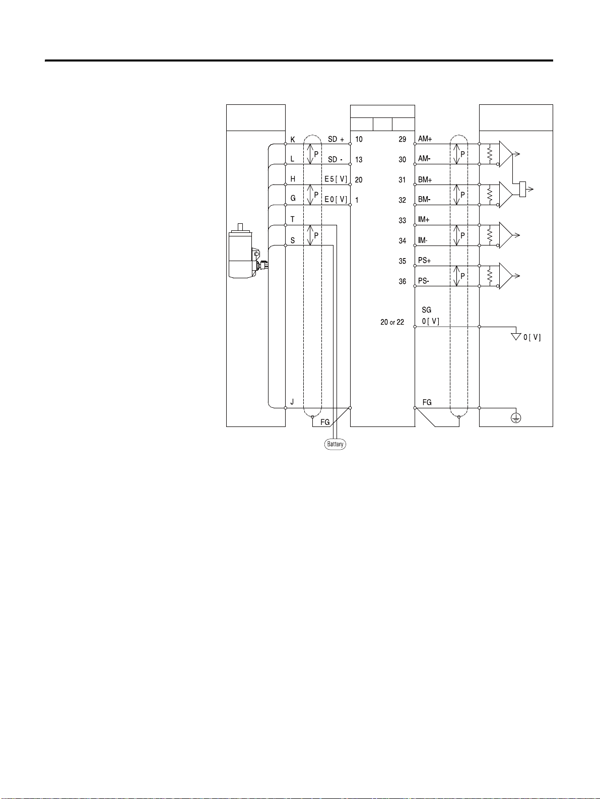
Serial encoder connection of RSMS/D/F/H/K/L motors.
Host Encoder
Servo Drive
Motor I/O
Serial I/F Circuit
Up/Down
Counter
Serial I/F Circuit
* Connect when absolute encoder is used
Wiring 3-25
25 CSD5 Servo Drive
Page 52
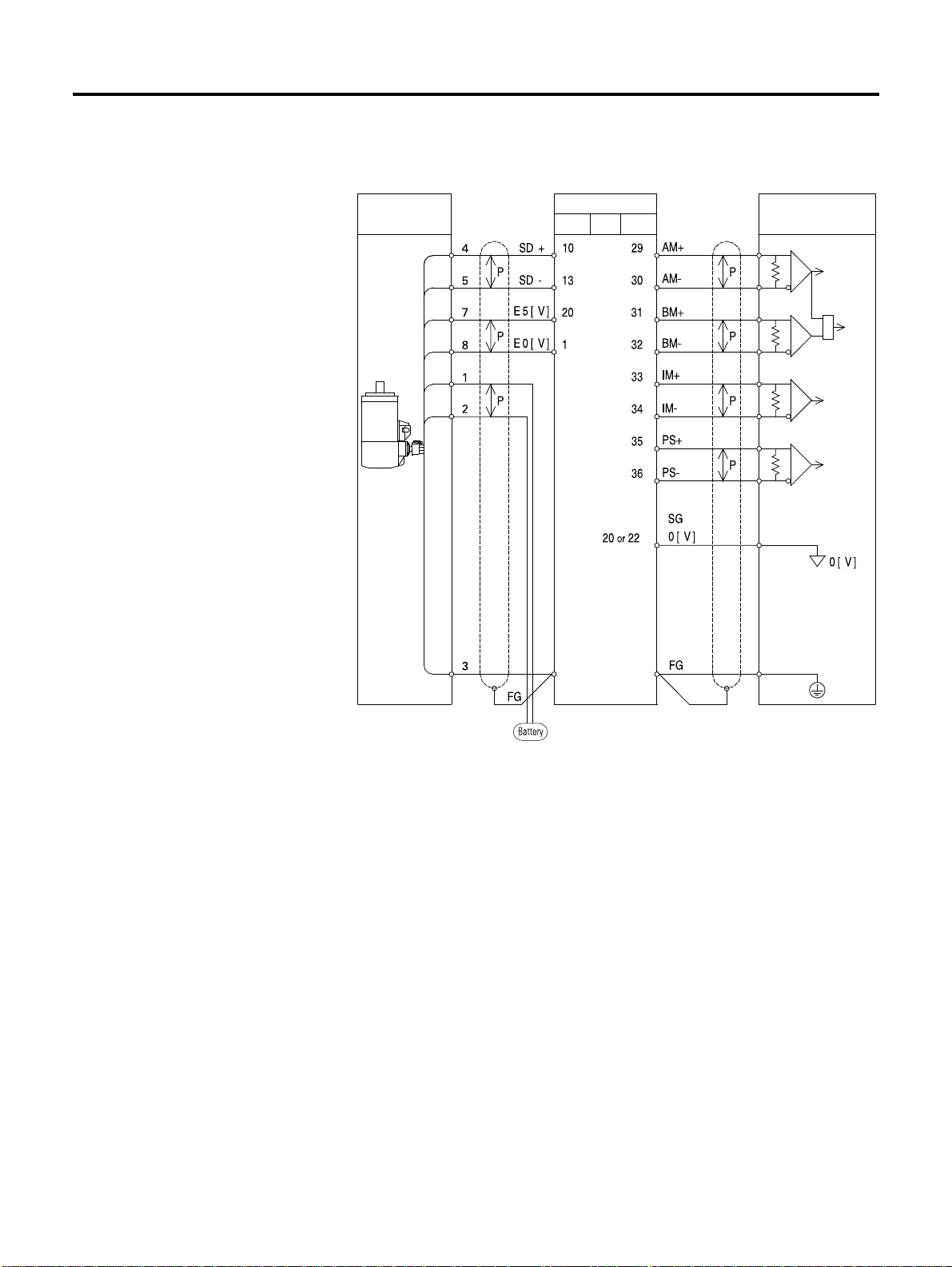
3-26 Wiring
Host Encoder
Serial I/F Circuit
Up/Down
Counter
Serial I/F Circuit
* Connect when absolute encoder is used
Servo Drive
Motor I/O
Serial encoder connection of CSMT/R, RSMKQ/Z motors (Absolute,
Incremental).
CSD5 Servo Drive
Page 53

Wiring 3-27
General Articles Wiring
This part describes wiring to implement optimum performance of the
servo drive in wiring and noise.
Precautions
Electric Circuit
• Use a thick wire as earth wire if possible.
• Class 3 grounding is recommended. (Recommendation: grounding
resistance lower than 100 [Ω ])
• Only 1 point must be grounded.
• Select ground phase and ground point considering the power conditions
of installation area. If the power is supplied by the ground phase, wire it
so that L2 of AC main power input terminal (L1, L2, and L3) becomes
the ground phase.
• Use noise filter for the main power and control power.
• Electric circuit wiring and signal circuit wiring should be apart as much
as possible. (30 [cm] or more)
• Do not use same power with the electric ARC welding machine or
discharge processor equipment.
• The earth wire of the servo motor must be connected to the grounding
terminal of the drive. In addition, ground the grounding terminal of the
drive.
• If the wiring is inside the metal pipe, ground the pipe with class 1
grounding.
Signal Circuit
• The host controller should be installed as closely as possible to the drive,
and the noise filter must be used.
• I/O (I/O signal connector) and Motor Feedback (encoder cable) should
be twist pair wire and batch shield wire.
• Note that the signal circuit wire is very thin, thus pay attention when
handling it.
• If the noise is generated at command input cable, ground 0 [V] line (SG)
of the input line before the usage.
27 CSD5 Servo Drive
Page 54

3-28 Wiring
NOTE
Refer to the servo motor manual more information on the
following cable Specifications and order code.
• Motor 3 phase power cable
• Encoder cable
• Motor brake cable
• I/O cable
• Communication cable
Others
• Use the breaker or fuse for wiring to protect the servo drive.
• Make sure there is no continuous bending and stress to the wire.
• Use noise filter in radio noise.
• If used around residential area or the radio disturbance is concerned,
install a noise filter on the input side of power line.
• As the drive is for industrial use, there are no measures for radio
disturbance.
• Attach a surge absorption circuit to the relay, solenoid, and coil of the
magnetic contactor.
Capacity of the Drive and Fuse
The table below shows the capacity of servo drive and fuse.
Table 3.13 Fuse Specifications
Drive Capacity Power Capacity per
1 Drive [kVA]
CSD5_A5BX1 50 W 0.25 4
CSD5_01BX1 100 W 0.40 4
CSD5_02BX1 200 W 0.75 4
CSD5_04BX1 400 W 1.2 8
CSD5_08BX1 800 W 2.3 8
CSD5_10BX1 1 kW 2.3 8
CSD5_15BX1 1.5 kW 3.2 10
The fuse capacity is the value when 100 [%] load is applied. When
selecting the MCCB (breaker for wiring) or fuse capacity, select the fuse
capacity considering the load ratio.
MCCB or Fuse Power
Capacity [Amps]
CSD5 Servo Drive
Page 55

Wiring 3-29
CAUTION
CAUTION
Cut-off features: 200 [%]- 2 seconds or more. 700 [%] - 0.01 second or
more.
The high -speed cut-off fuse cannot be used. As the power
of the drive is condenser input type, the fuse may be blown
even during a normal situation if the high-speed cut-off
fuse is used.
Noise Protection
The high-speed switching device and microprocessor are used at the
main circuit of the servo drive. Thus, switching noise is affected by the
connection and grounding methods. Use the proper wiring and
grounding method to prevent any affects from the noise.
Use a wire of 3.5 [mm2] or thicker for the earth wire.
Separate the signal and power wiring.
29 CSD5 Servo Drive
Page 56

3-30 Wiring
L3
L2
L1
L2C
L1C
LINE FILTER
CN 1
PP
M
CN 2
W
PG
V
U
LINE
FILTER
1
2
AVR
P
Servo Drive
3 Phase AC 200 ~ 240 [V] <50/60
Ralay Sequence Circuit
Signal Generating
Servo
Motor
Heat Sink
Ground Plate
One Point Grounding
<Class 3 Grounding or Higher>
Earth Grounding
Motor Feedback
I/O
Extra caution is required when wiring the noise filter. The following
figure describes precautions when wiring the noise filter. If the wiring is
wrong, the performance of the noise filter falls.
CSD5 Servo Drive
Page 57

Wiring 3-31
Primary and
Secondary
Interference
FILTER
Primar Secondar
FILTER
Primary and
Secondary
Interference
Primary Secondary
FILTER
FILTER
Separation of
Primar Secondar
Primar Secondar
Primar Secondar
Separation of
Primary
Secondary
FILTER FILTER
Primary
Secondary
Primar Secondar
Primary
Secondary
Primar Secondar
Separate the input and output wiring of the noise filter and do not tie up
them together.
Earth wire of the noise filter should be wired in distance to the output
wire and do not put other signal lines and earth wire in a same duct and
tie up them together.
31 CSD5 Servo Drive
Page 58

3-32 Wiring
FILTER FILTER
Primary Secondary
Primar Secondar
Primar Secondar
Primary
Secondary
FILTER
Primar Secondar
Earth wire of noise filter should be solely attached in the earth plate. Do
not connect the earth wire of the noise filter to other earth wire
together.
If there is noise filter inside the case (panel), connect all of the earth
wires and earth wires of other equipment inside of the case to the
grounding plate. And then, ground them.
CSD5 Servo Drive
Page 59

Wiring 3-33
Alarm Display Lamp
Referenc
Referenc
Reference
I/O
I/O
I/O
Wiring when Using Several Drives
This is an example of wiring when connecting several drives.
Connect the alarm output (SALM) signal of each servo drive in a series
and run Relay 1 to detect the alarm. Normally, SALM+ and SALM- are
interconnected, and with 24 [V] supplied to Relay1, the servo drive runs
normally.
If the servo alarm is generated, 24 [V] supplied to Relay1 is cut off.
1 MCCB
FILTER
NOISE
1MC
SW 1 OFF
Relay 1
L1
L2
L 3
L1C
L2C
L1
L2
L 3
L1C
L2C
1MC
SW2 ON
FAULT
FAULT
+24 [ V] IN
E- STOP
FAULT
FAULT
+24 [ V] IN
E- STOP
Relay 1
CN 1
45
+
46
-
1/2
10
CN 1
45
+
46
-
1/2
10
1MC
SUP
+24 [ V]
Relay 1
+24 [ V]
0[ V]
+24 [ V]
0[ V]
L1
L2
L 3
33 CSD5 Servo Drive
L1C
L2C
FAULT
FAULT
+24 [ V] IN
E- STOP
+
-
CN 1
45
46
1/2
10
0[ V]
+24 [ V]
0[ V]
Page 60

3-34 Wiring
NOTE
RST
AC 220 [V] Power
MCCB
Breaks the circuit if large
inruch current flows on
power line.
Noise Filter
Remove the noise from
the power line.
Renerative Resistor
Magnetic Contactor
I/O
Host
Magnetic
Contactor for the
Motor Break
Contorl
Motor Break
Control Power
Break Cable
Motor Cable
Motor Feedback
Encoder Cable
Motor Break Control
Servo Motor
RS-232/
RS485
Whether to use the emergency stop input can be set by the
parameter [Ft-0.05]; the initial value is set as not to use. Do
not wiring when it does not using the emergency stop.
Connection to Peripheral Equipment
CSD5 Servo Drive
Page 61

Chapter 4
Operator, Basic Setting and Startup
This chapter introduces the operator mounted on the servo drive. In addition,
it describes the basic setting of servo drive, and also an example for simple
startup.
Before You Begin
About Servo-ON Signal
This part describes Servo-ON signal for the control of the servo drive.
What is Servo-ON?
Audio or TV can select and play music and display channel that the users want
from the moment the power switch is on.
However, the servo drive cannot run servo motor by simple applying the
power. To complete load the system and use the servo drive, Servo-ON signal
from the host controller is required.
Servo-ON signal should be applied and maintained from the host controller
for the servo drive to run the motor. In servo -OFF status, it cannot run the
motor.
1 CSD5 Servo Drive
Page 62

4-2 Operator, Basic Setting and Startup
Powe
Powe
/SV-ON
Powe
/SV-ON
Motor
Roation
Input of command
like position, speed
Apply power to
the drive
Host
Receive
servo-On signal
Receive command such
as position, speed
Motor
rotate
Start automobile
Driver
Set transmission
at position D.
Run
accelerator
Automobil
e runs
Table 4.1 Servo-OFF and Servo-ON
Servo-OFF and Servo-ON
Servo-OFF Status Servo-ON Status Input of commands such as position, speed
regarding servo-ON status and motor run
• If the servo-ON signal is not
applied after the power
application, it is same as the
servo driver and motor being
separated completely.
• If the servo-ON signal is applied from the
host controller, the drive starts to apply
voltage to the motor . At this time, if there
is no motor run command, the drive
maintains the motor stopped.
• If the motor run command is input while the
servo-ON signal of the host controller is
maintained, the drive can run the motor according
to the command.
• This is a ready status to run the
motor.
Servo-ON Signal of the Host Controller and Running the Automobile
The following describes the servo drive in relation to the transmission of the
automobile.
CSD5 Servo Drive
As the transmission of the automobile should be positioned at 'D' to start the
automobile, the drive can be run only when the servo-ON of the host
controller is maintained.
Commands to run the motor such as the position, speed of host controller are
invalid in Servo-OFF status.
Page 63

Operator, Basic Setting and Startup 4-3
TIP
TIP
Servo-ON/OFF Signal Indication
In this manual, the Servo-ON signal is indicated as shown below.
Servo-ON, </SV-ON> Servo-OFF
Servo-ON Signal Input
Servo-ON signal from host controller is received through the sequence input
signal of I/O. Refer to the 5-1 page "Sequence I/O (Input/Output) Signal" for
the sequence I/O signals.
Servo Drive's Own Servo-ON
If the servo drive runs the motor without a command from the host controller
as in the operation mode (run-00), (run-01), the drive makes itself Servo-ON
for the operation.
• Refer to the 7-41 page "Operation Mode Function" for
the operation mode (run-00) to (run-02). In addition,
the operation mode (run-00) is described in the 4-21
page "Startup" Startup.
• (run-00), (run-01), (run-07), (run-08), (run-10), (run-12)
are not operated in Servo-ON status.
Alarm Occurrence and Servo-ON Status
If servo alarm is occurred by the self-diagnosis function of the drive while the
Servo-ON signal is applied to the drive, the drive make itself Servo-OFF to
stop the motor and displays the contents of servo alarm. Users should inspect
the contents of servo alarm, take necessary action, and reset the alarm (Refer
to the7-49 page "Alarm Reset (run-08)". At this time, if an appropriate action
against the servo alarm is taken and the servo-ON signal of host controller is
maintained, the drive returns to servo-ON status at the moment that alarm is
reset.
Refer to the 8-3 page "Servo W arning" for the information of the servo alarm.
• All parameter setting after Chapter 4 should be done
for the Servo-ON status and Servo-OFF status.
• In this manual, ‘the servo drive status’ means whether
the servo drive is in servo-ON status or servo-OFF
status.
3 CSD5 Servo Drive
Page 64

4-4 Operator, Basic Setting and Startup
Operator
Name and Function of Each Part
The servo drive has a built-in operator for various status displays, parameter
setting, operation command, and monitoring.
• Displays various contents with six 7-segment LED display.
• Provides all key manipulation function without a separate external
operator.
The following figure shows the front side of the operator on the servo drive.
1
2
4
3
Table 4.2 Name and Function of Each Part
No. Name Function
1 7-Segment LED Display Displays the status with 6-digit 7-segment LED display, sets parameter, commands operation
2 MODE/SET Key Enters display mode shift and parameter setting value.
3 ENTER Key Enters into each window after changes the display mode. Completes setting and exits from it.
4 Top, Bottom, Left/Right Key Moves the digit of 7-segment LED display and functions as the UP/DOWN of the number.
and displays monitoring.
Icons for the Key Buttons
Icon is used in description throughout the manual. Thus, be fully aware of the
shape, name and function of icons.
CSD5 Servo Drive
Page 65

Table 4.3 Icons for the Key Buttons
Operator, Basic Setting and Startup 4-5
Key Button
(1)
Name Function
Up
Down
Left
Right
Direction
Key
MODE/ SET
Key
ENTER Key
• Increases and decreases the value
• Press and hold this icon to continuously
increase/decrease the value
• Shifts the digits
• Used to indicate up, down, left, right keys
altogether
• Changes the mode
• Saves the setting value
• Start running
• To enter/exit each setting window after
changing the mode
• Select setting value
(1)
Black key button represents that it is pressed.
Structure of the Entire Mode
As shown in the figure below, the servo drive is divided into 5 types of control
modes:
The mode displayed after the power ON is the status display mode. Mode is
changed whenever the MODE/SET key is pressed. Be fully aware of the
following 5 mode types and read the following.
5 CSD5 Servo Drive
Page 66

4-6 Operator, Basic Setting and Startup
Power Connection
Status Display
Operation Mode
Parameter Setting Mode
Monitor Mode
Index Mode
The displayed values in the above figure are the initial value of each mode.
If the value is changed in a mode and then returned, the changed value is
shown instead of the initial value.
CSD5 Servo Drive
Page 67

Operator, Basic Setting and Startup 4-7
Row Display
Control Status
Point Row Display Row Disp la y
S tatus Display Mode
This section describes contents of the status display mode.
The figure below is an example of display for the description of the status
mode. Refer to the table below for the meaning of each display.
Control Mode (Ft-0.00)
Displays control mode in use. In Servo-ON status (in operation), the display of
the control mode flickers.
Table 4.4 Status Display Modes - Control Mode
Display Description
Basic Control
Mode
Combinational
Control Mode
Position mode
Speed mode
Torque mode
Multi-step speed mode
Index mode
Speed + position mode
Torque + speed mode
Torque + position mode
Multi-step speed + position mode
Multi-step speed + speed mode
Multi-step speed + torque mode
7 CSD5 Servo Drive
Page 68

4-8 Operator, Basic Setting and Startup
In combinational control mode, it performs two types of selected mode
simultaneously for the operation. And at this time, the display of the current
mode is flickered. If the mode is changed, the display of new mode flickers,
and the previous mode does not.
Status
Displays corresponding character upon servo warning.
Refer to the 8-3 page "Servo Warning" for details of the servo warning.
Table 4.5 Status Display Mode - Status
Display Description
It means the preparation for the operation in
Servo-OFF status.
Displays that it is running.
Displayed when forward operation prohibiting signal
is input.
Displayed when reverse operation prohibiting signal is
input.
Point Display
It is on if the power is applied.
Row Display
Refer to the reference pages on the right for more information on the row
display.
Table 4.6 Status Display Mode -Row Display
Description Reference
Row Display 1 When using as a position mode, if the difference between load position and position command is
smaller than [Ft-5.00] value, the servo drive can display (</P-COM> position completion detection)
signal. It is on when </P-COM> signal is displayed.
When using as a speed mode, if the difference between motor speed and speed command is smaller
than [Ft-5.03] value, the servo drive can display (</V-COM> speed coincidence detection) signal. It
is on when </V-COM> signal is displayed.
Row Display 2 When the rotation speed of the motor is higher than the setting value of rotation detection level
[Ft-5.04], the servo drive can display (</TG-ON> rotation detection) signal. It is on when </ TG-ON
> signal is displayed.
Row Display 3 It is on when Z-pulse output of the encoder is detected. In case of linear motor , it is on when first hall
U signal is detected
page 5-28
page 5-38
page 5-39
CSD5 Servo Drive
Page 69

Operator, Basic Setting and Startup 4-9
To
From
Overview of the Parameter Setting Mode
This section includes brief explanation of the parameters in parameter setting
mode.
The Parameter sets and saves various functions to make drive suitable for
equipment.
There is a parameter that can be always set regardless of the status of the drive,
and those that must be in certain status of the drive when setting them. Be
careful to set parameter in reference to the contents in the Appendix B "Table
for Parameter Setting".
The contents related to parameter setting are described in details in Chapter
#5, 6, 7, 8 and the Appendix along with the functional description of the servo
drive.
The table below is to aid the understanding of parameter group.
Parameter range:
Table 4.7 Parameter Group
Parameter Group Parameter Group Description
Group 0 Ft-0.00 ~ Ft-0.32 33 User parameter related to basic setting and
Group 1 Ft-1.00 ~ Ft-1.42 43 User parameter related to gain and gain
Group 2
Group 3 Ft-3.00 ~ Ft-3.08 9 User parameter related to position control
Group 4 Ft-4.00 ~ Ft-4.06 7 User parameter related to torque control
Group 5 Ft-5.00 ~ Ft-5.16 17 User parameter related to supplementary
Ft-2.00 ~ Ft-2.13 14
I/O signal
tuning
User parameter related to speed control
mode
mode
mode
function
9 CSD5 Servo Drive
Page 70

4-10 Operator, Basic Setting and Startup
To
From
Overview of the Monitor Mode
This section includes brief explanation of the parameters in monitor mode.
Displays several numerical data generated as the motor is controlled by the
drive. The contents of the monitor mode can be checked regardless of the
status of the drive. Be fully aware of the numbers and units displayed in
monitor mode shown in the table below and refer to it when using the servo
drive.
The table below shows the brief contents of each item in the monitor mode.
Monitor Mode Range:
Table 4.8 Monitor Mode
Item Monitor Contents [Unit]
dIS-00 Speed feedback [rpm or mm/sec]
dIS-01 Speed command [rpm or mm/sec]
dIS-02 Speed error [rpm or mm/sec]
dIS-03 Torque command [%]
dIS-04 Position feedback [pulse]
dIS-05 Position command [pulse]
dIS-06 Position error [pulse]
dIS-07 Position command pulse frequency [kpps]
dIS-08 Electrical angle [ °]
dIS-09 Mechanical angle [ °]
dIS-10 Accumulated load rate of regenerative resistor [%]
dIS-11 DC Link voltage [V]
dIS-12 The number of rotation data of absolute encoder
dIS-13 Speed command offset [mV]
dIS-14 Torque command offset [mV]
dIS-15 I/O status
dIS-16 Alarm history
dIS-17 Firmware version
dIS-18 Motor & Encoder Type
dIS-19 Analog speed command vol [0.01V]
dIS-20 Analog torque command voltage [0.01V]
CSD5 Servo Drive
Page 71

Operator, Basic Setting and Startup 4-11
To
From
Table 4.8 Monitor Mode
Item Monitor Contents [Unit]
dIS-21 Drive rated output
dIS-22 Absolute encoder 1-time rotation data
dIS-23 Encoder feedback counter
The items like Posiotn feedback, Potion Command, and Encoder Feedback
Counter of the monitor mode Posiotn feedback, whose value is more than 6
digits, is not displayed at once by the 6-digit 7-segment LED display.
Therefore, it is displayed seperatly by left and right key. Refer to the 7-52 page
"Monitor Mode Function"for details on how to check such items.
Overview of the Operation Mode
This section includes brief explanation of the parameters in operation mode.
The motor can be run in operation mode. Each item provides a special
function, which can be used. Just as in the parameter setting mode, there is a
status where the operation is possible/impossible according to the status of
the servo drive, during the use of the operation mode. Refer to the 7-41 page
"Operation Mode Function"for details of operation mode.
The table below shows the brief functions of each item in the operation mode.
Operation Mode Range:
Table 4.9 Operation Mode
Item Operation
run-00 Jog operation
run-01 Off-line auto tuning
run-03 Auto adjustment of the speed command offset
run-04 Auto adjustment of the torque command offset
run-08 Alarm reset
run-10 Absolute encoder reset
run-11 2-group gain storing
run-12 Parameter initialization
Refer to the 7-41 page "Operation Mode Function" for details of operation
mode and key button manipulation.
11 CSD5 Servo Drive
Page 72

4-12 Operator, Basic Setting and Startup
Basic Setting
Table 4.10 Basic Setting
This section includes the introduction of the control mode and the basic
setting.
Overview of the Basic Setting
Basic setting must be done before using the servo drive.
• Other parameters can be set after the basic setting.
• The basic setting is possible only after connecting the control power of
the servo drive.
• After all setting three types of basic setting, reapply the power.
• The setting values of the basic setting are saved even if the power is cut
off or parameter is initialized by [run-12] function of the operation
mode.
• To change basic setting value, change it directly from corresponding
parameter and reapply the power.
As shown below, the basic setting uses two parameters to set 2 types.
Basic Setting Parameter Setting
1
2
Control mode (optional) setting
Motor setting
• Motor type setting
• Motor capacity (rated output) setting
• Encoder type setting
The key button manipulation flow chart is provided in the description of the
basic setting to aid the understanding of the key buttons. While performing the
basic setting, get accustomed to key button manipulation. Key button
manipulation flowchart is not described after Chapter 5.
The following figure is an example of the nameplate attached to the motor.
Before performing basic setting, be sure to check the following three contents
of the model name.
Before mounting a motor to the equipment, check the model name of the
motor in advance. Depending on the motor type, the motor may be mounted
in such direction that the nameplate is not visible.
CSD5 Servo Drive
Page 73

Operator, Basic Setting and Startup 4-13
R S M Z
-
0 1 B A 1 A N K 3
< >
Select a Motor Check the model name on the motor
nameplate
Example of
Motor Type Rated Output Encoder Type
Control Mode Setting
Control Mode Type
As in the table below, there are 5 kinds of basic control modes and 6 kinds of
associated control modes. The table below shows the control mode types.
Refer to the Chapter 5 for function for each control mode.
Table 4.11 Contorl Mode Type
Display Description
Basic Contorl
Mode
Associated
Control Mode
Position mode
Speed mode
Torque mode
Multi-step mode
Index mode
Speed + position mode
Torque + speed mode
Torque+ position mode
Multi-step speed + position mode
13 CSD5 Servo Drive
Multi-step speed + speed mode
Multi-step speed + torque mode
Page 74

4-14 Operator, Basic Setting and Startup
Flowchart of the Contorl Mode
Status Display Mode
Select Parameter Setting Mode by
MODE/SET key
Press ENTER key and
Enter into the Setting Window
Using the Direction key, Create a Contorl Mode to Set
Displays Contol Mode by UP-DOWN key
An Alphabet representing each mode is displayed.
Multi-step Speed
Torque
Speed Control Positon
Control Mode Selection Completion
Press MODE/SET key to save it.
The Setting window blinks and it is saved.
To complete the setting, turn power off and on again.
Control Mode Setting Method
Describes control mode setting method focusing on the key button
manipulation.
Apply the power and set it as shown in the flowchart below.
Combinational Control Mode Setting
Combinational control mode should be set as below.
Table 4.12 Combinational Control Mode
Associated Control Mode Setting Window Display
Speed + position control
Torque + speed control
Torque + position control
CSD5 Servo Drive
Page 75

Operator, Basic Setting and Startup 4-15
CAUTION
Table 4.12 Combinational Control Mode
Associated Control Mode Setting Window Display
Multi-step speed + position
control
Multi-step speed + speed
control
Multi-step speed +Torque
control
The following are the precautions in setting associated
control mode.
• Combinational control mode cannot be used by
combining more than 3 types. Make sure to combine
two types only.
• If the setting is correctly entered, the setting window
blinks once when MODE/SET key is used to save the
data. However, if wrong setting is entered, it does not
blink nor is saved.
15 CSD5 Servo Drive
Page 76

4-16 Operator, Basic Setting and Startup
C S M T - 0 1 B A 1 A N T 3
Motor Type Rated Output Encoder Type
Motor Setting
Select a motor to connect to the servo drive and set three items of the motor.
If a motor to connect to the drive is selected, verify the nameplate on the
motor. Motor setting is divided into three items as below.
Motor setting should be done from the parameters [Ft-0.01]. As shown in the
following figure, the setting window of [Ft-0.01] has a predefined place for
each item, and the same alphabet as the ones on the model name of the motor.
(Use both capital letters and lowercase letters).
Motor Type
Motor types of the servo motor are indicated in 4 digits, and the code starts
with CSM for all motors. Thus, the first 3-digit, CSM, is omitted in the display
of the motor. If first disit is displayed 'r', it sets RSMx motor serieses.
Table 4.13 Motor Type
Display Model
CSMT
CSMR
CSMQ
CSMZ
RSMS(2004-RS**)
RSMD(2004-RD**)
RSMH(2004-RH**)
RSMF(2004-RF**)
CSD5 Servo Drive
Page 77

Operator, Basic Setting and Startup 4-17
Table 4.13 Motor Type
Display Model
RSMK(2004-RK**)
RSML(2004-RL**)
RSMQ(2004-RQ**)
RSMZ(2004-RZ**)
Rated output (Capacity)
Rated output (capacity) and display of the motor are shown below.
Table 4.14 Motor Rated Output
Display Capacity
30 [W]
50 [W]
...
100 [W]
200 [W]
...
1 [kW]
1.5 [kW]
...
...
Encoder Type
In encoder type set, serial absolute encoder transmits encoder data to the drive
and automatically performs setting as it is connected to the drive. The encoder
type display is shown below.
17 CSD5 Servo Drive
Page 78

4-18 Operator, Basic Setting and Startup
Table 4.15 Encoder Type Group 1
Motor Series Display Number of
CSMT/R 131072
CSMT, CSMR, CSMQ, CSMZ
Pulse/1 Rotation
(resolution)
2048 9 wire Inc.
2500 11 wire Inc.(CSMQ/Z Only)
2048 Compact Absolute (CSMQ/Z Only)
Table 4.16 Encoder Type Group 2
Motor Series Display Number of
RSMS/D/H/F/K/L
RSMZ/Q
Pulse/1 Rotation
131072(resolution)Serial Absolute
Encoder Type
Serial Absolute
Serial Inc.
Encoder Type
Serial Inc.
2500 9 wire Inc.
2048 Compact Absolute (RSMZ Only)
CSD5 Servo Drive
Page 79

Operator, Basic Setting and Startup 4-19
Precautions
Setting sequence is in order of motor model, rated output (capacity), and
encoder type. The encoder type is classified into group 1 and group 2,
according to motor model, and an encoder that corresponds to each motor
type is displayed. In addition, only the rated output of the motor that
corresponds to the type selected is displayed only. A setting example of an
encoder in the encoder type 1 is shown in the following motor setting
flowchart.
• In the following flowchart, the encoder type is in order of S, B, A, D, C,
Q, and R.
• In case of using a model in encoder type 2, the encoder type is displayed
in order of K, L, H, A, M, Q, and R .
The table below is a setting example for each motor type.
Motor model number setting
CSMT-04BQ1ANT3
RSMD-10BA1ASK3
19 CSD5 Servo Drive
Page 80

4-20 Operator, Basic Setting and Startup
Flowchart of Motor Setting Selection
Status Display Mode
Select Parameter Setting Mode
by MODE/SET key
Press ENTER key and Enter
into the Setting Window
Find Setting value from the Setting Itmes suitable for Each Digit
Find Setting Value of the Setting item by Move to the Setting Item by
Motor Type Rated Encode
Motor Setting Completion
Press MODE/SET key to save it.
The Setting Window blinks and it is saved.
To complete the setting,turn Power off and on again completion
Motor Setting Flowchart
Basic setting is all finished for the use of the drive. Reapply the power.
• To connect other motor type after completing the basic setting of motor
connected to the servo drive initially, or to change the parameter setting
at the basic setting, be sure to enter into corresponding parameter and
change it.
• Basic setting value is preserved even if the power is cut off or the
parameter is initialized (Refer to the 7-51 page "Parameter Initialization
(run-12)") .
CSD5 Servo Drive
Page 81
Operator, Basic Setting and Startup 4-21
CAUTION
• A flowchart for the key button manipulation is included in the
description of the basic setting of the servo drive to help the
understanding of the key button manipulation. But, it is not provided in
Chapter 6, 7 and 8. Read the following section on startup, and get
accustomed to the manipulation of the key buttons.
Startup
Before Startup
1. Please be aware of wiring in Chapter 3 and connect main power and
control power normally. In addition, by configuring emergency stop
input circuit, clear the emergency stop status.
2. Connect the motor and encoder properly.
3. Pereform basic setting in reference to the 4-12 page "Basic Setting".
4. Do not connect the load to the motor for safety purposes. If the motor
is mounted on the equipment, remove coupling of the motor shaft so
that load may not move.
Caution when Startup
• To prevent the injury, check the operation range of the
motor shaft or load upon operation, and keep it away
from the drive.
21 CSD5 Servo Drive
• Run the drive after preparing the E-stop circuit. Then,
you can cope quickly with an emergency situation.
• Refer to the 3-18 page "Emergency Stop Signal"for
E-stop information.
Startup
Start up 1: Start up the Drive by Using Jog Operation Function.
The jog operation is possible in Servo-OFF status. Remove the wiring between
the drive and the host controller, or apply Servo-OFF signal from the host
controller.
Page 82

4-22 Operator, Basic Setting and Startup
Flowchart of the Startup using Jog Operation [run-00]
Status Display Mode
Select run mode
by MODE/SET key
Create [run-00] by
Direction
End
Turn Power On
Press ENTER and check
JOG operation
Press MODE/SET key
prepare JOG-ON operation
The Motor runs conter clockwise
while pressing the UP key
The Motor runs clockwise while
pressing DOWN key
Press MODE/SET key and
clear JOG-OFF operation
Press ENTER key and
clear JOG-OFF operation
The speed of the motor can be set from the drive for the jog operation. The
initial value of the jog operation speed is 50 [rpm]. At startup 1, runs the drive
at the factory setting speed, 50 [rpm].
Start up the drive according to the following flowchart.
CSD5 Servo Drive
Page 83

Operator, Basic Setting and Startup 4-23
TIP
Flowchart of the Jog Operation Speed Change
Status Display Mode
Select parameter setting
mode by MODE/SET key
Create [Ft-2.01] by
Direction key
End
Trun Power On
Press ENTER and enter
into the Setting Window
Create 1000 [rpm]
by Direction key
Press MODE/SET key
to save. Blink!
Press ENTER to Exit
Start up 2: Start Up the Drive by Changing the Speed
Start up the drive by changing the speed from the initial value, 50 [rpm] to
1000 [rpm].
The change of Jog operation speed should be done at [Ft-2.01]. The speed set
here is not related to other operation, and applied only upon the Jog operation.
Setting range is 0 to 6000 [rpm]. Initial value is 50 [rpm].
Change the Jog operation speed by according to the following flowchart.
If setting is wrong, the setting window does not blink when saving it by
pressing the MODE/SET key. If setting is completed normally, retry the Jog
operation [run-00]. You can see that the speed is changed from 50 [rpm] to
1000 [rpm].
• At first, the drive is not tuned suitable for the load or
motor.
• Upon startup, first perform off-line auto
tuning(run-01) described in the 7-44 page "Off-line
Auto Tuning Operation (run-01)" then startup the
drive to run the motor more smoothly in a stable
condition.
23 CSD5 Servo Drive
Page 84

4-24 Operator, Basic Setting and Startup
CSD5 Servo Drive
Page 85

Chapter 5
Function for Control Mode
This chapter describes the sequence input/output function of I/O signal
connector CNI and the function for each control mode.
Sequence I/O (Input/
Output) Signal
What is Sequence I/O Signal?
To provide the optimum performance that is suitable for user’s equipment, 50
pin connector of I/O is used to allow the drive can input/output signals that
have various functions.
Input provides 25 functions and you can freely allocate input signal of each
function with 10 pins.
Output provides 16 functions and you can freely allocate output signal of each
function with three pairs of pins such as (41, 42), (43, 44), (47, 48) and pin
(37~40) of I/O.
Sequence I/O signal means the I/O signal of various functions that are
required for servo drive control by the host controller.
Sequence I/O signal is not to process input or output signal with the
designated pin of I/O, but to select the function that the user requires in terms
of circuit design of host controller and to directly allocate the selected
functions to the designated pin.
Therefore, the host controller can do the sequential control that fits to the
equipment to operate servo drive.
The following figure is sequence I/O part among 50 pins of I/O.
• Sequence Input is indicated as (INPUT#1) to(INPUT#10). (Digital
Input Channel)
• Sequence Output (OUTPUT#1) to (OUTPUT#6). (Digital Output
Channel)
1 CSD5 Servo Drive
Page 86

5-2 Function for Control Mode
I/O 50-Pin Connector <I/O>
Input
Sequence
Input Circuit
Output
Sequence Output
24V [or GND]
1
GND [or 24V]
INPUT1 (/SV-ON)
INPUT2 (P-OT)
INPUT3 (N-OT)
INPUT4 (/P-CON)
INPUT5 (/A-RST)
INPUT6 (/N-TL)
INPUT7 (/P-TL)
INPUT8
INPUT9
INPUT10
2
3
4
5
6
7
8
9
26
27
28
Function of Input Signal
37
FAULT 1/ OUTPUT 4
38
FAULT 1/ OUTPUT 5
39
FAULT 1/ OUTPUT 6
40
FCOM/OUTCOM
41
OUTPUT1+ (P_COM+)
P
42
OUTPUT1- (P_COM-)
43
OUTPUT2+ (TG_ON+)
P
44
OUTPUT2- (TG_ON-)
47
OUTPUT3+ (BK+)
P
48
OUTPUT3- (BK-)
T able 5.1 I/O Sequence Input Signal
Type Description Mode Reference
</SV-ON> Servo-ON When input is ON, voltage is applied to the servo motor and
</A-RST> Alarm reset It releases the servo alarm. All
</G-SEL> Gain gorup
conversion
</P-TL> Limit forward torque When a signal is on, it limits forward tor que by the setting va lue
CSD5 Servo Drive
The following is the brief explanation on 25 functions of sequence input
signal. Details for each signal are explained in the reference pages listed on the
right side of the table.
when input is off, the voltage is cut off.
Use 2 group gain for the section where input is on, and current
gain for the section where input is OFF. It converts gain of 2
groups.
[Ft-4.03].
All page 4-1
page 7-49
All
All
page 6-36
page 5-46
Page 87

Function for Control Mode 5-3
Table 5.1 I/O Sequence Input Signal
Type Description Mode Reference
</N-TL>
Reverse Torque Limit
<P-OT> Prohibit forward
operation
<N-OT> Prohibit reverse
operation
</P-CON> P Control
Conversion
</C-SEL> Control mode
conversion
</C-DIR>
</C-SP1>
</C-SP2>
</C-SP3>
</C-SP4>
Ter minal speed command
</Z-CLP> Zero clamp When analog command value in the speed control is lower than
</INHIB> Inhibit pulse
command
</ABS-DT> Absolute encoder
data transmission
</PCLR>
Position Error Clear
</START> Start Control motor rotation start or stop by using terminal signal in
</GEAR>
Electronic Gear Rate Shift
</R_ABS>
Absolute encoder
multi-rotation data reset
</BANK_SEL> Gain bank
select
</
A-CL> Analog torque limit The Current Limit Function is activated by the analog torque
</H_SENS> Home sensor When activated, the sensor indicates the Return to Home
</SHOME> Start homing When activated, the system starts returning to home. I
</PAUSE> Index pause When activated, it decelerates until stop and pause the index
</STOP> Index stop When activated, index movement ends. I
When a signal is on, it limits reverse torque by the setting value
[Ft-4.04].
It prohibits a motor from rotating forward when the load part
reaches to the limit of available section.
It prohibits a motor from rotating to the reverse direction wh en
the load part reaches to the limit of available section.
It converts the Seed Controler from PI type controller to P type
controller. It is used to suppress the overshoot of the excessive
response and complete a faster response.
It is used to convert the control mode when using Mixed control
mode.
The rotation direction</C-DIR> and rotation speed </C-SP1 to /
C-SP4> of the motor are determined by the above input in
terminal speed control mode. Rotation speed of </C-SP1 to /
C-SP3> is set in [Ft-2.05 to Ft-2.11]. Rotation speed of </
C-SP4> is set by analog speed command voltage. </C-DIR> is
used to change motor rotation direction in speed control mode.
the setting value of speed zero clamp level [Ft-5.05], the input
value is ignored.
It ignores position command pulse in the section where the
signal is on.
Transmits absolute encoder data to host controller through EA
and EB when the signal is ON.
Clear position command, position feedback, and position error. F, I
speed or terminal speed control mode.
In position control mode, the 2nd electronic gear parameters
[Ft-3.05] and [Ft-3.06] are used when input is ON. The basic
electronic gear parameters [Ft-3.01] and [Ft-3.02] are used when
input is OFF. Switch between two electronic gear ratios.
Reset the multi-rotation data of the absolute motor. All
Uses the 3rd and the 4th Gain Bank when it is set to ON. Uses
the 1st and 2nd Gain Bank when it is set to OFF.
command input values when it is set to ON.
sequence that is detected.
sequence. It decides whether to stop or to continue the motion by
constantly monitoring the input status.
All
All
All
F, S, P, I
Combinational
Control Mode
Only
P
S
F
F, I
S, P
F
All
S, P
I
I
page 5-46
page 7-2
page 7-2
page 6-30
page 5-57
page 5-52
page 5-35
page 5-25
page 7-50
page 5-25
page 5-37
page 5-27
page 7-34
page 6-37
3 CSD5 Servo Drive
Page 88

5-4 Function for Control Mode
T able 5.1 I/O Sequence Input Signal
Type Description Mode Reference
</I_SEL0>
Index selection 0 Input
</I_SEL1>
Index selection 1 Input
</I_SEL2>
Index selection 2 Input
</I_SEL3>
Index selection 3 Input
</I_SEL4>
Index selection 4 Input
</I_SEL5>
Indexselection 5 Input
</H_STOP> Stop homing Stops Homing operation when it is set to ON. I
</ST ART_I> Start indexing Start Indexing operation when it is set to ON. I
</ABS-MD> Absolute
Position Data Transfer Mode
Used for the combinations to allocate indexes. I
Absolute Data transfered to host contoller by photo coupler
output which output Fault Code when it is set to ON.
F
Function of Output Signal
The following is the brief explanation on 8 functions of sequence output
signal. Details for each signal is explained in the pages listed on the right side
of the table.
Table 5.2 I/O Sequence Output Signal
Type Description Mode Reference
</S_ALM> Alarm It is on when the servo warning is detected. All page 8-5
</P-COM (+, -)> Positioning
Completion detection
</NEAR (+, -)> Positioning
approach detection
</V-COM (+, -)> Speed
coincidence detection
</TG-ON (+, -)> Rotation
detection
</T-LMT (+, -)> Torque limit
detection
</V-LMT (+, -)> Speed limit
detection
<BK (+, -)> Breaker control It is the signal f or control of the br ake that is mounted inside and
</A_VLD> Absolute position
valid
</RDY> Drive ready Me ans getting the opera tion ready while in the Servo-OFF
It is on when the position error is within the output width of
position completion signal [Ft-5.00].
It is on when the position error is within the output width of
position approach signal [Ft-5.02].
It is on when the speed difference between command speed and
the rotation speed are within the output width of speed
coincidence signal [Ft-5.03].
It is ON when the motor rotates with the speed more than the
setting value of rotation detection level [Ft-5.04].
It is on when motor torque is reached the setting value of torque
limit.
It is on when motor speed is reached the setting value of speed
limit.
outside of the servo motor.
Turns to ON when the absolute position data is valid while using
the absolute motor.
status.
F, I
F, I
F, S, P, I
All
All
All
All
All
All
page 5-28
page 5-28
page 5-38
page 5-39
page 5-46
page 5-41
page 7-6
CSD5 Servo Drive
Page 89

Function for Control Mode 5-5
TIP
Table 5.2 I/O Sequence Output Signal
Type Description Mode Reference
</WARN (+, -)> Warning Turns to ON when a Servo warning is detected. All
</HOMC(+,-)> Axis homing When activated, it shows the completion of the Homing
</IMO (+,-)> In motion Turns to ON when in motion. I
</I_DW> In dwell When activated, it indicates that the motor is on the hold
</O_ISEL0>
Index selection 0 Output
</O_ISEL1>
Index selection 1 Output
</O_ISEL2>
Index selection 2 Output
</O_ISEL3>
Index selection 3 Output
</O_ISEL4>
Index selection 4 Output
</O_ISEL5>
Index selection 5 Output
</E_SEQU> Sequence
operation completion
operation.
position in the index movement and on stand-by for the dwell
time assigned.
Used to output the index number in use in the selected indexing
operation.
Turns to ON when the index movement is complete. I
I
I
I
page 8-3
The sequence I/O signal name is indicated by < > in this
manual.
Ex) </SV-ON>, </P-COM>
Input Signal Allocation Method
Refer to the table below to allocate to I/O pin by searching the function that is
suitable for your condition.
As shown in the table below, the related function is already allocated to the
sequence input parameter and its position in the setting window and it means
that you use the related function as setting certain value among‘1 to A’ except
‘0’ to the setting position.
For example, if you want to put certain function to I/O No. 5 pin, you can
find the related parameter of that signal and the position in the setting window
according to the table below and enter ‘3’ as the setting value.
Enter ‘0’ when the function of input signal is not used. If you want to make
input signal ‘ON’ all the time regardless of the wiring, set as ‘b’.
5 CSD5 Servo Drive
Page 90

5-6 Function for Control Mode
T able 5.3 I/O Sequence Input Signal
Setting Valueb A9876543210
Input Channel
No.
I/O Pin No. 2827269876543
Always
valid
INPUT
#10
INPUT#9INPUT#8INPUT#7INPUT#6INPUT#5INPUT#4INPUT#3INPUT#2INPUT#1Always
The following table is to arrange the parameter for each function and
7-segment number position in the setting window. Set so that the related
parameter of each signal and the number position in the setting window is not
in the wrong.
Table 5.4 7-Segment Number Position of Input Signal Parameter
Parameter 7-Segment Position
321 0
</P-CON>
Initial value:
4
</C-SEL>
</C-SP3> </C-SP2> </C-SP1> </C-DIR>
<N-OT>
Initial value:
b
</P-TL>
Initial value:
7
<P-OT>
Initial value: b
</N-TL>
Initial value: 6
</SV-ON>
Initial value:
1
</A-RST>
Initial value:
5
invalid
</PCLR> </G-SEL> </INHIBIT> </Z-CLP>
</GEAR> </C-SP4> </START> </ABS-DT>
</ABS-MD> </A-CL> </BANK_SEL> </R_ABS>
</PAUSE> </STOP> </SHOME> <H_SENS>
<I_SEL3> <I_SEL2> <I_SEL1> <I_SEL0>
</START_I> </H_STOP> <I_SEL5> <I_SEL4>
CSD5 Servo Drive
Page 91

Function for Control Mode 5-7
The table below is the example to allocate sequence input signal.
Example
Enter ‘7’ in the 3rd position in setting window of the parameter
[Ft-0.01].
This value is set to use </P-CON> function. It means that the I/O
INPUT#7 pin is used as an input pin.
Applicable
Models
All
Other
Details
Drive Disable > Configure > Completed
Output Signal Allocation Method
Refer to the table below to allocate to I/O pin after searching the function that
is suitable for your condition.
Set the setting value as ‘0’ when the output of the related signal is not used.
Sequence output is displayed when situation that is meets the condition of
each ouput in drive was produced.
Table 5.5 I/O Output Signal Allocation
Setting Value
Input Channel No. OUTPUT #6 OUTPUT #5 OUTPUT #4 OUTPUT #3 OUTPUT #2 OUTPUT #1 Always Invalid
I/O Pin No. 39.40 38.40 37.40 47, 48 43, 44 41, 42
The following table is to arrange the parameter for each function and
7-segment number position in the setting window. Set so that the related
parameter of each signal and the number position in the setting window is not
in the wrong.
Table 5.6 7-Segment Number Position of Output Signal Parameter
7-segment Position
Parameter3210
</V-COM> </BK>
Initial value: 3
</WARN> </NEAR> </V-LMT> </T-LMT>
</TG-ON>
Initial value: 2
</P-COM>
Initial value: 1
Reserved Reserved </RDY> </A_VLD>
7 CSD5 Servo Drive
Page 92

5-8 Function for Control Mode
Status Display Mode
Table 5.6 7-Segment Number Position of Output Signal Parameter
</O_ISEL0> </HOMC> </I_DW> </IMO>
</O_ISEL4> </O_ISEL3> </O_ISEL2> </O_ISEL1>
Reserved Reserved </E_SEQU> </O_ISEL5>
The table below is the example to allocate sequence output signal.
Example
Set ‘3’ in the 3st position in setting window of the parameter
[Ft-0.23].
It is set to use </WARN> function and it means that we will use I/
O No. Output#47,48 pin as output pin.
Applicable
Models
All
Other
Details
Drive Disable > Configuration> Completed
Notice for Signal Allocation
When you allocate the different functions to the same pin of I/O as shown
below, the drive indicates servo warning in the status mode.
Set ‘4’ in the 2nd position in setting window of the
parameter [Ft-0.11].
It is set to use </N-TL>function and it means that I/O No.
INPUT#4 pin is used as an input pin
Set ‘4’ in the 2nd position in setting window of the
parameter [Ft-0.13].
It is set to use </INHIB> function and it means that I/O No.
INPUT#4 pin is used as an input pin.
When you allocate more than two signals to the same pin as described above,
the servo warning is indicated.
In this case, when you reapply the power after completing
the input allocation, the status display mode indicates servo
warning (Pin).
Check if you allocate more than two signals to the same pin
of I/O.
CSD5 Servo Drive
Page 93

Function for Control Mode 5-9
TIP
• Through monitor mode in the 7-52 page "Monitor
Mode Function", you can check if the sequence I/O
signal is input.
• E-STOP lamp (Emergency stop) uses the fixed input
pin of I/O contrary to sequence input according to the
allocation.
• SALM +, - lamp (Servo alarm) uses the fixed output
pin of I/O in contradiction to sequence output
according to the allocation.
• Servo drive has self-diagnostic function.
• The (servo alarm) and (servo warning) is divided
according to the importance of error diagnostic. For
the details, see Chapter 8.
9 CSD5 Servo Drive
Page 94

5-10 Function for Control Mode
Flowchart for Position Control Mode Operation
Select Sequence I/O function and allocate them.[Ft-0.10] ~ [Ft-0.31]
Set the Position Command Pulse and Signal Type according to the Host Contreller Output,
[Ft-3.00]
Startup the Motor in Position Contorl Mode as Low-speed Pulse Command Frequency is
Check the Position Pulse Command
(dis-07) in Monitor Mode.
OK ?
Set the Electronic Gear.[Ft-3.01], [Ft-3.02]
Check the Speed Command (dis-01) in
Monitor Mode.
OK ?
Set the Direction of Encoder Ouput Pulse and Division Ratio. [Ft-3.00], [Ft-3.03],
Tune the Servo Drive by Adjusting the Gain according to the Load Condtion.
No
Yes
No
Yes
Position Control Mode
Overview
The position control mode is used when the position command pulse is
received from the host controller to move the load to a target position.
To operate the servo drive in position control mode, connect the position
command pulse signal to PULS and SIGN input pins, connect other necessary
input signals and set as follows.
CSD5 Servo Drive
Page 95

Function for Control Mode 5-11
16-bit
A/D
12-bit
A/D
INPUT8
INPUT9
INPUT10
24V_PULS+
HF_SIGN -
HF_SIGN +
HF_PULS -
HF_PULS +
SIGN -
SIGN +
24V_SIGN+
PULS -
PULS +
E-STOP
INPUT
OUTPUT
OUTPUT1+
OUTPUT1-
OUTPUT3+
OUTPUT3-
OUTPUT2+
OUTPUT2-
Z-PULSE +
Z-PULSE -
FAULT +
FAULT -
CN1
FCOM/OUTCOM
AM +
AM -
BM +
BM -
IM +
IM -
PS +
PS -
24V [or GND]
GND [or 24V]
FAULT 1 / OUTPUT 4
FAULT 3 / OUTPUT 6
FAULT 2 / OUTPUT 5
1
9
8
7
6
4
3
2
5
26
27
28
10
22
21
20
19
24
16
15
14
13
25
12
11
49
23
50
36
35
34
33
32
31
30
40
39
38
37
29
48
47
44
43
42
46
45
18
17
41
P
P
P
P
P
P
P
P
P
150
150
INPUT1 (/SV-ON)
(1)
INPUT2 (P-OT)
(1)
INPUT3 (N-OT)
(1)
INPUT4 (/P-CON)
(1)
INPUT5 (/A-RST)
(1)
INPUT6 (/N-TL)
(1)
INPUT7 (/P-TL)
(1)
2
2
24 [V] Active
Low/High
Programmable
Digital Input
Analog Alarm Code
Output
Analog Alarm Code
GND
Encoder Division
Absolute Position
Serial Output
Encoder
Marker Pulse
Alarm Output
24 [V]
Programmable Digital
Output
Position
High Postion
Command
Speed
Command
Torque
Command
I/O
S tandard Wiring Example
The following figure illustrates the standard wiring example of position control
mode. You can set the sequence input/output signal, as you want if it is
necessary for the system configuration.
11 CSD5 Servo Drive
Position Command Pulse
10 pins of I/O receive 3 kinds of commands related to the position control
mode.
Host controller sends the position command with the pulse input and sign
input.
When the position control mode is used, there are line drive method, high
speed line drive and open collector method as the input types of the host
controller. The servo drive supports three types of input.
Page 96

5-12 Function for Control Mode
SIGN -
SIGN +
PULS +
P
13
14
12
11
P
PULS -
Line Drive Pulse Input
Host
I/O
Pulse Input
Signal
Line Dirve
Corresponding
SN75174
Host
P
150 [Ω]1 [kΩ ]
2.8 [V] ≤ (H Level) - (L Level) ≤
I/O
High Speed Line Drive
Pulse Input
Host Contoller
I/O
Pulse Input
Signal
HF_PULSHF_SIGN
HF_PULSHF_SIGN
HF_PULSHF_PULS
HF_PULSHF_PULS
When It is Line Drive Output
Maximum allowable frequency
• For the line drive output : 900 [kpps]
• For the high speed line drive output : 3 [Mpps]
Following circuit shows above figure.
PULS +
P
P
PULS -
SIGN +
SIGN -
15
16
23
24
CSD5 Servo Drive
Page 97
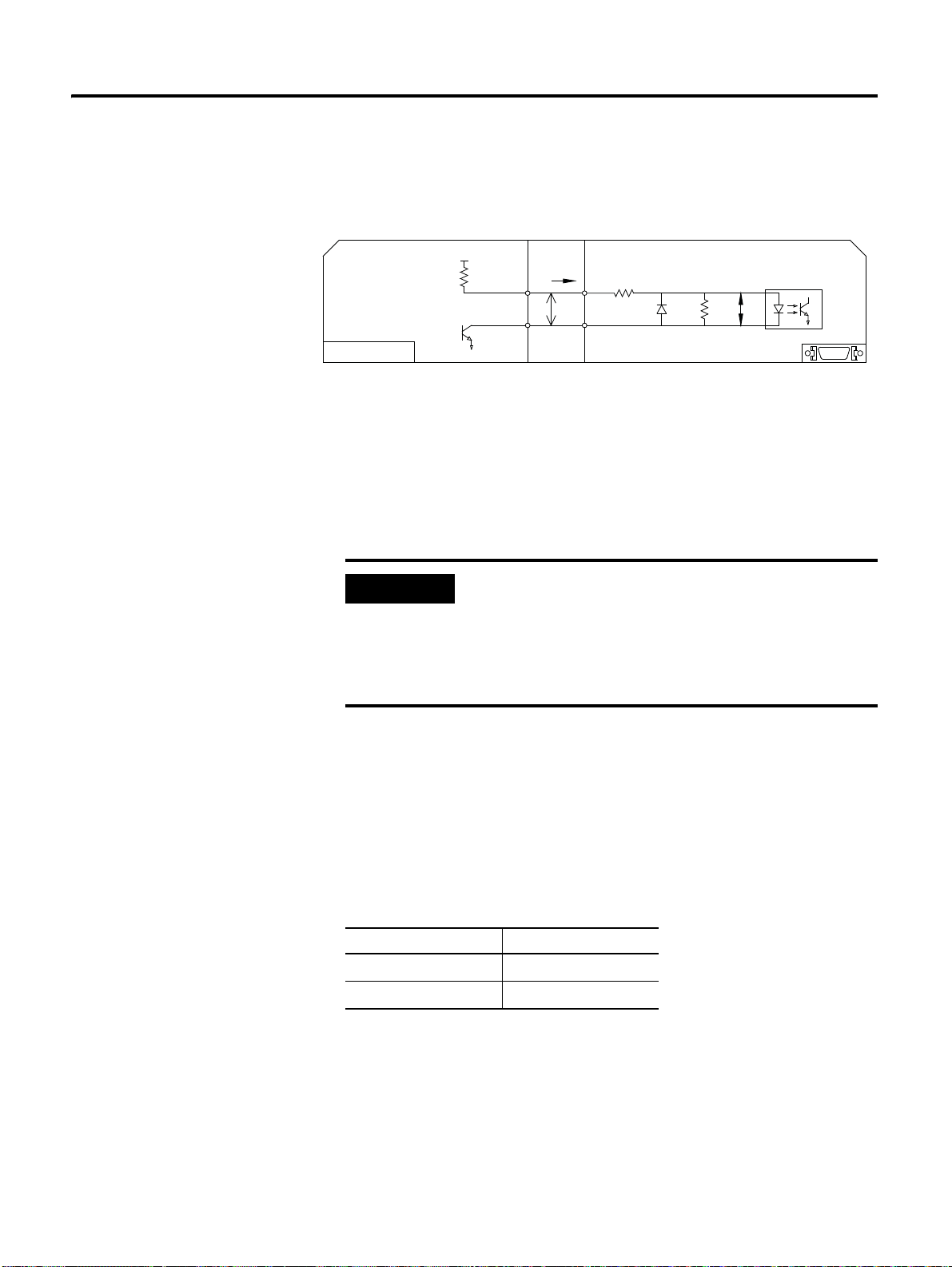
Function for Control Mode 5-13
Open Collector
Host
P
2 1
VF = 1.5 ~ 1.8
I/O
Vcc
R1
TR1
VF
i
IMPORTANT
When It is Open Collector Output
Maximum allowable frequency: 250 [kpps]
- 5 [V], 12 [V] open collectors, connect the external resistance R1 in the middle
of the general line drive input (Pin No. 11, 12, 13, and 14).
- For the 24 [V] open collector, directly connect it to Pulse (Pin No. 49, 12)
Sign (Pin No. 25, 14) without the pull up resistance R1.
Caution is needed on the highest allowed frequency. (When
the duty ratio for Pulse is 50:50).
• For the general line drive input: 900 [kpps]
• For the high-speed line drive input: 3 [Mpps]
• For the open collector input: 250 [kpps]
Cautions
In the figure above, when it is open collector method and TR1 of host
controller is ON, the servo drive identifies as low level input logic and if TR1 is
OFF, the servo drive identifies as high level input logic.
In addition, set the Pull Up resistor R1 value to be within 7 [mA] to 15 [mA] by
referring to the application example below.
Vcc of Host Controller R1
12 [V] ± 5 [%]
5 [V] ± 5 [%]
1.2 [kΩ ]
270 [Ω ]
13 CSD5 Servo Drive
Page 98

5-14 Function for Control Mode
TIP
• When you use open collector method for the output of
host controller, it is recommended to use 24 [V] for
Vcc. In doing so, the operation is stable even in the
environment with serious noise problem..
• When input voltage of 12, 14, 16and 24 of I/O is not
exactly low level (less than 0.6 [V]) or R1 value is higher
than the suggested value, an error can occur. Therefore,
use 24 [V] for Vcc of the host controller.
• Position command wiring length
– Line Drive : 5 [m] or less
– Open Collector: 1 [m] or less
CSD5 Servo Drive
Page 99

Function for Control Mode 5-15
IMPORTANT
Set the Position Command Pulse Type for the Host Controller.
Refer to table below to set position command pulse of host controller.
Parameter
Parameter Name Position Command Plulse Input Selection
Setting Value
Initial Value 0
Applicable Mode F
Others Servo-OFF > Setting > End
• 0: Use the line drive ouput of the host contoller
• 1: Use the open collector ouput of the host controller
• 2 : Use the high speed line drive output of the host contorller
Maximum allowable frequency of pulse command of host
controller is
• For the general line drive: 900 [kpps]
• For the high-speed line drive: 3 [Mpps]
• For the open collector: 250 [kpps]
If it exceeds the maximum allowable frequency, excessive
position command pulse [E.OvPUL] alarm occurs. Please
be careful not to exceed the maximum allowable frequency.
Position Command Pulse Setting
The position command supports 10 types as shown below. Check the
applicable specification with reference to electric specification of the
command pulse. If the electric specification such as timing is not appropriate, a
position error can occur.
Parameter
Parameter Name Position Command Pulse From Selection
15 CSD5 Servo Drive
Settomg Value 0 ~ 6 : Refer to the table below
Initial Value 0
Applicable Mode F
Others Servo-OFF > Setting > End
Page 100

5-16 Function for Control Mode
"L"
PULS
SIGN
PULS
SIGN
"L"
"H "
PULS
SIGN
PULS
SIGN
"L"
PULS
SIGN
PULS
SIGN
PULS
SIGN
"H "
PULS
SIGN
"H "
"L"
PULS
SIGN
"H "
PULS
SIGN
TIP
Setting
Value
Logic Command
Pulse Form
Forward Direction Operation Reverse Direction Operation Input
Muliplicat
ion
0 Positive
CW + CCW -
Logic
2 Pulse Train+
-
Sign
4 Phase A+ Phase
5 Duple
B
1
6 Quadruple
1 Negative
CW + CCW -
Logic
3 Pulse Train+
-
Sign
You can verify the data related to the position through
monitor mode in the 7-52 page "Monitor Mode Function".
CSD5 Servo Drive
 Loading...