

Page 1
Instruction Leaflet
RS stock no. 312-353, 312-369
Issued April 1997 7798
Programmable
Counter/Timer
A range of solid-state counter/timers for industrial control applications
in manufacturing, packaging and materials handling, also process
timing and monitoring functions. Made in Japan.
● Easy to programme
● Four timer or counter modes
● Wide range of supply voltages
● Choice of a.c. or d.c.operation
● 6-digit LCD display
● Non-significant zeros suppressed
● Up or down counting to 106operations
● Timing from 0.01s to 105hrs
● 4 output, 3 input modes
● Manual and remote reset facilities
● Memory back-up via internal batter y
● Time integrating facility
● Standard DIN 48 case
● 11-pin relay base
● DIN-rail,surface mounting or panel mounting hardware available
● UL and CSA approved
Dimensions
RS stock no. 312-353 Voltage range: 24 to 240V a.c.
Omron reference:H8CA - SAL
RS stock no. 312-369 Voltage range: 12 to 120V d.c.
Omron reference:H8CA - SDHS
Accessories
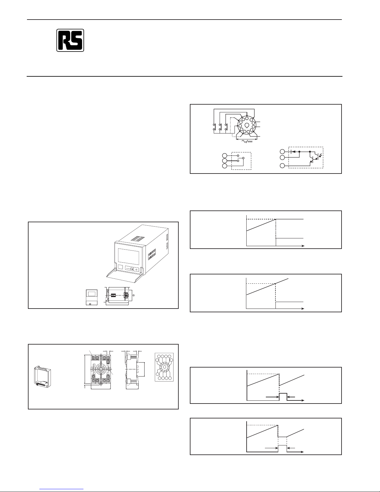
Connections
1. ME* - enables selection timer/counter mode
2. Supply
3. Input common
4. TC* - inhibits timer operation during supply failure
5. CP2 - see timer/counter input modes
6. CP1 - see timer/counter inputs modes
7. R - resets the timer/counter and turns the output off
8. See diagram (below)
9. See diagram (below)
10. Supply
11. See diagram (below)
Counter
Operating mode N
The display increments when an input is received. On reaching the set
value the output is turned on and the display is held.This continues until
a reset is applied.
Operating mode F
Operation is for mode N except that when the set value is reached the
display continues to increment.
Operating mode C
The display increments until the set value is reached. At this point the
output is turned on for a period of approx.0.5sec., the counter is reset,
and begins to count again.
Note: In this mode the unit should not be used in such a way that the
set value is reached during the timed output.
Operation is as for mode C except that the count is held at zero during
the timed output period.
Operating mode R
Input mode A CP1 count input: counter increments or decrements
when input is closed.
CP2 count direction:CP2 OFF gives count up: CP2 ON
gives count down.
Input mode B CP1 count input: counter increments when input
0.5s
48
COUNTER/TIMER
0
RST
WRITE
63.7
0.7
13.6
44.8
78
86
6
8
Warning: This product contains a 3V
lithium polycarbon monofluoride type battery which
must not be charged, cut open,
disposed of in a fire, or
subjected to direct mechanical
shock.
RS stock no.342-922
Panel mounting adaptor
Omron reference:Y92F-30
RS stock no.342-922
DIN rail/surface-mounting screw terminal with 11-pin
socket base.
Omron reference:Y92F-30
R
CP1
T.C.
M.E.
a.c. type RS stock no. 312-353
set
Figure 1
display
output
count
set
Figure 2
display
output
count
d.c. type RS stock no. 312-369
* Link ME (1-3) is only required during
installation
Link TC (4-3) is an option in the timer
mode only. Do not link in counter mode.
CP2
set
Figure 3
display
output count
set
Figure 4
display
output count
8
9
11
5
4
3
2
6
7
8
9
10
1
11
8
9
11
11.M3.5 x 7.5
70
max
7.8 3 4.5
¯ 4.5
2 1 11 10
35.4
4
5 6 7 8
31 max50 max
93
0.5s
Page 2
Input mode C CP1, CP2 Quadrature inputs from shaft encoder or
similar. If CP1 leads CP2 then counter increments; if
CP2 leads CP1 then counter decrements.
Note: Link TC should not be connected when in counter mode.
Timer
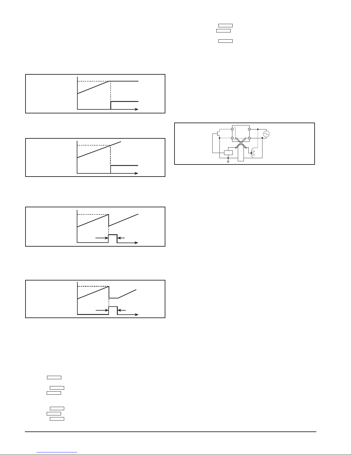
Operating mode N
The display shows the elapsed time until the set time is reached. At this
point the output is turned on the display is held. This continues until a
reset is applied.
Operating mode F
Operation is for mode N except that the display continues to show the
elapsed time when the set time is reached.
Operating mode C
The display shows the elapsed time until the set time is reached. At this
point the output is turned on for 0.5sec., the timer is reset, and timing
begins again immediately.
Note: In this mode the unit should not be used in such a way that the set
time is reached during the timed output period.
Operating mode R
Operation is as for mode C except that the timer is held in reset until the
timed output has elapsed.
CP1 Initiates a timing sequence when the input is turned on. For single
operations only, a single pulse is required. In modes C and R a
continuous input will cause cyclic operation.
CP2 Gates the timing.When this input is on, the timing is suspended.
TC This input controls the timing action during power supply failure. If
TC is on (connected to terminal 3) timing is suspended during
power failure; if TC is off, timing will continue regardless of the
power supply.
Setting up
1. Link terminal 1 to terminal 3
2. Use the key to stop through the modes i.e. counter or timer
functions; hours,min, sec, are timer functions
3. Press the key to store the displayed mode
4. Use the key to step through the input modes A,B, and C.
Note: Where the timer was pre viously selected,the display will show ‘T’
and no other mode will be possible
5. Press the key to store the display mode
6. Use the key to step through the output modes N,F, C and R
7. Press the key to store the display mode
8. Disconnect terminal 1 from terminal 3
Set point1. Ensure terminal 1 is disconnected from terminal 3
2. Press the key
3. Use the key to select the desired value for most
significant digit
4. Press the key
5. Repeat steps 3 and 4 for each digit
Application notes
1. The timer can be gated through CP2, with CP1 serving as a tr igger
input, to perform a time integrating function.
2. This unit uses a transformerless power supply and inputs may
therefore be at high potential. Extreme personal care should be
exercised when connecting external components.Where possible an
isolating transformer or low voltage supply should be used when
connecting to low voltage switching devices or sensors. Ensure any
devices connected to these input terminals have an insulation
appropriate to the power supply voltage.
3. The inter nal circuit will be destroyed when either of the two mistakes
indicated on the right figure are made. An isolating transformer is
necessary, and the input should not be earthed.
4. Programming can take with power on or off.If you have the option we
suggest power off.
5. Shor ting link between 3 & 4 with TIMER function will halt the “time
out”. Terminals 3 & 4 should be open for COUNTER function.
Technical specification
Count range: ____________________________0-999999 counts
Time ranges:______________________________0.9999.99 secs
0-99999.9 mins
0-99999.9 hours
RS stock no. 312-353 312-369
Supply voltages: 24-240V a.c. 12-120V d.c.
Supply voltage range: 90% to 110% of rated voltage
Power consumption: 1.3VA at 240V 1W at 120V
Inrush current (0.5ms) 3.7A 2.3A
Supply frequency range: 50/60Hz Supply ripple factor: - 20% max.
Count speed: 30Hz 1kHz
Pulse width, min: 16.7ms 0.5ms
Short circuit impedance: 10k½ max. (inputs 5,6,7) s/c current: 1mA
max.
Short circuit residual
voltage:__________________________________0.5V max. (inputs 5,6,7)
Open circuit impedance: ______500k½ min. (inputs 5,6,7) o/c voltage:
20V max.
Reset time: __________________________________________20ms min
Repeat accuracy: __________________________+0.05% ± 0.005 secs.
Setting error: ______________________________± 0.1% ± 0.005 secs.
Service life
- mechanical:____________________________________107operations
- electrical:__________________________106 operations at rated load
Output ratings: __________________RS stock no. 312-353: relay output,
3A resistor (SPCO)
RS stock no. 312-369:open collector
transistor,100mA at 30V (SPNO)
Ambient working temperature: ____________________-10˚C to +55˚C
Ambient storage temperature______________________-25˚C to +65˚C
Weight __________________________________________________112g
➞
+
➞
➞
+
➞
+
➞
+
set
Figure 7
display
output
time
set
Figure 8
display
output
time
set
Figure 5
display
output
time
set
Figure 6
display
output
time
Circuit
Power
Auto-transformer
Rectifier
circuit
The information provided in RS technical literature is believed to be accurate and reliable; however, RS Components assumes no responsibility for inaccuracies or
omissions, or for the use of this infor mation, and all use of such information shall be entirely at the user’s own risk.
No responsibility is assumed by RS Components for any infringements of patents or other rights of third parties which may result from its use.
7798
0.5s
0.5s
 Loading...