

Page 1

Instruction Manual
Digital & Variable Heat Guns
DE FR IT ES
EN
RS Stock No. 137-159
137-165
137-193
137-187
137-200
137-216
United Kingdon:
RS Componenets UK
PO Box 99, Corby,
Northants,
NN17 9RS
Tel: 01536 201234
Fax: 01536 405678
rswww.com
Deutschland:
RS Componenets GmbH
Hessenring 13b
64546 Morfelden-Walldorf
telefon: 06105/401-0
Fax: 06105/401-100
www.rsonline.de
This instrument is warranted to the original purchaser against defects in material and workmanship for one year from the date of purchase.
During this warranty period, RS Components will, at its option, replace or repair the defective unit, subject to verication of the defect or
its malfunction. This warranty does not cover disposable batteries, fuses or damage from abuse, neglect, accident or unauthorized repair,
alteration, contamination or abnormal conditions of operation or handling.
Any implied warranties arising out of the sale of this product, including but not limited to implied warranties of merchantability and tness
for a particular purpose, are limited to the above. RS Components shall not be liable for loss of use of the instrument or other incidental or
consequential damages, expenses, or economic loss, or for any claim or claims for such damage, expense or economic loss. Some states
or countries laws vary, so the above limitations or exclusions may not apply to you. For full terms and conditions, please refer to the latest
RS catalogue.
Espana:
RS Amidata SA
parque Empresarial Urbis Center
Avda de Europa 19 - Edicio 3
28224 Pozuelo de Alarcon
Madrid
Espana
Tel: (34) 902 10 07 11
www.amidata.es
Italia:
RS Components SpA
Via M.V.De Vizzi 93/95
20099 Cinisello Balsamo (Mi)
Tel: +39 02 66058.1
Fax: +39 02 66058.051
www.rs-components.it
Francais:
Radiospares Componenets SNC
Rue Norman KIng
BP453
F-60031 Beauvais Cedex
France
Tel: (33) 3 44 10 1500
Fax: (33) 3 44 10 1507
http://www.radiospares.fr
© Copyright 2009, LINEARTOOLS, E&OE
Page 2

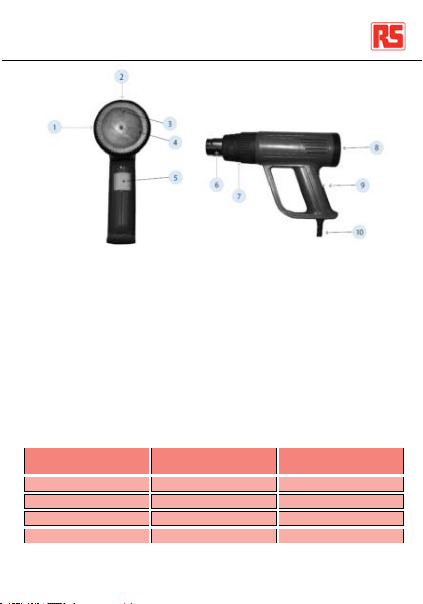
Digital Heat Guns / UK
1. Digital Display Panel
2 Flashing Temperature Indicating Arrows
3 Temperature Setting Toggle
4 4 Position Power / Airow Switch
5 3 Marked Airow Positions
6 Metal Airow Nozzle
7 Sleeve Guard (detachable)
8 Vertical Stand Surface
9 4 Position Power / Airow Switch
10 Power Cable
11 Soft grip Handle
Switch Position
O
I
II
III
2
Airow l/min
Off
300
300
550
Temperature Deg. “C”
Off
50 Constant
60-600
60-600
06/05/2009 Version No. 1
Page 3

Digital Heat Guns / UK
Operating Instructions
Select switch position I, II or III for the required airow and temperature output.
For positions II and III the temperature can be set by using the Temperature Setting Toggle (3)
Press the Toggle on the right hand side (+) to increase the temperature in 10 degree steps.
The digital display will initially indicate the target temperature and will then revert to the
current output temperature at the nozzle. Indicating arrows (2) will ash during the build up
and will stop when the target temperature is reached.
The nozzle temperature can also be reduced in 10-degree steps by pressing the left hand
side of the toggle (-); the same ashing indicators will be seen until the new target
temperature is achieved.
To turn the Heat Gun off it is recommended that it should be set to switch position I if it has
been used in switch position II or III at the higher operating temperatures. This allows the
element to cool prior to the nal switching off and will prolong the life of the heating element.
To allow the Heat Gun to cool correctly, place in its self-standing vertical position on a at,
non-slip, stable surface away from children and people who may be unaware it could be hot
Code
137-165
137-193
137-159
Code
137-165
137-193
137-159
06/05/2009 Version No. 1
Digital Heat Gun
Digital Heat Gun
Digital Heat Gun
Airow
L/min
300-550
300-550
300-550
Description
Power
W
2000
1500
2000
Voltage
240 V
110 V
230 V
BS 1363/A - 3 plug 13 A -250 V
EN 60309-3 plug 16 A–4 h 100–130 V
Schuko - 2 plug 16A - 250 V
Hz
50
50
50
Plug
Temperature
Range
50-600
50-600
50-600
Weight
750g
750g
750g
3
Page 4

Variable Heat Guns / UK
1. Rotating Temperature Setting Ring
2 “Arrow Head” Temperature Setting Position
3 “L” Low Temperature Setting
4 “H” High Temperature Setting
5 4 Position Power / Airow Switch
6 Metal Airow Nozzle
7 Heat Guard (detachable)
8 Vertical Stand Surface
9 4 Position Power / Airow Switch
10 Power Cable
Switch Position
O
I
II
III
4
Airow l/min
Off
300
300
550
Temperature Deg. “C”
Off
60 Constant
60-600
60-600
06/05/2009 Version No. 1
Page 5

Variable Heat Guns / UK
Operating Instructions
Select switch position I, II or III for the required airow and temperature output.
For positions II and III the temperature can be set by rotating the Temperature Setting
Ring (1)
With “L” in the vertical position adjacent to the “Arrow Head” the output temperature will be
at its lowest ie. 60 degrees “C”
Rotate the Temperature Setting Ring (1) in a clockwise direction to increase the
temperature.
Maximum temperature of 600 degrees “C” is achieved by fully rotating the Temperature
Setting Ring in a clockwise direction until “H” is adjacent to the “Arrow Head”
To turn the Heat Gun off it is recommended that it should be set to switch position I if it has
been used in switch position II or III at the higher operating temperatures. This allows the
element to cool prior to the nal switching off and will prolong the life of the heating element.
To allow the Heat Gun to cool correctly, place in its free-standing vertical position on a at,
non-slip, stable surface away from children and people who may be unaware it could be hot
Code
137-200
137-216
137-187
Code
137-200
137-216
137-187
06/05/2009 Version No. 1
Variable Heat Gun
Variable Heat Gun
Variable Heat Gun
Airow
L/min
300-550
300-550
300-550
Description
Power
W
2000
1500
2000
Voltage
240 V
110 V
230 V
BS 1363/A - 3 plug 13 A -250 V
EN 60309-3 plug 16 A–4 h 100–130 V
Schuko - 2 plug 16A - 250 V
Hz
50
50
50
Plug
Temperature
Range
60-600
60-600
60-600
Weight
750g
750g
750g
5
Page 6

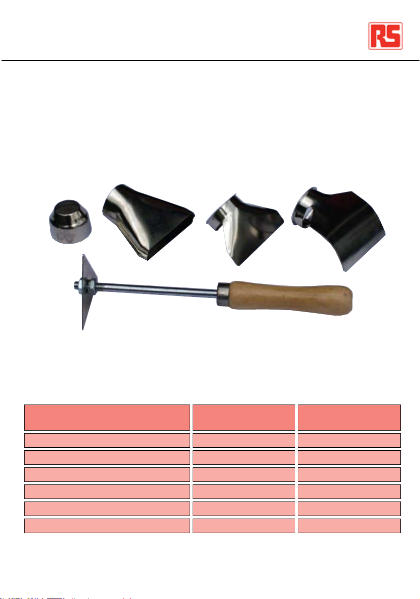
Heat Gun Accessories / UK
1 - Reduction Nozzle 22mm diameter
2 - Window Nozzle 65mm long x 15mm wide
3 - Surface Nozzle 75mm wide
4 - Reector Nozzle 70mm wide
5 - Triangular Scraper: Blade 3 sides 60mm long, overall length 225mm
1
5
Application
Paint Stripping
Electric Cable Shrink Tubing
Forming PVC Tubing
2
3
4
Nozzle Type
1, 2 or 3
4
4
Possible
Heat Range
500-600C
250-300C
250-300C
Barbeque Lighting
Water Pipe Thawing
Plastic Sheet Joining
6
Not required or 1
Not required
3
500-600C
250-300C
300-400C
06/05/2009 Version No. 1
Page 7

Heat Gun Safety Information / UK
Please read and follow these instructions when using the Heat Gun.
Failure to follow these instructions may result in the tool becoming an unnecessary source of
danger and may cause personal injury.
The Heat Gun should not be used when the tool is wet or damp or in a wet or damp
atmosphere
Do not use the tool in the rain
Do not use the tool in the presence of an explosive atmosphere
Take care when using the tool near ammable materials and ensure that hot air is not
directed for too long in the same spot.
Ensure that you are aware of ammable materials, which may be out of sight and may be
affected indirectly by conducted heat.
Plastic, Paint, Varnish and similar materials can emit toxic gases when heated. Ensure that
the area is well ventilated when working with these materials and suitable protective
equipment is worn.
Do not allow the power cord to come in contact with heat, oil, corrosive materials or sharp
edges.
Do not unplug or carry the tool by its power cord.
When using the Heat Gun in its self-standing vertical position, ensure that it is sitting on a
at; non-slip, clean, stable surface and the power cable cannot be accidentally snagged.
Accessories should only be tted to the Heat Gun nozzle when the tool is cold.
Take care when changing these accessories.
Following use allow the tool to cool completely as per the instructions before replacing in its
case.
Store the tool in a dry secure location and out of the reach of children.
Please keep these Instructions and Safety Warnings in a safe place
06/05/2009 Version No. 1
7
Page 8

Digitale Heißluftpistolen / DE
1. Digitalanzeige
2 Blinkende Pfeile zur Temperaturanzeige
3 Kippschalter zur Temperatureinstellung
4 Leistungs-/Luftstrom-Schalter mit 4 Positionen
5 3 markierte Luftstrom-Positionen
6 Luftstrom-Metalldüse
7 Griffschutz (abnehmbar)
8 Vertikale Standäche
9 Leistungs-/Luftstrom-Schalter mit 4 Positionen
10 Netzkabel
11 Weicher Griff
Schalterposition
O
I
II
III
8
Luftstrom l/min
Aus
300
300
550
Temperatur Grad „C”
Aus
50 konstant
60-600
60-600
06/05/2009 Version No. 1
Page 9

Digitale Heißluftpistolen / DE
Bedienungsanleitung
Wählen Sie Schalterposition I, II oder III, um Luftstrom und Temperaturabgabe nach Wunsch
einzustellen.
Bei den Positionen II und III kann die Temperatur mit dem Kippschalter zur Temperatureinstellung (3) eingestellt werden.
Drücken Sie auf die rechte Seite des Kippschalters (+), um die Temperatur in Schritten zu 10
Grad zu erhöhen.
Die Digitalanzeige gibt anfänglich die Zieltemperatur an und kehrt danach zur Anzeige der
C
aktuellen Ausgabetemperatur an der Düse zurück. Die Anzeigepfeile (2) blinken, während die
Temperatur steigt. Sobald die Zieltemperatur erreicht wird, hört das Blinken auf.
Die Düsentemperatur kann in Schritten zu 10 Grad gesenkt werden, indem auf die linke Seite
des Kippschalters gedrückt wird (-). Auch hier blinken dieselben Anzeigepfeile, bis die neue
Zieltemperatur erreicht wird.
Zum Ausschalten der Heißluftpistole wird empfohlen, dass sie auf Schalterposition I
eingestellt wird, wenn sie in Schalterposition II oder III bei den höheren
Betriebs-temperaturen verwendet wurde. Dadurch kann das Element abkühlen, bevor es
endgültig ausgeschaltet wird, was die Lebensdauer des Heizelements verlängert.
Damit die Heißluftpistole richtig abkühlen kann, stellen Sie diese in der vertikalen Position ab,
in der sie ihre Ausrichtung automatisch beibehält. Die Oberäche muss eben, rutschfest und
stabil sein. Zudem muss sichergestellt werden, dass weder Kinder noch Personen
Zugang zur Heißluftpistole haben, die sich möglicherweise nicht über die hohen
Temperaturen im Klaren sind.
Code
Beschreibung
Spannung
Hz
Temperat-urbereich
137-165
137-193
137-159
Code
137-165
137-193
137-159
06/05/2009 Version No. 1
Digitale Heißluftpistole
Digitale Heißluftpistole
Digitale Heißluftpistole
Luftd-urchsatz
l/min
300-550
300-550
300-550
Leist-ung
W
2000
1500
2000
240 V
110 V
230 V
BS 1363/A - 3 polig 13 A -250 V
EN 60309-3 polig 16 A–4 h 100–130 V
Schuko - 2 polig 16A - 250 V
50
50
50
Stecker
50-600
50-600
50-600
Gewicht
750g
750g
750g
9
Page 10

Einstellbare Heißluftpistole / DE
1. Drehring zur Temperatureinstellung
2 Pfeilspitzen-Temperatureinstellposition
3 “L”-Niedertemperatureinstellung
4 “H”-Hochtemperatureinstellung
5 Leistungs-/Luftstrom-Schalter mit 4 Positionen
6 Luftstrom-Metalldüse
7 Hitzeschutz (abnehmbar)
8 Vertikale Standäche
9 Leistungs-/Luftstrom-Schalter mit 4 Positionen
10 Netzkabel
10
Schalterposition
O
I
II
III
Luftstrom l/min
Aus
300
300
550
Temperatur Grad “C”
Aus
60 konstant
60-600
60-600
06/05/2009 Version No. 1
Page 11

Einstellbare Heißluftpistole / DE
Bedienungsanleitung
Wählen Sie Schalterposition I, II oder III, um Luftstrom und Temperaturabgabe nach Wunsch
einzustellen.
Bei den Positionen II und III kann die Temperatur durch Drehen des Temperatur-einstellrings
(1) eingestellt werden.
Wenn sich “L” in der vertikalen Position neben der Pfeilspitze bendet, erreicht die
Temperaturabgabe den niedrigsten Wert, also 60 °C.
Drehen Sie den Temperatureinstellring (1) im Uhrzeigersinn, um die Temperatur zu erhöhen.
Die Höchsttemperatur von 600 °C wird erreicht, indem der Temperatureinstellring
vollständig im Uhrzeigersinn gedreht wird, bis sich “H” neben der Pfeilspitze bendet.
Zum Ausschalten der Heißluftpistole wird empfohlen, dass sie auf Schalterposition I
eingestellt wird, wenn sie in Schalterposition II oder III bei den höheren
Betriebs-temperaturen verwendet wurde. Dadurch kann das Element abkühlen, bevor es
endgültig ausgeschaltet wird, was die Lebensdauer des Heizelements verlängert.
Damit die Heißluftpistole richtig abkühlen kann, stellen Sie diese in der vertikalen Position
ab, in der sie ihre Ausrichtung automatisch beibehält. Die Oberäche muss eben, rutschfest
und stabil sein. Zudem muss sichergestellt werden, dass weder Kinder noch Personen
Zugang zur Heißluftpistole haben, die sich möglicherweise nicht über die hohen
Temperaturen im Klaren sind.
Code
137-200
137-216
137-187
Code
137-200
137-216
137-187
06/05/2009 Version No. 1
Einstellbare Heißluftpistole
Einstellbare Heißluftpistole
Einstellbare Heißluftpistole
Luftd-urchsatz
l/min
300-550
300-550
300-550
Beschreibung
Leist-ung
W
2000
1500
2000
Spannung
240 V
110 V
230 V
BS 1363/A - 3 polig 13 A -250 V
EN 60309-3 polig 16 A–4 h 100–130 V
Schuko - 2 polig 16A - 250 V
Hz
50
50
50
Stecker
Temperat-urbereich
60-600
60-600
60-600
Gewicht
750g
750g
750g
11
Page 12

Zubehör für Heißluftpistole / DE
1 - Reduzierdüse (Durchmesser 22 mm)
2 - Fensterdüse 65 mm lang x 15 mm breit
3 - Oberächendüse 75 mm breit
4 - Reektordüse 70 mm breit
5 - Dreieck-Entgrater: Klinge mit 3 Seiten, je 60 mm lang, Gesamtlänge 225 mm
2
1
5
Anwendung
Lackentfernung
Schrumpfschlauch für Elektrokabel
Formen von PVC-Rohren
3
Düsentyp
1, 2 oder 3
4
4
4
Möglicher
Temperaturbereich
500-600C
250-300C
250-300C
Anzünden von Grills
Auftauen von Wasserleitungen
Zusammenfügen von Kunststoffplatten
12
Nicht erforderlich oder 1
Nicht erforderlich
3
500-600C
250-300C
300-400C
06/05/2009 Version No. 1
Page 13

Sicherheitshinweise zur Heißluftpistole / DE
Bitte lesen Sie die folgenden Anweisungen durch, und befolgen Sie sie beim Verwenden der
Heißluftpistole.
Wenn diese Anweisungen nicht befolgt werden, kann das Werkzeug unnötige Gefahren und
möglicherweise sogar Verletzungen verursachen.
Die Heißluftpistole sollte nicht verwendet werden, wenn das Werkzeug nass oder feucht ist
oder sich in einer nassen oder feuchten Umgebung bendet.
Verwenden Sie das Werkzeug nicht im Regen.
Verwenden Sie das Werkzeug nicht bei Vorhandensein einer explosionsgefährdeten
Umgebung.
Gehen Sie vorsichtig vor, wenn Sie das Werkzeug in der Nähe von entammbaren
Materialien verwenden, und stellen Sie sicher, dass die Heißluft nicht zu lang auf dieselbe
Stelle gerichtet ist.
Achten Sie immer auf entammbare Materialien, die sich möglicherweise außerhalb des
Blickfelds benden und indirekt durch Wärmeleitung beeinträchtigt werden.
Kunststoff, Lack, Firnis und ähnliche Materialien können beim Erhitzen toxische Gase
abgeben. Vergewissern Sie sich, dass der Bereich beim Arbeiten mit diesen Materialien gut
belüftet ist und dass geeignete Schutzausrüstung getragen wird.
Vermeiden Sie den Kontakt des Netzkabels mit Hitze, Öl, korrosiven Materialien oder
scharfen Kanten.
Sie dürfen das Werkzeug nicht durch Ziehen am Netzkabel ausstecken oder transportieren.
Wenn die Heißluftpistole in der vertikalen Position verwendet wird, in der sie ihre
Ausrichtung automatisch beibehält, müssen Sie sicherstellen, dass sie auf einer ebenen,
rutschfesten, sauberen und stabilen Oberäche platziert ist und dass das Netzkabel nicht
versehentlich eingeklemmt werden kann.
Zubehör sollte nur dann an der Düse der Heißluftpistole angebracht werden, wenn das
Werkzeug kalt ist. Gehen Sie beim Wechseln dieser Zubehörteile vorsichtig vor.
Lassen Sie das Werkzeug gemäß Anweisungen nach der Verwendung vollständig abkühlen,
bevor Sie es wieder in der Verpackung verstauen.
Bewahren Sie das Werkzeug an einem trockenen und sauberen Ort auf, zu dem Kinder
keinen Zugang haben.
Bewahren Sie diese Anweisungen und Sicherheitshinweise an einem sicheren Ort auf.
06/05/2009 Version No. 1
13
Page 14

Pistolets thermiques numériques / FR
1. Afchage numérique
2 Flèches d’indication de température clignotantes
3 Sélecteur de température
4 Interrupteur pour débit d’air/puissance 4 positions
5 3 marques de position pour le débit d’air
6 Buse en métal pour le débit d’air
7 Protection du manchon (amovible)
8 Surface du support vertical
9 Interrupteur pour débit d’air/puissance 4 positions
10 Cordon d’alimentation
11 Poignée adhérente renforcée
Position interrupteur
14
Débit d’air l/min
O
I
II
III
Arrêt
300
300
550
Température - Deg. C°
Arrêt
50 constants
60-600
60-600
06/05/2009 Version No. 1
Page 15

Pistolets thermiques numériques / FR
Mode d’emploi
Sélectionnez la position I, II ou III de l’interrupteur selon le débit d’air et la température de
sortie souhaités.
Pour les positions II et III, la température peut être réglée avec le sélecteur de température
(3).
Appuyez sur le côté droit du sélecteur (+) pour augmenter la température par incrément de 10
degrés.
L’afchage numérique indique d’abord la température cible, puis la température de sortie au
niveau de la buse. Les èches d’indication (2) clignotent jusqu’à ce que la température cible
soit atteinte.
Vous pouvez également diminuer la température au niveau de la buse par décrément de 10
degrés en appuyant sur le côté gauche du sélecteur (-) ; les èches d’indication clignotent
alors, jusqu’à ce que la nouvelle température cible soit atteinte.
Pour arrêter le pistolet thermique, il est recommandé de placer l’interrupteur en position I s’il
était en position II ou III et si les températures de fonctionnement maximales étaient sélection-
nées. L’outil peut ainsi refroidir avant l’arrêt nal, ce qui permet de prolonger sa durée de vie.
An que le pistolet thermique refroidisse correctement, placez-le sur son support vertical sur
une surface plane, non glissante et stable. Tenez-le éloigné des enfants et des
personnes qui n’auraient pas connaissance de son dégagement de chaleur.
Code
137-165
137-193
137-159
Code
137-165
137-193
137-159
06/05/2009 Version No. 1
Pistolet thermique numérique
Pistolet thermique numérique
Pistolet thermique numérique
Débit d’air
l/min
300-550
300-550
300-550
Description
Puissance
W
2000
1500
2000
Tension
240 V
110 V
230 V
BS 1363/A - 3 broches 13 A -250 V
EN 60309-3 broches 16A–4 h 100 130V
Schuko - 2 broches 16A - 250 V
Fréquence
50
50
50
Fiche
Plage de tempé-rature
50-600
50-600
50-600
Poids
750g
750g
750g
15
Page 16

Pistolet thermique à variateur / FR Pistolet thermique à variateur / FR
1. Anneau rotatif de sélection de température
2 Indicateur éché de sélection de température
3 Température minimale (L)
4 Température maximale (H)
5 Interrupteur pour débit d’air/puissance 4 positions
6 Buse en métal pour le débit d’air
7 Protection contre la chaleur (amovible)
8 Surface du support vertical
9 Interrupteur pour débit d’air/puissance 4 positions
10 Cordon d’alimentation
Position interrupteur
16
Débit d’air l/min
O
I
II
III
Arrêt
300
300
550
Température - Deg. C°
Arrêt
60 constants
60-600
60-600
06/05/2009 Version No. 1 06/05/2009 Version No. 1
Page 17

Mode d’emploi
Sélectionnez la position I, II ou III de l’interrupteur selon le débit d’air et la température de
sortie souhaités.
Pour les positions II et III, la température peut être réglée avec l’anneau rotatif de sélection
(1).
Lorsque le « L » est en position verticale et adjacent à l’indicateur éché, la température de
sortie sera minimale, c’est-à-dire 60 °C.
Tournez l’anneau de sélection (1) dans le sens horaire pour augmenter la température.
Pour obtenir la température maximale de 600 °C, tournez complètement l’anneau de
sélection dans le sens horaire jusqu’à ce que le « H » soit adjacent à l’indicateur éché.
Pour arrêter le pistolet thermique, il est recommandé de placer l’interrupteur en position I s’il
était en position II ou III et si les températures de fonctionnement maximales étaient sélec-
tionnées. L’outil peut ainsi refroidir avant l’arrêt nal, ce qui permet de prolonger sa durée de
vie.
An que le pistolet thermique refroidisse correctement, placez-le sur son support vertical sur
une surface plane, non glissante et stable. Tenez-le éloigné des enfants et des
personnes qui n’auraient pas connaissance de son dégagement de chaleur.
Code
137-200
137-216
137-187
Code
137-200
137-216
137-187
Description
Pistolet thermique à variateur
Pistolet thermique à variateur
Pistolet thermique à variateur
Débit d’air
l/min
300-550
300-550
300-550
Puissance
W
2000
1500
2000
Tension
240 V
110 V
230 V
BS 1363/A - 3 pines 13 A -250 V
EN 60309 - 3 pines 16 A – 4 h 100 – 130
Schuko - 2 pines 16A - 250 V
Fréquence
50
50
50
Fiche
Plage de tempé-rature
60-600
60-600
60-600
Poids
750g
750g
750g
17
Page 18

Accessoires du pistolet thermique / FR
1 - Buse de réduction 22 mm de diamètre
2 - Buse à fente 65 mm x 15 mm (L x l)
3 - Buse de surface largeur 75 mm
4 - Buse réectrice largeur 70 mm
5 - Racloir triangulaire : lame 3 côtés longueur 60 mm, longueur totale 225 mm
2
1
5
Application
Décapage peinture
Gaines électriques thermorétractables
Modelage gaines PVC
3
Type de buse
1, , 2 ou 3
4
4
4
Plage de température
possible
500-600C
250-300C
250-300C
Allumage barbecue
Réchauffage conduites d’eau gelées
Soudage toiles plastique
18
Non requis ou 1
Non requis
3
500-600C
250-300C
300-400C
06/05/2009 Version No. 1
Page 19

Informations relatives à la sécurité - Pistolet thermique / FR
Lisez les instructions ci-dessous et respectez-les lors de l’utilisation du pistolet
thermique. En cas de non-respect de ces instructions, l’outil pourrait représenter
une source de danger inutile et entraîner des blessures.
N’utilisez pas le pistolet thermique s’il est mouillé ou humide, ou s’il se trouve dans
un environnement humide. N’utilisez pas l’outil sous la pluie.
N’utilisez pas l’outil dans un environnement présentant un risque d’explosion.
Utilisez l’outil avec précaution à proximité de matières inammables et assurez-
vous que l’air chaud n’est pas orienté trop longtemps vers le même endroit.
Assurez-vous que vous avez connaissance de la présence de matières
inammables, qui peuvent ne pas être visibles et risquent d’être affectées
indirectement par la chaleur conduite.
Le plastique, la peinture, les vernis et d’autres matières similaires peuvent émettre
des gaz toxiques sous l’effet de la chaleur. Assurez-vous que la zone est
correctement aérée lors de l’utilisation de ces matières et portez un équipement de
protection adapté.
Tenez le cordon d’alimentation éloigné de la chaleur, des lubriants, des matières
corrosives ou des bords tranchants.
Ne débranchez pas l’outil en tirant sur le cordon d’alimentation et ne le portez pas
par ce cordon.
Lors de l’utilisation du pistolet thermique placé sur son support vertical,
assurez-vous que la surface sur laquelle il se trouve est plane, non glissante,
propre et stable. Le passage du cordon d’alimentation ne doit pas non plus être
entravé par inadvertance.
Ne placez les accessoires sur la buse du pistolet thermique que lorsque l’outil est
froid. Soyez vigilant lorsque vous changez d’accessoire.
Après avoir utilisé l’outil, laissez-le refroidir complètement, conformément aux
instructions, avant de le remettre dans le boîtier.
Rangez l’outil dans un endroit sécurisé, sec et hors de portée des enfants.
Conservez soigneusement ces instructions et informations relatives à la sécurité.
06/05/2009 Version No. 1
19
Page 20

Pistole termiche digitali / IT
1. Display digitale
2 Frecce di indicazione temperatura lampeggianti
3 Leva di impostazione temperatura
4 Interruttore di posizione/Interruttore per usso d’aria
5 3 Posizioni usso d’aria contrassegnate
6 Ugello del usso d’aria in metallo
7 Protezione manicotto (amovibile)
8 Supercie supporto verticale
9 Interruttore di posizione/Interruttore per usso d’aria
10 Cavo di alimentazione
11 Maniglia impugnatura morbida
20
Posizione
interruttore
O
I
II
III
Flusso d’aria
l/min
Off
300
300
550
Temperatura
gradi “C”
Off
50 constante
60-600
60-600
06/05/2009 Version No. 1
Page 21

Pistole termiche digitali / IT
Istruzioni d’uso
Selezionare la posizione interruttore I, II o III per regolare il usso d’aria e la temperatura
desiderata.
Per le posizioni II e III impostare la temperatura con la leva di impostazione temperatura (3)
Premere la leva sul lato destro (+) per aumentare la temperatura con incrementi di 10 gradi.
Il display digitale, all’inizio, indicherà la temperatura nale per poi tornare ad indicare l’attuale
temperatura di uscita sull’ugello. Le frecce di indicazione (2) lampeggiano nella fase di riscal-
damento e si arrestano al raggiungimento della temperatura nale impostata.
È possibile ridurre la temperatura dell’ugello in decrementi di 10 gradi premendo il lato
sinistro della leva (-); gli stessi indicatori lampeggeranno n quando viene raggiunta la nuova
temperatura nale impostata.
Per spegnere la pistola termica, si raccomanda di portare l’interruttore in posizione I se è
stata utilizzata in posizione II o III alle temperature d’esercizio più elevate. Ciò consente il raffreddamento dell’elemento prima di spegnerlo completamente garantendo una
maggiore durata dell’elemento termico.
Per consentire il corretto raffreddamento della pistola termica, posizionarla in posizione verticale senza supporto su una supercie piana, antiscivolo, stabile, fuori dalla portata dei bambini e da persone non a conoscenza che l’utensile potrebbe essere a temperatura elevata.
Codice
137-165
137-193
137-159
Codice
137-165
137-193
137-159
06/05/2009 Version No. 1
Pistola termica digitale
Pistola termica digitale
Pistola termica digitale
Flusso d’aria
l/min
300-550
300-550
300-550
Descrizione
Aliment-azione
W
2000
1500
2000
Tensione
240 V
110 V
230 V
Connettore maschio
BS 1363/A - 3 pin 13 A -250 V
EN 60309-3 pin 16 A – 4 h 100 – 130 V
Schuko - 2 pin 16A - 250 V
Hz
50
50
50
Gamma temp-eratura
50-600
50-600
50-600
Peso
750g
750g
750g
21
Page 22
Pistola termica regolabile / IT
1. Anello di impostazione temperatura girevole
2 “Punta della freccia” posizione di impostazione temperatura
3 “L” Impostazione temperatura bassa
4 “H” Impostazione temperatura alta
5 Interruttore di posizione/Interruttore per usso d’aria
6 Ugello del usso d’aria in metallo
7 Protezione termica (amovibile)
8 Supercie supporto verticale
9 Interruttore di posizione/Interruttore per usso d’aria
10 Cavo di alimentazione
Posizione interruttore
22
Flusso d’aria l/min
O
I
II
III
Off
300
300
550
Temperatura gradi “C”
Off
60 constante
60-600
60-600
06/05/2009 Version No. 1
Page 23

Pistola termica regolabile / IT
Istruzioni d’uso
Selezionare la posizione interruttore I, II o III per regolare il usso d’aria e la temperatura
desiderata.
Per le posizioni II e III, impostare la temperatura ruotando l’anello di impostazione
temperatura (1)
Con “L” in posizione verticale sulla “punta della freccia” la temperatura di uscita sarà minima,
vale a dire 60 gradi °C.
Per aumentare la temperatura, ruotare l’anello di impostazione temperatura in senso orario
(1).
Regolare la temperatura massima di 600 gradi °C ruotando completamente l’anello di
impostazione temperatura in senso orario no a posizionare “H” sulla “punta della freccia”
Per spegnere la pistola termica, si raccomanda di portare l’interruttore in posizione I se è
stata utilizzata in posizione II o III alle temperature d’esercizio più elevate. Ciò consente il
raffreddamento dell’elemento prima di spegnerlo completamente garantendo una
maggiore durata dell’elemento termico.
Per consentire il corretto raffreddamento della pistola termica, collocarla in posizione
verticale senza supporto su una supercie piana, antiscivolo, stabile, fuori dalla portata
dei bambini e da persone non a conoscenza che l’utensile potrebbe essere a temperatura
elevata
Codice
137-200
137-216
137-187
Codice
137-200
137-216
137-187
06/05/2009 Version No. 1
Pistola termica regolabile
Pistola termica regolabile
Pistola termica regolabile
Flusso d’aria
l/min
300-550
300-550
300-550
Descrizione
Aliment-azione
W
2000
1500
2000
Tensione
240 V
110 V
230 V
Connettore maschio
BS 1363/A - 3 pin 13 A -250 V
EN 60309-3 pin 16 A – 4 h 100 – 130 V
Schuko - 2 pin 16A - 250 V
Hz
50
50
50
Gamma temp-eratura
60-600
60-600
60-600
Peso
750g
750g
750g
23
Page 24
Accessori per pistola termica / IT
1 - Ugello di riduzione diametro 22 mm
2 - Ugello per nestre L x H 65 mm x 15 mm
3 - Ugello per superci largh. 75 mm
4 - Ugello per riettore largh. 70 mm
5 - Raschietto triangolare: lama a 3 lati lunghezza 60 mm, lunghezza totale 225 mm
2
1
5
Applicazione
Sverniciante
Guaina termoretraibile per cavi elettrici
Formatura tubi in PVC
3
Tipo di ugello
1, 2 ó 3
4
4
4
Gamma termica
possibile
500-600C
250-300C
250-300C
Illuminazione barbecue
Scongelamento tubazioni acqua
Unione fogli di plastica
24
Non richiesta o 1
Non richiesta
3
500-600C
250-300C
300-400C
06/05/2009 Version No. 1
Page 25

Avvertenze di sicurezza per la pistola termica / IT
Leggere ed osservare le presenti istruzioni per l’uso della pistola termica.
La mancata osservanza di queste istruzioni e l’uso inadeguato dell’utensile può
comportare eventuali danni e causare lesioni personali.
Non utilizzare la pistola termica se l’utensile è bagnato o umido o in ambienti umidi
o bagnati.
Non utilizzare l’utensile sotto la pioggia.
Non utilizzare l’utensile in ambienti a rischio di esplosione.
Prestare attenzione quando si usa l’utensile in prossimità di materiale inammabile
e accertarsi che il getto di aria calda non sia diretto sullo stesso punto troppo a
lungo.
Accertarsi dell’eventuale presenza di materiali inammabili, non a vista e che
possono essere indirettamente colpiti dal calore sprigionato.
Plastica, pittura, vernice e materiali analoghi possono emettere gas tossici se
riscaldati. Accertarsi che l’area sia adeguatamente ventilata quando si lavorano
questi materiali e indossare appositi indumenti protettivi.
Evitare che il cavo di alimentazione venga a contatto con fonti di calore, olio,
materiali corrosivi o spigoli taglienti.
Non scollegare o prendere l’utensile dal cavo di alimentazione.
Quando si utilizza la pistola termica in posizione verticale senza supporto,
accertarsi che sia posizionata su una supercie piana, antiscivolo, pulita e stabile e
che il cavo di alimentazione non rimanga incidentalmente impigliato.
Montare gli accessori sull’ugello della pistola termica solo quando la pistola è
fredda. Prestare attenzione quando si procede alla sostituzione di tali accessori.
Dopo aver utilizzato l’utensile, lasciarlo raffreddare completamente come indicato
nelle istruzioni prima di riporlo nella relativa custodia.
Conservare l’utensile in un luogo asciutto, sicuro e fuori dalla portata dei bambini.
Conservare queste istruzioni e le avvertenze per la sicurezza in un luogo sicuro.
06/05/2009 Version No. 1
25
Page 26

Decapadores por aire caliente / ES
1. Pantalla digital
2. Flechas parpadeantes que indican la temperatura
3. Tecla de ajuste de la la temperatura
4. Interruptor de 4 posiciones para potencia / caudal de aire
5. 3 posiciones marcadas para el caudal de aire
6. Boquilla de metal para caudal de aire
7. Protección del manguito (separable)
8. Supercie del soporte vertical
9. Interruptor de 4 posiciones para la potencia / caudal de aire
10. Cable de alimentación
11. Mango de agarre suave
26
Posición del
interruptor
O
I
II
III
Caudal de aire en
l/min
Apagado
300
300
550
Temperatura en
grados “C”
Apagado
50 constante
60-600
60-600
06/05/2009 Version No. 1
Page 27

Decapadores por aire caliente digitales / ES
Instrucciones de funcionamiento
Seleccione con el interruptor la posición I, II o III, según el caudal de aire y la temperatura
deseadas.
En las posiciones II y III, la temperatura se puede ajustar con la tecla de ajuste de la
temperatura (3)
Presione la parte derecha de la tecla (+) para aumentar la temperatura en pasos de 10 grados.
La pantalla digital mostrará primero la temperatura seleccionada y después regresará a la
temperatura actual de salida en la boquilla. Las echas indicadoras (2) parpadearán durante
la subida y pararán en el momento en que se alcance la temperatura.
La temperatura de la boquilla también se puede disminuir en pasos de 10 grados haciendo
presión en la parte izquierda de la tecla (-); se encenderán los mismos indicadores hasta que
se alcance la nueva temperatura deseada.
Para apagar el decapador por aire caliente, se recomienda ajustar primero en la posición I
si se ha estado utilizando en las posiciones II o III a las temperaturas más elevadas de
funcionamiento. Esto permite el enfriamiento del elemento antes de su apagado y
prolongará la vida útil del mismo.
Para permitir que el decapador por aire caliente se enfríe correctamente, colóquelo en su
posición vertical independiente sobre una supercie plana, antideslizante y estable, lejos del
alcance de los niños y de personas que no sepan que está caliente
Código
137-165
137-193
137-159
Código
137-165
137-193
137-159
06/05/2009 Version No. 1
Decapador por aire caliente
Decapador por aire caliente
Decapador por aire caliente
Caudal de aire
l/min
300-550
300-550
300-550
Descripción
Poten-cia
W
2000
1500
2000
Tensión
240 V
110 V
230 V
BS 1363/A - 3 pines 13 A -250 V
EN 60309-3 pines 16 A–4 h 10 –130 V
Schuko - 2 pines 16A - 250 V
Hz
50
50
50
Conector macho
Rango de tempe-
raturas
50-600
50-600
50-600
Peso
750g
750g
750g
27
Page 28

Decapador por aire caliente / ES
1. Anillo giratorio de ajuste de la temperatura
2. Posición de ajuste de la temperatura “punta de echa”
3. Ajuste de temperatura baja “L”
4. Ajuste de temperatura alta “H”
5. Interruptor de 4 posiciones de potencia / caudal de aire
6. Boquilla de metal para caudal de aire
7. Protección térmica (separable)
8. Supercie del soporte vertical
9. Interruptor de 4 posiciones de potencia / caudal de aire
10. Cable de alimentación
28
Posición del
interruptor
O
I
II
III
Caudal de aire en
l/min
Apagado
300
300
550
Temperatura en
grados “C”
Apagado
60 constante
60-600
60-600
06/05/2009 Version No. 1
Page 29

Decapador por aire caliente / ES
Instrucciones de funcionamiento
Seleccione con el interruptor la posición I, II o III, según el caudal de aire y la temperatura
deseadas.
En las posiciones II y III, la temperatura se puede ajustar girando el anillo de ajuste de la
temperatura (1)
Con la “L” en posición vertical junto la “punta de echa”, la temperatura de salida será la
más baja, es decir, 60 °C.
Gire el anillo de ajuste de la temperatura (1) en sentido horario para aumentar la temperatura.
Para alcanzar la temperatura máxima de 600 °C, gire completamente el anillo de ajuste de
la temperatura en sentido horario hasta que la “H” se encuentre junto a la “punta de echa”.
Para apagar el decapador por aire caliente, se recomienda ajustar primero en la posición I
si se ha estado utilizando en las posiciones II o III a las temperaturas más elevadas de
funcionamiento. Esto permite el enfriamiento del elemento antes de su apagado y
prolongará la vida útil del mismo.
Para permitir que el decapador por aire caliente se enfríe correctamente, colóquelo en su
posición vertical independiente sobre una supercie plana, antideslizante y estable, lejos del
alcance de los niños y de personas que no sepan que está caliente
Código
137-200
137-216
137-187
Código
137-200
137-216
137-187
06/05/2009 Version No. 1
Decapador por aire caliente
Decapador por aire caliente
Decapador por aire caliente
Caudal de aire
l/min
300-550
300-550
300-550
Descripción
Poten-cia
W
2000
1500
2000
Tensión
240 V
110 V
230 V
BS 1363/A - 3 pines 13 A -250 V
EN 60309-3 pines 16 A–4 h 100–130 V
Schuko - 2 pines 16A - 250 V
Hz
50
50
50
Conector macho
Rango de
tempe-raturas
60-600
60-600
60-600
Peso
750g
750g
750g
29
Page 30

Accesorios para el decapador por aire caliente / ES
1 - Boquilla reductora de 22 mm de diámetro
2 - Boquilla plana de 65 mm de largo x 15 mm de ancho
3 - Boquilla para protección de vidrios de 75 mm de ancho
4 - Boquilla reectora de 70 mm de ancho
5 - Rasqueta triangular: puntera plana de 3 lados de 60 mm de largo,
longitud total de 225 mm
2
1
5
Aplicación
Decapado de pintura
Enmanguitado de cables eléctricos
Moldeado de tubos de PVC
Tipo de
boquilla
1, 2 ó 3
4
4
3
4
Intervalo de calor
permitido
500-600C
250-300C
250-300C
Encendido de barbacoa
Descongelación de la tubería de agua
Unión de láminas de plástico
30
No necesaria o 1
No necesaria
3
500-600C
250-300C
300-400C
06/05/2009 Version No. 1
Page 31

Información de seguridad para el decapador por aire caliente / ES
Lea y siga estas instrucciones para el uso del decapador por aire caliente.
Si no se siguen estas instrucciones, la herramienta puede convertirse en un foco
de peligro innecesario y puede causar daños personales.
El decapador por aire caliente no debe utilizarse cuando esté húmedo, ni utilizarse
en un ambiente húmedo.
No utilice la herramienta bajo la lluvia.
No utilice la herramienta en un ambiente con riesgo de explosión.
Tenga cuidado si utiliza la herramienta cerca de materiales inamables y
asegúrese de no dirigir aire caliente durante un tiempo demasiado prolongado
en el mismo punto.
Compruebe los materiales inamables que puedan estar fuera del alcance de la
vista y que puedan verse afectados indirectamente por la conducción térmica.
El plástico, la pintura, el barniz y los materiales similares pueden emitir gases
tóxicos al calentarse. Compruebe que la zona esté bien ventilada al trabajar
con estos materiales y que se lleva un equipo de protección adecuado.
Evite el contacto de los cables de alimentación con el calor, aceite, materiales
corrosivos o cantos alados.
No desconecte ni transporte la herramienta sujetando sólo el cable de
alimentación.
Cuando utilice el decapador por aire caliente en su posición vertical
independiente, compruebe que se encuentra sobre una supercie plana,
antideslizante, limpia y estable, y que el cable de alimentación no esté expuesto
a tirones accidentales.
Los accesorios solamente se deberán montar cuando la boquilla del el
decapador por aire caliente esté fría. Cambie los accesorios con precaución.
Después de utilizar la herramienta, deje que se enfríe por completo, tal como
se describe en las instrucciones para la sustitución en cada caso.
Guarde la herramienta en un lugar seguro y fuera del alcance de los niños.
Guarde estas instrucciones y advertencias de seguridad en un lugar seguro.
06/05/2009 Version No. 1
31
 Loading...