

Page 1
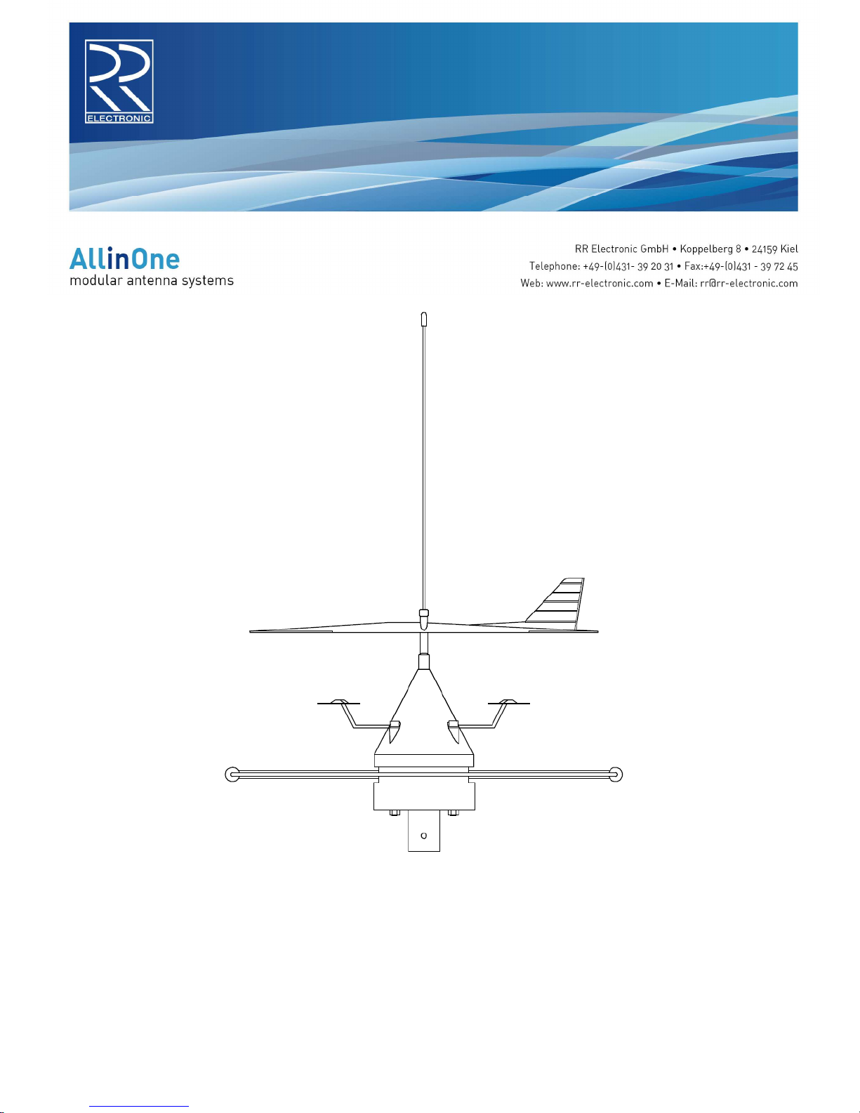
ANTIGUA
EINBAUANLEITUNG
MOUNTINGINSTRUCTIONS
Page 2
Installation der Antennenanlage ANTIGUA
Die Antennenanlage ANTIGUA besteht aus den Einzelantennen DELTA 163S und DELTA 12 M, die
zu einer Einheit zusammengesetzt montiert werden.
Antennenstandort:
Die Antennenanlage ANTIGUA sollte möglichst im Masttop installiert werden. Oberhalb der Antenne
sollten sich keine weiteren Antennen befinden.
Antennenkabel:
Als Antennenkabel sind für die Antennenanlage ANTIGUA Koaxialkabel mit 50 Ohm Wellenwiderstand
zu verwenden, vorzugsweise Aircell-7 oder Belden H2000 Flex. An der Antennenseite werden ein
BNC-Stecker für die DELTA 163S und ein N-Stecker für die DELTA 12 M verwendet. ACHTUNG!
UHF-Stecker (PL-Stecker) sind für diese Antennenanlage NICHT geeignet! Wichtig: Die Kabel
müssen mit einer Zugentlastung versehen sein! Für eventuelle Trennstellen am Mastfuß werden
BNC- und N-Stecker montiert. Die Antennenkabel sind auf möglichst kurzem Weg zum
Antennenverteiler AV 112 und zum UKW Seefunkgerät zu führen. Vor dem Anschluss sind die
Antennenkabel auf Kurzschluss zu prüfen!
Zusammenbau der Antennen:
Das Antennenkabel mit BNC-Stecker wird von unten durch das Rohr des Antennenhalters AH 12 und
durch die Öffnung in der DELTA 12 M gezogen und mit der DELTA 163S verbunden. Danach wird das
Antennenkabel mit N-Stecker durch die Öffnung im Antennenhalter AH 12 gezogen und mit der
DELTA 12 M verbunden. Schließlich werden die Antennen zusammengesetzt und mit den
Antennenhaltern verschraubt.
Wichtig: Sämtliche Metallteile der Antennen sowie die Steckverbindungen dürfen keine
elektrische Verbindung zu anderen Metallteilen des Schiffes haben, da der Kabelaußenleiter
mit dem Minuspol des Bordnetzes verbunden ist.
Der Antennenverteiler AV 112 wird unter Deck in der Nähe der anzuschließenden Geräte montiert.
Anschluss des Antennenverteilers AV 112:
Der Antennenverteiler AV 112 wird unter Deck in der Nähe der anzuschließenden Geräte montiert.
Der Anschluss „INPUT: DELTA 12 M“ wird mit der Antenne DELTA 12 M über einen N-Stecker
verbunden. Für die Anschlüsse „Output 1 und Output 2: DVB-T / T-DAB“ werden F-Steckverbinder
und 75 Ohm Kabel benötigt.
Stromversorgung:
Wichtig: Die Stromversorgung darf erst nach Abschluss sämtlicher Installationsarbeiten
eingeschaltet werden.
Die Stromversorgung sollte über einen Schalter oder Sicherungsautomaten der Schalttafel
angeschlossen werden. Wenn keines der angeschlossenen Empfangsgeräte in Betrieb ist, sollte die
Stromversorgung für die Antennenanlage ausgeschaltet werden.
Für den Betrieb des UKW-Seefunkgerätes muss die Stromversorgung der Antennenanlage
nicht eingeschaltet sein.
Die blau isolierte Stromversorgungsleitung wird mit dem Minuspol und die braun isolierte Leitung mit
dem Pluspol des 12V- oder 24V-Bordnetzes verbunden.
Die beiden Antennenkabel dürfen NIEMALS verwechselt werden - sonst können die Antenne
DELTA 12 M und / oder der Antennenverteiler AV 112 zerstört werden!
Page 3

Für eine einwandfreie Funktion der Antennenanlage ist eine fachmännische Installation
sämtlicher Verbindungen, insbesondere aller Anschlußstecker unbedingt erforderlich!
Schäden durch Nichtbeachtung dieser Hinweise sind von der Garantie ausgeschlossen.
Im Zweifelsfalle einen Fachmann zu Rate ziehen!
Fehlersuchschema für Antennenanlage ANTIGUA
1. Gesamte Antennenanlage ohne Funktion
1.1. Zuordnung der Antennenkabel zu den Antennen überprüfen, insbesondere auch an eventuell
vorhandenen Trennstellen am Mastfuß. Zum Unterscheiden der Antennen kann der
Widerstand incl. Antennenkabel mit einem Ohmmeter gemessen werden:
– DELTA 163S: Kurzschluss
– DELTA 12 M: ca. 4,7 kOhm
2. UKW Seefunk ohne Funktion
2.1. Überprüfen des Antennenkabels zur DELTA 163S, insbesondere der Steckverbinder. Beim
Prüfen des Gleichstromwiderstandes mit einem Ohmmeter wird ein Kurzschluss gemessen.
2.2. Überprüfen des Seefunkgerätes unabhängig von der Antennenanlage.
3. TV und UKW-Radio ohne Funktion
3.1. Überprüfen der Stromversorgung (auch Polarität) des AV 112 sowie der Sicherung (0,2 A 5 ×
20 mm).
3.2. Überprüfen der Steckverbinder und Verbindungen zu TV und Radio
3.3. Überprüfen der Stromaufnahme des AV 112:
– mit angeschlossener Antenne ca. 150 mA
– ohne angeschlossene Antenne ca. 115 mA
3.4. Überprüfen des Antennenkabels und der Steckverbindungen. Beim Prüfen des
Gleichstromwiderstandes mit einem Ohmmeter wird ein Widerstand von ca. 4,7 kOhm
gemessen.
3.5. Überprüfen der Ausgangsspannung vom AV 112 zur Antenne: 12 V
Wichtige Hinweise:
Starke Schatten im Fernsehbild können durch Reflektionen an Gebäuden, Kränen, etc. entstehen
durch die Rundempfangseigenschaft der Antenne. Durch den Betrieb des UKW-Seefunkgerätes kann
der Empfang der DELTA 12 M beeinträchtigt werden wegen der geringen Entfernung zur
Sendeantenne.
Reparaturen an den Antennen oder am Antennenverteiler nur vom autorisierten Fachmann
durchführen lassen!
Page 4

Installation of Antenna System ANTIGUA
The antenna system ANTIGUA consists of the antennas DELTA 163S and DELTA 12 M, which are
mounted together building a unity.
Antenna position:
The antenna system ANTIGUA should be mounted at the mast-head. No other antennas should be
mounted above the antenna system.
Antenna cable:
For the antenna system ANTIGUA coaxial cables with a characteristic impedance of 50 Ohm are
used, preferably Aircell-7 or Belden H2000 Flex. A BNC-plug is used to connect the DELTA 163S, and
an N-plug is used to connect the DELTA 12 M. Important: Keep the plugs strain-relieved! Optional
disconnecting points at the mast-heel are established with BNC- and N-connectors to avoid mix-up.
ATTENTION! UHF connectors (PL-connectors) may NOT be used for the disconnecting points!
Keep the antenna cables to the distribution box AV 112 and to the VHF radio as short as possible.
Check the antenna cables for short circuit before connecting them!
Assembling the antennas:
Pull the antenna cable with BNC-plug through the tube of the antenna holder AH 12, through the hole
of the DELTA 12 M and connect it to the adapter of the DELTA 163S. Pull the antenna cable with Nplug through the hole of the antenna holder AH 12 and connect it to the DELTA 12 M. Finally put
together the antennas and screw them to the antenna holders.
Important: All metal parts of the antennas as well as the connectors must not have electrical
contact to other metal parts of the ship because the shield of the cable is connected to the
negative element of the power supply.
Installation of the AV 112:
Install the distribution box AV 112 below deck near the instruments connected. Open the AV 112 box
to mount it. For that purpose pull off the cover by carefully drawing the corners alternately. Fix the AV
112 box using 2 screws of about 3 mm diameter (see overleaf). Thereafter press the cover to the
bottom part until it snaps in.
Power supply:
Important: Do not switch on the power supply before the installation is completed!
Use a switch or cutout of the switch board for the power supply to switch off the AV 112 if no
radio or TV is to be received.
Connect the power supply connector to the ship’s power supply of 12 V or 24 V using a cable
of 2 × 0.5 to 1.5 mm² (positive wire next to the fuse; negative wire next to the LED - see overleaf).
The power supply to the antenna system need not be switched on for the operation of the VHF
marine telephone.
The antenna cables may NEVER be mixed up - otherwise the antenna DELTA 12 M and / or the
distribution box AV 112 will be destroyed!
To guarantee a perfect working antenna it is mandatory to do the installation in a workman-like
manner.
Any faults caused from neglecting these instructions are excluded from the manufacturer's
warranty.
Page 5

In case of doubt consult a specialist.
Trouble shooting of antenna system ANTIGUA
1. No function of the entire antenna system
1.1. Check the association of the antenna cables to the antennas, especially at the disconnecting
points at the mastbottom. To make a distinction between the antennas, measure the
resistance of the antenna incl. antenna cable with an ohmmeter:
– DELTA 163S: Short circuit
– DELTA 12 M: ca. 4,7 kOhm
2. No function of VHF
2.1. Check the antenna cable of the DELTA 163S, especially the connectors. Checking the
resistance with an ohmmeter will indicate a short circuit.
2.2. Check the VHF radio independently from the antenna system.
3. No function of TV and FM radio
3.1. Check the power supply to the AV 112 (incl. polarity) and the fuse (0.2A medium blow; 5 × 20
mm).
3.2. Check the cables and connectors to TV and FM radio.
3.3. Check the current consumption of the AV 112:
– ca. 150 mA with antenna DELTA 12 M connected
– ca. 115 mA with antenna DELTA 12 M not connected
3.4. Check the antenna cable of the DELTA 12 M, especially the connectors. Checking the
resistance with an ohmmeter will indicate ca. 4,7 kOhm.
3.5. Check the output voltage from the AV 112 to the antenna: 12 V
Important notice:
The quality of reception may be influenced by masts, cranes, buildings, etc. due to the omnidirectional
characteristics of the antenna. While transmitting on VHF there will be interference to the TV and FM
radio reception because of the limited distance between the antennas DELTA 163S and DELTA 12 M.
The antennas and distribution box may be repaired by authorized specialists only
Page 6
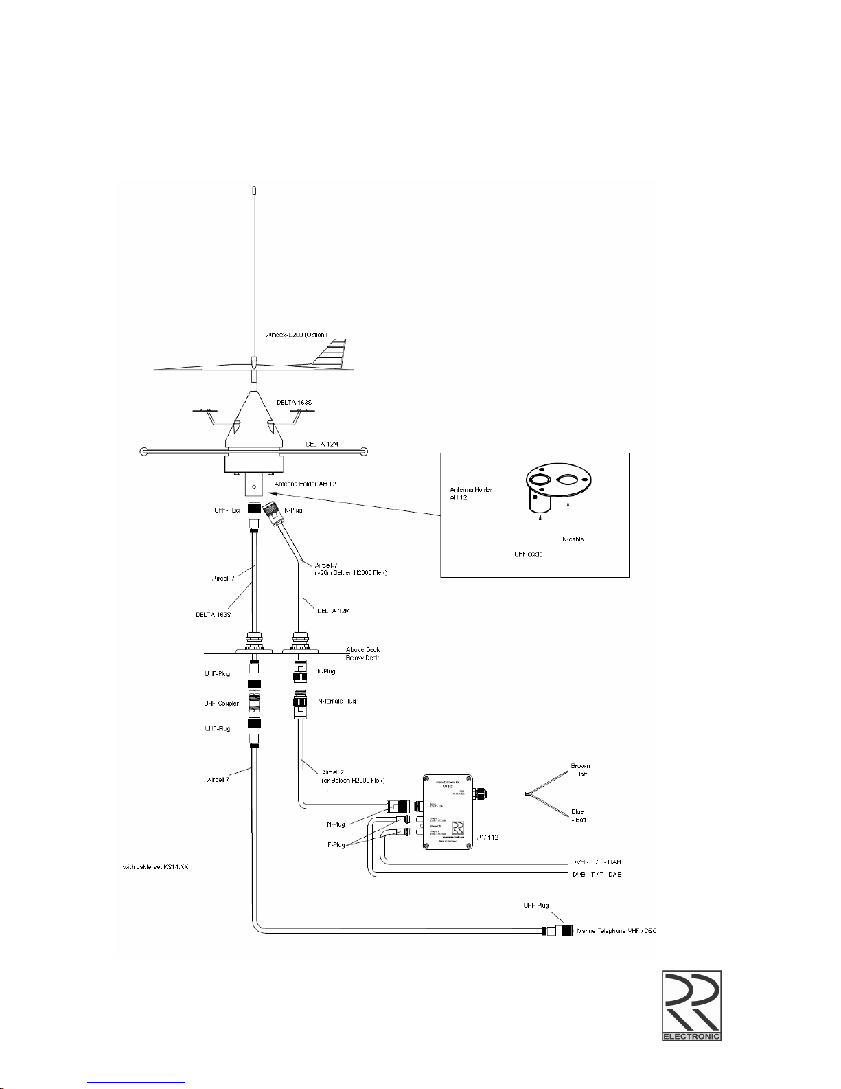
Antenna System ANTIGUA
Installation Diagram
Page 7

Specification subject to change without notice
 Loading...