

Page 1
Alpha
3V
Antenne für
UKW Seefunk,
DVB-T(2), FM, DAB+
Einbauanleitung
Antenna for
VHF Marine Radio,
DVB-T(2), FM, DAB+
Mounting Instructions
Page 2

Installation der Antennenanlage Alpha 3V
Die Antennenanlage Alpha 3V besteht aus der Antenne Alpha 3V und dem Antennenverteiler
DB2C.
Standort der Antenne
Die Antenne sollte möglichst freistehend aufgebaut werden. Bei der Auswahl des Standorts
ist zu beachten, dass die Antennenkabel eine Länge von 20 m nicht überschreiten sollten,
um eine einwandfreie Funktion zu gewährleisten.
Antennenkabel und Steckverbinder
Für die Verbindung zwischen der Antenne Alpha 3V und dem Antennenverteiler DB2C bzw.
dem VHF/AIS werden zwei dämpfungsarme Kabel mit 50 Ohm Wellenwiderstand und 5 mm
Außendurchmesser verwendet, z.B. H-155. Die maximale Kabellänge sollte 20m nicht
überschreiten, um eine einwandfreie Funktion zu gewährleisten. Als Steckverbinder werden
SMA und RP-SMA verwendet.
Wichtig: Sämtliche Metallteile der Antenne einschließlich Steckverbinder dürfen keine
elektrische Verbindung zu anderen Metallteilen des Schiffes haben, da der Außenleiter
des Kabels mit dem Minuspol des Bordnetzes verbunden ist. Bei Verwendung des
optionalen Antennenhalters AH3V ist gewähreistet, dass die Steckverbinder an der
Antenne keinen Kontakt zum Halter haben.
Zusammenbau der Antenne
An dem Antennenkabel für TV/Radio wird antennenseitig ein SMA-Stecker montiert; an dem
Antennenkabel für VHF/AIS wird ein RP-SMA Stecker montiert. Die Antennenkabel werden
an die Antenne angeschlossen, bevor diese mit dem Halter verschraubt wird. Wichtig: Die
Antennenstecker SMA und RP-SMA dürfen nicht verwechselt werden.
Für die Befestigung der Antenne auf dem Antennenhalter werden 4 Schrauben M5
verwendet. Die Schraubenlänge ist so zu wählen, dass das Gewinde max. 6 mm in das
Antennengehäuse geschraubt wird. Die mit dem optionalen Antennenhalter AH3V gelieferten
Schrauben sind passend bemessen.
Anschluss des Antennenverteilers DB2C
Wichtig: Die Stromversorgung darf erst nach Abschluss sämtlicher
Installationsarbeiten eingeschaltet werden.
Der Antennenverteiler DB2C wird unter Deck montiert. Das Antennenkabel für TV/Radio
verwendet auf beiden Seiten einen SMA-Stecker. Es wird mit dem Anschluss „Input Alpha 1C
Alpha 2T Alpha 3V“ des Verteilers DB2C verbunden. Die Ausgänge „Output 1“ und „Output 2“
des Veteilers werden mit einem DVB-T Empfänger oder einem FM- oder T-DAB-Radio
verbunden. Dazu werden 75 Ohm Kabel verwendet mit einem F-Stecker am Anschluss des
Verteilers DB2C. Wenn nur ein Gerät an den DB2C angeschlossen wird, wird der
mitgelieferte 75 Ohm Abschlusswiderstand auf den freien Ausgang geschraubt. Das
mitgelieferte Stromversorgungskabel wird mit dem 12V / 24V Bordnetz verbunden. Die rote
Ader wird mit dem Pluspol, die schwarze Ader mit dem Minuspol verbunden.
Direkter Anschluss der Antenne Alpha 3V an einen TV-Empfänger
Die Antenne Alpha 3V kann ohne DB2C direkt an einen TV-Empfänger angeschlossen
werden, wenn dieser eine Speisung der Antenne mit 5V zur Verfügung stellen kann. In
diesem Fall kann nur ein einzelner TV-Empfänger verwendet werden. Am Antennenkabel
wird ein zum TV-Empfänger passender Stecker angeschlossen, meist ein IEC-Stecker.
Page 3

Anschluss VHF / AIS
Das Antennenkabel mit RP-SMA-Stecker an der Antennenseite dient zum Anschluss eines
UKW Seefunkgerätes und / oder eines AIS Gerätes, ggf. über einen AIS-Splitter. Dieses
Kabel wird direkt am Gerät mit dem zu diesem Gerät passenden Steckverbinder
angeschlossen.
Wichtige Hinweise:
• Der Antennenteil für VHF/AIS funktioniert auch dann, wenn die
Stromversorgung des DB2C ausgeschaltet ist.
• Beim Senden mit VHF/AIS kann der TV- und Radio-Empfang gestört sein.
Für eine einwandfreie Funktion der Antennenanlage ist eine fachmännische Installation
sämtlicher Verbindungen, insbesondere aller Anschlussstecker unbedingt erforderlich!
Schäden durch Nichtbeachtung dieser Hinweise sind von der Garantie ausgeschlossen.
Im Zweifelsfalle einen Fachmann zu Rate ziehen!
Fehlersuchschema für Antennenanlage Alpha 3V
a) TV- / Radio-Empfang ohne Funktion
1. Prüfen dass die LED „Power ON“ leuchtet, andernfalls prüfen, dass die
Stromversorgung vorhanden ist und die Sicherung (M 0.125A; 5x20mm) heil ist.
2. Überprüfen der Steckverbinder und Verbindungen zu TV und Radio.
3. Überprüfen der Stromaufnahme des DB2C:
– mit angeschlossener Antenne 50mA bis 60 mA
– ohne angeschlossene Antenne 10 mA bis 16 mA
4. Überprüfen des SMA-Antennenkabels und der Steckverbindungen. Beim
Prüfen des Gleichstromwiderstandes mit einem Ohmmeter wird bei
angeschlossener Antenne ein Widerstand von ca. 3,5 kOhm gemessen.
5. Überprüfen der Ausgangsspannung vom DB2C zur Antenne: 5 V
6. Ist die Antenne Alpha 3V direkt an den TV-Empfänger angeschlossen,
prüfen, dass die Antennenspannung in den TV-Einstellungen eingeschaltet
ist.
b) VHF/AIS ohne Funktion
1. Überprüfen des RP-SMA-Kabels und der Steckverbindungen. Zwischen Innenund Außenleiter des Koaxkabels beträgt der Gleichstromwiderstand ca. 5 kOhm
bei angeschlossener Antenne.
Reparaturen an der Antenne oder am Antennenverteiler nur vom autorisierten Fachmann
durchführen lassen!
Page 4

Installation of Antenna System Alpha 3V
The antenna system Alpha 3V consists of the antenna Alpha 3V and the distribution box
DB2C.
Antenna position
The antenna should be mounted as free as possible. When selecting the antenna position,
take into consideration the maximum cable length of 20 m to provide perfect operation.
Antenna cable and connectors
Two low loss 50 Ohm cables of 5 mm diameter like e.g. H-155 are used between the
antenna Alpha 3V and the distribution box DB2C. The maximum cable length should not
exceed 20m to provide perfect operation.
Important: All metal parts of the antenna including connectors must not have
electrical contact to other metal parts of the ship because the shield of the cable is
connected to the negative pole of the power supply. With the optional antenna holder
AH3V the isolation of the connectors from the antenna holder is maintained.
Assembling the antenna
Mount a SMA connector for the TV cable at the antenna side. Mount a RP-SMA connector for
the VHF/AIS cable at the antenna side. Connect the cables to the antenna before fixing the
antenna to the antenna holder. Attention: Make sure that the connectors SMA and RP-
SMA are not mixed up.
Use four M5 screws to mount the antenna to the antenna holder. Make sure that the thread
of the screws can only reach at most 6 mm into the antenna case. The screws coming with
the optional antenna holder AH3V have the correct size.
Installation of the distribution box DB2C
Important: Do not switch on the power supply before the installation is completed.
Install the distribution box DB2C below deck. Mount a second SMA connector to the cable for
TV / Radio at the DB2C side of the cable. Connect the cable to the „Input Alpha 1C Alpha 2T
Alpha 3V“ of the DB2C. Connect the DVB-T receiver or FM / T-DAB radio to „Output 1“ and
„Output 2“ of the DB2C using 75 Ohm cables with F connectors at the DB2C output. If only
one of the outputs is used, screw the supplied 75 Ohm termination resistor to the unused
output. Connect the supplied red / black power cable to the 12V / 24V ship‘s supply system.
Connect the red wire to the positive pole and the black wire to the negative pole.
Direct connection of antenna Alpha 3V to a TV receiver
The antenna Alpha 3V can be connected directly to a TV receiver, if the TV receiver can
output a supply voltage of 5 V to the antenna. In this case only a single TV receiver can be
connected to the antenna. Mount the appropriate connector for the TV receiver to the
antenna cable, usually a IEC plug.
Connecting of VHF / AIS
Connect the cable with RP-SMA connector at the antenna to your VHF and / or AIS device
using a AIS splitter if necessary.
Page 5

Important:
• The VHF / AIS part of the antenna is operational even if the power to the DB2C
is switched off.
• The reception of Radio / TV may be impaired while transmitting on VHF / AIS.
To guarantee a perfect working antenna it is mandatory to do the installation in a workmanlike manner.
Any faults caused from neglecting these instructions are excluded from the manufacturers
warranty.
In case of doubt consult a specialist.
Trouble shooting of antenna system Alpha 3V
a) No TV / Radio reception
1. Check that the LED “Power ON” is iluminated. Otherwise check that the power supply
to the DB2C is available and check the fuse inside the DB2C (0.125A medium blow;
5x20 mm).
2. Check the cables and connectors to TV and FM radio.
3. Check the current consumption of the DB2C:
– With antenna connected 50 mA to 60 mA.
– Without antenna connected 10 mA to 16 MA.
4. Check the antenna cable especially the connectors. Checking the
resistance with an ohmmeter will indicate ca. 3.5 kOhm with the antenna
connected.
5. Check the output voltage from the DB2C to the antenna: 5 V
6. If the antenna is connected directly to the TV receiver, check that the
supply voltage from the receiver is enabled in the TV setup.
b) No VHF / AIS operation
1. Check the RP-SMA cable and connectors. Checking the resistance with
an ohmmeter should indicate ca. 5 kOhm with the antenna connected.
The antenna and distribution box may be repaired by authorized specialists only!
Page 6
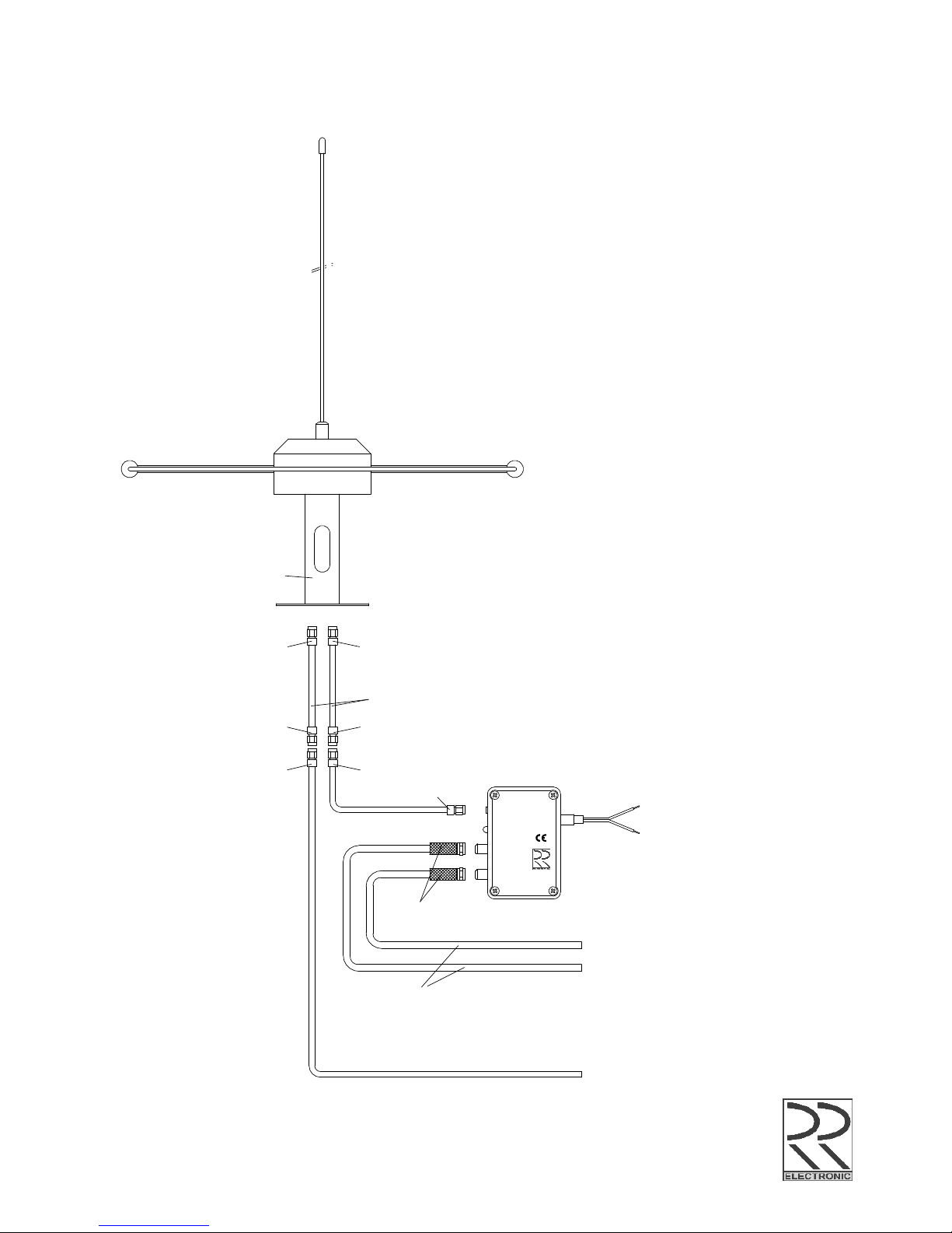
75 Ohm cable
Specifications subject to change without notice
Antenna system Alpha 3V
Installation diagram
(with DB2C)
Option Antenna holder AH3V
SMA Plug
RP-SMA Plug
SMA female PlugSMA Plug
SMA Plug
SMA female Plug
SMA Plug
F Plug
Power Supply
12-30V D.C.
Alpha 3V
DVB-T(2) / FM / T-DAB
DVB-T(2) / FM / T-DAB
DB 2C
20171116
H-155 max. 20m
VHF / AIS-Splitter
Red
+Batt.
-Batt.
Black
Distribution Box
DB 2C
Made in Germany
www.rr-electronic.com
Input
Alpha 1C
Alpha 2T
Alpha 3V
Output 1
DVB-T / DVB-T2
T-DAB / FM
Output 2
DVB-T / DVB-T2
T-DAB / FM
Power ON
Input
12 / 24 V DC
Page 7
Specifications subject to change without notice
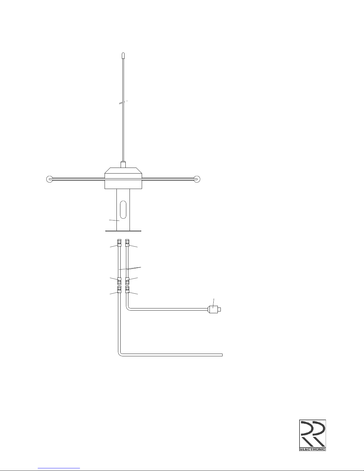
Antenna Alpha 3V
Installation diagram
(without DB2C)
Option Antenna holder AH3V
SMA Plug
RP-SMA Plug
SMA female PlugSMA Plug
SMA Plug
SMA female Plug
Alpha 3V
20171116
H-155 max. 20m
VHF / AIS-Splitter
IEC Plug
TV (with antenna supply)
 Loading...