

S
S
e
e
r
r
i
i
e
e
s
s
M
Mo
MM
od
oo
Ope
Operrrraaaattttoooorrrr aaaannnndddd PPPPaaaarrrrttttssss Man
OpeOpe
de
dd
el
ee
l
ll
Manuuuuaaaallll
ManMan
2222000000007777 V
Veeeerrrrssssiiiioooonnnn 1111....0000
VV
R.P.S. Corporation Phone: 1-800-634-4060
P.O. Box 368 Fax: 1-866-901-3335
Racine, Wisconsin 53401
HOW TO USE THIS MANUAL
This manual contains the following sections:
The SAFETY section contains important information
regarding hazard or unsafe practices of the machine.
Levels of hazards are identified that could result in product
or personal injury, or severe injury resulting in death.
- HOW TO USE THIS MANUAL
- SAFETY
- OPERATIONS
- MAINTENANCE
- PARTS LIST
The HOW TO USE THIS MANUAL section will tell
you how to find important information for
ordering correct repair parts.
Parts may be ordered from authorized dealers.
When placing an order for parts,
the machine model and machine serial number
are important. Refer to the MACHINE
INFORMATION page which is filled out during the
installation of your machine. The MACHINE
INFORMATION is located on page one of this
manual.
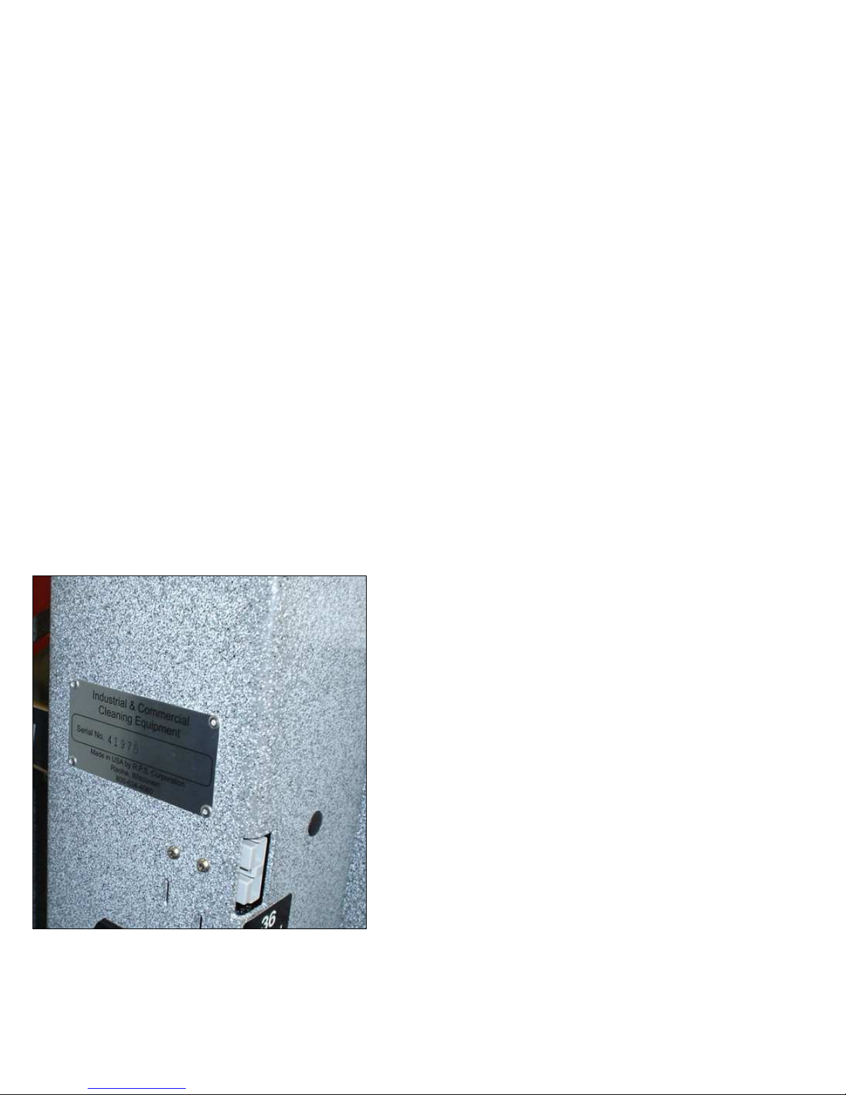
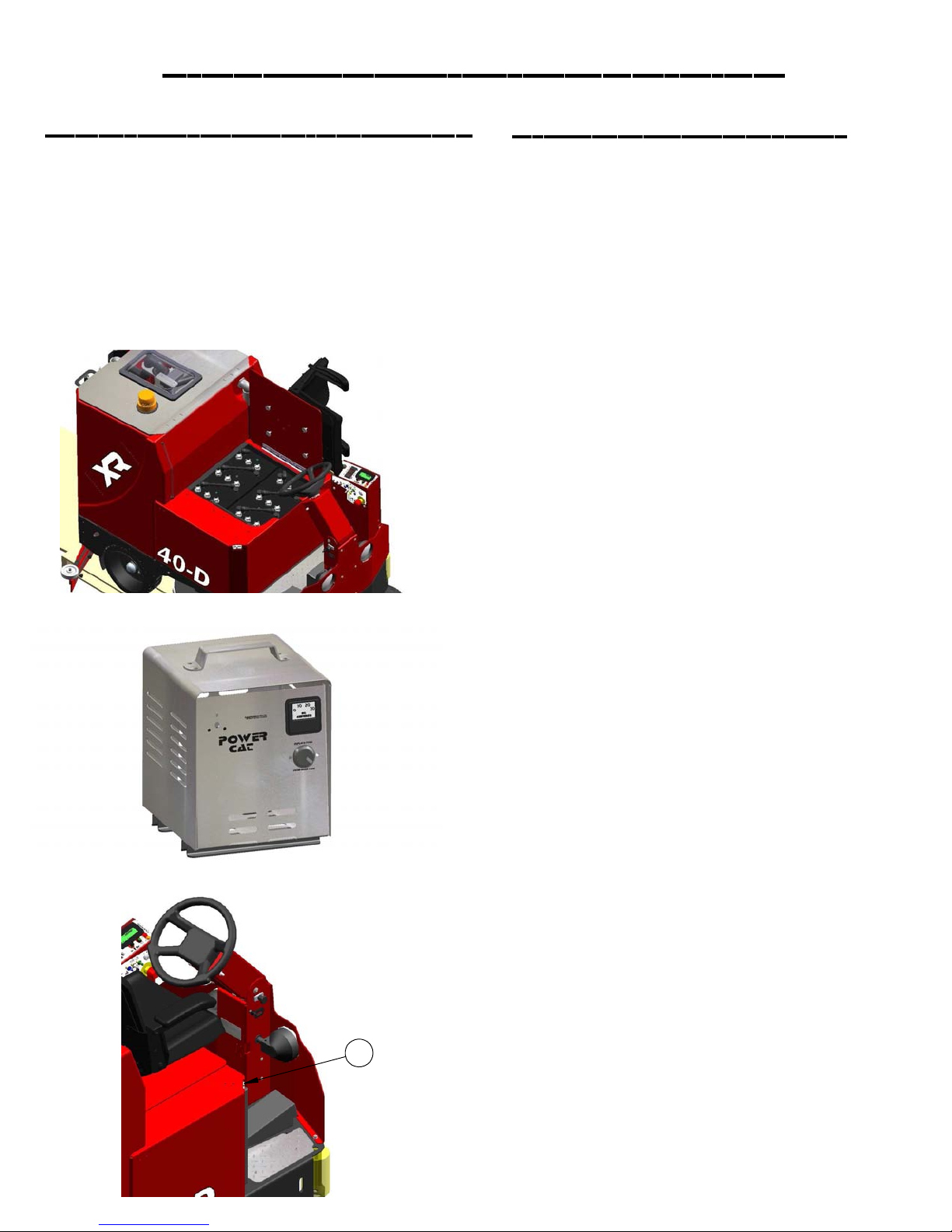
The serial number of your machine is located on
the lower steering pedestal of the steering
column of the machine. (See Picture Below)
The OPERATIONS section is to familiarize the operator with the
operation and function of the machine.
The MAINTENANCE section contains preventative
maintenance to keep the machine and its components in
good working condition. They are listed in this general order:
- Batteries
- Scrub Brushes
- Adjusting Squeegee
- Service Schedule
- Machine Trouble shooting
The PARTS LIST section contains assembled parts illustrations and
corresponding parts list. The parts lists include a number of
columns of information:
- ITEM - column refers to the reference number on the
parts illustration.
- PART NO. - column lists the part number for the part.
- QTY - column lists the quantity of the part used in that
area of the machine.
- DESCRIPTION - column is a brief description of the part.
- COMMENTS - column for information not noted by the
other columns.
NOTE: If a service or option kit is installed on your machine, be
sure to keep the KIT INSTRUCTIONS which came with the
kit. It contains replacement part numbers needed for
ordering future parts.

Table of Contents
Machine Information
Machine delivery form
Machine specifications
Common wear parts/scrub brushes
Safety messages
!!Safety precautions!!
Machine controls and features
Lcd screen menu displays
Machine setup
Attaching squeegee
Adjusting squeegee
Leveling scrub deck
Attaching brushes
Adjusting shrouds
Adjusting cylindrical side wipers
Solution system
Vacuum system
Machine operation
Draining recovery & solution tanks
Rec. Float shut off
Drain saver
Standard battery charging
Optional battery charging
On-Board charger operator manual
Changing batteries
Side broom system
Overhead guard
HD Side doors
On-board Soap
Spray hose
Vac wand
Diffuser exhaust bar
Stainless steel recovery tank
Stainless steel solution tank
Industrial battery
Removable battery box
On-Board soap
Spray hose
Vac wand
Maintenance & storing machine
Preventative maintenance records
Troubleshooting central command ii
Troubleshooting
Machine parts
Page 1
Page 2
Page 3
Page 4
Page 5
Page 6
Page 7-8
Page 9
Page 10
Page 11
Page 12
Page 13
Page 14
Page 15
Page 16
Page 17
Page 18
Page 19-21
Page 22
Page 23
Page 23
Page 24
Page 25
Page 26-28
Page 29
Page 30
Page 31
Page 31
Page 31
Page 31
Page 32
Page 32
Page 32
Page 32
Page 32
Page 32
Page 33
Page 33
Page 33
Page 34-35
Page 36-37
Page 38-39
Page 40-41
Page 42-93
Machine parts illustration
Front wheel drive
Side brooms (optional)
Front wheel side brooms and rollers
Disk deck
Shrouds
Cylindrical wipers
Cylindrical decks
Cylindrical doors
Attaching decks
Squeegee trail arm
53" Squeegee
60" Squeegee
Squeegee trail arm and rear axle
Dual vac motors
Vac motors and solution hoses
Tank Lid
Tank baffle
Solution/Recovery tank
Attaching tank
Standard batteries and seat
Optional battery and seat
Central command
Steering tower assembly
Central command and steering tower
Doors (optional)
Over head guard (optional)
Water jet kit (optional)
Vac wand kit (optional)
Page 42-43
Page 44-45
Page 46-47
Page 48-49
Page 50
Page 51
Page 52-53
Page 54-55
Page 56-57
Page 58-59
Page 60-61
Page 62-63
Page 64-65
Page 66-67
Page 68-69
Page 70-71
Page 72-73
Page 74-75
Page 76-77
Page 78-79
Page 80-81
Page 82-83
Page 84-85
Page 86-87
Page 88-89
Page 90-91
Page 92
Page 93

Machine Information
Model number_____________________________________________________________
Serial number:______________________________________________________________
Installation date:___________________________________________________________
Installing dealer:____________________________________________________________
Dealer contact: ___________________________________________________________
Address:___________________________________________________________________
City, state, zip: _____________________________________________________________
Phone number:_____________________________________________________________
This operator and parts manual should be considered a permanent part of the unit and should
remain with the unit at all times. This operator and parts manual covers all the XR series scrubbers.
You may find descriptions and features that are not on your particular model. The information
and specifications included in this publication were in effect at the time of printing.
R.P.S. Corporation reserves the right to make changes without notice incurring any obligation.
To register for warranty, fax your warranty registration form today! Fax # (886)-632-6961
PAGE 1

R.P.S. CORPORATION
COMPLETE AND FAX FOR
M to 866
-
632
-
6961
Customer Information
P.O. BOX 368
RACINE, WI 53401
PHONE: 800-634-4060
MMAACCHHIINNEE DDEELLIIVVEERRYY FFOORRMM
Dealer: __________________________ Installed By: ______________________
Location: (City, State)_______________ Install Date: ______________________
Name:________________________ Contact: _________________________
Address:_________________________ City/State:__________________Zip______
Phone Number :___________________ Fax Number: _____________________
Model Number:___________ Serial Number:______________ Hour Meter:____________
Squeegee Size:__________ Squeegee Material: Gum Linatex Neoprene (circle one)
Buyer’s representative has received instruction in proper operation of the following controls and features:
Filling Solution Tank, Solution Tank Sight Tube, Solution Drain Valve
Adjusting Controls and “Uni-Touch” operation, Double Scrubbing, Squeegee Delay & Vac Timer
Recovery Tank Draining and Cleaning, Vac Screen Removal and Cleaning
Shroud and Pad Removal
Shroud Adjustment
Solution Valve and Filter Operation (removal and cleaning)
Drain Saver Feature
Charging Operation
Seat and Steering Wheel Adjustment
LCD Screen Display Operation, 3 Hour Meters (keyswitch, brush, traction drive)
Tank Tilt Back Feature
Parking Brake Override
Checking Battery Electrolyte Level
Squeegee Hose Removal and Checking For Clogs
Battery Guide Poster Hung Up & Reviewed
Maintenance Guide Poster Hung Up & Reviewed
In addition to the items listed above the buyers representative has received the operator’s
manual and been advised to read the manual before operating the machine.
Installed By (print)______________________Signature________________
Buyer’s Representative (print)_____________________Signature_______________
BUYER AGREES TO PAY FOR ANY REPAIRS, ADJUSTMENTS, OR SECONDARY TRAINING THAT MANUFACTURER
DETERMINES IS EXCLUDED FROM THE WARRANTY
PAGE 2

Model
BODY CONSTRUCTION/DIMENSIONS
Tank Material:
Frame Construction:
Rear Wheels (diameter x width):
Drive Wheel (diameter x width):
Size (L x W x H):
Weight:
Weight (w/batteries):
BRUSH/PAD SYSTEM
Brush Down Pressure:
Brush Pressure Settings:
DISK
Brush/Pad Size:
Brush Speed:
Motor Power:
CYLINDRICAL
Brush SIze:
Brush Speed:
Motor Power:
XR
Poly (3/8” thick)
7-gauge (3/16” steel)
14” x 5”
12” x 4”
69” x 36” x 59”
1,230 pounds
1,950 pounds
0 - 350 pounds
(5) w/ auto adjust
370-34D: (2) 17”
370-40D: (2) 20”
270-rpm
(2) 1.5 hp
370-34C: (2) 32” x 7”
370-40C: (2) 38” x 7”
370-46C: (2) 44" X 7"
750-rpm
(2) 1.5 hp
BATTERY SYSTEM
Battery AH Rating (standard):
Battery AH Rating (optional):
Battery AH Rating (Industrial Steel-Clad Battery):
Battery Run Time:
Charger (110-v / 60 Hz, auto):
SOLUTION SYSTEM
Solution Tank Capacity:
Solution Flow Rate:
Solution Filter:
RECOVERY SYSTEM
Rec. Tank Cap.:
Vacuum Power:
Vacuum (Lift/Airflow):
Drain Hose (ID):
Demisting Chamber:
DRIVE SYSTEM
Power:
Type:
Speed Control:
PRODUCTIVITY
Cleaning Width:
Cleaning Rate/Hour:
(Qty 6) 325 AH
(Qty 6) 395 AH
(Qty 1) 440 AH / 1,280 pounds
Up to 6 hours
36-v / 36-amp
68 - gallons
0 - 1.5 gpm
Inline Stainless
68 - gallons
1.6 hp
68” / 140 cfm
2.0”
3-gallons
3.0 hp, sealed
All Gear
5.0 mph (FWD) / 3.0 mph (REV)
370-34: 34”
370-40: 40”
370-46: 46"
Up to 46,000 sq.ft/hr
WARRANTY
PARTS:
LABOR:
3 YEARS
1 YEAR
PAGE 3

Common Wear Parts
Item
Brush type
Brushes
Super-grit
Tough-grit
Midi-grit
Light-grit
Poly (.028)
Nylon (.022)
*Pad driver
Pads
Super black
Black
Brown
Green
Blue
Red
White
Brush Type
Super-grit
Tough-Grit
Midi-Grit
Light-Grit
Poly (.028)
Nylon (.022)
Tampico
*Pad Driver
Pads
Super Black
Black
Brown
Green
Blue
Red
White
Model
XR-34D
DISK (2)
17-421SS
17-421S
17-421C
17-421PS
17-421P
17-421N
17-421D
17-422BB
17-422B
17-422BR
17-422G
17-422BL
17-422R
17-422W
Disk
# # 421SS
# # 421S
# # 421C
N/A
# # 421P
# # 421N
N/A
# # 421D
Disk
# # 422BB
# # 422B
# # 422BR
# # 422G
# # 422BL
# # 422R
# # 422W
Model
XR-34C
Cylindrical (2)
NA
327-821S
327-821C
327-821PS
NA
327-821N
NA
NA
NA
NA
NA
NA
NA
NA
Cylindrical
NA
# # 521S
# # 521C
# # 521PS
NA
# # 521N
# # 521T
NA
Cylindrical
NA
NA
NA
NA
NA
NA
NA
MODEL
XR-40D
DISK (2)
20-421SS
20-421S
20-421C
20-421PS
20-421P
20-421N
20-421D
20-422BB
20-422B
20-422BR
20-422G
20-422BL
20-422R
20-422W
Level
Very High
High
High
Moderate
Moderate
Light
Light
Not Applicable
Level
Very High
High
High
Medium
Moderate
Moderate
Light
Model
XR-40C
Cylindrical (2)
NA
387-821S
387-821C
387-821PS
NA
387-821N
NA
NA
NA
NA
NA
NA
NA
NA
(10 The Highest)
10
9
8
6
5
2
1
(10 The Highest)
10
8
7
6
4
3
1
Model
XR-46C
Cylindrical (2)
NA
447-821S
447-821C
447-821PS
NA
447-821N
NA
NA
NA
NA
NA
NA
NA
NA
Color
Red/Orange
Black
Blue/Grey
Grey
Black
White
Tan
NA
Color
Black
Black
Brown
Green
Blue
Red
White
*Extra pad driver retaining clip: 40-433
Brush repair kit: 40-423 replacement locating clip for all disk brushes
Squeegee kits Size Gum Rubber Linatex
XR-34D and XR-34C 53" 370-770G 370-770L
XR-40D and XR-40C 53" 370-770G 370-770L
XR-46C 60" 380-770G 380-770L
Kit includes: (1) rear blade, (1) front blade.
Note: It is stamped into the top of the squeegee blank.
Model XR: Has a 53" squeegee unless other size is specially ordered at time of purchase.
Note: The smaller squeegees are designed for narrow aisles and may not have the same water
control around tight turns as the larger squeegees.
Soap
Heavy duty degreaser
Citrus
Freezer
Tire mark remover
For more soap information call PowerCat 414-745-9337 www.powercatsolutions.com
PAGE 4

Safety Message
Your safety, and the safety of others, is very important, and operating this unit safely is an
important responsibility.
To help you make informed decisions about safety, we have provided operating procedures
and other safety information in the manual. This information informs you of potential hazards
that could hurt you or others.
It is not practical or possible to warn you of all the hazards associated with operating this
unit. You must use your own good judgment.
This is intended for commercial use. It is designed to be used on hard floors in an indoor
environment, with the recommended pads or brushes.
1. Do not operate unit:
Unless trained and authorized.
Unless operator manual is read and understood.
If unit is not in proper operating condition.
Outdoors or exposed to rain.
For picking up hazardous materials/dust.
On surfaces having a gradient exceeding 2% unless the optional
Parking brake is functioning on the machine.
2. When operating unit:
Remove loose objects from the floor that may be projected from the
revolving brushes.
Keep hands and feet away from revolving brushes.
Do not operate machine where flammable liquids are present.
Use extreme caution when maneuvering.
3. Before leaving:
Make sure machine is turned off.
Stop on level surfaces.
Disconnect batteries.
4. Before servicing:
Stop on level surface, and secure machine.
Disconnect batteries.
5. Before discarding machine:
The batteries must be removed and properly disposed of.
PAGE 5

!! Safety Precautions!!
Warning: Hazardous voltage. Shock, burns or
electrocution can result. Always disconnect the
batteries before servicing machine.
Warning: Batteries emit hydrogen gases, explosion or
fire can result. Keep sparks and open flames away.
Warning: Charge unit in a well ventilated area, and
keep battery compartment open when charging.
Explosion or fire could result.
Warning: Battery acid can cause burns. Wear
protective eye wear and gloves when servicing
batteries.
Warning: Do not store outdoors or pressure wash.
Prevent from getting electronic components wet.
Warning: The use of parts and solutions other than
recommended by the manufacturer may cause
damage or endanger people.
Warning: Dress safely. Do not wear rings or metal wrist
watches while working on this machine. They can
cause an electrical short, which can cause serious
burns. Do not work on this machine while wearing a
tie, scarf or other loose, dangling neckwear or
clothing. These loose items can tangle in the rotating
parts and cause serious injury or even death.
Warning: Do not use the machine as a step ladder or
chair.
Warning: Only operate this machine from the
operator's seat. It was not designed to carry
passengers.
Warning: Always use the charger provided by the
manufacturer to charge the machine. It is an
automatic charger, specifically designed to charge
at the appropriate rate. If you must use a different
charger, disconnect the batteries before charging.
This will prevent damage to the electronic speed
controller.
Warning: Understand the dynamic braking system
before you operate the machine on ramps. Machine
does not coast. Releasing the foot pedal will
automatically apply braking force, and stop the
machine.
Warning: Do not park the machine on ramps or
slopes. The machine has a parking brake, but it is
recommended that it is always parked on level
ground.
Warning: Do not operate the machine if any parts
have been removed or damaged.
Warning: Do not remove, paint over, or destroy
warning decals. If warning decals become
damaged, they must be replaced.
Warning: Do not operate machine in unsafe
condition. If the machine is in need of repair or is in
any way unsafe to operate, the matter should be
reported immediately to the shift supervisor. Do not
operate the machine until it is returned to proper
operating condition.
Warning: This machine must only be operated by
trained operator. As part of his or her training, they
must read this manual thoroughly. If extra copies are
needed, contact your local dealer.
Warning: Do not operate this machine on ramps or
uneven surfaces. When climbing a ramp, always drive
the machine in forward straight up or down the ramp.
Never drive across the incline. Do not back down or
turn on ramps!
Warning: Do not attempt to push or pull the machine
without first manually overiding the parking brake and
disconnecting both leads to the traction motor.
(See page 21 for pictures)
Warning: Always turn off the machine, before leaving
it unattended.
Warning: Do not operate over electrical floor outlets,
may result in serious injury.
PAGE 6

Machine Controls and Features
3
7
2
1
6
5
4
15
21
8
9
10
11
12
13
14
30
31
32
29
17
16
19
20
18
36
37
PAGE 7
35
22
23
24
33
34
25
38
39
50
40
41
42
26
27
43
28
4746
22
44
45
48
49

Controls and Functions
1. Steering wheel: Steers the machine.
2. Adjustable seat with arm rests: Your machine is equipped with an adjustable seat with arm rests.
3. Recovery tank lid: Latch must be secured for recovery tank to seal properly.
4. Polyurethane rollers: Helps prevent damage to machine and objects you may drive close to.
5. Adjustable disk deck side wipers: Controls water on turns by directing it to the squeegee.
6. On board charger (optional): Plugs into any three pronged 20 amp dedicated outlet to charge
machine
7. Horn button: Sounds the horn for warning oncoming traffic.
8. Headlight switch: Turns headlight on and off.
9. Adjustable steering: Four settings for operator comfort and ease of entry.
10. Hour meter: Keeps track of total hours of use on the machine.
11. Serial # plate: Have machines individual serial number stamped on it.
12. Foot pedal: Controls the acceleration and deceleration of the machine.
13. Cup holder: Holds beverage container.
14. Onboard soap: (optional) Automatically meters concentrated detergent to scrub deck.
15: Strobe light: (optional) Warns people that the machine is in operation.
16. Recovery drain hose: Allows for controlled draining of recovery tank dirty water.
17. Spray hose: (optional) Permits cleaning in remote areas.
18. Squeegee/vacuum hose: Vacuumizes squeegee. Note: keep free and clear of blockage.
19. Site tube/ sol. drain hose: Shows how much solution is in the tank and drains the solution tank.
20. Rear bumper: Offers squeegee system protection from damage.
21. Tank latch: Permits access to tank.
22. Tie down points: Location for tie down straps during transport.
23. Squeegee rollers: Help protect the squeegee.
24. Rear Tire: Solid Tire.
25. Adjustable cylindrical deck side Wipers: Controls water on turns by directing it to the squeegee.
26. Cylindrical Deck Access Door: Provides easy access to the decks belts & pulleys.
27. Charger Port: (Grey 175) Receives charger input. (Only use OEM charger provided)
28. Side Brooms: Extends the cleaning path up to walls.
29. Solution fill port: Holds approximately 68-gallons of clean water.
30. Recovery tank: Holds approximately 68-gallons of dirty "recovery" water.
31. Drain saver: Prevents debris from clogging drain.
32. Foam protection screen: Used to protect vacuum motor from debris.
33. High water recovery light (red): Indicates when the recovery tank is nearly full.
34. Low solution light (yellow): Indicates when the solution tank is nearly empty.
35. LCD screen: Lists functions and setting of the machine. (See page 9)
36. Squeegee switch: Raises and lowers the squeegee.
37. "Uni-touch" button: Activates brushes, squeegee, and solution flow simultaneously.
38. Menu control: Scrolls through different options on the LCD display.
39. Scrub deck down pressure switch: Controls the pressure put on the scrub deck.
40. Scrub deck switch: Raises and lowers the scrub deck.
41. Solution control: (-) to reduce & (+) to increase flow of solution.
42. Forward/reverse switch (red): Controls the direction of the traction motor.
43. Spray jet (blue): (optional) Activates spray pump for remote spray wand.
44. Vacuum switch (white): (optional) For use with remote vacuum wand.
45. Key switch: Turns the main power on and off.
46. Side broom (yellow): (optional) Lifts and lowers side brooms which turn on automatically.
47. Water to side brooms (grey): (optional) Provides cleaning chemical to extend cleaning path.
48. Recylcling switch (green): (optional) Turns on the recycling pump.
49. Emergency stop: (optional) Shuts machine down in a emergency
50. Managers lockout: (optional) Limits the operator's ability to make unauthorized adjustments.
PAGE 8

LCD Screen Menu Displays
SCREEN # 1 (Operator)
1
11
2
10
4
3
SCREEN W/ERROR CODE
1
SCREEN #3 (Maintenance)
5
6
7
1
8
11
***Use green menu selection button on control panel to change screens***
1. Battery level indicator - Indicates the energy level remaining in the batteries. (Shown on all menu displays)
2. Scrubdeck down pressure gauge - Sets the down pressure on the brushes.
3. Vacuum on - Indicates the vacuum is "on".
4. Scrub motors on - Indicates the brush motors are "running".
5. Key switch hour meter - Tells you the total hours the machine has been on.
6. Scrub brush hour meter - Tells you the total hours the brush motors have been used.
7. Transport hour meter - Tells you the total hours the drive system has been used.
8. Error warning symbol - Indicates when there has been a diagnostic code error.
9. Diagnostic code - When the machine has detected an error it will display the warning symbol
and a diagnostic code which tells you what's wrong.
10. Water on - Indicates the solution flow is "on"
2
9
11. Solution level - Indicates the gallons per minute (G.P.M) 0 - 1.0 .
(For common error codes and descriptions see pages .)
PAGE 9

Machine Setup
Uncrating Machine and
Connecting Batteries
1. Carefully check the crate for any signs of
damage. Batteries are in the unit.
2. To uncrate the machine, remove banding
from around the crate. Take off the top and
sides and dispose of properly.
3. Remove banding from machine. Remove
the chocks around the drive wheels.
4. Turn all switches to the off position and
remove key.
5. Tip back seat to expose the battery
compartment and check to see that the
battery cables are connected.
A standard machine is equipped with (6) 6-volt,
deep cycle, 325 ah batteries, which form a 36
volt system. Maximum battery dimensions are
7-1/8"W x 12-1/4"L x 13-1/4"H.
6. Verify that all of the battery cables are
connected to the batteries tightly. Locate any
loose ones and connect to the open terminal.
Tighten with 9/16" wrench. (DO NOT OVER
TIGHTEN!) Batteries are heavy but easily
damaged. Put covers in place. (See picture to
the left)
7. Turn on main power switch and check the
battery condition meter to ensure correct
installation.
8. Fold down ramp, and drive machine off of
the base.
Notify the carrier immediately if concealed
damage is discovered.
PAGE 10

Attaching Squeegee
1. Lower the squeegee mounting plate by
depressing the squeegee switch (A) to the
down position. (See picture below)
A
Removing Squeegee
1. With the squeegee in the down position, turn
key switch off & remove key.
2. Disconnect vacuum hose from squeegee and
loosen the (4) knobs.
3. Pull squeegee assembly rearward from the
lifting carrier.
4. Inspect or repair as necessary and reinstall.
Replacing or Rotate
Squeegee Blades
2. Loosen the four knobs (B) on the
squeegee and slide them into the slots in the
squeegee mounting plate. (See picture below)
3. Tighten the four knobs (B) and connect
vacuum hose (C) from the machine to the
squeegee.
(See picture below)
4. You may have to adjust the squeegee
pitch by turning the pitch adjustment knob (D).
(See picture below)
For safety: before leaving or servicing the
machine, stop on a level surface, turn off
machine, and remove key.
1. Remove the squeegee assembly from the
machine.
2. Loosen latch (E) and swing both retaining
straps away from squeegee to remove the
rear squeegee blade. (See picture at lower left)
3. To remove the front squeegee blade,
remove all the knobs (F) on the front of the
squeegee assembly, then remove the
retaining strap that secures the blade in place.
(See picture below)
4. Rotate the squeegee blades to new edge
position or replace as required.
5. Install blades on the locating pins of
squeegee assembly.
6. Reinstall squeegee retainer straps.
C
D
5. Note vac exhaust, dual vac out
*assists in drying (See picture above)
7. Retighten front knobs & rear latch.
B
E
F
PAGE 11
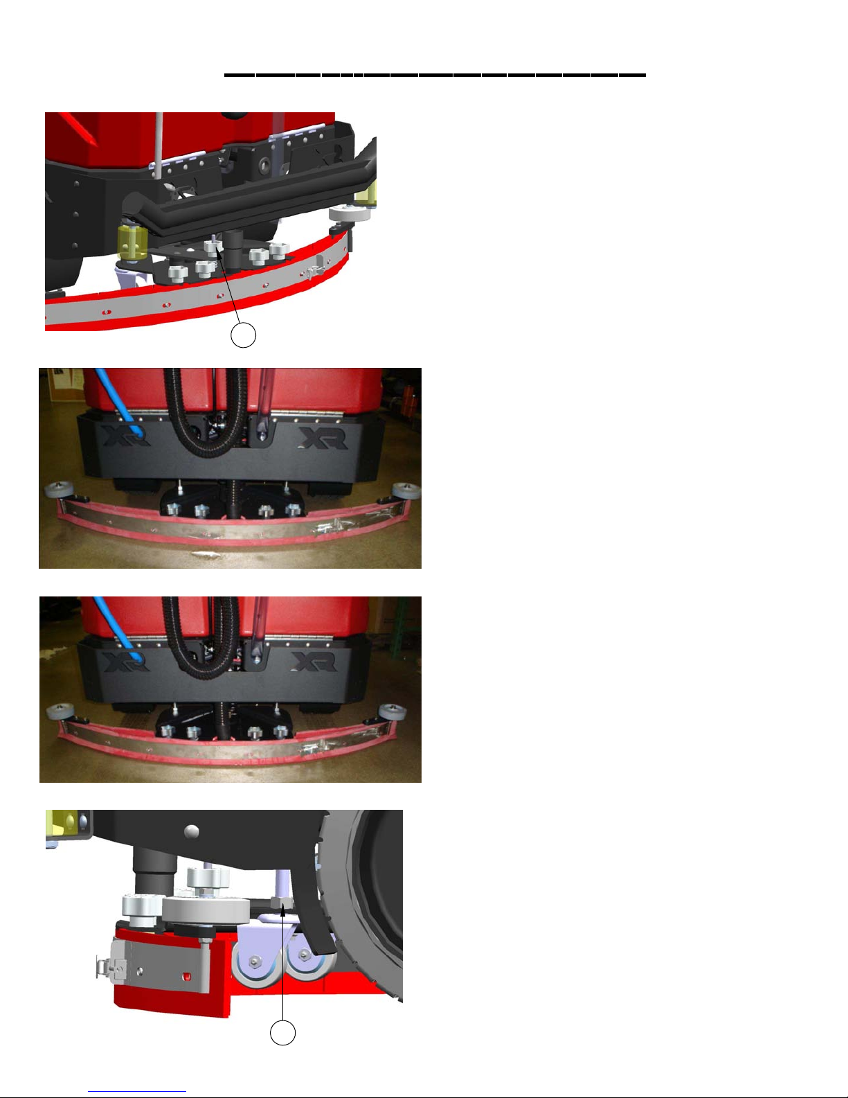
Adjusting Squeegee
1. Turning adjustment knob clock-wise
(Tightening) will raise tips & lower center.
(See picture to the left)
1
2. This squeegee is adjusted too far back and
will not pick up on the corners. Note tips of the
blades are off the floor.
(See picture to the left)
A
3. This squeegee is adjusted just right with good
deflection across the entire rear blade.
(See picture to the left)
4. To adjust the squeegee trail wheels, first
loosen locking nut (A). Then turn the wheel
assembly clock-wise until it bottoms out against
the mounting plate and back it off (3) full turns.
This is a starting point for adjustment. Raise or
lower as needed. Retighten locking nut.
PAGE 12

Measure from
deck to floor
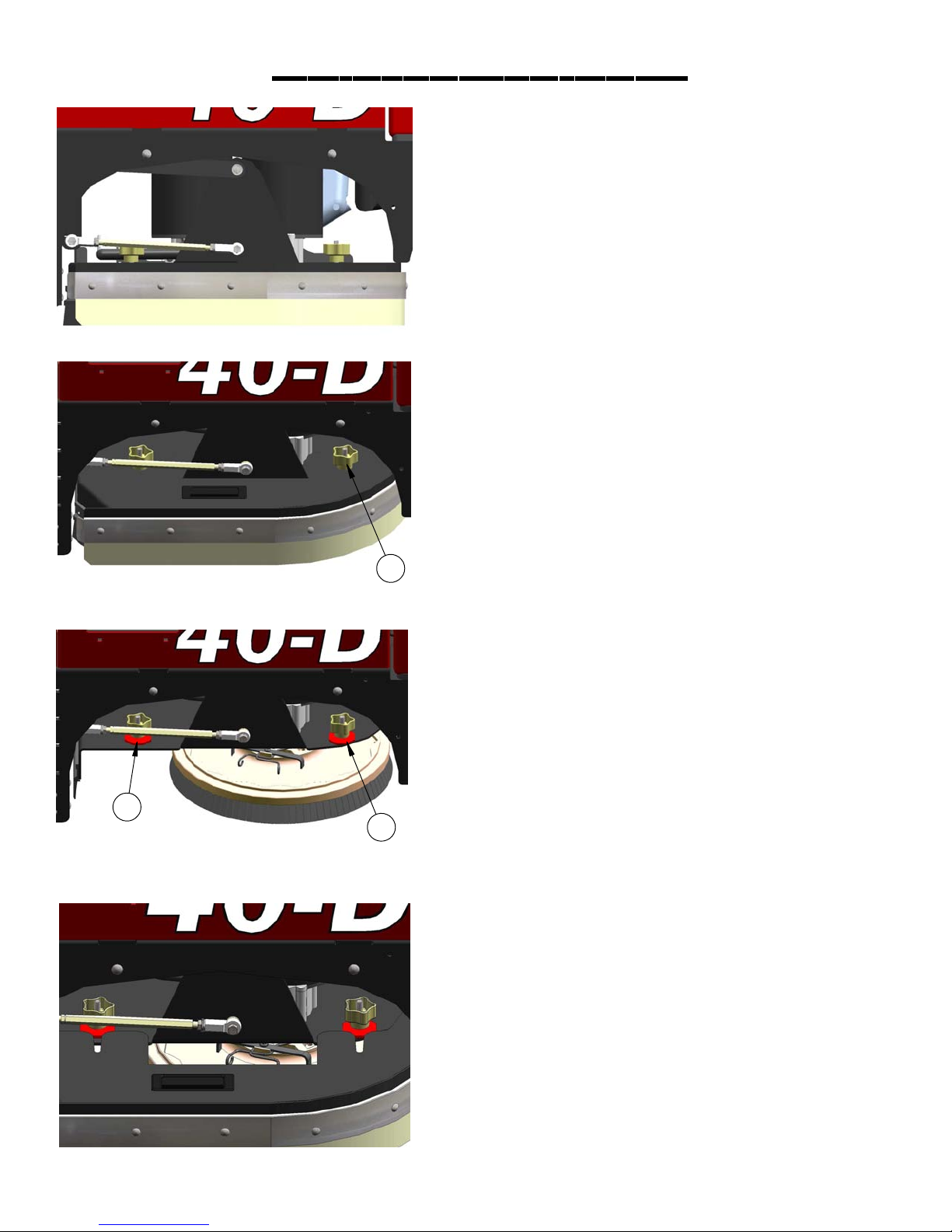
Leveling Scrubdecks
Leveling Disk Scrubdeck
1. Drive machine to a flat level surface and
turn machine off. (See picture to the left)
2. Deck should be raised off the floor.
3. With the shrouds off, measure from the ground
to a parallel surface on all four corners of the
Measure from
deck to floor
scrubdeck. (See picture to the left)
3. If the measurements are not the same the
deck is not level and needs to be adjusted.
4. Loosen the (2) locking nuts (4) and adjust
the hexagonal arm (5). (See picture to the left)
5. Extending the adjustable arms raises the
front and lowers the rear of the scrubdeck.
Measure & Retighten. (See picture to the left)
54
4
5
4
Leveling Cylindrical
Scrubdeck
1. Drive machine to a flat level surface and
turn machine off.
2. Raise the deck off the floor.
3. Measure from the ground to a parallel edge
on all four corners of the scrubdeck.
4. If the measurements are not the same the
deck is not level and needs to be adjusted.
5. Loosen the locking nut (4) and turn the
hexagonal arm (5) on each side of the
scrubdeck to level it. (See picture to the left)
Measure from
deck to floor
6. Extending the adjustable arm raises the
front and lowers the rear of the scrubdeck.
Measure & Retighten. (See picture to the left)
Measure from
deck to floor
PAGE 13
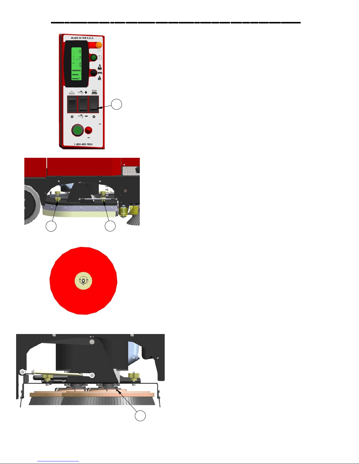
Attaching Disk Brushes/Pads
1. Turn "on" machine power.
2. Raise the scrub deck by depressing the
brush switch (A) to the ("0") position and turn
machine power "off". Disconnect batteries.
(See picture to the left)
A
3. Loosen knobs (B) and remove shrouds to access
scrub deck (See picture to the left)
B
B
4. Attach pads to pad drivers before connecting
pad drivers to motor hub. (See picture to the left)
5. Attach brushes or pads to motor hubs.
squeeze the scissor locking device (C) and lift
brush up on to the motor drive hub. Make
sure the scissors close and lock once the
brushes are on. (See picture to the left)
6. When brushes are attached put shrouds
back on machine and tighten knobs.
***FOR CORRECT PAD APPLICATION , CALL YOUR LOCAL DEALER***
C
PAGE 14
Adjusting Shrouds
1. The shroud must be adjusted correctly in order
to have proper water control during turns.
the front of the shroud should be slightly
higher than the rear. (See picture to the left)
2. To adjust shrouds loosen knobs (A) and
remove shroud. (See picture to the left)
A
3. Spin the RED shroud support (B) up or down to get
adjustments. (See picture to the left)
B
B
4. Once adjusted to the proper height put the shrouds
back on top of adjustment supports and tighten
knobs back down. (See picture to the left)
PAGE 15

Adjusting Cylindrical Side Wipers
1. The cylindrical deck comes euipped with side wipers
for increased water control when turning.
(See picture to the left)
C
2. To adjust the side wipers, first loosen the locking nut
(A), then turn the adjusting screw (B) in to raise or out to
lower the height of the side wiper blade. The spring (C)
provides tension during adjustment.
(See picture to the left)
B
A
4. A properly adjusted side wiper will have slight blade
deflection on the floor when turning.
(See picture to the left )
PAGE 16
DONT LAY
UNDER TANK!
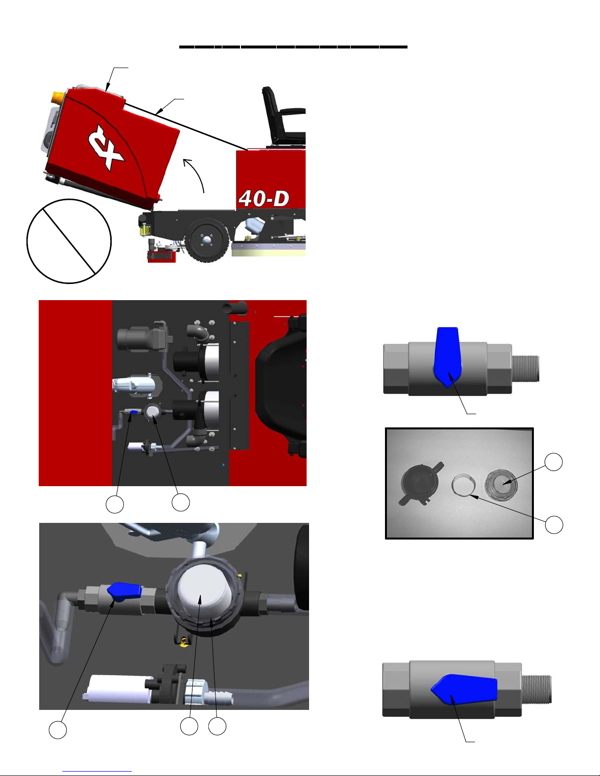
Solution System
BOTH TANKS EMPTY !
STRAP
1. To access the items listed below,
completely drain solution and recovery
tanks (See picture to the left)
I. Carefully tip the tank back until it is
supported by the strap.
II. Gate Valve
III. Stainless steel inline filter
IV. Solution Flow Valve
2. To clean filter (A) close gate valve (B).
(See pictures to the left & below)
Closed Position
C
B
A
D
3. Unscrew clear lid (C), remove
stainless steel screen (D), rinse screen.
(See pictures above & to the left)
4. Reinstall stainless filter screen & tighten
cap.
5. Open gate valve (E)
(See pictures to the left & below)
E
CD
Open Position
PAGE 17

A
Vac System
1. The "high recovery" light (A) (red) will
illuminate and the horn will sound when the
recovery tank is full. Stop immediately and drain
the recovery tank. (See picture to the left)
2. If the red light is ignored the vac motor will
overheat.
B
3. If the vac motor is pulling excessive current,
circuit breaker (B) (50 amps) may blow to
prevent damage. If this occurs contact your
service agent.
C
4. Vac switch (C) is set to engage at 45-50" of lift.
C
5. If foam or water gets past the recovery
tank "vac screen/ball system" (C) the
"unloader valve" (D) will drain it from the vac box.
(See picture to the left and picture below)
6. "Unloader valve" (D) is located on the bottom of
the vacuum box in front of the vac motor.
(See picture to the left)
D
PAGE 18

Operation
Pre-cleaning check list
Read and understand the safety section on
page 5 and 6 before operating machine.
1. Check battery condition gauge on
the Central Command II LCD screen.
Make sure batteries are fully charged
before using.
2. Check the condition of pads or brushes.
3. Check the condition of the squeegee blades.
4. Transport the machine to the filling
station. Raise the scrub head and
squeegee when transporting.
5. Turn machine off.
6. Open solution fill door on the top of
the tank and fill the tank up with
clean water or "approved" detergent. For help call
Powercat Solutions at 414-745-9337. Foam in the
recovery tank is usually an indication of excessive soap.
(See picture below.)
One pass scrubbing
Steps: (see picture below)
1. Turn machine on with the key switch.
2. Lower squeegee by pressing the switch.
3. Lower scrub head to the floor, use the
top half of the brush switch.
4. Adjust the solution +/- to the desired
setting. (start at half way).
5. Begin scrubbing by depressing the
foot pedal slowly and then to the speed
required. (Not shown)
6. Start scrubbing at the #1 or # 2 marks,
do not use the #4 or # 5 marks without
management's approval.
7. To operate machine in reverse,
simply switch the reverse switch to
the reverse position, back up alarm
may sound and your reverse speed
is set to roughly 70% of forward.
7. Add cleaning chemical. Use the proper
dilution ratio indicated on the bottle.
Note: Use only nonflammable commercial
cleaning chemicals.
Solution Fill Port
Solution Fill
"Sight Tube"
8. To stop the machine, let off of the
foot pedal and the machine will
stop automatically. (Not shown)
9. Depressing the "uni-touch" button activates
the solution, vacuum, and brushes
simultaneously.
1
6
2
3
4
9
7
PAGE 19

Operation
Double Scrubbing
Steps: (see picture below)
1. Turn machine on with the key switch.
2. Lower scrub head to the floor, use the
top half of the brush switch.
3. Adjust the solution to the desired
setting. (set half way)
4. Begin scrubbing by depressing the
foot pedal slowly and then to the speed
required. (Not shown)
5. Start scrubbing at the # 1 or # 2 marks,
do not use the # 4 or # 5 marks without
management's approval.
6. To operate machine in reverse,
simply switch the reverse switch to
the reverse position, back up alarm
may sound and your reverse speed
is set to roughly 70% of forward.
Vac Only Scrubbing
Steps: (see picture below)
1. Turn machine on with the key switch.
2. Lower squeegee by pressing the switch.
3. Begin vacuuming by depressing the
foot pedal slowly and then to the speed
required. (Not shown)
4. To operate machine in reverse,
simply switch the reverse switch to
the reverse position, back up alarm
may sound and your reverse speed
is set to roughly 70% of forward.
5. To stop the machine, let off of the
foot pedal, and the machine will
stop automatically. (Not shown)
7. To stop the machine, let off of the
foot pedal, and the machine will
stop automatically. (Not shown)
1
5
1
2
4
2
3
6
PAGE 20

Operating Hints
C
B
A
1. Observe the amount of solution the machine is
dispensing on the floor and adjust to the desired flow.
To increase the solution flow rate, push solution switch
(A) +, to decrease push solution switch (A) -.
(See picture to the left)
2. Keep an eye on the "red" recovery full light (B) to
make sure there is not foamy buildup in the recovery
tank. If excess foam begins to develop, pour a
recommended foam control solution into the
recovery tank.
(See picture to the left)
3. Always operate at lower speeds when scrubbing
around walls and objects. You should reduce the
speed, to maintain control when turning.
4. If squeegee starts to streak, raise and wipe the
blades with a clean cloth. If the problem continues,
check the blades for wear or damage, and rotate if
needed.
5. Change or turn over pads when dirty. Rotate the
scrub brushes every week.
Sight Tube
6. Stay clear of objects protruding from the floor,
such as sockets, grates, for they will damage the
pads and squeegee blades.
7. During brief stops you should turn everything off,
the brushes and solution will automatically stop when
the foot pedal is released.
8. Always keep an eye on your gauges. They let you
know the status of a particular system at a glance. If
your battery gauge is reading low, you must stop
immediately, and recharge. Running the batteries
dead, will result in damage to the batteries.
9. When you run out of solution, raise the brushes,
and continue to vacuum the remaining water until it
is consumed. The "yellow" low solution light (C) will
light up when the solution is low and the sight tube
on the back of the tank tells you how much solution
is left in the tank, (See picture to the left)
10. When you are ready to stop, pick up the brushes,
turn off the solution switch, pick up the squeegee,
and drive the machine back to the charging area.
PAGE 21

Drain Solution Tank
Drain Recovery Tank
To drain left over cleaning solution from the solution tank,
perform the following steps.
1. Pull the clear sight tube/drain hose (A) off barbed fitting.
(See picture below)
2. Rinse out tank and solution flow system with clean water.
A
Overide Parking Brake
Always empty recovery tank when refilling the solution
tank. To drain the recovery tank, perform the following
steps.
1. Remove drain hose "B" and unscrew cap. Open the
top "recovery access lid" and flush out with fresh water
to keep tank clean. (See picture below)
B
2. Remove cap and begin draining, squeeze "C"
to control flow. (See picture below)
The parking brake must be released "prior" to attempting to
"push/pull" the machine manually. Perform the following
steps in any order.
1. Disconnect both positive and negative leads (1 & 2) from
the traction motor. (See picture below)
1
2
2. Turn wingnut (3) clockwise to release the parking brake.
(See picture below)
C
* It is the customers responsibility to verify that discarded
water is in compliance with local, state, and federal
laws. DO NOT DRAIN INTO "STORM DRAINS" !
3. Open the top "recovery tank lid" and flush out with
fresh water to keep tank clean. Rinse the recovery tank
after every use. This will prevent heavy build up on the
bottom of the tank, foul odors and clogging of the drain
hose. Empty "Drain Saver".
3
4. Once tank is empty, put the cap back on and place
hose back on hook.
PAGE 22

Recovery Tank
Recovery Tank
Float Shut-Off
When water is no longer being vacuumed
from the floor and the vacuum fan is
operating, the ball float has engaged the red
high recovery light (1) will come on.
(See picture below)
The vacuum motor will not vacuum water with
recovery tank full. The recovery tank must be
drained
1
Drain Saver
The recovery tank drain saver will help prevent the drain
from becoming clogged with debris.
1. The drain saver screen should be emptied and cleaned
after you drain the tank.
2. To clean, pull hose (4) out of drain saver and remove
screen. Empty screen into trash, wipe material off screen
and then rinse.
4
1. The float shut-off (2) screen can be
cleaned in or out of the machine.
2. To clean the float shut-off while it is inside
the machine wipe material off screen
then rinse. Check that the ball is also
clean and moves freely.
3. To remove the float shut-off, remove the
white clamp (3) grasp the screen with one
hand and pull down to remove.
4. Screens, gaskets, and shutoff balls must be
in place.
3. When finished place screen back into the recovery tank
and re-insert hose into screen (5).
5
3
2
4. The screen saver must always be in place when the
machine is in use to prevent clogging of drain.
PAGE 23
Standard Battery Charging
Charger Specifications
Output voltage of 36 volts. (Standard)
Output current of 36 amps max. (Standard)
Input voltage of 110 volts/60 Hz. (standard)
Automatic shut off circuit.
Made for deep cycle batteries.
Danger: always charge batteries in a well ventilated area.
Batteries emit hydrogen gas. Explosion or fire can result.
Keep sparks and flame away. Shield eyes when servicing
batteries and avoid contact with battery acid.
Leave access panel open when charging!
Standard Charger
Caution: the following instructions are intended for the
36v charger supplied with the machine. Do not use
any non OEM charger with this machine.
1. Transport machine to a well ventilated area for
charging.
2. Turn the machine off.
3. Hinge opens the tank to expose the batteries.
(See picture to the left)
Caution: (always wear eye protection when batteries
are exposed)
4. Check the water level in each battery. Do not
charge the machine unless the water is slightly higher
than the plates. If needed, add enough distilled
water to 1/2” above the plates. Do not over fill.
Batteries can overflow during charging. Replace
caps before charging.
5. With the grey (175) charger plug disconnected
from the machine, plug the charger power cord into
a grounded 110 volt standard wall outlet.
6. Connect the grey charger plug into the battery
charging port (A) located on the seat pedestal.
7. The charger will automatically begin charging,
and automatically shut off when fully charged
(Check gauge)
8. After the charger has turned off, unplug the grey
charger plug from the machine and disconnect the
A
charger from the wall outlet.
9. Recheck the cell level after charging. If needed,
add distilled water up to the correct level. Be certain
to replace the caps securely and to wipe off the top
of the batteries.
PAGE 24

Optional Battery Charging
Charger Specifications
Output voltage of 36 volts. (optional)
Output current of 30 amps max.
Input voltage of 110 volts/60 Hz.
Automatic shut off circuit.
Made for deep cycle batteries, wet or sealed.
Danger: always charge batteries in a well ventilated area.
Batteries emit hydrogen gas. Explosion or fire can result.
Keep sparks and flame away. Shield eyes when servicing
batteries and avoid contact with battery acid.
Leave access panel open when charging!
On-Board Charger
Caution: the following instructions are intended for the 36v
"optional" on-board charger (A). (See left middle picture)
1. Transport machine to a well ventilated area for
charging.
2. Turn the machine off.
3. Hinge open the tank to expose the batteries. (See figure
50.) Caution: (always wear eye protection when batteries
are exposed)
4. Check the water level in each battery. Do not charge
the machine unless the water is slightly higher than the
plates. If needed, add enough distilled water to 1/2” above
the plates. Do not over fill. Batteries can overflow during
charging. Replace caps before charging.
5. Plug the extension cord into a grounded 110 volt/60 Hz
standard wall outlet & flip switch. (See picture to the left)
* NOTE: MUST HAVE 20 AMP SERVICE.
A
6. The charger will automatically begin charging, and
automatically shut off when fully charged
(Check gauge)
7. After the charger has turned off, unplug the extension
cord from the machine and disconnect from the wall
outlet. (See picture to the left)
8. Recheck the cell level after charging. If needed, add
distilled water up to the correct level. Be certain to replace
the caps securely and to wipe off the top of the batteries.
Description of LED
Red LED Battery level low.
Yellow Led Battery at 1/2 charge.
Green LED battery fully charged.
Close-up of charger LCD
PAGE 25

On-Board Charger Operator Manual
Charge Status LED's
LCD Display
Main Power
Switch
PAGE 26

On-Board Charger Operator Manual
PAGE 27
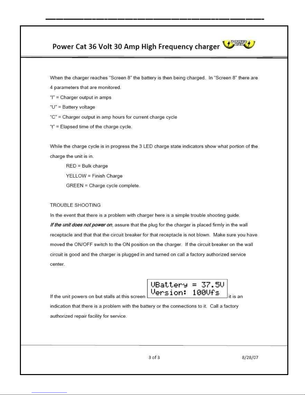
On-Board Charger Operator Manual
PAGE 28
Changing Batteries
Stop machine in a clean area next to the charger. Turn off machine.
For safety: Before leaving or servicing the machine; stop on level surface, turn off machine and remove key.
Use eye protection.
1. Tip back tank to expose batteries.
2. Disconnect main battery cables from machine.
3. Use the proper size wrench to disconnect main ground wire first and secure cable terminal away from batteries.
4. Disconnect main positive lead and secure cable and remove one at a time.
5. Loosen both terminals on each jumper cable and remove one at a time, and place away from machine.
6. Prepare a suitable site to place the batteries, store on a wood pallet, not on concrete.
7. Attach suitable battery lifting device and lift batteries from the machine
Warning!
Batteries are a possible environmental hazard & extremely heavy. Consult your battery supplier for safe removal &
disposal methods.
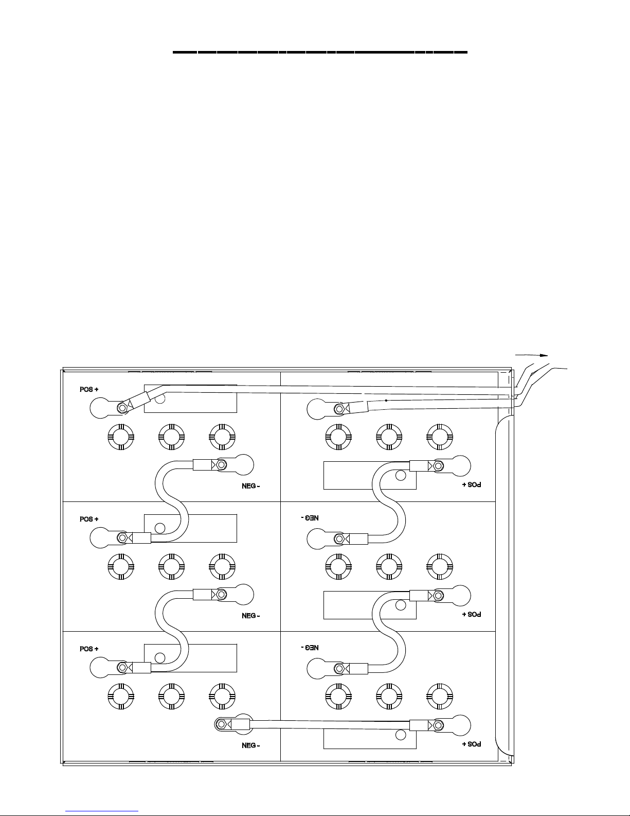
Note orientation of the positive and negative posts is critical for cables to reach.
Do not lift from battery posts, which cannot support the weight.
(See below)
36 VOLTS !
Front of machine
+
+
+
-
-
+
-
-
+
-
-
+
PAGE 29

Side Broom System
1. Flip side broom switch (A) up to lower and
engage broom. (See picture below)
A
2. To adjust side broom height, loosen locking
nut located behind screwhead (B) of screw
that is in front of scrubdeck just inside the side
wall of frame on each side of the machine.
Use 1/2" wrench to loosen locking nut.
(See picture below)
3. Turn adjustment screw (B) counter-clockwise
(loosens) to lower side brooms. Turn screw
clock-wise (tightens) to raise side brooms.
6. Picture below shows brooms to high.
7. Picture below shows brooms to low.
4. Retighten locking nut.
5. Side broom adjustment slot (C).
(See picture below)
B
8. Picture below shows brooms just right.
C
PAGE 30

Machine options
Overhead Guard
1. Your machine may be equipped with an"optional"
"Overhead Guard" (A) that helps protect the operator
from falling objects that are above the operators head.
(See picture below)
A
HD Side Doors
1. Your machine may be equipped with "optional"
"Heavy Duty Side Doors" (C) that helps protect the
machine's scrubdeck from collision damage.
(See picture below)
D
C
Non-marking tires
1. Your machine may be equipped with non marking
(D) tires, which may have reduced traction on some
floors (See picture above)
Pre-treat Soap
1. Your machine is may be with "optional" "Pre-treat
Soap" (B).
2. It helps remove stains that a normal detergent can
not get out of floor. (See picture below)
B
Industrial Battery
1. Your machine may be equipped with "optional"
"Heavy Duty Industrial Battery" and charger that
provides longer machine run time.
(See picture below)
E
On-board charger
1. Your machine may be equipped with "optional"
"On-board charger (E) that will charge your machine.
(See picture to the left)
PAGE 31

Machine options
D
A
E
B
C
Spray Hose
(A) Your machine may be equipped with "optional"
Spray hose. Permits cleaning in remote areas.
(See picture above)
Stainless Rec. tank
(B) Your machine may be equipped with "optional"
stainless steel recovery tank.
(See picture above)
Diffuser Exhaust
(C) Your machine may be equipped with "optional"
diffuser exhaust which helps reduce noise and assist in
drying the floor by dispersing air evenly to the floor. (See
picture above)
Vac Wand
(D) Your machine may be equipped with "optional"
Vacuum wand which allows you to vacuum up water
in hard to reach places.
(See picture below)
Stainless Sol. tank
(E) Your machine may be equipped with "optional"
Stainless steel Solution tank.
(See picture above)
Removable Battery box
(F) Not shown. Coming in 2008
PAGE 32

Machine options
B
C
A
Attach vac hose here
On-board Soap
1. Switch toggel switch up once for
normal soap distribution and up twice
for heavy duty soap distribution.
(See picture at top of the page item "A").
Heavy duty soap
Normal soap
No soap
Spray Hose
1. Turn on spray jet pump using the
togle switch on the central
command.
(See picture at top of page item "B" )
2. Detach srap hose from back of
machine and squieeze handel.
(See picture above)
PAGE 33
Vac Wand
1. Detach vac hose from squeegee
and attach it to the vac wand.
(See picture above)
2. Turn on vac motors using the togle
switch on the central command.
(See picture at top of page item "C" )

Maintenance
Daily Maintenance
1. Remove and clean pads or brushes. Never use soiled
pads when cleaning. Replace pads when they become
packed with residue.
2. Remove and clean debris from the float shut-off screen
and drain saver located inside the recovery tank.
3. Drain and rinse tanks thoroughly inspect vacuum hose
for any objects obstructing the air flow.
4. Raise squeegee and wiper blades with a clean cloth.
Store squeegee in the raised position to prevent damage
or setting of the blades.
5. Wipe down machine if needed. Use a nonabrasive,
non solvent cleaner, or a clean damp cloth.
6. Recharge the batteries if needed.
Weekly Maintenance
1. Check battery water level in each cell of the batteries,
and fill as needed. Always usedistilled water to refill
batteries. Batteries should be filled approximately 3/4" to 1"
above the plates. Overfilling will cause the batteries to
leak during charging. The charging process creates gas
bubbles inside the battery, which effectively increases the
volume of the electrolyte.
2. Clean battery tops to prevent corrosion.
Yearly Maintenance
1. Call your local dealer for yearly maintenance
Storing Machine
1. Be sure to flush the tanks out completely, and to drain all
water from the machine.
2. Open the recovery tank lid to promote air circulation.
3. Raise brushes and squeegee.
Checking Battery Specific Gravity
Use a hydrometer to check the battery specific gravity.
Checking Gravity
A. Hydrometer
B. Battery
Note: do not take readings immediately after adding
distilled water, if water and acid are not thoroughly mixed,
the reading may not be accurate.
Check the hydrometer against this chart
SPECIFIC GRAVITY
@ 80v F (27vC)
BATTERY CONDITION
3. Rotate brushes. Rotate the left to the right and right to
left. On cylindrical models from front to back, or end to
end if using different materials.
Monthly Maintenance
1. Check scrub head and squeegee lifting cables for
wear and spring tension.
2. Check machine for water leaks and loose nuts and
bolts.
3. Check to see if battery cables are tightened
(Tighten if needed)
4. Check parking brake
1.265
1.225
1.190
1.155
1.120
Note: if the readings are taken when the
battery electrolyte is any temperature
other than 80vF (27vC), the reading
must be temperature corrected.
To find the corrected specific gravity reading
when the temperature of the battery electrolyte
is other than 80vF (27vC): add (+) to the specific
gravity reading 0.004 (4 points), for each 10vF
(6vC) above 80v (27vC).
subtract (-) from the specific reading 0.004
(4 points), for each 10vF (6vC) below 80vF (27vC).
100% CHARGED
75% CHARGED
50% CHARGED
25% CHARGED
DISCHARGED
PAGE 34

Maintenance Service Schedule
Maintenance Sevice Schedule
Maintenance Before each work
period
Check water level of batteries after charging
add distilled water if necessary
Check that recovery tank cover seals tightly X
Visualy check for damaged or worn tires X
Check brushes or pads for proper installation X
Check vacuum hose connections X
Check that squeegee is securely attached
and properly adjusted
Check that side squeegees are properly
adjusted
Check for attached drain hose, plug and
caps
Check parking brake and steering for proper
operation
Inspect vacuum filter for debris X
Clean out solution tank and filter, check flow X
Run vacuum motors to dry X
Clean brushes or pads and check for wear X
Clean main and side squeegee blades and
check for wear
Clean out recovery tank and vacuum filter X
Clean and inspect flow shutoff X
Clean outside of tanks and check for
damages
Store with tank covers open X
Charge batteries X
Check side squeegee for wear X
Clean off top of batteries X
Check battery cells with hydrometer X
Inspect scrub deck skirt X
Clean solution strainer X
Check battery connections are tight X
Check parking brake adjustment X
Check battery case and battery
compartment
Check brake for damage or wear X
Clean pivot points on squeegee and scrub
deck
Check all motors for carbon brush wear X
Check motor commutators X
Check steering chain tensioner X
NOTE: Traction drive, wheels and batteries should be serviced based on traction drive
hour meter. The scrub brush hour meter should be used for all other service schedule items.
X
X
x
X
X
After each work
period
X
X
50 hrs 100 hrs 200 hrs
X
X
PAGE 35

Preventative Maintenance Records
MACHINE INFORMATION
One Touch Switch
CUSTOMER INFORMATION
CUSTOMER
ADDRESS
CITY STATE ZIP CODE
MODEL # SERIAL #
WORK ORDER# HOUR METER:
BATTERY CONDITION Cell #1 Cell #2 Cell #3
Battery # 1 Hydrometer Reading
Battery # 1 Water Condition
Battery # 2 Hydrometer Reading
Battery # 2 Water condition
Battery # 3 Hydrometer Reading
Battery # 3 Water Condition
Battery # 4 Hydrometer Reading
Battery # 4 Water condition
Battery # 5 Hydrometer Reading
Battery # 5 Water Condition
Battery # 6 Hydrometer Reading
Battery # 6 Water Condition
Clean Battery Tops. Check Battery Cable and Terminal Condition
NOTES:
BRUSH CONDITION
Scrub Brush Fiber Length Rotated Brushes
Brush Drive Sockets Good Worn Needs Replacement
Drive Hubs Good Worn Needs Replacement
Side Broom Condition Good Worn Needs Replacement Rotated Side to Side
CHECK OPERATION AND CONDITION OF: IN SPEC REPAIR PROBLEM
Steering wheel Tilt Mechanism
Key Switch
Horn
Head Light
LCD Display
Page Button
Brush Pressure Button
Brush Pressure Managers Lock Out
Foot Pedal
Reverse Switch
Back Up Alarm
PAGE 36

Preventative Maintenance Records
CHECK OPERATION AND CONDITION OF: IN SPEC REPAIR PROBLEM
Brush Switch
Solution Potentiometer
Solution Solenoid
Solution Drain Valve
Low Solution Light
Brush Deck Lift System
Brush Motors & Motor Brushes
Vacuum Switch
Vacuum Motor performance
Off-Board Vac Switch
Squeegee Lift System
Squeegee Adjustment
Squeegee Blades
High Recovery Light
High Recovery Alarm
Drain Hose and Plug
Side Broom Operation
Spray Jet Switch
Spray Jet Pump, Hose & Nozzle
Strobe Light
Battery Charger Connectors
Battery Charger
CLEAN AND/OR LUBRICATE IN SPEC REPAIR PROBLEM
Solution Filter
Squeegee pivot points & Knobs
Scrub Deck Linkage
Steering Chain
VISUALLY INSPECT: IN SPEC REPAIR PROBLEM
Solution Tank Condition
Recovery Tank & Lid Condition
Drain Saver
Vacuum floats
Vacuum Filter
Vacuum Motor Brushes
Vacuum Hoses
Solution Hoses
Blade retainers & hardware
Squeegee Wheels
Brush skirts
Brush Motor Brushes
Brush or Pad Driver Condition
Drive Wheel Condition
Rear Wheels Condition
All Rollers
COMMENTS
Technician's Name
Technician's Signature Date
Customer's Name:
Customer's Signature Date
PAGE 37
Troubleshooting Central Command
Note: this machine is operated by a sophisticated electronic "controller" that has many fail-safes within it. It
self-analyzes problems and flashes a four-digit alpha-numeric code of what is wrong in the LCD window.
Most of these codes require a technician attention. You should not attempt repairs you are unfamiliar with, especially if
you are not authorized to work on this equipment.
The complete list of codes is published in the simplified electronic troubleshooting manual, which is available to
authorized and certified distribution technicians. However, we have included the basic codes that you can usually
resolve yourself.
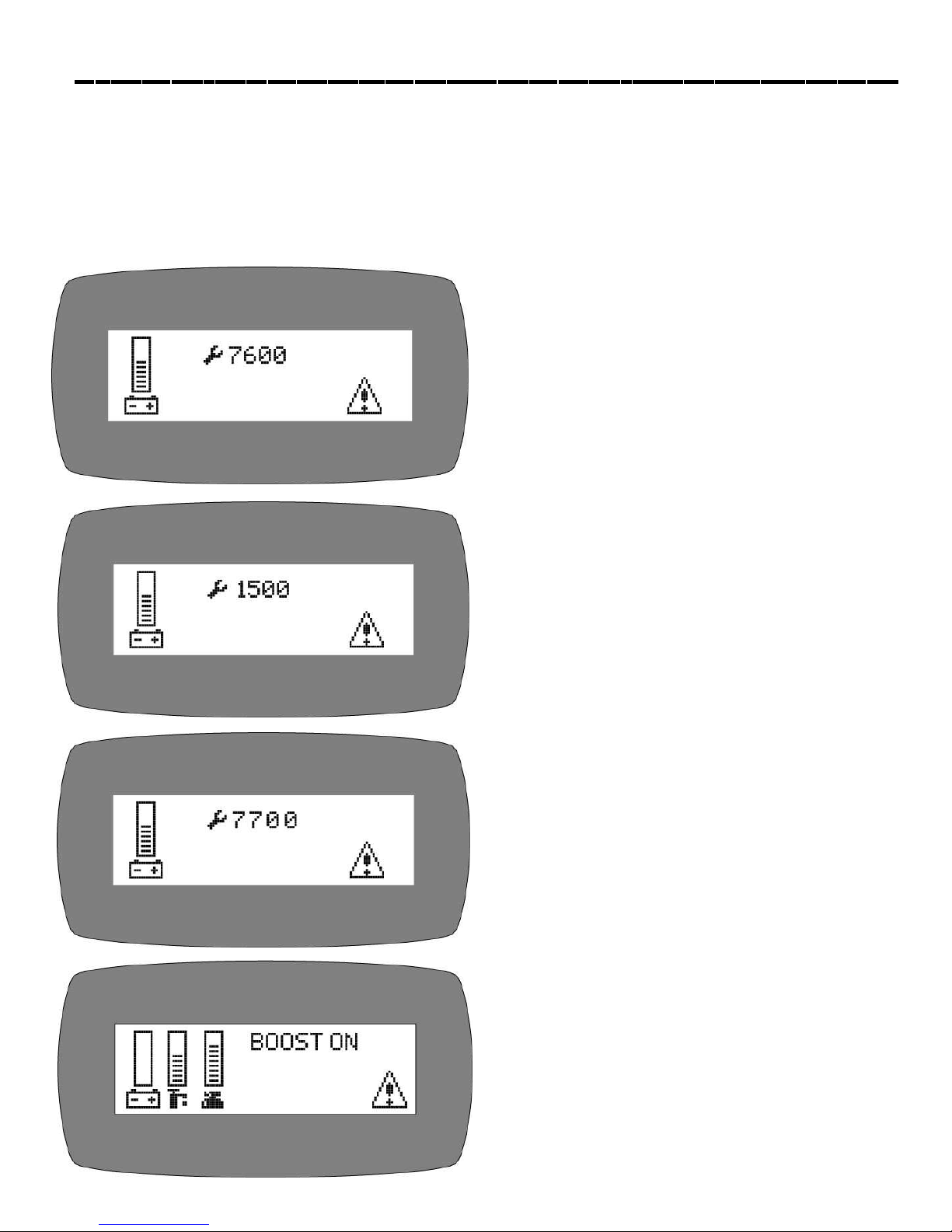
1. 7601 and 7602 Error. Scrub deck current over load.
This can occur when driving over a bump in the floor. To
restart, turn off the key and turn it on again. To avoid this
error, either slow down on bumpy parts of the floor, or
reduce down pressure on the pads.
2. 1500 Error. There is an open in the parking brake
circuit. Check the parking brake wiring and the parking
brake coil to find the open circuit.
3. 7700, 7701, 7702, and 7703 Error. The vacuum motor
has exceeded their authorized power limits. Turn off key
and turn on again to clear.
4. BOOST ON Allows front wheel drive to draw more
power when needed to climb ramps for 30 seconds.
PAGE 38

Troubleshooting Central Command
5. 7700. Vacuum motor circuit is open.
6. Throttle error. You pressed the foot pedal before
turning on the key. Turn off the key and try again, leaving
foot off of the pedal.
7. 2C00 and 2C01 error. Low voltage warning. Voltage
has dropped down below the minimum required to
operate the machine. If you wait a few minutes, the
batteries may come up in voltage, allowing you to drive
very slowly to the recharge station. If not, you will have to
release the parking brake (on the front wheel, pull lever
toward the front of the machine to release) and push the
machine to recharging station. You must disconnect the
traction motor! (+ cable first)
8. 7802 error. The traction motor pulled excessive current
perhaps running a ramp for more than the 60 seconds
allowing for this. Turn off the key, turn on again, and
continue. You should not use this machine to climb ramps
so steep and so long that this code comes up repeatedly,
or you could overheat the traction motor.
9. All other error codes. Turn off the key, and disconnect the positive battery cable from the batteries for more than
one minute (the time is needed to drain the controler on-board capacitor). Reconnect cables, being sure that it is
tight. Too loose and you will burn battery. If you over tighten the cables you can damage the battery lead terminal.
Try again.
10. If the problems cannot be solved by any of this solution, call your local dealer service department.
PAGE 39

Troubleshooting
Problem
No power, nothing operates
Brush motor(s) do not operate
Drive motor does not operate
Vacuum motor does not operate
Cause
Faulty key switch
Batteries need charging
Faulty battery
Loose battery cable
Main circuit breaker tripped
Brush deck is not down
Foot pedal is not depressed
Brush circuit breaker tripped
Carbon brushes worn
Faulty brush motor or wires
Recharge switch misadjusted
Faulty speed controller or wires
Faulty drive motor
Faulty wiring
Carbon brushes worn
Squeegee is in the up position
Faulty vacuum switch
Vacuum circuit breaker tripped
Faulty vacuum motor
Solution
Contact local servicing dealer
See charging batteries
Replace battery
Tighten loose cable
Wait 5 minutes for auto reset
Determine cause and correct
Put brush deck down
Engage foot pedal
Wait 5 minutes for auto reset
Determine cause and correct
Contact local servicing dealer
Contact local servicing dealer
Contact local servicing dealer
Contact local servicing dealer
Contact local servicing dealer
Contact local servicing dealer
Contact local servicing dealer
Rotate squeegee lift lever down
Try operating "white” toggle
Wait 5 minutes for auto reset
Determine cause and correct
Contact local servicing dealer
Drive motor runs incorrectly
Insufficient solution flow
Faulty speed controller or wires
Faulty potentiometer
Loose wires
Solution tank low
Flow knob turned down
Solution filter clogged
Solution line clogged
Solution valve clogged
PAGE 40
Contact local servicing dealer
Contact local servicing dealer
Contact local servicing dealer
Refill solution tank, drain recovery
tank
Move lever to on
Remove cover and clean
Remove and blow out with
compressed air
Remove cover and clean

Troubleshooting
Problem
No solution flow
Poor water recovery
Poor water recovery on turns
Cause
No solution in tank
Solution valve off
Solution switch off
Solution screen clogged
Faulty solution solenoid
Faulty solution switch
Recovery tank is full
Ball/screen in recovery
Tank is clogged
Vacuum hose is clogged
Squeegee is clogged
Squeegee blade is worn
Faulty vacuum hose
Vacuum motor gasket torn
Tank gasket faulty
Drain plug loose
Vac motor faulty
Battery charge low
Wipers worn
Wipers chatter
Squeegee swing is binding
Incorrect squeegee size
Solution
Fill solution tank
Rotate lever to on
Turn solution switch on
Remove and clean screen
Contact local servicing dealer
Contact local servicing dealer
Empty recovery tank
Remove screen and clean
Remove debris
Remove debris
Rotate or replace blades
Contact local servicing dealer
Contact local servicing dealer
Contact local servicing dealer
Tighten lid
Contact local servicing dealer
Charge batteries overnight
Replace wiper material
Tighten pivot points
Contact local servicing dealer
Contact local servicing dealer
Rear tires noisy
Poor traction
Short run time
Bearing dry
Faulty hubs
Excessive brush pressure
Worn drive tire
Heavy soap concentration
Batteries run down
Batteries still down
Batteries low on water
Batteries over cycled
PAGE 41
Grease bearings
Contact local servicing dealer
Reduce pressure with switch
Contact local servicing dealer
Charge batteries twice
Contact local servicing dealer
Fill with distilled water to 3/4"
above the lead plates
Contact local servicing dealer

Model
XR-34D / XR-40D / XR-34C
XR-40C / XR-46C
Machine Parts Section
Machine parts illustration
Front wheel drive
Side brooms (optional)
Front wheel side brooms and rollers
Disk deck
Shrouds
Cylindrical wipers
Cylindrical decks
Cylindrical doors
Attaching decks
Squeegee trail arm
53" Squeegee
60" Squeegee
Squeegee trail arm and rear axle
Dual vac motors
Vac motors and solution hoses
Tank lid
Tank baffle
Solution/Recovery tank
Attaching tanks
Standard batteries and seat
Optional battery and seat
Central command
Steering tower assembly
Central command and steering tower
Doors (optional)
Over head guard (optional)
Water jet kit (optional)
Vac wand kit (optional)
Page 42-43
Page 44-45
Page 46-47
Page 48-49
Page 50
Page 51
Page 52-53
Page 54-55
Page 56-57
Page 58-59
Page 60-61
Page 62-63
Page 64-65
Page 66-67
Page 68-69
Page 70-71
Page 72-73
Page 74-75
Page 76-77
Page 78-79
Page 80-81
Page 82-83
Page 84-85
Page 86-87
Page 88-89
Page 90-91
Page 92
Page 93

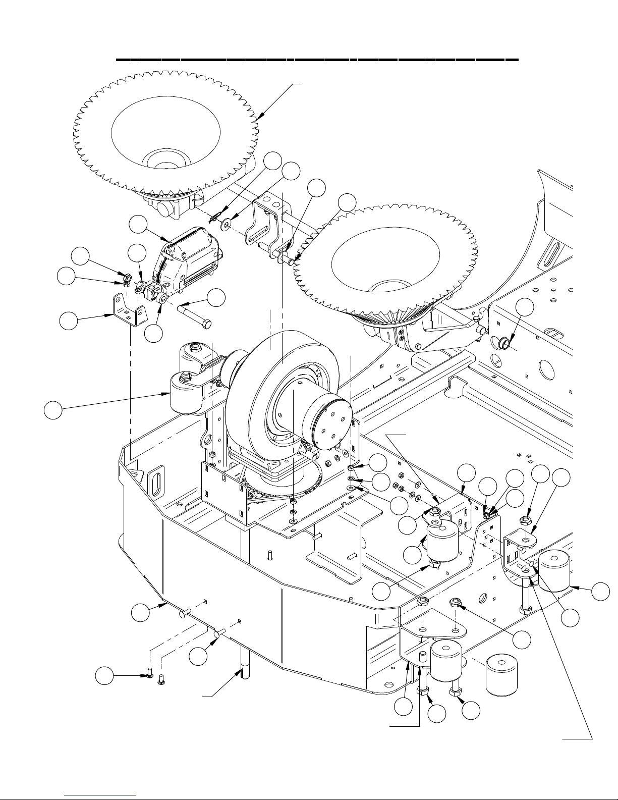
Front wheel drive
35
19
21
17
16
17
13
34
22
23
29
31
33
5
8
7
9
24
11
10
9
7
8
27
32
30
2
26
31
18
14
1
3
4
12
12
6
15
TO ORDER COMPLETE DRIVE
UNIT USE PART #370-7310
28
25
TO ORDER MOTOR SEPARATELY
USE PART #370-7311
20
TO ORDER WHEEL SEPARATELY
USE PART # 370-7315
TO ORDER BRAKE SEPARATELY
USE PART #370-7323
PAGE 42

Front wheel drive
Item Part No. Part Description Qty
1 250-7314 60 TOOTH STEERING SPROCKET 1
2 250-7320 12" DROP PLATE 1
3 250-7327 STEERING CHAIN 1
4 250-7332 STEERING SHAFT 1
5 275-7120 STEERING SHAFT, LOWER 1
6 290-2780 TERMINAL BOOT, BLACK 1
7 37-7317 TAPERED ROLLER BEARING 2
8 37-7318 BEARING CAP 2
9 37-7319 STEERING SHAFT SEAL 2
10 37-7320 PRE LOAD SLEEVE 1
11 37-7321 SLOTTED NUT, 2.0 - 12 1
12 370-7326 PIVOT PLATE 2
13 5-826 10 TOOTH SPROCKET 1
14 5-831 MASTER LINK 1
15 8-278 TERMINAL BOOT, RED 1
16 8-723 BEARING BLOCK 1
17 8-723B BEARING 2
18 H-0172951 HCS 3/8"- 24 X 2 1/2" S/S 7
19 H-25435 SSS CP 5/16" X 1/4" 1
20 H-33372 SHAFT COLLAR, 3/8" ID 6
21 H-33376 SET SCREW SHAFT COLLAR, 3/4" ID X 9/16 LG 1
22 H-68013 SNAPRING 5/8" 1
23 H-70003 HCS 1/4"- 20 X 3/4" SS 1
24 H-70103 HCS 3/8"-16 X 3/4" SS 2
25 H-70109 HCS 3/8"- 16 X 1-1/2" SS 4
26 H-70710 HN 1/4"- 20 SS 1
27 H-70712 HN 3/8"-16 SS 2
28 H-70732 HN 3/8"- 24 SS 1
29 H-71013 FNW 1/4" X 5/8" SS 4
30 H-71017 FW 3/8" X 7/8" SS 2
31 H-71063 LW 1/4" SS 5
32 H-71067 LW 3/8" SS 2
33 H-73754 BHSCS 1/4 - 20 X 3/4" SS 4
34 H-K1432 3/16" X 1/2" KEY 1
35 M-9381T24 S-HOOK 1
PAGE 43
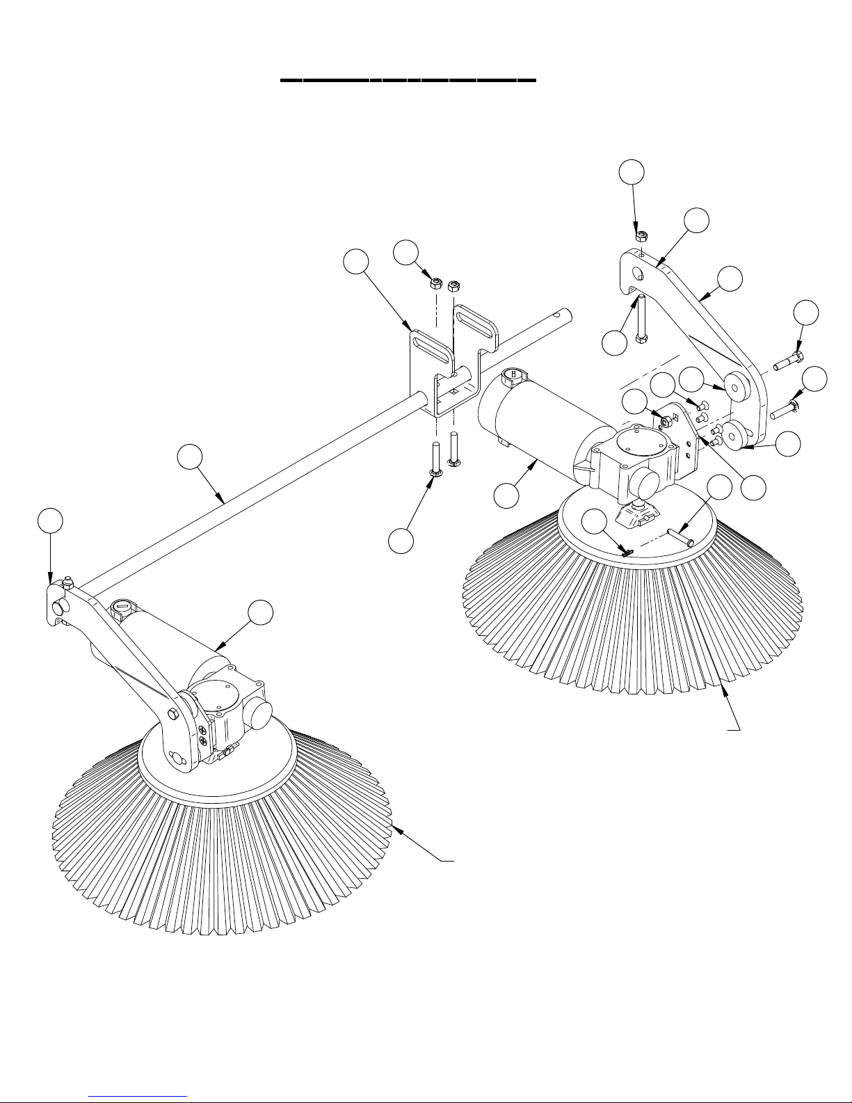
Side Brooms
10
3
5
6
4
1
10
13
3
9
11
8
12
10
16
2
15
7
14
8
4-402 SIDE BROOM POLYPROPYLENE
4-402S SIDE BROOM POLY STEEL
4-402 SIDE BROOM POLYPROPYLENE
4-402S SIDE BROOM POLY STEEL
PAGE 44

Side Brooms
Item Part No. Part Description Qty.
1 250-0220 (RH) SIDE BROOM MOTOR, 36V 106 RPM 1
2 250-0221 (LH) SIDE BROOM MOTOR, 36V 106 RPM 1
3 250-4420 SIDE BROOM LIFT ARM (LH) 1
4 250-4421 SIDE BROOM LIFT ARM (RH) 1
5 370-4422 SIDE BROOM PIVIOT 1
6 370-4620 SIDE BROOM AXLE SHAFT 1
7 390-1170 SIDE BROOM MTG PLATE 2
8 4-446 GROMMET-3/8 ID X 1-1/2 OD X .375 4
9 H-70059 HCS 5/16"- 18 X 1-1/2" 2
10 H-70861 NYLOK 5/16" - 18 SS 8
11 H-71183 HCS 5/16"- 18 X 2-1/2" FULL THREAD SS 2
12 H-72704 FHP 1/4"- 20 X 1/2" SS 8
13 H-74401 CB 5/16"- 18 X 1-3/4" SS 2
14 H-74432 CB 5/16"- 18 X 1-1/2" SS 2
15 H-RUE8 RUE RING COTTER 2
16 H-ZCP44 1/4" X 1 1/2" CLEVIS PIN 2
PAGE 45
Front Wheel & Side Brooms
24
4
SIDE BROOM ASSEMBLY
FOR INDIVIDUAL PARTS
SEE SIDE BROOM PAGE
19
19
10
9
16
3
2
11
11
13
16
20
290-1128 USED WITH
34" DECK MACHINES
5
15
18
14
17
21
8
14
1
6
23
22
FRONT WHEEL DRIVE ASSEMBLY
FOR INDIVIDUAL PARTS
SEE FRONT WHEEL DRIVE PAGE
12
370-1126 USED WITH
40" CYLINDRICAL DECK MACHINES
PAGE 46
2
7
12
21-1126 USED WITH
40" DISK DECK MACHINES
12
2
21
14

Front Wheel & Side Brooms
Item Part No. Part Description Qty.
1 21-1126 ROLLER BRACKET 4
2 21-1127 ROLLER 8
3 250-1102 SCRUB DECK LIFTING BRACKET 1
4 250-2240 2" STROKE 36V ACTUATOR 450 LB LOAD 1
5 290-1128 LOWER ROLLER BRACKET 2
6 370-1100 MAIN FRAME 1
7 370-1126 DOUBLE ROLLER BRACKET (40") 1
8 4-4230 3/4" X 1" X 1/2" FLG BEARING 2
9 H-0129159 JNYL, 1/2"-13, 18-8 SS 1
10 H-02783 1/2" X 4" CLEVIS PIN 1
11 H-03660 .50 ID SHAFT COLLAR WITH SET SCREW 2
12 H-11319 HB 5/8"- 11 X 4" 8
13 H-13217 HCS 1/2"-13 X 3-1/2" SS 2
14 H-37038 JNYL 5/8"- 11 8
15 H-70860 NYLOK 1/4"- 20 SS 9
16 H-70861 NYLOK 5/16" - 18 SS 8
17 H-71013 FNW 1/4" X 5/8" SS 8
18 H-71015 FW 5/16" X 3/4" SS 7
19 H-71021 FW 1/2" USS 2
20 H-71065 LW 5/16" SS 6
21 H-74419 CB 1/4"- 20 X .75" SS 22
22 H-74429 CB 5/16"- 18 X 3/4" SS 2
23 H-74430 CB 5/16"- 18 X 1" SS 8
24 H-RUE22 1/2" RUE RING COTTER 1
PAGE 47

Disk Decks
45
43
32
39
14
39
45
39
26
45
26
39
7
8
39
32
42
12
19
39
33
7
33
22
10
27
27
8
24
39
17
48
22
20
5
45
35
38
3
15
21
48
39
(RH) 34 INCH SHROUD
FOR INDIVIDUAL PARTS
SEE SHROUD PAGE
42
46
31
10
25
40
28
18
34
39
6
4
40
25
11
31
40
33
37
36
23
36
39
6
6
47
46
27
40
40
39
30
36
33
39
40
29
36
39
6
37
47
27
1
44
40
9
2
16
13
41
42
42
PAGE 48

Disk Decks
Item Part No. Part Description Qty.
1 21-5000 BRUSH DRIVER 2
2 250-1084 SHROUD ADJUSTMENT KNOB 4
3 250-1103 DISK SCRUB DECK BRACKET 1
4 250-1265 SCRUB ARM BRACKET 2
5 250-2210 4" STROKE 36V ACTUATOR 1000 LB LOAD 1
6 290-1233 3/8" ID, 1/2" OD, 1/4" LG BEARING 8
7 290-1245 3/8" ID, 1/2" OD, 3/8" LG, FLANGE BEARING 4
8 290-1247 BRONZE THRUST BEARING, .50" ID X 1.0" OD X 1/16" TH 4
9 290-5787 STAR KNOB, 3/8-24 THREAD 4
10 290-9584 ROD END, 3/8-24 LEFT HAND THREAD 2
11 290-9585 ROD END, 3/8-24 RIGHT HAND THREAD 2
12 370-0015 FRONT DISK DECK CURTAIN 1
13 370-0016 REAR DISK DECK CURTAIN 1
14 370-1081 SLEEVE BEARING 1
15 370-1800 1/2" ID X 14" LG WIRE REINF. CLEAR TUBE 2
16 370-4020 DISK SCRUB DECK 1
17 370-4022 ACTUATOR ADJUSTMENT BRACKET 1
18 370-9584 ADJUSTABLE LATERAL ARM BODY 2
19 370-9586 LATERAL ARM (DISK) 1
20 390-2222 MOTOR 36V 1.0 HP X 200 RPM 2
21 5-446 1/2 " PLASTIC BARB TEE 1
22 5-447 1/2 NPT X 1/2" BARB ELBOW 2
23 H-0171004 JNYL 3/8- 24 SS 4
24 H-0172940 HCS 3/8"- 24 X 4.5" FULL THREAD SS 1
25 H-02949 3/8 ID X 5/8 OD SHIM 4
26 H-04804 3/8" X 5" CLEVIS PIN 2
27 H-07005 1/2" NPT LOCKNUT 4
28 H-36956 LH HX JAM .375-24 SS 2
29 H-70055 HCS 5/16"- 18 X 1" SS 2
30 H-70103 HCS 3/8"-16 X 3/4" SS 8
31 H-70109 HCS 3/8"- 16 X 1-1/2" SS 4
32 H-70110 HCS 3/8"- 16 X 1-3/4" SS 4
33 H-70712 HN 3/8"-16 SS 6
34 H-70832 HX JAM .375-24 SS 2
35 H-70861 NYLOK 5/16" - 18 SS 4
36 H-70862 NYLOK 3/8"-16 SS 8
37 H-71013 FNW 1/4" X 5/8" SS 5
38 H-71015 FW 5/16" X 3/4" SAE SS 4
39 H-71017 FW 3/8" X 7/8" SS 20
40 H-71067 LW 3/8" SS 22
41 H-72949 HCS 3/8"- 24 X 2" SS FULL THREADED 4
42 H-73753 BHSCS 1/4 - 20 X 5/8" SS 4
43 H-73754 BHSCS 1/4 - 20 X 3/4" SS 1
44 H-74429 CB 5/16"- 18 X 3/4" SS 4
45 H-96544 SPRING, 4-1/8" LG X 9/16" OD (42E) 4
46 H-98025 FW 3/8" GRADE 8 4
47 H-NJ04C JNYL 1/4" - 20 SS 5
48 H-RUE14 3/8" RUE RING COTTER 2
PAGE 49

Shrouds
34" LEFT HAND SHROUD SHOWN PART # 370-1136
34" RIGHT HAND SHRAOUD USE PART # 370-1135
40" LEFT HAND SHROUD USE PART # 370-1138
40" RIGHT HAND SHROUD USE PART # 370-1137
7
1
5
5
4
3
7
7
7
4
7
4
7
4
7
4
7
4
7
4
6
6
6
370-1139L LINATEX SHROUD WIPER
370-1139G GUM RUBBER SHROUD WIPER
TO ORDER COMPLETE (LH)
34" SHROUD ASSEMBLY USE
PART # 370-1136C
FOR 40" (LH) SHROUD ASSEMBLY USE
PART # 370-1138C
Item Part No. Part Description Qty.
1 370-0018 SHROUD CURTAIN 1
2 370-1140 SHROUD CURTAIN BAND (34" & 40") 1
3 5-849 RECESSED HANDLE 1
4 H-71013 FNW 1/4" X 5/8" SS 7
5 H-73752 BHSCS 1/4 - 20 X 5/8" SS 2
6 H-74419 CB 1/4"- 20 X .75" SS 7
7 H-NJ04C JNYL 1/4" - 20 SS 9
6
6
TO ORDER COMPLETE (RH)
34" SHROUD ASSEMBLY USE
6
PART # 370-1135C
FOR 40" (RH) SHROUD ASSEMBLY USE
6
2
PART # 370-1137C
PAGE 50
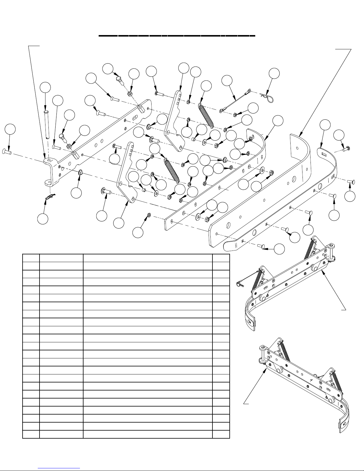
Cylindrical wiper
11
LH WIPER HORIZONTAL ARM USE PART # 370-1232
RH WIPER HORIZONTAL ARM USE PART # 370-1231
3
10
6
13
7
15
10
6
11
2
7
14
17
16
13
17
21
8
20
17
2
14
3
18
17
17
17
17
17
21
370-1135L LINATEX SIDE WIPER
370-1135G GUM RUBBER SIDE WIPER
22
1
16
17
17
8
18
4
17
17
2
17
17
9
19
9
19
12
5
12
12
12
12
Item Part Number Part Description Qty
1 21-4060 6" LANYARD 1
2 290-1233 3/8" ID, 1/2" OD, 1/4" LG BEARING 4
3 370-1233 SHROUD VERTICAL ARM 2
4 370-1234 INNER CYLINDRICAL WIPER BAND 1
5 370-1236 OUTER CYLINDRICAL WIPER BAND 1
6 H-70057 HCS 5/16"- 18 X 1-1/4" 2
7 H-70711 HN 5/16"- 18 SS 2
8 H-71015 FW 5/16" X 3/4" SAE SS 2
9 H-71017 FW 3/8" X 7/8" SS 2
10 H-72710 FHP 1/4"- 20 X 1" SS 2
11 H-73908 FHSCS 5/16"- 18 X 1" SS 2
12 H-74419 CB 1/4"- 20 X .75" SS 6
13 H-74420 CB 1/4"- 20 X 1.0" SS 2
14 H-74436 CB 3/8"- 16 X 1.0" SS 2
15 H-923902 3/8" X 4" CLEVIS PIN 1
16 H-96544 SPRING, 4-1/8" LG X 9/16" OD (42E) 2
17 H-NJ04C JNYL 1/4" - 20 SS 14
18 H-NJ05C JNYL 5/16"- 18 SS 2
19 H-NJ06C JNYL 3/8- 16 SS 2
20 H-RUE14 3/8" RUE RING COTTER 1
21 M-6391K403 .312 ID X .375 OD X .25 LG BEARING SLEEVE 2
22 M-92391A044 HAIRPIN, 5/16" - 3/8" X 1-7/16" S/S 1
12
TO ORDER COMPLETE
(LH) WIPER ASSEMBLY
USE PART # 370-1232C
TO ORDER COMPLETE
(RH) WIPER ASSEMBLY
USE PART # 370-1231C
PAGE 51

Cylindrical decks
34" HOPPER RAIL SHOWN
40" HOPPER RAIL USE PART # 430-8320
A
34" BRACKET SHOWN
40" BRACKET USE PART # 370-1268
34
31
25
54
10
42
4
42
34" DECK SHOWN
40" DECK USE PART # 370-9040
9
51
56
29
1
14
54
10
42
31
34
10
42
44
38
31
5
21
34" HOPPER SHOWN
20
23
46
18
22
58
41
42
36
38
38
50
13
32
53
42
42
39
3
11
28
51
37
55
47
40
43
48
12
28
40" HOPPER USE PART # 370-9054
15
56
54
51
49
42
26
17
24
57
42
52
33
56
2
45
16
27
30
7
30
30
6
30
8
35
42
19
10
42
10
44
38
10
31
DETAIL A
PAGE 52

Cylindrical decks
Item Part No. Part Description Qty.
1 21-1127 ROLLER 1
2 250-0001 RETAINER PIN 2
3 250-1230 SHROUD HINGE 2
4 250-1265 SCRUB ARM BRACKET 2
5 250-2240 2" STROKE 36V ACTUATOR 450 LB LOAD 1
6 253-8215 TIMING SPROCKET 32 TOOTH 2
7 253-8225 TIMING SPROCKET 68 TOOTH 2
8 253-8230 565-5M-25 HI-PERFORMANCE PD PLUS BELT 2
9 253-9002 MOTOR ADJ BRACKET 2
10 290-1233 3/8" ID, 1/2" OD, 1/4" LG BEARING 12
11 290-1245 3/8" ID, 1/2" OD, 3/8" LG, FLANGE BEARING 4
12 370-0018 DISK SHROUD CURTAIN (34") 1
13 370-1237 ROLLER BRACKET 1
14 370-1267 34" CYLINDRICAL LIFTING BRACKET 2
15 370-2220 MOTOR 36V 1.5 HP X 350 RPM, 2.2" SHAFT 2
16 370-8240A BEARING HOUSING/BEARING 2
17 370-8370 BRUSH DRIVER 2
18 370-9003 CYLINDRICAL LIFTING BRACKET 1
19 370-9020 370 CYL. LATERAL ARM 1
20 370-9034 CYLINDRICAL BRUSHHEAD, 34" 1
21 370-9053 34" HOPPER 1
22 390-7712 COMPRESSION SPRING 4
23 390-8320 HOPPER RAIL 1
24 5-849 RECESSED HANDLE 1
25 7-843 ADJUSTABLE LATERAL ARM 2
26 H-00270 3/16" X 3/4" KEY 2
27 H-01125 3/16" X 1" KEY 2
28 H-0171004 JNYL 3/8- 24 SS 4
29 H-11319 HB 5/8"- 11 X 4" 1
30 H-25306 SSS CP #10-32 X 1/4" 8
31 H-37024 NYLOK 3/8"-16 8
32 H-37038 JNYL 5/8"- 11 1
33 H-70105 HCS 3/8"- 16 X 1" SS 8
34 H-70109 HCS 3/8"- 16 X 1-1/2" SS 4
35 H-70110 HCS 3/8"- 16 X 1-3/4" SS 4
36 H-70113 HCS 3/8"- 16 X 2-1/2" SS 1
37 H-70142 HCS 3/8"- 24 X 1" S/S 2
38 H-70712 HN 3/8"-16 SS 6
39 H-70861 NYLOK 5/16" - 18 SS 16
40 H-71013 FNW 1/4" X 5/8" SS 2
41 H-71015 FW 5/16" X 3/4" SAE SS 10
42 H-71017 FW 3/8" X 7/8" SS 28
43 H-71063 LW 1/4" SS 3
44 H-71067 LW 3/8" SS 4
45 H-72682 FHP #10-32 X 1/2" SS 8
46 H-72684 FHP 10-32 X 3/4" SS 6
47 H-73459 SHCS 1/4-20 X 1/2 SS 8
48 H-73752 BHSCS 1/4 - 20 X 5/8" SS 2
49 H-744?? CB 5/16"- 18 X 1/2" SS 8
50 H-74417 CB 1/4"- 20 X .5" SS 2
51 H-74429 CB 5/16"- 18 X 3/4" SS 14
52 H-90895 WASHER, SERRATED BELLEVILLE, 3/8", S/S 8
53 H-923903 3/8" X 4" CLEVIS PIN 2
54 H-98025 FW 3/8" GRADE 8 12
55 H-K14320 3/16" X 1 1/4" KEY 2
56 H-NJ04C JNYL 1/4" - 20 SS 10
57 H-NJ05C JNYL 5/16"- 18 SS 6
58 H-RUE14 3/8" RUE RING COTTER 2
PAGE 53
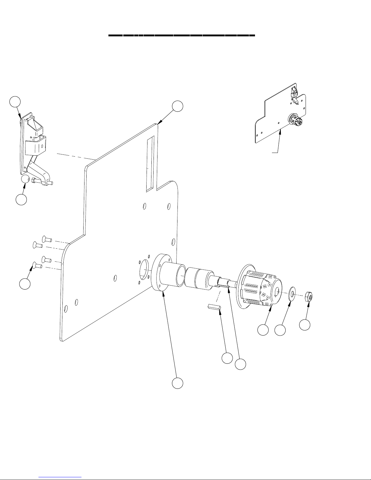
Cylindrical door
5
9
1
TO ORDER WHOLE DOOR
ASSEMBLY USE
PART # 370-9021
4
7
8
6
3
2
10
PAGE 54

Cylindrical door
Item Part No. Part Description Qty.
1 370-9022 DRIVE COVER 1
2 1-305 BEARING HOUSING 1
3 370-8241 IDLER BEARING 1
4 H-72682 FHP #10-32 X 1/2" SS 4
5 5-130 DOOR LATCH 1
6 H-00270 3/16" X 3/4" KEY 1
7 370-8370 BRUSH DRIVER 1
8 H-71017 FW 3/8" X 7/8" SS 1
9 5-100 GROMMET 1
10 H-0171004 JNYL 3/8- 24 SS 1
PAGE 55

Attaching decks
34" DISK DECK SHOWN
SEE DISK DECK PAGE
FOR INDIVIDUAL PARTS
8
34" CYLINDRICAL DECK SHOWN
SEE CYLINDRICAL DECK PAGE
FOR INDIVIDUAL PARTS
2
10
7
10
7
10
7
10
7
8
11
14
13
7
5
9
6
7
5
9
7
15
3
4
1
13
12 12
8
9
12
PAGE 56

Attaching decks
Item Part No. Part Description Qty.
1 250-1102 SCRUB DECK LIFTING BRACKET 1
2 370-0019 FRONT WALL CURTAIN 1
3 370-1100 MAIN FRAME 1
4 H-0156776 1/2" X 3.5" CLEVIS PIN 1
5 H-32258 RUBBER LOOP CLAMP, 1.0" #16 2
6 H-3225T RUBBER LOOP CLAMP, 1-1/2" 1
7 H-70860 NYLOK 1/4"- 20 SS 7
8 H-70861 NYLOK 5/16" - 18 SS 16
9 H-70925 KN 1/4-20 S/S 3
10 H-71013 FNW 1/4" X 5/8" SS 4
11 H-74419 CB 1/4"- 20 X .75" SS 3
12 H-74420 CB 1/4"- 20 X 1.0" SS 3
13 H-74429 CB 5/16"- 18 X 3/4" SS 6
14 H-9307K74 GROMMET, 1" ID X 1-3/4" OD BUNA-N 3
15 H-RUE22 1/2" RUE RING COTTER 1
PAGE 57
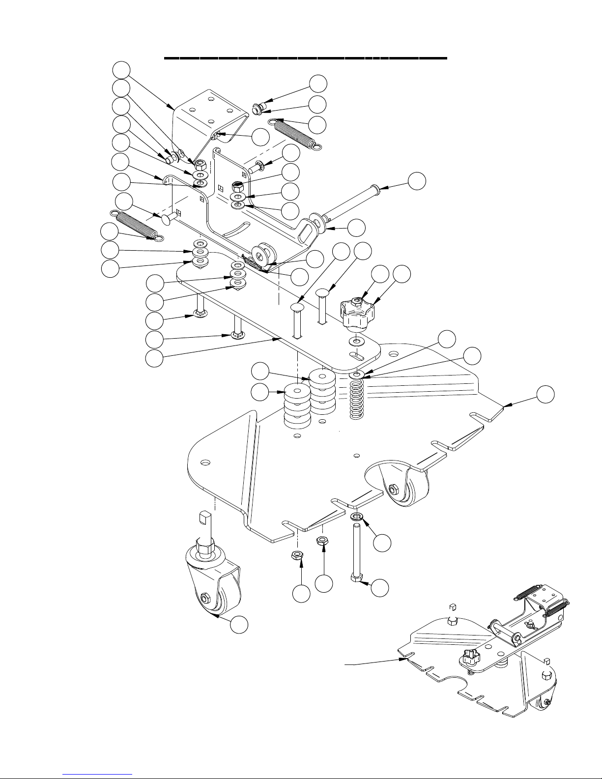
3
13
2
Squeegee trail arm
26
2
21
22
22
26
14
4
12
17
22
22
18
18
5
23
7
7
17
13
14
12
25
21
15
19
15
19
10
9
1
14
11
6
24
24
8
TO ORDER COMPLETE
SQUEEGEE TRAIL ARM
ASSEMBLY USE
PART # 370-7155
PAGE 58
16
20

Squeegee trail arm
Item Part No. Part Description Qty.
1 21-7205 STAR KNOB 1
2 290-1233 3/8" ID, 1/2" OD, 1/4" LG BEARING 2
3 370-5002 SQUEEGEE DRAG BRACKET 1
4 370-7140 SQUEEGEE SWING PLATE 1
5 370-7150 SQUEEGEE TRAIL ARM 1
6 370-7610 SQUEEGEE TRIANGLE PLATE 1
7 4-446 GROMMET-3/8 ID X 1-1/2 OD X .375 6
8 430-7570 CASTER 2
9 H-0171004 JNYL 3/8- 24 SS 1
10 H-02783 1/2" X 4" CLEVIS PIN 1
11 H-111 SPRING, 1/2" ID X 2-1/2" LG 1
12 H-4440024 FW 3/8" X 3/4" NYLON 4
13 H-70862 NYLOK 3/8"-16 SS 2
14 H-71017 FW 3/8" X 7/8" SS 4
15 H-71021 FW 1/2" USS 2
16 H-71067 LW 3/8" SS 1
17 H-74429 CB 5/16"- 18 X 3/4" SS 2
18 H-74438 CB 3/8"- 16 X 1-1/2" SS 2
19 H-74439 CB 3/8"- 16 X 2.0" SS 2
20 H-92865A227 HCS 3/8"- 24 X 3.5" SS 1
21 H-96544 SPRING, 4-1/8" LG X 9/16" OD (42E) 2
22 H-98025 FW 3/8" GRADE 8 4
23 H-NJ05C JNYL 5/16"- 18 SS 2
24 H-NJ06C JNYL 3/8- 16 SS 2
25 H-RUE22 1/2" RUE RING COTTER 1
26 M-6391K403 .312 ID X .375 OD X .25 LG BEARING SLEEVE 2
PAGE 59

53" Squeegee
TO ORDER COMPLETE
53" SQUEEGEE ASSEMBLY
29
5
25
25
USE PART # 370-7180
20
26
8
18
16
28
19
12
18
23
28
30
27
19
31
22
31
12
30
12
11
19
12
23
25
29
14
10
15
9
16
4
3
9
18
28
18
28
18
24
28
370-755L LINATEX FRONT SQUEEGEE BLADE
370-755G GUM RUBBER FRONT SQUEEGEE BLADE
18
28
27
18
28
18
28
13
370-754L LINATEX REAR SQUEEGEE BLADE
370-754G GUM RUBBER REAR SQUEEGEE BLADE
21
PAGE 60
17
22
1
2

53" Squeegee
Item Part No. Part Description Qty.
1 370-7181 53" SQUEEGE BODY 1
2 370-7182 SQUEEGEE BODY BOTTOM 2
3 H-92320 .252 ID X .50 OD X 1.25 LG SPACER 4
4 370-7183 SQUEEGE CASTER BRACKET 2
5 190-3030 4.0" WHEEL (GRAY) 2
8 370-7160 REAR SQUEEGEE BAND (RH) 1
9 370-7184 SQUEEGEE PIN 2
10 370-7161 REAR SQUEEGEE BAND (LH) 1
11 370-0124 LATCH 1
12 H-NJ06C JNYL 3/8- 16 SS 4
13 370-7170 ONT SQUEEGE BAND 1
14 H-0171135 SHCS 1/4-20 X 3-1/4 SS 2
15 H-73470 SHCS 1/4-20 X 3.0 SS 2
16 H-73468 SHCS 1/4-20 X 2.5 SS 2
17 H-73465 SHCS 1/4-20 X 1.75 SS 2
18 5-418A CLAMPING KNOB 8
19 5-846 STANDOFF, 1.03" 4
20 H-0171299 BHSCS 3/8"- 16 X 3" SS 4
21 H-37020 JNYL 1/4" - 20 8
22 21-2211 SPACER 1/2 OD X 1/4" 8
23 290-5786 STAR KNOB, 3/8-16 THREAD 4
24 H-71063 LW 1/4" SS 4
25 H-77013 HCS 1/4"- 20 X 2.5" SS 4
26 H-71067 LW 3/8" SS 4
27 H-72710 FHP 1/4"- 20 X 1" SS 4
28 H-71013 FNW 1/4" X 5/8" SS 8
29 H-70862 NYLOK 3/8"-16 SS 2
30 H-73742 BHSCS 10-32 X 3/8" SS 2
31 H-0129155 JNYL #10-32, 18-8 S/S 2
PAGE 61
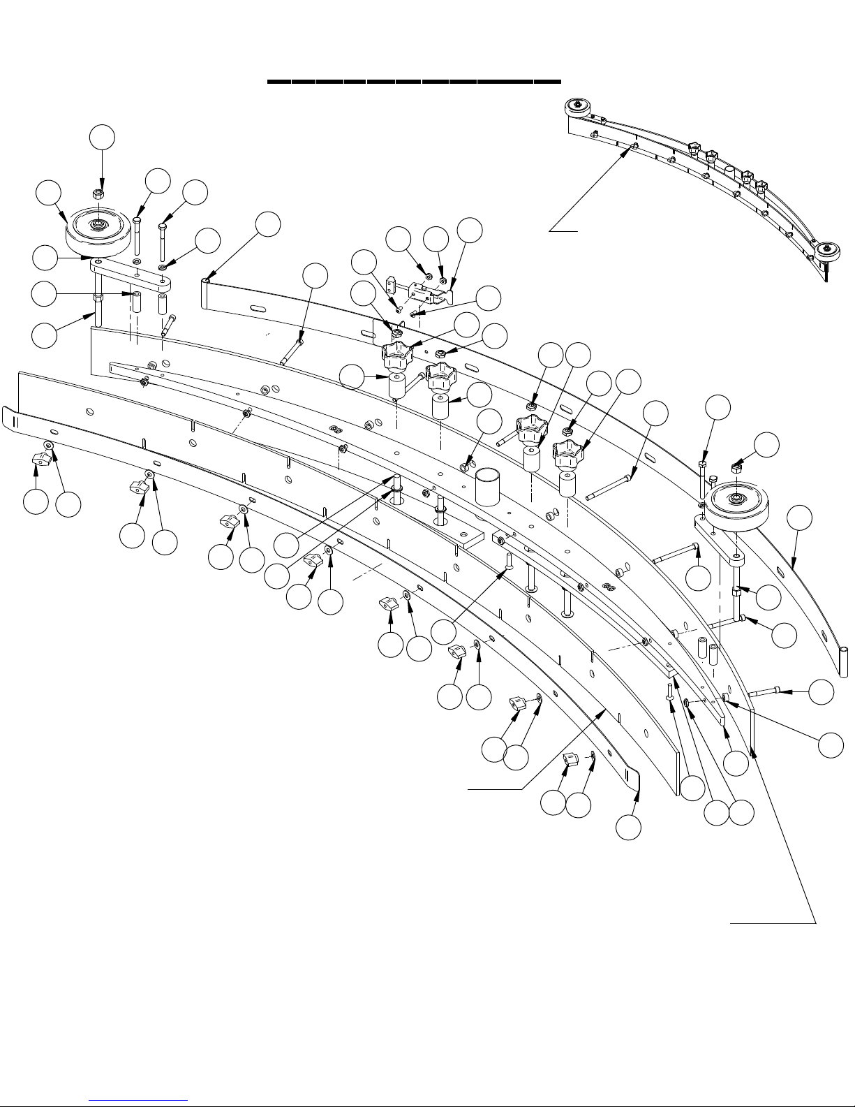
60" Squeegee
29
25
5
25
18
8
24
4
16
3
9
19
28
18
28
18
28
20
26
18
28
31 31
30
12
11
23
19
30
12
22
TO ORDER COMPLETE
60" SQUEEGEE ASSEMBLY
USE PART # 380-7180
19
12
23
12
14
25
29
10
15
9
18
370-757L LINATEX FRONT SQUEEGEE BLADE
370-757G GUM RUBBER FRONT SQUEEGEE BLADE
370-756L LINATEX REAR SQUEEGEE BLADE
370-756G GUM RUBBER REAR SQUEEGEE BLADE
27
28
18
28
18
28
18
28
13
27
16
17
22
1
21
2
PAGE 62

60" Squeegee
Item Part No. Part Description Qty.
1 370-7191 60" SQUEEGE BODY 1
2 370-7192 SQUEEGEE BODY BOTTOM (60") 2
3 H-92320 .252 ID X .50 OD X 1.25 LG SPACER 4
4 370-7183 SQUEEGE CASTER BRACKET 2
5 190-3030 4.0" WHEEL (GRAY) 2
8 370-7162 REAR SQUEEGEE BAND (RH 60") 1
9 370-7184 SQUEEGEE PIN 2
10 370-7163 REAR SQUEEGEE BAND (LH 60") 1
11 370-0124 LATCH 1
12 H-NJ06C JNYL 3/8- 16 SS 4
13 370-7171 FONT SQUEEGE BAND (60") 1
14 H-0171135 SHCS 1/4-20 X 3-1/4 SS 2
15 H-73470 SHCS 1/4-20 X 3.0 SS 2
16 H-73468 SHCS 1/4-20 X 2.5 SS 2
17 H-73465 SHCS 1/4-20 X 1.75 SS 2
18 5-418A CLAMPING KNOB 8
19 5-846 STANDOFF, 1.03" 4
20 H-0171299 BHSCS 3/8"- 16 X 3" SS 4
21 H-37020 JNYL 1/4" - 20 8
22 21-2211 SPACER 1/2 OD X 1/4" 8
23 290-5786 STAR KNOB, 3/8-16 THREAD 4
24 H-71063 LW 1/4" SS 4
25 H-77013 HCS 1/4"- 20 X 2.5" SS 4
26 H-71067 LW 3/8" SS 4
27 H-72710 FHP 1/4"- 20 X 1" SS 4
28 H-71013 FNW 1/4" X 5/8" SS 8
29 H-70862 NYLOK 3/8"-16 SS 2
30 H-73742 BHSCS 10-32 X 3/8" SS 2
31 H-0129155 JNYL #10-32, 18-8 S/S 2
PAGE 63

Squeegee trail arm and Rear axle
20
17
9
8
5
6
21
11
19
4
19
19
17
12
12
10
17
21
19
19
15
1
3
14
18
18
9
6
17
16
16
10
21
21
21
18
7
19
17
20
2
13
PAGE 64

Squeegee trail arm and Rear axle
Item Part No. Part Description Qty.
1 21-1126 ROLLER BRACKET 2
2 21-1127 ROLLER 2
3 250-1102 SCRUB DECK LIFTING BRACKET 1
4 250-2240 2" STROKE 36V ACTUATOR 450 LB LOAD 1
5 290-6186 1/2-20 X 1-1/4 " U BOLT 4
6 290-6187 LUG NUT, 1/2"- 20 8
7 370-1105 REAR BUMPER 1
8 370-6040 REAR AXLE 1
9 370-6180 14" REAR WHEEL (BLACK RUBBER) TREADED 2
10 5-122 HINGE 8" SS 2
11 H-0129159 JNYL, 1/2"-13, 18-8 SS 1
12 H-03660 .50 ID SHAFT COLLAR WITH SET SCREW 2
13 H-11319 HB 5/8"- 11 X 4" 2
14 H-13217 HCS 1/2"-13 X 3-1/2" SS 1
15 H-37038 JNYL 5/8"- 11 2
16 H-37130 NYLOK NUT, 1/2"- 20 8
17 H-70860 NYLOK 1/4"- 20 SS 17
18 H-70861 NYLOK 5/16" - 18 SS 9
19 H-74418 CB 1/4"- 20 X 5/8" S/S 8
20 H-74419 CB 1/4"- 20 X .75" SS 12
21 H-74429 CB 5/16"- 18 X 3/4" SS 9
PAGE 65

Dual vac motors
2
4
5
17
13
17
7
15
6
4
19
1
18
12
13
14
17
10
9
16
11
9
3
2
5
12
14
18
17
8
15
6
PAGE 66

Dual vac motors
Item Part No. Part Description Qty.
1 190-1450 VAC BOX 2
2 190-3002 VAC MOTOR GASKET 2
3 250-0119 1/4" ID X 9-1/2" HOSE 1
4 250-5250 36V VAC MOTOR, TANGENTAL 2
5 250-7291 EXHAUST ELBOW 2
6 290-7212 1-1/2" - 2" HOSE CUFF 2
7 370-0122 VAC MUFFLER HOSE 1
8 370-0122 VAC MUFFLER HOSE 1
9 370-4072 1-1/2" 90%DI ELBOW 2
10 390-2328 SWITCH, VACUUM SHUTOFF 1
11 390-2328A VACUUM SWITCH BARB 1
12 390-3010 LOADER VALVE 2
13 430-2502 VACUUM FAN MUFFLER 2
14 5-719 CLAMP 1 9/16 - 2 1/2 " SS 2
15 5-719 CLAMP 1 9/16 - 2 1/2 " SS 2
16 8-914 1.5" BARBED TEE 1
17 H-0427637 CLAMP 2" - 3" 4
18 H-081 CLAMP 1.0"- 1-1/8" SS 2
19 H-72515 PPH #10-32 X 1/2" S/S 1
PAGE 67

Vac motors and Solution hoses
28
34
27
31
12
12
20
11
14
18
19
1
25
8
2
24
3
16
33
29
15
24
24
24
7
24
21
6
17
36
10
5
24
32
22
26
23
31
13
30
24
4
3
35
21
PAGE 68
9

Vac motors and Solution hoses
Item Part No. Part Description Qty.
1 190-1235 ELBOW, 90 DEG X 3/8" MNPT X 3/8" BARB, NYLON 1
2 21-1601 1/2" BARBED ELBOW (PLASTIC) 1
3 290-8960 SPRAY JET HOSE 1
4 370-0001 1/2" X 12" CLEAR HOSE 1
5 370-0002 1/2" X 3" CLEAR HOSE 1
6 370-0003 1/2" X 10" CLEAR HOSE 1
7 370-0004 1/2" X 8" CLEAR HOSE 1
8 370-0005 1/2" X 16" CLEAR HOSE 1
9 370-1100 MAIN FRAME 1
10 370-4158 BALL VALVE, 3/8" 1
11 370-7245 FLOW VALVE 1
12 370-7421 TANK GASKET 2
13 390-8500 PUMP 36V DC (OPTIONAL) 1
14 4-528 CORNER SEAL STRIP 1
15 430-8910 PUMP, WATER JET, 36V 1
16 5-891B 1/2" SPRAY JET BARB 1
17 5-913 INLINE FILTER 1
18 H-00249 PPH #10-32 X 2 1/4" SS 2
19 H-02309 HCN #10-32, LG CRIMP 6
20 H-04763 .375 NPT X .5O BARB 1
21 H-04764 ELBOW, 3/8" MNPT X 1/2" BARB X 90 DEG, NYLON 2
22 H-04776 .75 NPT X .5O BARB 1
23 H-04787 .75 NPT X .75 NPT FEMALE ELBOW 1
24 H-081 CLAMP 7/16"- 25/32" SS 9
25 H-62002 HOSE CLAMP, #4 S/S 1
26 H-70003 HCS 1/4"- 20 X 3/4" SS 2
27 H-70710 HN 1/4"- 20 SS 6
28 H-70860 NYLOK 1/4"- 20 SS 6
29 H-71010 FW #10 .218 x .687 S/S 2
30 H-71013 FNW 1/4" X 5/8" SS 2
31 H-71063 LW 1/4" SS 8
32 H-72534 PPH #10-32 X 3/4" S/S 2
33 H-72536 PPH #10-32 X 1" S/S 2
34 H-74400 CB 1/4"- 20 X 6.0" SS 6
35 H-9307K74 GROMMET, 1" ID X 1-3/4" OD BUNA-N 1
36 M-5463K727 WYE, 1/2", NYLON 1
PAGE 69
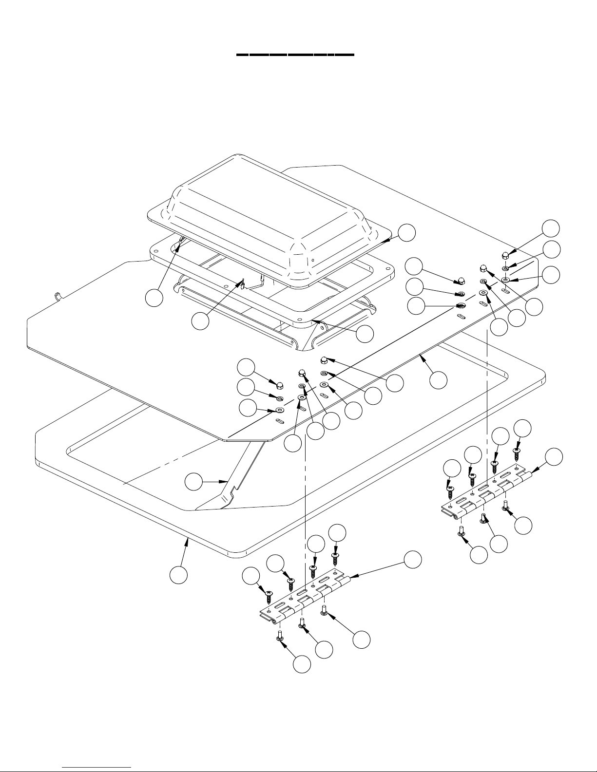
Tank Lid
3
8
10
1
1
2
8
10
9
8
10
9
4
10
9
9
10
9
8
5
11
11
11
11
8
10
9
8
7
6
11
11
PAGE 70
12
11
12
11
12
12
12
7
12

Tank Lid
Item Part No. Part Description Qty.
1 170-4060 LANYARD 2
2 190-1075 TANK CLEAR COVER GASKET 1
3 190-1410 VAC FORMED CLEAR COVER 1
4 370-1130 HOOD STAND 1
5 370-4051 TANK LID 1
6 370-7420 TANK LID GASKET 1
7 5-122 HINGE 8" SS 2
8 H-37708 1/4-20 LC ACORN NUT 6
9 H-71013 FNW 1/4" X 5/8" SS 6
10 H-71063 LW 1/4" SS 6
11 H-71894 #14 X 1" SELF TAPPING SCREW 8
12 H-74418 CB 1/4"- 20 X 5/8" S/S 6
PAGE 71

Tank Baffle
7
8
12
16
17
10
16
13
9
5
17
12
4
12
15
13
3
14
1
2
1
11
2
18
6
19
11
15
18
15
19
19
16
16
PAGE 72

Tank Baffle
Item Part No. Part Description Qty.
1 21-4028 SNAP GRIP CLAMP 1
2 21-4085 VAC SCREEN 1
3 21-7060 VAC BOX 1
4 250-8911 SCREEN STRAINER 1
5 370-0081 TANK BAND, REAR 1
6 370-0082 TANK BAND, FRONT 1
7 370-0120 1-1/2(ID) X 16" LG. TANK HOSE 1
8 370-0121 2"(ID) X 15" LG. TANK HOSE 1
9 370-1129 TANK BACK SPLASH 1
10 370-1131 RECOVERY TANK BAFFEL 1
11 370-1133 TANK BRACE 2
12 H-01201 GROMMET 4
13 H-0129154 JAM NYLOK #10-24 SS 3
14 H-70858 NYLOK #10-32 SS 2
15 H-70860 NYLOK 1/4"- 20 SS 3
16 H-71894 #14 X 1" SELF TAPPING SCREW 4
17 H-72536 PPH #10-32 X 1" S/S 2
18 H-72704 FHP 1/4"- 20 X 1/2" SS 3
19 H-74419 CB 1/4"- 20 X .75" SS 3
PAGE 73

Solution/recovery Tank
RED TANK USE PART # 370-4040
GRANITE TANK USE PART # 370-4041
4
2
7
6
18
19
13
22
24
15
23
14
2
25
16
3
24
13
19
19
24
9
1
10
12
1
11
17
7
5
8
21
20
PAGE 74

Solution/recovery Tank
Item Part No. Part Description Qty.
1 190-1210 2.0 NPT X 2.0" BARB 2
2 190-1215 2.0 NPT X 1.50 BARB 2
3 21-4044 3/4" NPT TO 3/4" BARBED ELBOW 1
4 290-7040 2" NPT X 2" BARB ELBOW, BLACK 2
5 370-0111 SQUEEGEE HOSE 1
6 370-0112 TANK TO VAC HOSE 1
7 370-1210 2" NPT TANK PLUG 2
8 370-1370 SIGHT TUBE 1
9 370-7180 TANK UTILITY HANDLE 1
10 370-7185 STROBE LIGHT BRACKET 1
11 370-7209 2" DRAIN HOSE 1
12 370-7210 RECOVERY DRAIN HOSE 1
13 4-124 LATCH 2
14 5-720 DRAIN HOSE END TUBE 1
15 5-727 DRAIN HOSE PLUG 1
16 5-886 WAND CLIP 1
17 5-887 VAC WAND 1
18 8-293 STROBE LIGHT 1
19 H- FHP #8-32 X 3/8" SS 4
20 H-04788 .50 NPT X .5O BARB 1
21 H-04789 1.0 NPT X 1.0 BARB 1
22 H-2S444 SB 5/16" X 3/8" SS 1
23 H-70856 NYLOK #8-32 SS 4
24 H-71894 #14 X 1" SELF TAPPING SCREW 4
25 H-NJ05C JNYL 5/16"- 18 SS 1
PAGE 75

Tank Mounting
6
5
3
4
3
5
8
9
7
10
10
10
1
11
10
2
8
9
7
10
PAGE 76

Tank Mounting
Item Part No. Part Description Qty.
1 290-8960 SPRAY JET HOSE 1
2 370-1100 MAIN FRAME 1
3 370-7421 TANK GASKET 2
4 370-7422 TANK GASKET 2
5 5-122 HINGE 8" SS 2
6 5-895 SPRAY NOZZLE 1
7 H-70003 HCS 1/4"- 20 X 3/4" SS 5
8 H-71013 FNW 1/4" X 5/8" SS 5
9 H-71063 LW 1/4" SS 5
10 H-74418 CB 1/4"- 20 X 5/8" S/S 8
11 H-9307K74 GROMMET, 1" ID X 1-3/4" OD BUNA-N 1
PAGE 77

Standard Batteries and Seat
28
31
15
21
32
31
38
17
18
29
29
24
17
12
4 38
40
7
18
18
19
26
39
31
30
30
29
11
37
RED BATTERY COMPARTMENT LID
USE PART # 370-1102
GRANITE BATTERY COMPARTMENT LID
USE PART # 370-1101
RED BATTERY COMPARTMENT
USE PART # 370-1103
17
38
GRANITE BATTERY COMPARTMENT
USE PART # 370-1104
17
38
38
13
14
35
16
28
28
36
22
29
5
20
33
18
20
29
2
TO ORDER BATTERY
WIRING HARNESS USE
PART # 370-1900
29
10
38
8
35
28
35
3
29
28
27
38
23
34
27
25
6
38
34
9
38
PAGE 78

Standard Batteries and Seat
Item Part No. Part Description Qty.
1 21-2230 MICRO SWITCH 1
2 290-2110 L 16 H BATTERY 6 VOLT 395 AH 6
3 370-0000 370 BATTERY BOX 1
4 370-0014 CUP HOLDER 1
5 370-0112 TANK TO VAC HOSE 1
6 370-1100 MAIN FRAME 1
7 370-1108 (2) QUART TRAY 1
8 370-1201 SEAT SUPPORT 1
9 370-2441 ON BOARD CHARGER 1
10 370-7040 TANK CABLE 2
11 390-2576 350 GREY CONNECTOR WITH 1/0 CONTACTS 1
12 430-1225 13" SS HINGE 1
13 5-100 GROMMET 1
14 5-130 DOOR LATCH 1
15 8-143 SEAT WITH ARM RESTS 1
16 8-180 HINGE, 6-7/8" S/S 1
17 H-01201 GROMMET 4
18 H-0129154 JAM NYLOK #10-24 SS 4
19 H-083 BOLT HEAD CAP 1
20 H-33080 FW 5/16" SS 8
21 H-37708 1/4-20 LC ACORN NUT 5
22 H-40031 BATTERY BOOT 12
23 H-400317 TERMINAL COVER 12
24 H-70002 HCS 1/4"-20 X 1/2 SS" 6
25 H-70055 HCS 5/16"- 18 X 1" SS 4
26 H-70710 HN 1/4"- 20 SS 1
27 H-70858 NYLOK #10-32 SS 6
28 H-70860 NYLOK 1/4"- 20 SS 11
29 H-70861 NYLOK 5/16" - 18 SS 16
30 H-70925 KN 1/4-20 S/S 2
31 H-71013 FNW 1/4" X 5/8" SS 7
32 H-71063 LW 1/4" SS 5
33 H-71065 LW 5/16" SS 4
34 H-72685 FHP 10-32 X 1" SS 3
35 H-74417 CB 1/4"- 20 X .5" SS 4
36 H-74418 CB 1/4"- 20 X 5/8" S/S 5
37 H-74422 CB 1/4"- 20 X 1-1/2" SS 2
38 H-74429 CB 5/16"- 18 X 3/4" SS 10
39 H-77009 HCS 1/4"- 20 X 1.5" SS 1
40 H-87712 FELT TABS 2
PAGE 79

Industrial Battery and Seat
14
20
19
8
16
24
10
17
10
21
26
23
9
RED BATTERY BOX LID (HD)
USE PART # 370-1302
GRANITE BATTERY BOX LID (HD)
USE PART # 370-1301
17
RED BATTERY BOX (HD)
PART # 370-1203
GRANITE BATTERY BOX (HD)
26
PART # 370-1204
23
21
24
12
3
11
10
22
18
11
26
13
7
1
17
12
6
17
5
16
25
2
13
10
11
26
1
4
26
17
15
21
13
PAGE 80

Industrial Battery and Seat
Item Part No. Part Description Qty.
1 253-1040 TANK STRAP SUPPORT 2
2 370-1040 BATTERY COMPARTMENT STRAP (HD) 1
3 370-1100 MAIN FRAME 1
4 370-1202 SEAT SUPPORT (HD) 1
5 370-1205 INDUSTRIAL BATTERY BRACKET 1
6 370-2110 INDUSTRIAL BATTERY 1
7 390-2576 350 GREY CONNECTOR WITH 1/0 CONTACTS 1
8 430-1225 13" SS HINGE 1
9 8-143 SEAT WITH ARM RESTS 1
10 H-01201 GROMMET 6
11 H-0129154 JAM NYLOK #10-24 SS 6
12 H-312HCN HCN 5/16"-18 2
13 H-33080 FW 5/16" SS 12
14 H-37708 1/4-20 LC ACORN NUT 5
15 H-70055 HCS 5/16"- 18 X 1" SS 6
16 H-70860 NYLOK 1/4"- 20 SS 8
17 H-70861 NYLOK 5/16" - 18 SS 14
18 H-70925 KN 1/4-20 S/S 2
19 H-71013 FNW 1/4" X 5/8" SS 5
20 H-71063 LW 1/4" SS 5
21 H-71065 LW 5/16" SS 8
22 H-73753 BHSCS 1/4 - 20 X 5/8" SS 2
23 H-73780 BHSCS 5/16-18 X 1 2
24 H-74418 CB 1/4"- 20 X 5/8" S/S 11
25 H-74421 CB 1/4"- 20 X 1-1/4" SS 2
26 H-74429 CB 5/16"- 18 X 3/4" SS 8
PAGE 81

Central Command
333130
21
6
5
32
17
17
17
18
36
38
13
34
15
36
38
3
7
16
23
36
19
38
40
35
22
4
14
15
2
11
20
40
40
26
20
27
RED CONTROL BOX
USE PART # 370-2010
GRANITE CONTROL BOX
USE PART # 370-2011
9
20
9
25
20
42
41
9
1
43
36
38
37
40
39
37
40
24
8
10
28
29
12
12
40
40
44
37
40
41
RED CONTROL BOX DOOR
USE PART # 370-2001
GRANITE CONTROL BOX DOOR
USE PART# 275-2001
42
39
40
PAGE 82

Central Command
Item Part No. Part Description Qty.
1 290-2004 ACCESS COVER GASKET 1
2 290-2015 ONE TOUCH BUTTON 1
3 290-2300 LOW SOLUTION (AMBER) 1
4 290-2310 FULL RECOVERY (RED) 1
5 290-234 KEY SWITCH 1
6 290-234A KEY SET (REPLACE) 1
7 290-2891 LCD SCREEN 1
8 290-2899 COMPUTER CONTROL V3 1
9 290-8370 FUSE, RESETTABLE, 50 AMP, 50V DC MAX 3
10 370-2006 HARDWARE PANEL 1
11 370-2013 CONTROL PANEL TOP PLATE 1
12 370-2331 RELAY, 36V, SMALL W/FLAT MTG PLATE 2
13 390-1501 Central Command Decal 1
14 5-233 MOM-OFF-MOM DPDT 1
15 5-234 SWITCH, ROCKER, DPDT, ON/ON 2
16 5-296 DIODE BRIDGE 1
17 5-300 EMERGENCY SHUT OFF 1
18 5-301 EMERGENCY LEGEND PLATE 1
19 5-302 EMERGENCY CONTACT BLACK 1
20 5-892 TOGGLE, ON-OFF SPST 5
21 5-892A PROTECTIVE BOOT, TOGGLE SWITCH, (GRAY) 1
22 7-229 PUSH BUTTON SWITCH 1
23 7-283 SWITCH, TOGGLE, MOM/OFF/MOM (DPDT) 1
24 7-287 BUSS BAR UHMW 2
25 7-821 SWITCH, TOGGLE, ON/ON (DPDT) 1
26 7-837 FUSE RESETTABLE 2 AMP 1
27 8-180 HINGE, 6-7/8" S/S 1
28 8-294 HORN 1
29 E-5HBB 5 HOLE BUSS BAR 2
30 H-01195 PROTECTIVE BOOT, TOGGLE SWITCH, (WHITE) 1
31 H-01196 PROTECTIVE BOOT, TOGGLE SWITCH, (RED) 1
32 H-01197 PROTECTIVE BOOT, TOGGLE SWITCH, (YELLOW) 1
33 H-01198 PROTECTIVE BOOT, TOGGLE SWITCH, (GREEN) 1
34 H-01199 PROTECTIVE BOOT, TOGGLE SWITCH, (BLUE) 1
35 H-01200 PROTECTIVE BOOT, TOGGLE SWITCH, (BLACK) 1
36 H-13005 HCS 1/4"-20 X 1" 4
37 H-250HCN HCN 1/4"-20 8
38 H-33078 FW 1/4" SAE 4
39 H-33618 LW 1/4" 4
40 H-36102 HN 1/4"-20 12
41 H-71013 FNW 1/4" X 5/8" SS 4
42 H-73754 BHSCS 1/4 - 20 X 3/4" SS 4
43 H-74417 CB 1/4"- 20 X .5" SS 5
44 H-9307K74 GROMMET, 1" ID X 1-3/4" OD BUNA-N 3
PAGE 83

Steering Tower
25
27
24
RED COVER USE
PART # 290-1172
GRANITE COVER USE
PART # 292-1172
24
15
26
27
20
15
1
25
13
6
28
20
3
7
RED UPPER STEERING TOWER
USE PART # 290-1171
GRANITE UPPER STEERING TOWER
USE PART # 292-1171
2
21
9
16
21
28
1
3
20
8
5
17
18
19
10
14
20
15
26
15
4
23
23
22
16
15
11
8
15
12
RED LOWER STEERING TOWER
USE PART # 290-1170
GRANITE LOWER STEERING TOWER
USE PART # 292-1170
PAGE 84

Steering Tower
Item Part Number Part Description Qty
1 290-1245 3/8" ID, 1/2" OD, 3/8" LG, FLANGE BEARING 2
2 290-1247 BRONZE THRUST BEARING, .50" ID X 1.0" OD X 1/16" TH 2
3 290-1248 FW BRONZE 1/2" ID X 1" OD X 1/8" TH 2
4 290-7050 INDEX PLUNGER 1
5 4-101 SERIAL NUMBER PLATE 1
6 4-352 BEARING 1
7 4-364A FLANGE, 1.75" ID 2
8 430-2910 36V HEADLIGHT 2
9 430-2940 36V HORN 1
10 5-892 TOGGLE, ON-OFF SPST 1
11 8-262 HOUR METER 1
12 8-292 BACKUP ALARM 1
13 8-294B PUSH BUTTON SWITCH, SILVER 1
14 H-01200 PROTECTIVE BOOT, TOGGLE SWITCH, (BLACK) 1
15 H-250HCN HCN 1/4"-20 12
16 H-36104 HN 5/16"-18 4
17 H-41009 AB4-3A BLIND RIVET 4
18 H-70858 NYLOK #10-32 SS 2
19 H-71009 FW #10 SS 2
20 H-71017 FW 3/8" X 7/8" SS 4
21 H-71065 LW 5/16" SS 4
22 H-72515 RPH #10-32 X 1/2" SS 2
23 H-72681 FHP #10-32 X 3/8" SS 2
24 H-73754 BHSCS 1/4 - 20 X 3/4" SS 6
25 H-73780 BHSCS 5/16-18 X 1 4
26 H-73815 BHSCS 3/8"- 16 X 1" SS 2
27 H-76061 FW 1/4" NYLON 6
28 H-NJ06C JNYL 3/8- 16 SS 2
PAGE 85
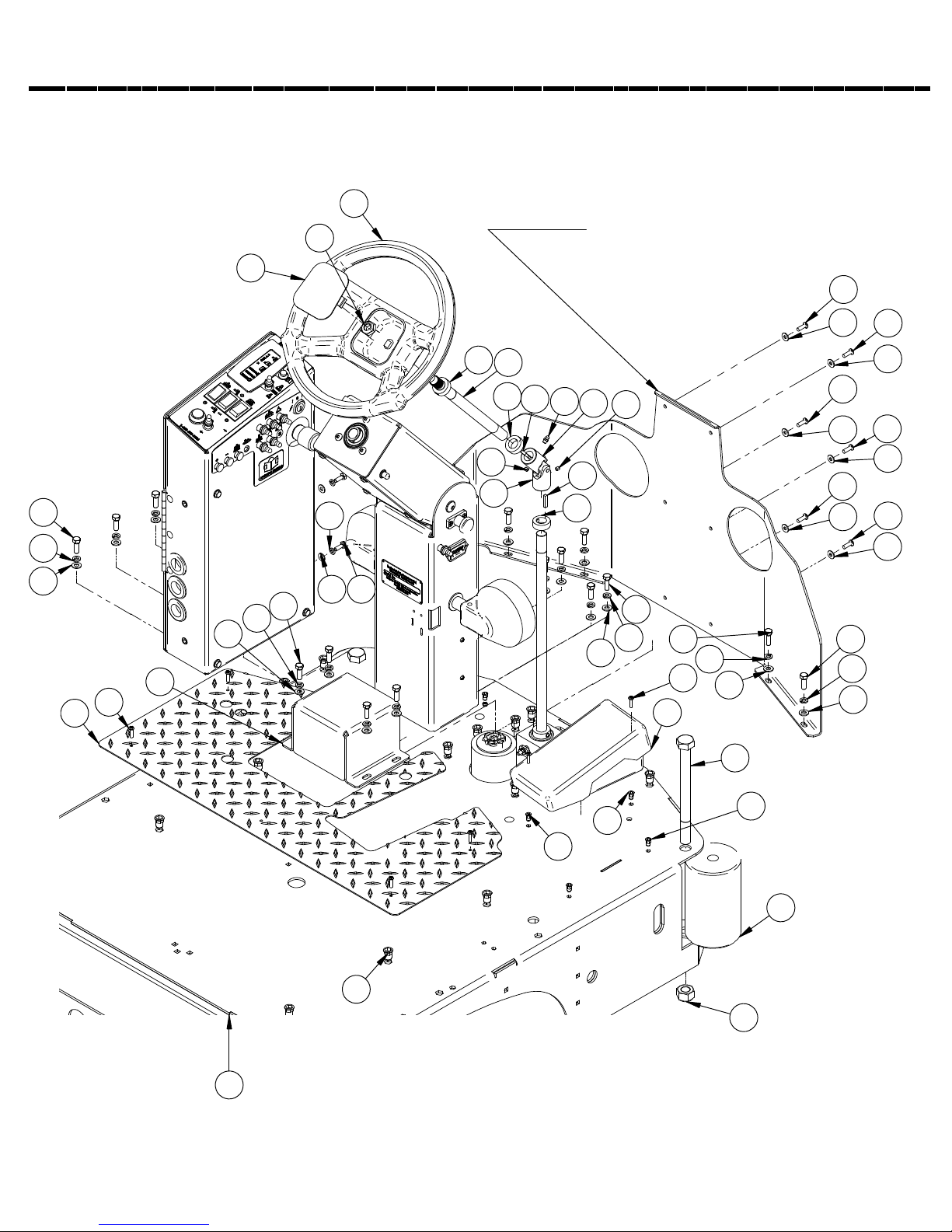
Central Command and Steering Tower
10
18
9
RED FRONT APRON
USE PART # 370-1180
GRANITE FRONT APRON
USE PART # 370-1181
26
27
26
21
24
16
26
27
26
27
21
24
27
26
27
26
27
16
17
2
17
11
4
3
14
14
3
23
22 20
21
24
16
1
25
6
12
17
11
16
12
21
24
8
21
25
24
16
13
12
5
7
15
19
PAGE 86

Central Command and Steering Tower
Item Part No. Part Description Qty.
1 250-1173 DRIVE COVER 1
2 290-7090 STEERING SHAFT, UPPER 1
3 290-7110 U-JOINT 1
4 290-7111 1/4-28 ZERK FITTING 1
5 370-1100 MAIN FRAME 1
6 370-1610 NON SKID FLOOR PLATE 1
7 7-125A ROLLER 2
8 8-290 FOOT PEDAL 1
9 8-701A STEERING COVER 1
10 8-703 STEERING WHEEL 1
11 H-01125 3/16" X 1" KEY 2
12 H-02309 HCN #10-32, LG CRIMP 14
13 H-11380 HCS 3/4-10 X 8-1/2 2
14 H-25379 SETSCREW, KCP, 1/4"-20 X 1/4" 3
15 H-312HCN HCN 5/16"-18 20
16 H-33080 FW 5/16" SS 15
17 H-33376 .75 ID SHAFT COLLAR WITH SET SCREW 3
18 H-37038 JNYL 5/8"- 11 1
19 H-37039 NYLOK 3/4"- 10 2
20 H-70003 HCS 1/4"- 20 X 3/4" SS 2
21 H-70055 HCS 5/16"- 18 X 1" SS 15
22 H-71013 FNW 1/4" X 5/8" SS 2
23 H-71063 LW 1/4" SS 2
24 H-71065 LW 5/16" SS 15
25 H-72534 PPH #10-32 X 3/4" S/S 8
26 H-73754 BHSCS 1/4 - 20 X 3/4" SS 6
27 H-76061 FW 1/4" NYLON 6
PAGE 87

Side doors
1
4
4
4
4
3
3
3
3
2
40" LEFT HAND DOOR
USE PART # 370-9597
40" RIGHT HAND DOOR
USE PART # 370-9596
46" LEFT HAND DOOR
USE PART # 370-9599
46" RIGHT HAND DOOR
USE PART # 370-9598
Item Part No. Part Description Qty.
1 5-122 8" SS HINGE 1
2 5-130 DOOR LATCH 1
3 H-70860 NYLOK 1/4"- 20 SS 4
4 H-74417 CB 1/4"- 20 X .5" SS 4
PAGE 88

Side doors
2
1
Item Part No. Part Description Qty.
1 370-1100 MAIN FRAME 1
2 H-70003 HCS 1/4"- 20 X 3/4" SS 4
3 H-70860 NYLOK 1/4"- 20 SS 4
PAGE 89
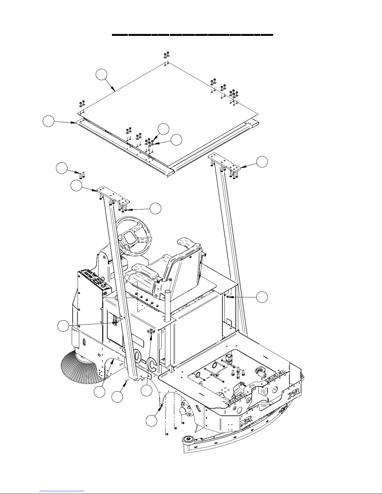
Overhead Guard
5
4
7
8
3
9
2
10
12
6
1
11
13
6
PAGE 90

Overhead Guard
Item Part No. Part Description Qty.
1 370-1100 MAIN FRAME 1
2 370-1701 OVERHEAD GUARD SUPPORT (LH) 1
3 370-1702 OVERHEAD GUARD SUPPORT (RH) 1
4 370-1703 ROOF SUPPORT 1
5 370-1704 OVERHEAD GUARD ROOF 1
6 H-70861 NYLOK 5/16" - 18 SS 12
7 H-70862 NYLOK 3/8"-16 SS 20
8 H-71017 FW 3/8" X 7/8" SS 20
9 H-74415 CB 3/8"- 16 X 1-3/4" SS 4
10 H-74416 CB 3/8"- 16 X 2-1/4" SS 16
11 H-74430 CB 5/16"- 18 X 1" SS 8
12 H-74463 CB 5/16"- 18 X 2-1/4" SS 4
13 H-98025 FW 3/8" GRADE 8 8
PAGE 91

Water jet kit
6
1
10
2
3
7
5
4
8
Item Part No. Part Description Qty.
1 21-1601 1/2" BARBED ELBOW (PLASTIC) 1
2 290-8960 SPRAY JET HOSE 1
3 370-0003 1/2" X 10" CLEAR HOSE 1
4 430-8910 PUMP, WATER JET, 36V 1
5 5-891B 1/2" SPRAY JET BARB 1
6 5-895 SPRAY NOZZLE 1
7 H-081 CLAMP 7/16"- 25/32" SS 2
8 H-71010 FW #10 .218 x .687 S/S 1
9 H-72536 PPH #10-32 X 1" S/S 2
10 H-9307K74 GROMMET, 1" ID X 1-3/4" OD BUNA-N 1
9
PAGE 92

Vac wand kit
1
2
Item Part No. Part Description Qty.
1 5-883 SQUEEGEE HOSE 1
2 5-887 VAC WAND 1
3 5-889 VACUUM NOZZLE 1
4 7-884 COUPLER, S/S 1
P/N 21-11
COMPLETE ASSEMBLY
PAGE 93
4
3
 Loading...