

Page 1
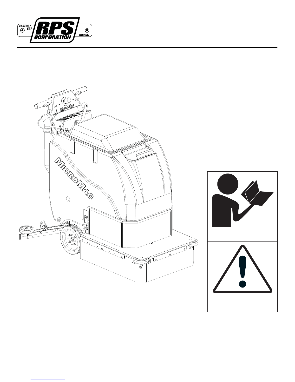
MICROMAG
Operating Instructions (EN)
MODELS:
17'' DISK PAD ASSIST
20'' DISK PAD ASSIST
17'' DISK TRACTION
20'' DISK TRACTION
20'' EDGE TRACTION
Read these Instructions before
using the machine.
Read these Safety Messages
before using the machine.
www.rpscorporation.com
www.factorycat.com VERSION 14.0117
www.tomcatequip.com MICROMAG-OP-EN
© 2014 RPS Corporation
Page 2
INTRODUCTION
This manual is furnished with each new machine. This manual will allow the Operator to get the best performance out of
your RPS manufactured Scrubber-Drier, Sweeper, Burnisher, or Orbital Scrubber. Read this manual thoroughly before
operating or servicing the machine.
This machine will provide excellent performance, but the best results will be obtained at the most minimum costs if:
• The machine is regularly maintained - per the machine Preventative Maintenance instructions provided.
• The machine is operated with reasonable care and caution.
• The machine is maintained with manufacturer supplied parts.
ABOUT THIS MANUAL
TABLE OF CONTENTS: Tells you where to look in the manual.
SAFETY MESSAGES: Section contains important information regarding hazard or unsafe practices of the machine. Lev-
els of hazards are identifi ed that could result in product or personal injury, or severe injury resulting in death.
OPERATION CONTROLS / MACHINE COMPONENTS: Shows you the different machine controls and features.
MACHINE SETUP: Tells you how to setup machine from un-crating to installing Squeegee and Brushes.
MACHINE OPERATION: Section is to familiarize the operator with the operation and function of the machine.
BATTERY CHARGING: Shows you how to charge the Batteries (on-board and off board charging).
MAINTENANCE: This section contains preventative maintenance to keep the machine and it’s components in good work-
ing condition. They are listed in this general order:
• Batteries
• Scrub Brushes
• Adjusting Squeegee
• Service Schedule
• Machine Trouble Shooting
TROUBLE SHOOTING: A list of common problems that may occur.
MACHINE SPECS: Tells you Machine Specifi cations for the various parts of the machine.
MACHINE INSTALL FORM: Should be fi lled out upon machine installation and faxed to 1-866-632-6961 or on-line at
www.rpscorporation.com.
WARRANTY POLICY: Tells you coverage, exclusions and limitations to Warranty.
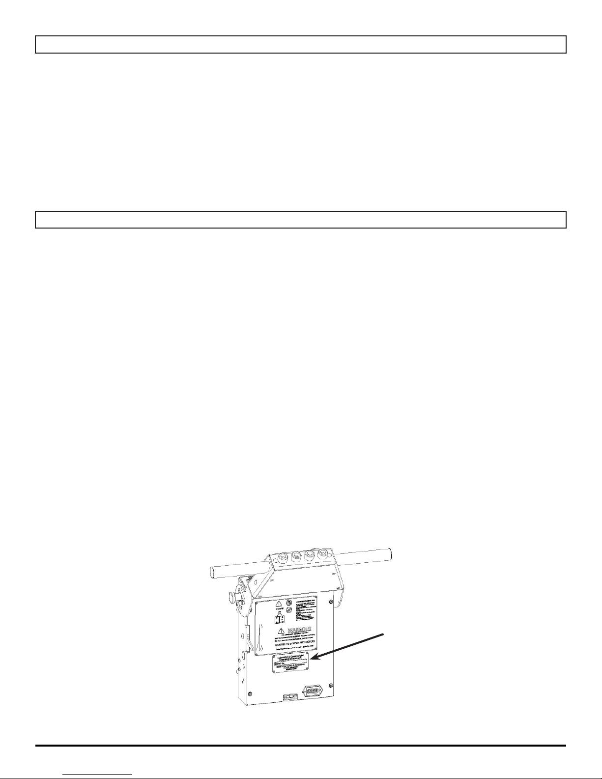
NOTE: The Serial Number of your machine is located on the lower half of the Control Panel of the machine.
AS OUR POLICY IS ONE OF CONSTANT IMPROVEMENT - ALL INFORMATION AND
SPECIFICATIONS ARE SUBJECT TO CHANGE WITHOUT NOTICE.
- 2 - MICROMAG-OP-EN
SERIAL NUMBER
Page 3

TABLE OF CONTENTS
Introduction 2
About This Manual 2
Table of Contents 3
Safety Messages 4
Safety Label Locations 6
Operation Controls 7
Machine Components 8
Machine Components 9
Machine Setup 10
Un-Crating Machine: 10
Connecting Batteries: 10
Attaching Squeegee: 10
Adjusting Squeegee: 11
Removing Squeegee: 11
Replacing or Rotating Squeegee Blades: 11
Installing Disk Pad Driver or Brush: 12
Installing Driver Pads: 12
Replacing Driver Pads on Machine: 12
Installing EDGE Pads: 13
Adjusting Pad Assist Bias: 13
Machine Operation 14
Pre-Cleaning Checklist: 14
Operating Hints: 14
One Pass Scrubbing (Pad Assist): 15
Scrub Only: 15
Vacuum Only: 15
One Pass Scrubbing (Traction): 16
Scrub Only: 16
Vacuum Only:
Adjust Solution Flow:
Draining Solution Tank: 17
Draining Recovery Tank: 17
Open Recovery Lid: 17
Flush Recovery Tank: 18
Clean “Drain Saver”: 18
Clean Vacuum Screen: 18
16
17
Tip Tank: 19
Squeegee Up: 19
Squeegee Down:
Vacuum Motor: 20
Solution Filter: 20
Cleaning Solution Filter: 20
19
Battery Charging 21
External Battery Charging: 21
On-Board Charger 22
On-Board Battery Charging (Optional): 22
Battery Maintenance Guide 23
Safety: 23
Inspection and Cleaning: 23
Storage: 23
Maintenance 24
Daily Maintenance: 24
Weekly Maintenance: 24
Monthly Maintenance: 24
Yearly Maintenance: 24
Storing Machine: 24
Checking Battery Specifi c Gravity: 24
PM Records 25
Trouble-shooting 27
Machine Specs 29
Common Wear Parts 30
Round Disk Brushes: 30
Round Disk Pads: 30
EDGE Pads and Screens: 30
Squeegee Blade Kits & Assemblies: 31
Soap Choices 32
Standard Warranty Policy 34
Machine Install / Warranty Registration 35
MICROMAG-OP-EN - 3 -
Page 4
SAFETY MESSAGES
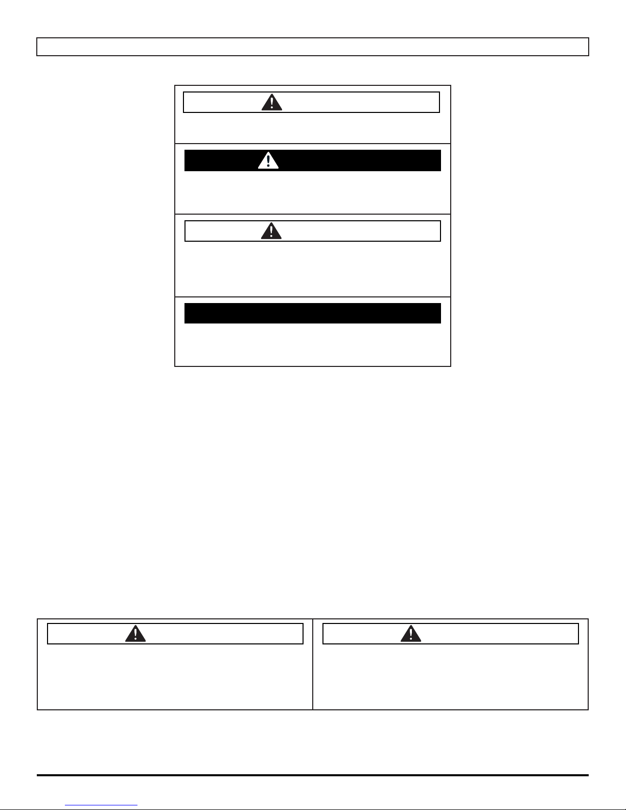
You will see four kinds of safety reminders in this manual:
DANGER
DANGER indicates a hazardous situation which, if not
avoided, will result in death or serious injury.
WARNING
WARNING indicates a potentially hazardous situation
which, if not avoided, could result in death or serious
injury.
CAUTION
CAUTION indicates a potentially hazardous situation
which, if not avoided, could result in minor or moderate
injury or damage to this machine or nearby objects. CAUTION also can be used to alert against unsafe practices.
NOTICE
NOTICE indicates information considered important, but
not hazard-related. This safety message may be related
to property damage or warranty warnings.
Your safety, and that of others, is very important. Operating this machine safely is an important responsibility.
DO NOT OPERATE THIS MACHINE UNLESS:
• You are trained and authorized to do so
• You have read and understood this Operator’s Manual
• On surfaces with greater than a 2% grade unless this machine is equipped with a functional Parking Brake.
WHEN OPERATING THIS MACHINE:
• Remove loose objects from the fl oor that could be projected from the rotating Brushes
• Keep your hands and feet away from the rotating Brushes
• Do not operate this machine where fl ammable liquids are present
• Use caution when maneuvering
BEFORE LEAVING THE MACHINE:
• Park the machine on a level surface
• Turn the machine off
BEFORE SERVICING THE MACHINE:
• Disconnect the Batteries
DANGER
Explosive hydrogen gas forms when Batteries are
charging. An open fl ame or spark can cause this gas
to explode. Serious personal injury or property damage
could occur. Only charge the Batteries in this machine in
a well ventilated area.
Flammable materials can cause an explosion or fi re. Do
not use fl ammable materials in Tank or pick up.
DANGER
- 4 - MICROMAG-OP-EN
Page 5
WARNING
The Batteries in this machine produce hazardous
voltage which can cause electrical shock, burns and/
or electrocution. Always disconnect batteries before
servicing this machine.
WARNING
When climbing or descending ramps, always drive
machine forward. To avoid overturning the machine, Do
not back down ramps. Do not drive across inclines. Do
not turn while ascending or descending ramps. Overturning the machine can cause serious injury or death.
WARNING
Do not use water that exceeds 135°F / 57°C. If wa-
ter is above said temperature, this will void the Tank
Warranty.
WARNING
Do not park this machine on ramps or slopes. Always
park this machine on a level, hard surface. Do not operate this machine outdoors or on uneven surfaces.
WARNING
The Batteries in this machine contain sulfuric acid,
which causes burns to skin. If battery acid contacts
clothing or skin, rinse the effected area with cold water
immediately. If battery acid gets on your face or in your
eyes, fl ush the area immediately with cold water and
seek medical attention.
WARNING
Dress safely. Do not wear rings or metal wrist watches
when servicing this machine, as they can cause an
electrical short circuit which can cause serious burns.
WARNING
Do not remove, paint over or destroy warning decals. If
warning decals become damaged, call 1-262-681-3583
for free replacements.
WARNING
Dress safely. Do not wear a neck tie, scarf, or any
loose or dangling clothing while operating this machine.
Loose or dangling clothing or neck-wear can tangle in
rotating parts, causing serious injury or death.
WARNING
Always turn off this machine before leaving it unattended. Do not allow untrained persons to operate this
machine.
WARNING
NO RIDERS. Do not carry passengers on this machine. Do not use this machine as a stepladder or work
platform.
WARNING
Understand the dynamic braking system before you
operate the machine on ramps. Machine may coast.
WARNING
To avoid electrical shock, do not operate this machine
over electrical fl oor outlets.
CAUTION
To avoid damage to this machine, use only cleaning
solutions and replacement parts recommended by the
manufacturer.
CAUTION
Do not operate this machine if any parts have been
damaged or removed.
WARNING
Before you service a Battery, always wear face protection, protective gloves and protective clothing. Battery
acid or Battery explosion can cause serious injuries.
CAUTION
Always use the automatic battery charger provided by
the manufacturer of this machine to charge the Batteries of this machine. It is designed to charge the Batteries at the appropriate rate. If you must use a different
charger, disconnect the Batteries before charging to
avoid damage to the electronic speed controller.
CAUTION
To avoid damage to the electronic control components
of this machine, Do not store this machine outdoors. Do
not pressure wash this machine.
MICROMAG-OP-EN - 5 -
Page 6
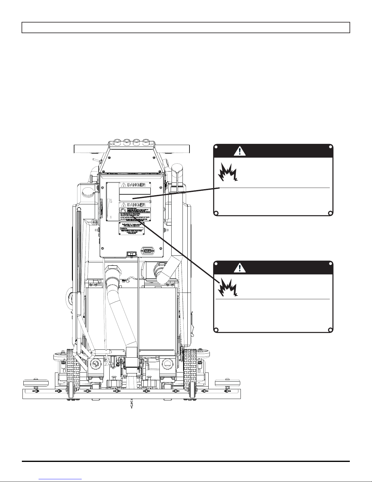
SAFETY LABEL LOCATIONS
Read and obey all Safety Labels on your MICROMAG Floor Scrubber. If you have questions about these labels, ask your
supervisor.
These images indicate where on the MICROMAG Safety Labels are located. If ever the labels become illegible, worn off, or
torn, promptly report it to your supervisor and replace it.
DANGER
EXPLOSIVE HYDROGEN GAS FORMS WHEN
BATTERIES ARE CHARGING. AN OPEN FLAME
OR SPARK CAN CAUSE THIS GAS TO EXPLODE.
ONLY CHARGE THE BATTERIES IN THIS MACHINE IN A WELL VENTILATED AREA.
USE ONLY DISTILLED WATER IN THE BATTERIES. USE
ONLY THE OEM CHARGER PROVIDED WITH THE MACHINE. ALWAYS DISCONNECT THE BATTERY BEFORE
SERVICING THE MACHINE.
REFER TO MANUAL OR CALL +011-262-681-3583
BATTERY CHARGING LABEL
EXPLOSION RISK!
PART #: 253-7280
DANGER
EXPLOSION RISK!
&,!--!",%-!4%2)!,3#!.#!53%!.
%80,/3)/./2&)2%$/./453%&,!-
-!",%-!4%2)!,3).4!.+/20)#+50
TO AVOID DAMAGE TO THIS MACHINE:
s53%!002/6%$$%4%2'%.43/.,9
s7!4%24%-0%2!452%-534./4%8#%%$˚F/ 54˚#
s$/./453%()'(0%2#%.4!'%",%!#(-)8452%
REFER TO MANUAL OR CALL +011-262-681-3583
TANK LABEL
PART #: 5-728
- 6 - MICROMAG-OP-EN
Page 7
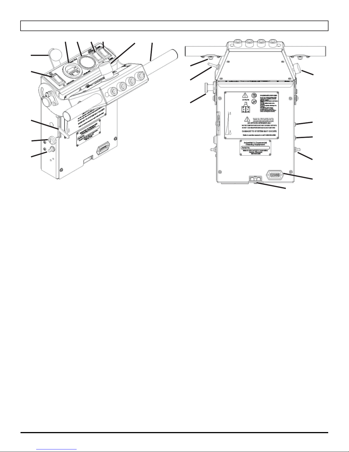
OPERATION CONTROLS
67 8 9
5
4
3
2
1
1. MAIN POWER SWITCH (OPTIONAL): Turns the machine ON and OFF
2. KEY SWITCH: Turns power on to the machine (Standard on Traction Drive, Optional
on Pad Assist Drive)
3. SOLUTION CONTROL LEVEL: Controls solution fl ow (Up = LESS, Down = MORE)
4. VACUUM SWITCH: Turns the Squeegee Vacuum Motor ON and OFF
5. SQUEEGEE LIFT LEVER: Raises and lowers the Squeegee
6. BATTERY GAUGE / HOUR METER: Indicates the amount of Battery charge
remaining
7. SCRUBDECK DOWN PRESSURE GAUGE (OPTIONAL): Shows the amount of
down pressure applied to Scrubdeck
8. SCRUBDECK SWITCH: Turns the Scrubdeck ON or OFF and UP or DOWN
9. SOLUTION FLOW SWITCH: Turns Solution Flow ON or OFF
10. EMERGENCY SHUT OFF SWITCH (OPTIONAL): Shuts OFF the machine in case
of emergency
11. HANDLE BAR: Adjustable Handlebar
12. ADJUSTABLE HANDLE BAR LOCK: Pull out to adjust Handlebar and release to
lock the Handlebar in place
13. REVERSE SWITCH: Pull back for reverse
14. DRIVE BUTTON: Press to drive forward, release to stop
15. SPEED CONTROL KNOB: Controls the speed of the Traction Drive - Turn counter-
clockwise to reduce speed
16. CIRCUIT BREAKER: 25 AMP resettable circuit breaker for Vacuum Motor
17. CIRCUIT BREAKER: 30 AMP resettable circuit breaker for Scrubdeck Motor (40
AMP for HD 1.2 HP motor option)
18. SPRAY JET [BLUE BOOT] (OPTIONAL): Activates Spray Pump for remote Spray
Wand
19. RECHARGE CYCLE METER: Shows the amount of chargers on a machine
20. CHARGER PORT: Red 50 used to receive charger input for optional external
charger - 24V ONLY!
10 11
14
15
13
12
16
17
18
19
20
MICROMAG-OP-EN - 7 -
Page 8
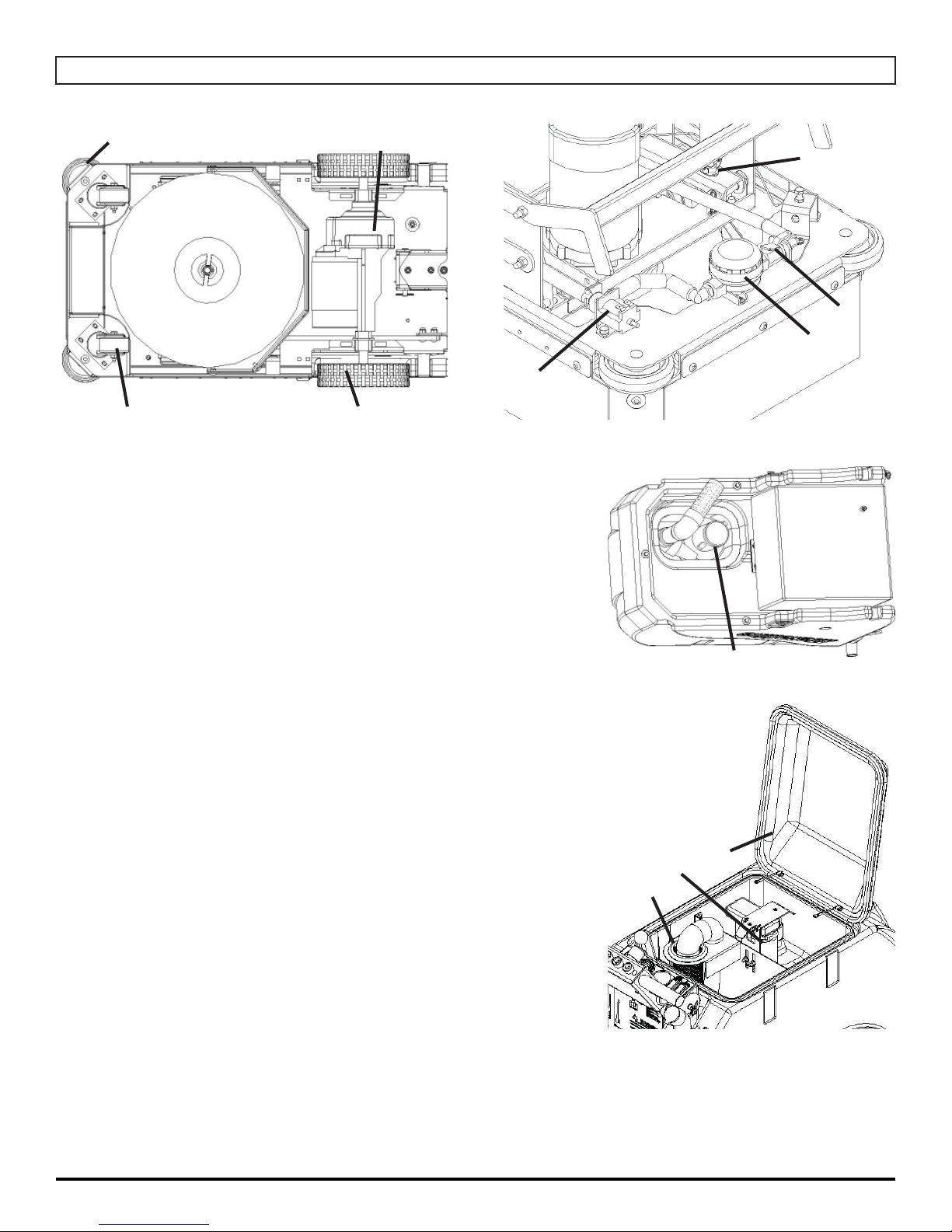
MACHINE COMPONENTS
2
1
1. CASTER: Twin Casters for stability
2. WALL ROLLERS: Helps protect machine when scrubbing
near walls
3. MAIN TIRES: Drive Tires
4. TRACTION DRIVE: Propels machine forward/reverse
5. SOLUTION FILTER: Filters water solution prior to scrubbing
4
3
8
6
5
7
6. SOLUTION FLOW SHUT OFF VALVE: Meters solution rate
(GPM)
7. SOLUTION FLOW VALVE: Turns solution ON / OFF (Turns
off when motor stops)
8. “PAD ASSIST” DRIVE ADJUSTMENT KNOB: Adjusts
amount of offset being applied to Brush
9. VACUUM MOTOR: Creates vacuum for Tank / Squeegee
10. “DRAIN SAVER” STRAINER: Helps prevent clogging of
Drain Ports
11. VAC SCREEN: Protects Vacuum Motor from debris
12. RECOVERY LID: Used for fl ushing out Recovery Tank area
with fresh water
9
12
11
10
- 8 - MICROMAG-OP-EN
Page 9
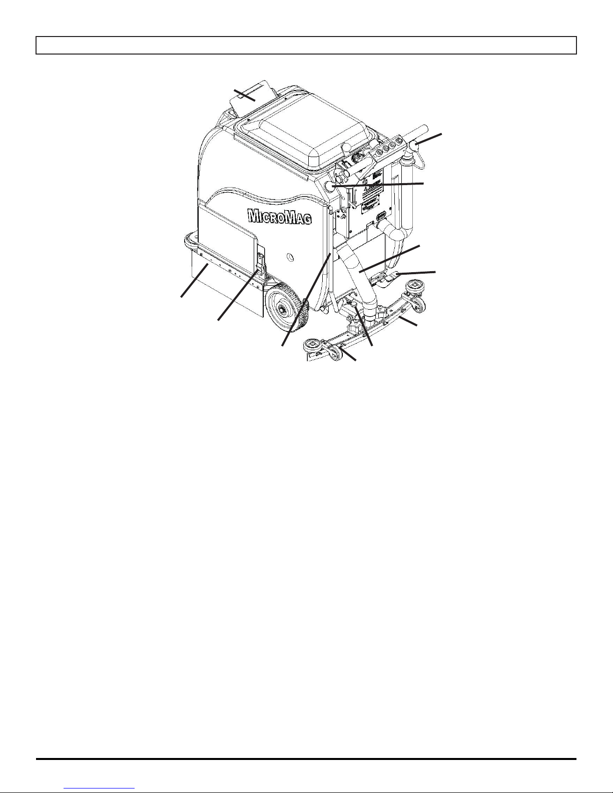
MACHINE COMPONENTS
1
11
10
9
8
2
3
4
1. FRONT SOLUTION FILL POINT/LID: Front fi ll port for fi lling Solution Tank
2. FRAME CURTAIN: Helps control water from splashing.
3. TANK LATCH: Secures Tank to frame
4. SOLUTION SIGHT TUBE AND DRAIN HOSE: Displays how much clean water is in the
Tank and drains clean water
5. ADJUSTABLE SQUEEGEE HEIGHT WHEELS: Height of wheels adjust to height of
Squeegee
6. SQUEEGEE PITCH ADJUSTMENT: Adjusts pitch of Squeegee - Defl ection should be
even across entire blade
7. SQUEEGEE BLADE: Recovers dirty water from fl oor to be recovered by Vacuum Hose
8. SCRUBDECK FOOTPEDAL (OPTIONAL): Used to raise and lower the Scrubdeck
9. VACUUM HOSE: Creates vacuum for Squeegee (NOTE: Keep free and clear of
blockage)
6
5
7
10. REAR SOLUTION FILL POINT: Rear fi ll port for fi lling Solution Tank
11. RECOVERY DRAIN HOSE: Allows for controlled draining of Recovery Tank
MICROMAG-OP-EN - 9 -
Page 10
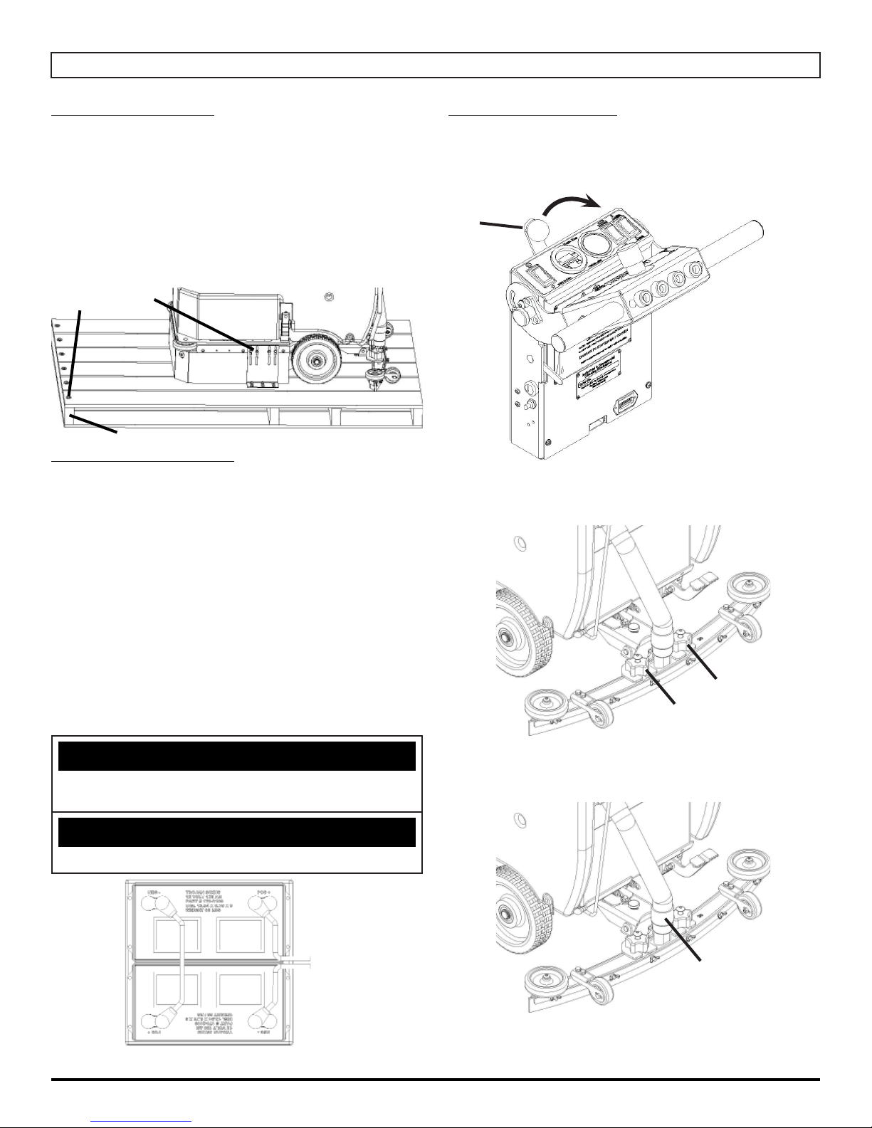
MACHINE SETUP
UN-CRATING MACHINE:
Carefully check the crate for any signs of damage and that
the Batteries are in the unit.
To un-crate the machine, remove banding strips from
around the crate. Take off the top and sides and dispose
properly. Remove brackets (A) from machine wheels.
Remove bolts (B) from pallet, then remove board (C).
Carefully roll the machine off of the base. Notify the carrier
immediately if concealed damage is discovered.
B
CONNECTING BATTERIES:
Your machine is equipped with (2×) 12-Volt/ 85 AH, (2×)
12-Volt/ 130 AH, or (2×) 12-Volt/ 150 AH Wet Lead Acid,
AGM, or Deep Cycle Batteries which form a 24 Volt
system.
(SEE PICTURE BELOW OR BATTERY DISCONNECT
LABEL FOR CORRECT CABLE CONNECTIONS)
A
C
ATTACHING SQUEEGEE:
1. Lower the Squeegee Mounting Plate by rotating the
Squeegee Lift Lever (A) in a clockwise motion (SEE
BELOW).
A
2. Loosen the two knobs (B) on the Squeegee and slide
them into the slots in the Squeegee Mounting Plate
(SEE BELOW).
1. Turn all switches to the OFF position and remove Key
(if machine is equipped with Optional Key Switch).
2. Attach all Battery Cables as shown below.
3. Turn ON main Key Switch and check the Battery
Condition Meter to ensure correct installation. Charge
Batteries if needed (SEE BATTERY CHARGING).
NOTICE
Batteries are a possible environmental hazard. Consult
your Battery supplier for safe disposal methods.
NOTICE
Orientation of Batteries is critical for cables to reach.
24 VOLTS
B
B
3. Tighten the two knobs and connect the Vacuum Hose
(C) from the machine to the Squeegee (SEE BELOW).
C
- 10 - MICROMAG-OP-EN
4. You may have to adjust the Squeegee Pitch (SEE
ADJUSTING SQUEEGEE ON THE NEXT PAGE)
Page 11
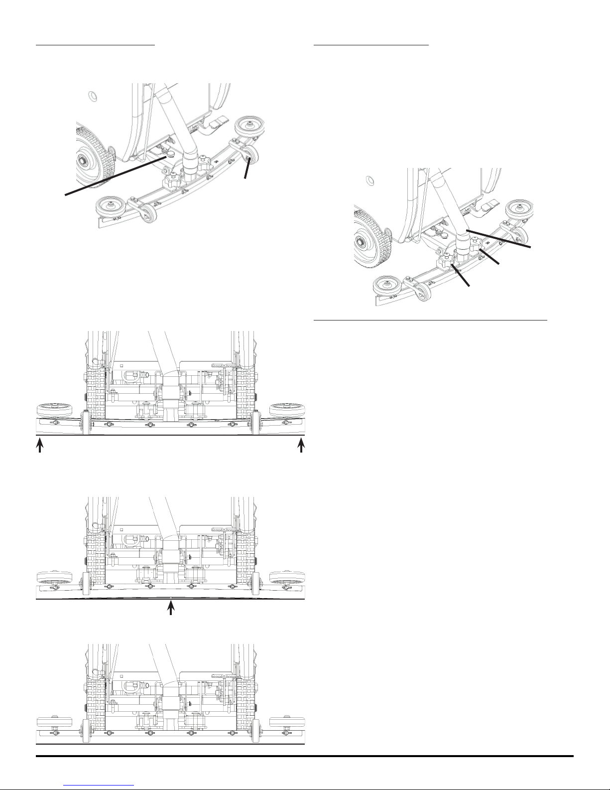
ADJUSTING SQUEEGEE:
1. Turning Adjustment Knob (A) clockwise (tightening)
will lower tips and raise the center of the Squeegee
(SEE BELOW).
B
A
2. Adjustable Wheel (B) (SEE ABOVE) has 3 holes. The
closer to the machine the wheel is, the further from
the ground the wheel becomes. The farther from the
machine the wheel is, the closer to the ground the
wheel becomes.
3. This Squeegee is adjusted too far back and will not
pick up on the corners (SEE BELOW).
NOTE: Tips off of the fl oor.
REMOVING SQUEEGEE:
1. With the Squeegee in the up position, turn machine
power off.
2. Disconnect Vacuum Hose (A) from Squeegee and
loosen both knobs (B) (SEE BELOW).
3. Pull Squeegee assembly backward from the lifting
carrier.
4. Inspect or repair as needed and reinstall.
A
B
B
REPLACING OR ROTATING SQUEEGEE BLADES:
FOR SAFETY: Before leaving or servicing the machine,
stop on a level surface, turn off machine and remove key.
4. This Squeegee is adjusted too far forward and will not
pick up in the center (SEE BELOW).
NOTE: Center spaced off the fl oor.
5. This Squeegee is adjusted just right with good
defl ection across the entire rear Blade (SEE BELOW).
1. Remove the Squeegee Assembly from the machine.
Remove Blade Retainer Strap and remove Squeegee
Blade.
2. Rotate the Squeegee to new edge position or replace
as required.
3. Install Blade on the locating pins of Squeegee
Assembly.
4. Install Squeegee Retainer Strap.
5. Fasten and lock knobs, starting in the center and
moving outwards.
MICROMAG-OP-EN - 11 -
Page 12
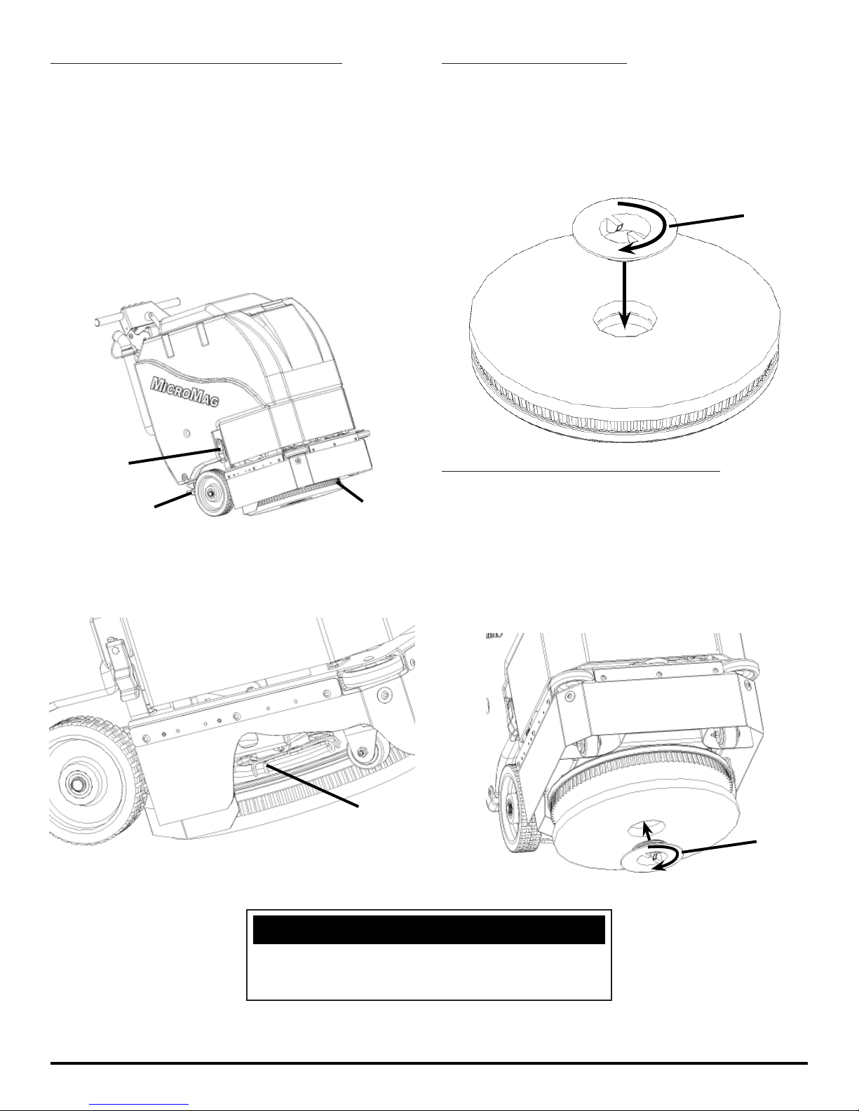
INSTALLING DISK PAD DRIVER OR BRUSH:
INSTALLING DRIVER PADS:
1. With empty Tanks, remove Squeegee and make sure
the Tank latches (A) are locked on.
2. Lower the Scrubdeck by depressing the Scrubdeck
Switch (B) on the Handlebars and turn OFF the
machine (for machines with manual foot-pedal
Scrubdeck lifting - lower manually). Remove Key if
Option equipped.
3. Tip machine back by pulling back on Handlebar and
allowing the machine to rest on the Triangle Squeegee
Plate (C).
A
1. Select the correct Pads that best meet your cleaning
application needs. Consult your local dealer for
assistance.
2. Pad Installation: Attach Pads to Pad Drivers before
connecting Drivers to Motor Hub. Screw center clip (E)
into place (SEE BELOW).
E
REPLACING DRIVER PADS ON MACHINE:
C
4. Attach brushes or pads to motor drives. Squeeze the
scissor locking device and lift brush up on to the Motor
Drive Hub. Make sure the scissors close and lock on
to the Brushes (SEE BELOW).
5. With Brushes locked into place, tip machine back down
to a level surface.
B
D
1. Select the correct Pads or Brushes that best meet
your cleaning application. Consult your local dealer for
assistance.
2. With empty Tanks and Squeegee removed, tip
machine back and rest on Triangle Plate.
3. Attach Pads to Pad drivers and screw center clip (F)
into place (SEE BELOW).
F
NEVER place aggressive Pads (Maroon Prep, Dominator
HD Strip, etc.) directly onto the Grip Face. Always use
Red or Blue Spacer pad to prevent Grip Face damage.
- 12 - MICROMAG-OP-EN
NOTICE
Page 13
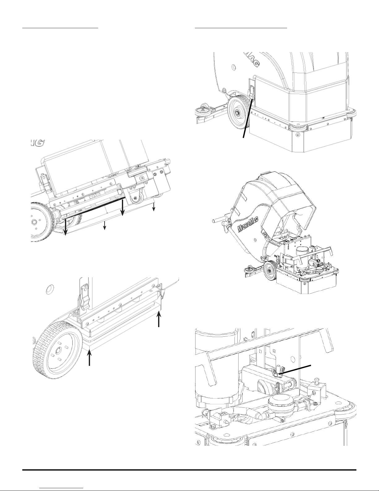
INSTALLING EDGE PADS:
ADJUSTING PAD ASSIST BIAS:
1. Turn off machine power (make sure that scrub deck
is raised off of the ground). Remove Key if Option
equipped.
2. With empty Tanks and Squeegee removed, tip machine back and rest on Triangle Plate.
3. Select the correct Pads that best meet your cleaning
application. Consult your local dealer for assistance.
4. Remove any Pad previously attached to the EDGE
Grip Face by pulling down from the corners (SEE
BELOW).
1. Release (2×) Tank latches (A) (SEE BELOW).
A
2. Tip Tank back (SEE BELOW).
5. Once Grip Face is clear of any Pads, place Pad wanted for application centered on the Grip Face (This will
leave a ½'' overhang on all sides) (SEE BELOW).
6. Press upwards on the Pad to secure it in place.
7. With Pad attached securely to Grip Face of EDGE
Deck, tip the machine back to standard sitting position
and reattach Squeegee for machine to be ready to
use.
3. Turn the Pad Assist Adjustment wing nut (B) to the
right to increase bias and to the left to decrease (SEE
BELOW).
B
MICROMAG-OP-EN - 13 -
Page 14
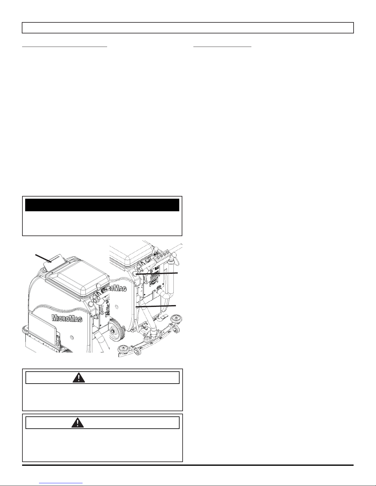
MACHINE OPERATION
PRE-CLEANING CHECKLIST:
Read and understand the Safety Messages section on
Pages 3 and 4 before operating the machine.
1. Check Battery Condition Gauge on the Control Panel.
Make sure Batteries are fully charged before using.
2. Check the condition of the Pads or Brushes.
3. Check the condition of the Squeegee Blades.
4. Raise the Scrubdeck and Squeegee before
transporting then transport the machine to the fi lling
station.
5. Turn the machine OFF.
6. Fill the Tank with up to 10 gallons of clean water
either at the front fi ll port (A) or rear fi ll port (B) (SEE
BELOW).
7. Add APPROVED cleaning chemical to the Tank.
Use the proper dilution ratio indicated on the bottle.
Contact us at 1(800)-634-4060 or +011-262-681-3583
if unsure.
NOTICE
The clear tube (Solution Sight Tube) (C) at the rear of the
machine indicates the amount of water in the tank (SEE
BELOW).
A
OPERATING HINTS:
1. Observe the amount of solution the machine is
dispensing on the fl oor and adjust to the desired fl ow.
To increase the solution fl ow rate, pull the Solution
Control Lever down. To shut the solution OFF
completely, just release the Drive button, or use dash
mounted switch.
2. Keep an eye on the clear Vacuum Cover to make sure
that there is not any foamy buildup in the Recovery
Tank. If excess foam begins to develop, pour a
recommended foam control solution into the Recovery
Tank. Foam is usually an indication of excessive soap.
3. Always operate at lower speeds when scrubbing
around walls and objects. You should reduce the
speed to maintain control when turning.
4. If squeegee starts to streak, raise and wipe the Blades
with a clean cloth. If the problem continues, check the
Squeegee Blades for wear or damage and rotate if
needed. You may need to pre-sweep before scrubbing.
(Only Use OEM Parts)
5. Change or turn over Pads when dirty.
6. Stay clear of objects protruding from the fl oor such as
sockets, grates, etc, for they will damage the Pads and
Squeegee Blades.
7. Always keep an eye on your gauges. They let you
know the status of a particular system at a glance. If
your Battery Gauge is reading low you much stop
immediately and recharge. Running the batteries dead
B
C
will result in damage to the batteries.
8. When you run out of solution, raise the Scrubdeck and
continue to vacuum the remaining water until it is all
consumed. The Solution Sight Tube is used to indicate
the level of detergent remaining in the Tank.
9. When you are ready to stop, raise the Scrubdeck, turn
OFF the Solution Switch, raise the Squeegee and
drive the machine back to the charging area. Be sure
to drain both Tanks before storing the machine.
DANGER
EXPLOSION RISK! Flammable materials can
cause an explosion or fi re. Do not use fl ammable
materials in tank or pick up.
CAUTION
TO AVOID DAMAGE TO THIS MACHINE:
• Use approved detergents only
• Water temperature must not exceed 130˚F/54˚C
• Do not use high-percentage bleach mixture
- 14 - MICROMAG-OP-EN
Page 15
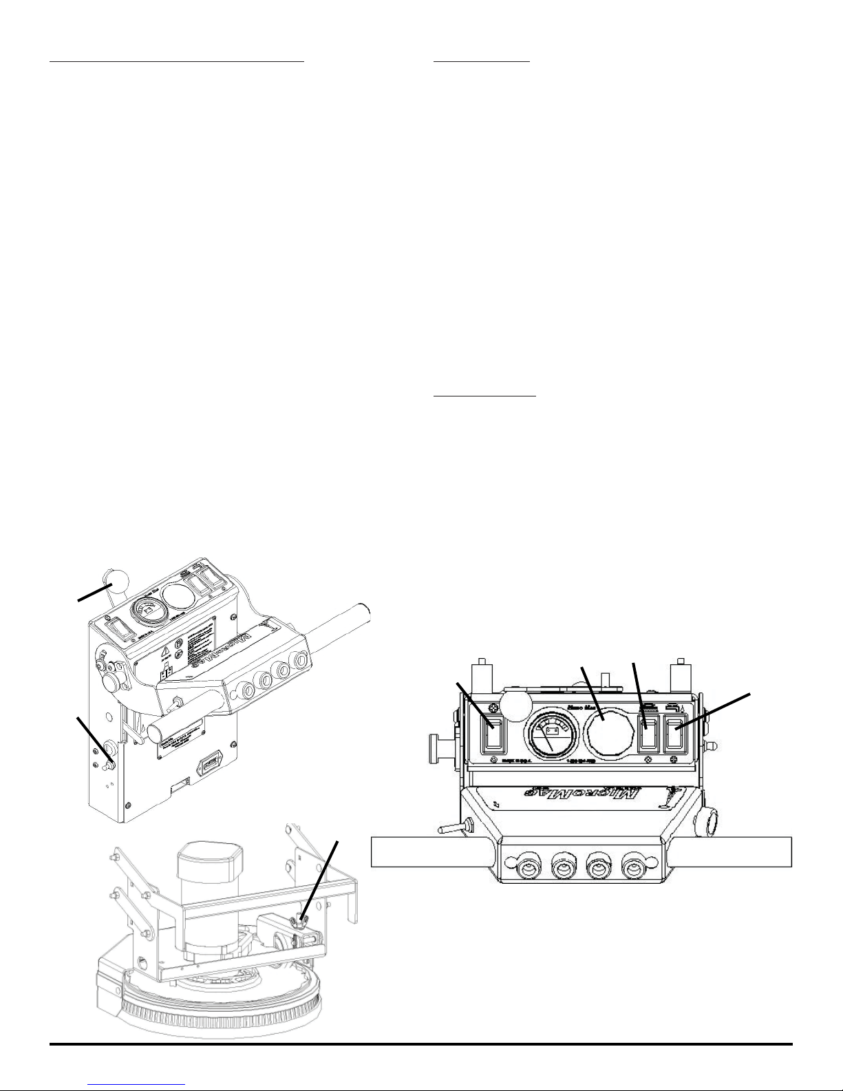
ONE PASS SCRUBBING (PAD ASSIST):
1. Turn on machine Power Switch (A) (if machine is
equipped with Optional Key Switch), make sure
the Speed Control Knob (B) is at a lower setting.
2. Lower the Squeegee by rotating the Squeegee Lift
Lever (C) all the way to the right. Turn on Vacuum
Motor with Vacuum Switch on Control Panel (D).
3. Lower Scrubdeck head to the fl oor by
pressing the Scrubdeck Switch on the
Control Panel (E) (or by manually lowering
the Scrubdeck with Foot Pedal option).
4. Move the Solution Flow Lever (F) to
regulate the amount of solution fl ow.
5. Begin scrubbing by pressing the Scrubdeck switch
button (F) on the dash board or use (optional)
green Drive Control Buttons. Adjust the Pad Assist
adjustment knob (B) to the desired setting.
6. Once the machine begins to move, check the
Down Pressure Gauge (G) (Optional). Start
scrubbing at the middle. Do not scrub in
the red, or the Circuit Breaker will blow.
7. To operate the machine in reverse, simply
pull the Reverse switch (H) back towards
the Handlebar. The reverse speed is set to
approximately 50% of the forward speed.
8. To stop the machine, shutoff Scrubdeck
switch (F) and Vac Motor (D).
SCRUB ONLY:
1. Turn on machine Power Switch (A) while making sure
the Speed Control Knob (B) is at a lower setting.
2. Lower Scrubdeck head to the fl oor by pressing
the Scrubdeck Switch on the Control Panel (E).
3. Move the Solution Control Lever (F) to
regulate the amount of solution fl ow.
4. Begin scrubbing by pressing one of the green
Drive Buttons (G) on the Handlebars. Adjust the
Speed Control Knob (B) to the desired setting.
5. To operate the machine in reverse, simply
pull the Reverse Switch (H) back towards
the Handlebar. The reverse speed is set to
approximately 50% of the forward speed.
6. To stop the machine, let go of the Drive Buttons (G).
VACUUM ONLY:
1. Turn on machine Power Switch (A) while making sure
the Speed Control Knob (B) is at a lower setting.
2. Lower the Squeegee by rotating the Squeegee Lift
Lever (C) all the way to the right. Turn on Vacuum
Motor with Vacuum Switch on Control Panel (D).
3. Begin vacuuming by pressing one of the green
Drive Buttons (G) on the Handlebars.
C
G
F
D
E
A
B
MICROMAG-OP-EN - 15 -
Page 16
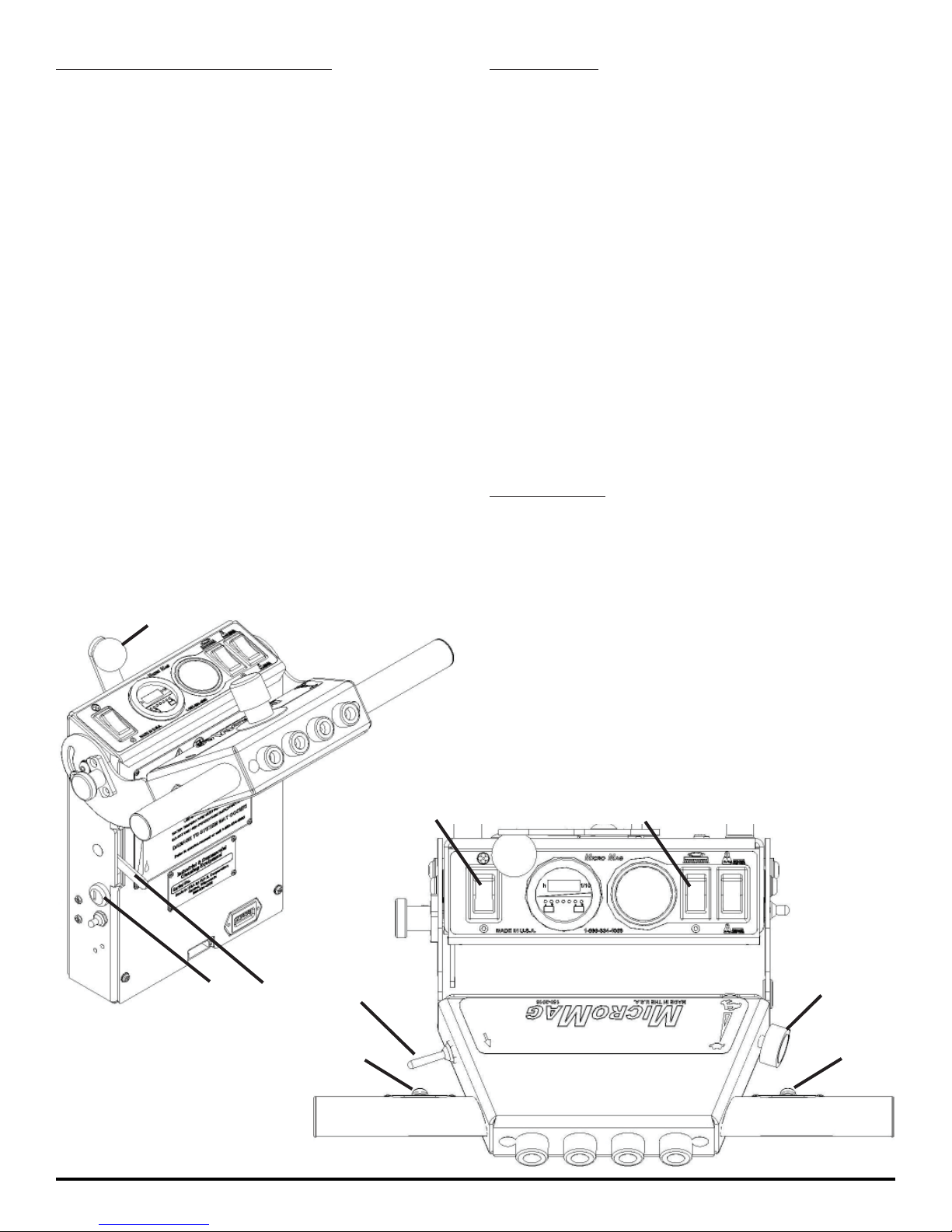
ONE PASS SCRUBBING (TRACTION):
SCRUB ONLY:
1. Turn on machine Power Switch (A), make sure the
Speed Control Knob (B) is at a lower setting.
2. Lower the Squeegee by rotating the Squeegee Lift
Lever (C) all the way to the right. Turn on Vacuum
Motor with Vacuum Switch on Control Panel (D).
3. Lower Scrubdeck head to the fl oor by pressing
the Scrubdeck Switch on the Control Panel (E).
4. Move the Solution Flow Lever (F) to
regulate the amount of solution fl ow.
5. Begin scrubbing by pressing one of the green
Drive Buttons (G) on the Handlebars. Adjust the
speed control knob (B) to the desired setting.
6. To operate the machine in reverse, simply
pull the Reverse switch (H) back towards
the Handlebar. The reverse speed is set to
approximately 50% of the forward speed.
7. To stop the machine, let go of the Drive Buttons (G).
1. Turn on machine Power Switch (A) while making sure
the Speed Control Knob (B) is at a lower setting.
2. Lower Scrubdeck head to the fl oor by pressing
the Scrubdeck Switch on the Control Panel (E).
3. Move the Solution Control Lever (F) to
regulate the amount of solution fl ow.
4. Begin scrubbing by pressing one of the green
Drive Buttons (G) on the Handlebars. Adjust the
Speed Control Knob (B) to the desired setting.
5. To operate the machine in reverse, simply
pull the Reverse Switch (H) back towards
the handle bar. The reverse speed is set to
approximately 50% of the forward speed.
6. To stop the machine, let go of the Drive Buttons (G).
VACUUM ONLY:
1. Turn on machine Power Switch (A) while making sure
the Speed Control Knob (B) is at a lower setting.
2. Lower the Squeegee by rotating the Squeegee Lift
Lever (C) all the way to the right. Turn on Vacuum
C
D
A
F
H
Motor with Vacuum Switch on Control Panel (D).
3. Begin vacuuming by pressing one of the green
Drive Buttons (G) on the Handlebars.
E
B
- 16 - MICROMAG-OP-EN
G
G
Page 17
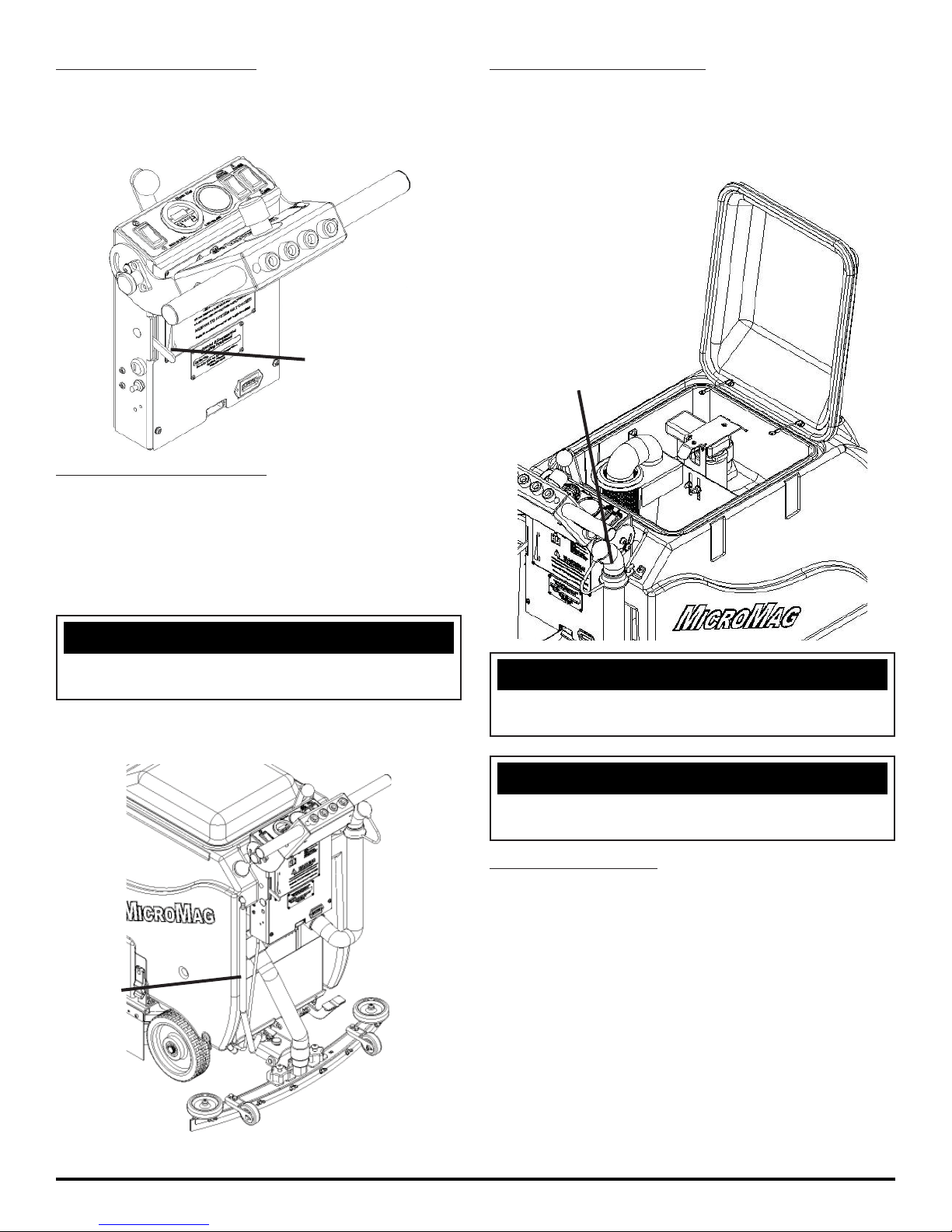
ADJUST SOLUTION FLOW:
DRAINING RECOVERY TANK:
1. Push down on the Solution Flow Lever (A) to increase
the solution fl ow and push up on the lever to decrease
solution fl ow (SEE BELOW).
A
DRAINING SOLUTION TANK:
To drain unwanted cleaning solution from the Solution
Tank, perform the following steps:
(SEE BELOW)
Always empty Recovery Tank when refi lling the Solution
Tank. You can refi ll the Solution Tank while the Recovery
Tank is draining. To drain the Recovery Tank remove Drain
Hose (B) from hook at rear of Tank and pop off cap (SEE
BELOW). Rinse with fresh water.
B
1. Pull the clear Sight Tube/Drain
Hose (A) off barbed fi tting.
NOTICE
Get Supervisor APPROVAL fi rst and drain at
APPROVED locations only.
2. Rinse out Tank and Solution Flow
system with clean water.
A
NOTICE
Leave Recovery Lid open while draining Tanks. Rinse
thoroughly.
NOTICE
Get Supervisor APPROVAL fi rst and drain at
APPROVED locations only.
OPEN RECOVERY LID:
1. Rotate Tank Lid (B) forward and full open to rest
in a tipped open position (SEE ABOVE).
MICROMAG-OP-EN - 17 -
Page 18
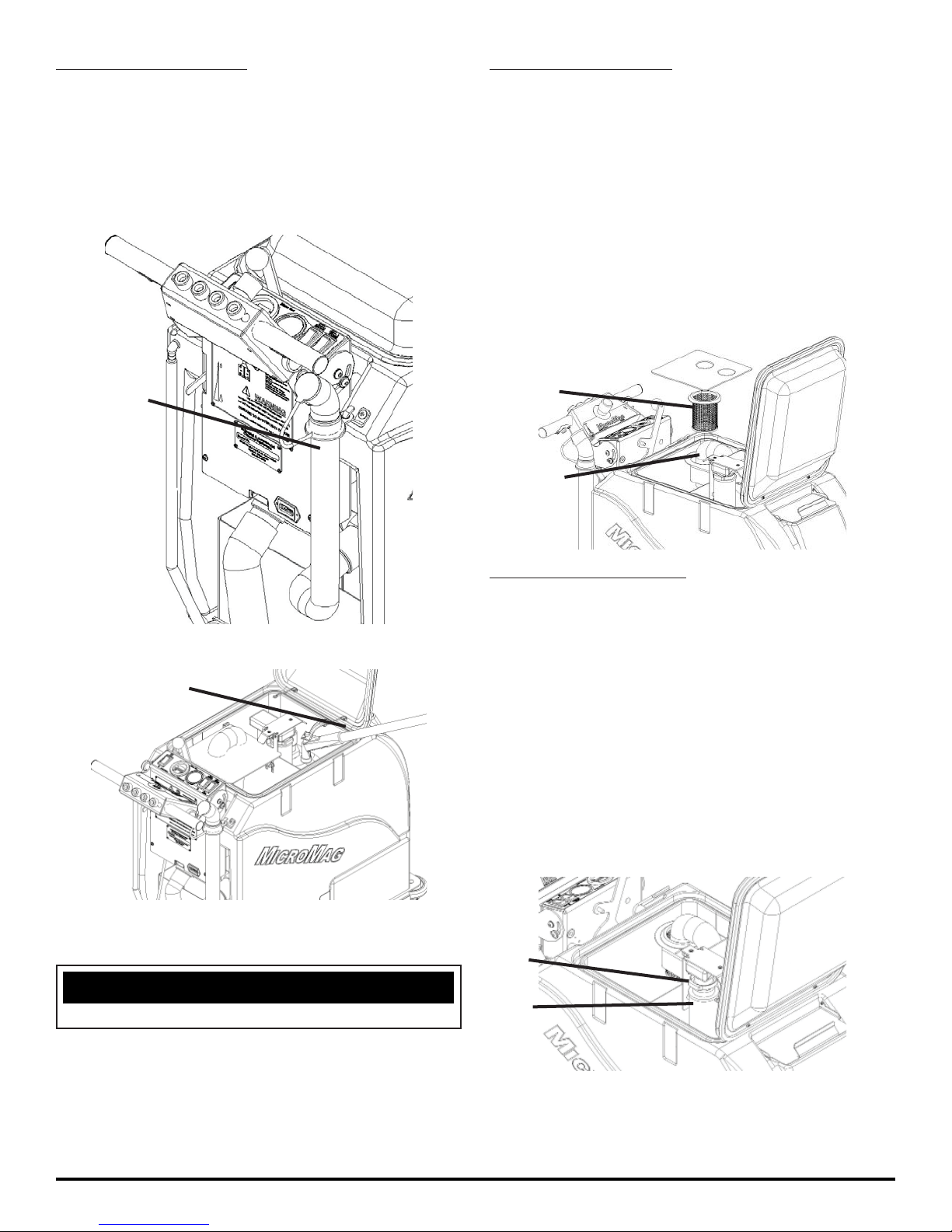
FLUSH RECOVERY TANK:
CLEAN “DRAIN SAVER”:
1. Rinse the Recovery Tank after every use
(A). This will prevent heavy build-up on the
bottom of the tank, foul odors as well as
clogging of the drain hose (SEE BELOW).
2. Remove Drain Hose (B) and open to allow for
drainage of the Recovery Tank (SEE BELOW).
B
With Recovery Lid open and Tank fully drained:
1. Remove 2'' Squeegee Intake Hose (A) from
“Drain Saver” strainer (B) (SEE BELOW).
2. Remove stainless screen and dispose of debris.
3. Rinse screen with fresh water from the
outside while holding the screen upside
down. This will allow for better cleaning.
4. Replace the screen into the bracket.
5. Replace 2'' Squeegee Intake Hose.
B
A
3. Flush Recovery Tank with water hose.
A
4. After rinsing, reattach the Drain Hose
(B) on hook (SEE ABOVE).
NOTICE
Keep water off of Control Panel.
CLEAN VACUUM SCREEN:
With Recovery Lid open and Tank fully drained:
1. Remove Vacuum Screen retaining
clip (C) (SEE BELOW).
2. Pull Vacuum Screen and Float Ball
Assembly (D) off of the Vacuum Box.
3. Rinse with hot water.
4. Dry thoroughly.
5. Replace the Vacuum Screen onto box.
6. Replace and tighten retaining clip.
C
D
- 18 - MICROMAG-OP-EN
Page 19
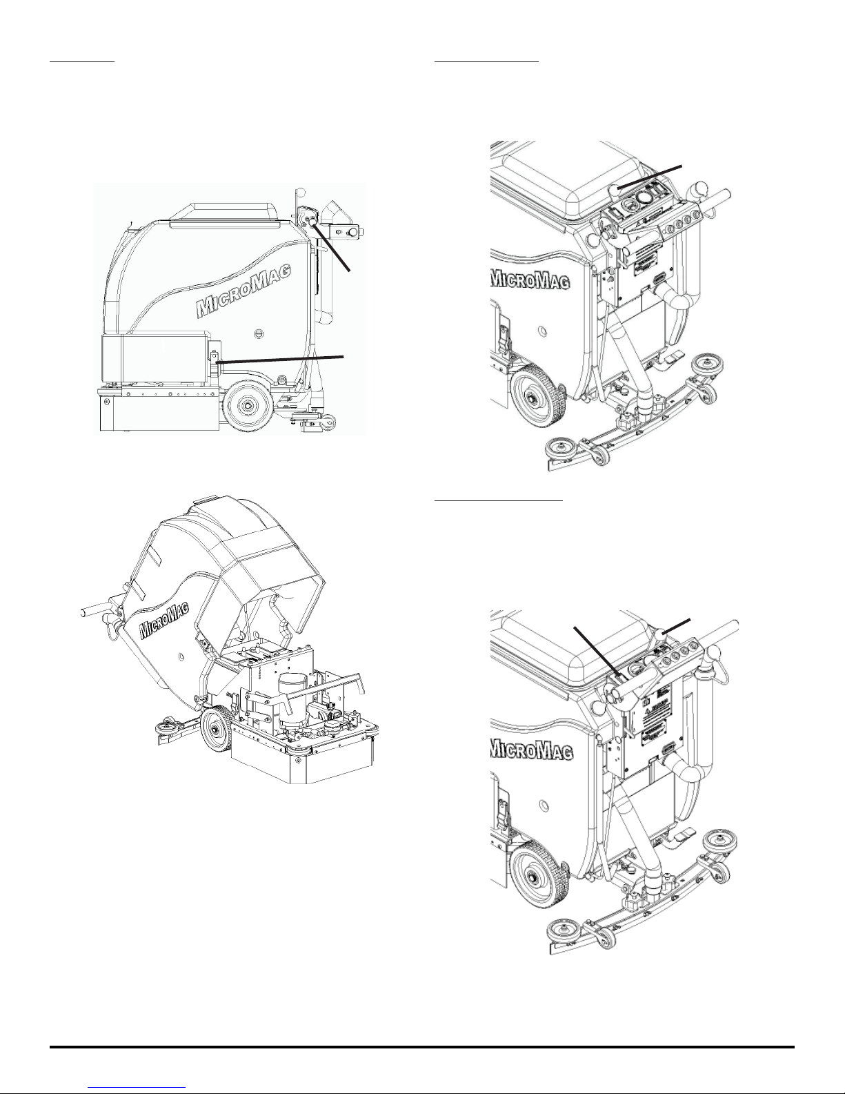
TIP TANK:
SQUEEGEE UP:
1. Fully drain Solution Tank and the Recovery Tank.
2. Remove Squeegee or place in center.
3. Rotate Handlebar down 90° with the Handlebar
Adjustment Knob (A). Unlatch Tank Latch (B)
on each side of the machine (SEE BELOW).
A
B
4. Tip Tank Back carefully until supported
by strap as well as the Rubber Grommets
on the Handlebar (SEE BELOW).
1. To raise the Squeegee off the fl oor, rotate
Squeegee Lift Lever (A) counter-clockwise
all the way to the left (SEE BELOW).
A
SQUEEGEE DOWN:
1. To Lower the Squeegee to the fl oor, rotate Squeegee
Lift Lever (B) clockwise all the way to the right. To
turn on Vacuum Motor use the Vacuum Switch
(C) on the Control Panel (SEE BELOW).
C
B
MICROMAG-OP-EN - 19 -
Page 20
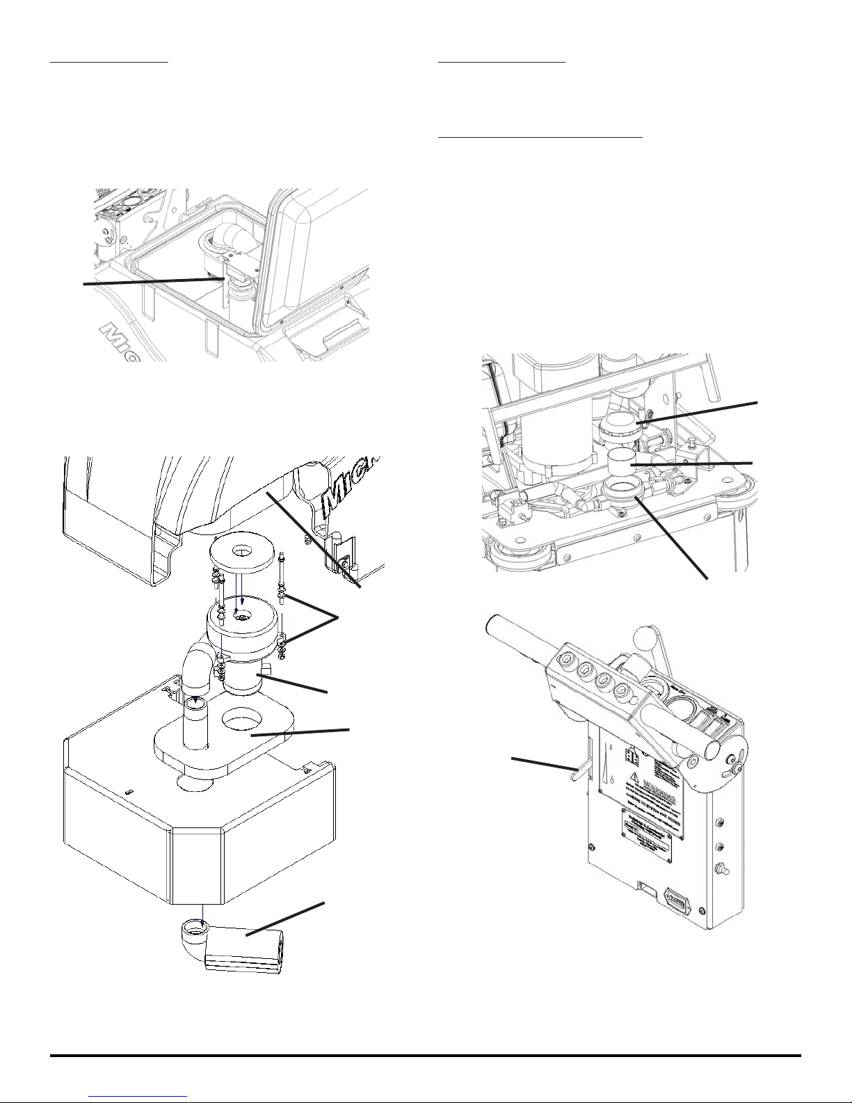
VACUUM MOTOR:
SOLUTION FILTER:
1. The machine is equipped with a 24 volt,
.75HP Vacuum Motor (A) (SEE BELOW).
2. If foam or water gets past the Recovery Tank’s
Vac Screen/Ball system, adjust the bracket
(B) in the Tank upwards (SEE BELOW).
B
3. The Vacuum Motor has an (Optional)
“Foam Muffl er” (C), sound reduction walls
(D) and vibration dampeners (E) that are
available to quiet machine operation.
The solution system has an “Inline Filter” (A) to fi lter out
cleaning solution prior to scrubbing (SEE BELOW).
CLEANING SOLUTION FILTER:
1. To clean the Solution Filter, fi rst close Solution Flow
Valve by moving lever (B) upwards. Then unscrew
the clear cap (C) from house (A) and remove
the stainless steel screen (E) (SEE BELOW).
2. Rinse any debris from the screen with clean water.
3. Reinstall screen and screw cap back on tightly.
4. Re-open valve.
C
E
D
E
A
D
B
C
A
- 20 - MICROMAG-OP-EN
Page 21
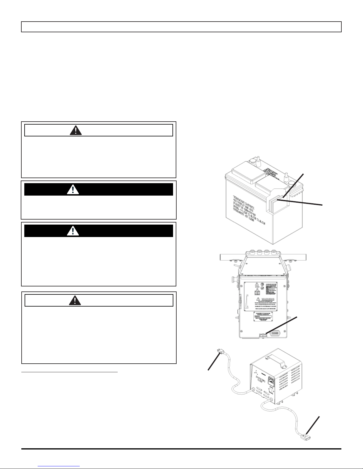
BATTERY CHARGING
Charger Specifi cations
• Output voltage of 24 Volts
• Output current of 12 amps max
• Input voltage of 110 Volts/ 60 Hz
(220V/50 Hz available)
• Automatic shut off circuit
• Made for Deep Cycle Batteries
DANGER
Explosive hydrogen gas forms when Batteries are
charging. An open fl ame or spark can cause this
gas to explode. Serious personal injury or property damage could occur. Only charge the Batteries
in this machine in a well ventilated area.
WARNING
Before you service a Battery, always wear face protec-
tion, protective gloves and protective clothing. Battery
acid or battery explosion can cause serious injuries.
4. First, plug the red 50 Charger plug into the
machine’s Charger Port (B). While the Charger plug
is connected, plug the charger power cord into a
grounded 110 Volt standard wall outlet (C).
5. The Charger will automatically begin charging and
automatically shut off when fully charged (check
Battery gauge).
6. After the Charger has turned off - First, unplug the
Charger from the wall outlet. Second, unplug the red
50 Charger plug from the machine.
7. Recheck the cell level after charging. If needed, add
distilled water up to the correct level. Be certain to
replace the caps securely and to wipe off the top of the
batteries with a clean cloth.
WATER LEVEL SHOULD BE
1/8'' ABOVE PLATES
A
WARNING
The Batteries in this machine contain sulfuric
acid, which causes burns to skin. If battery acid
contacts clothing or skin, rinse the effected area
with cold water immediately. If battery acid gets
on your face or in your eyes, fl ush the area immediately with cold water and seek medical attention.
CAUTION
Always use the automatic battery charger provided by the manufacturer of this machine to charge
the Batteries of this machine. It is designed to
charge the Batteries at the appropriate rate. If
you must use a different charger, disconnect the
Batteries before charging to avoid damage to the
electronic speed controller.
EXTERNAL BATTERY CHARGING:
1. Transport machine to a well ventilated area for
charging.
2. Turn the machine off. Tip back Tank.
3. Check the water in each Battery (A). Do not charge
the machine unless the water is slightly higher than
the plates. If needed, add enough distilled water to
just slightly cover the plates. Be careful not to over fi ll.
Batteries can overfl ow during charging. Replace caps
before charging.
B
C
B
MICROMAG-OP-EN - 21 -
Page 22
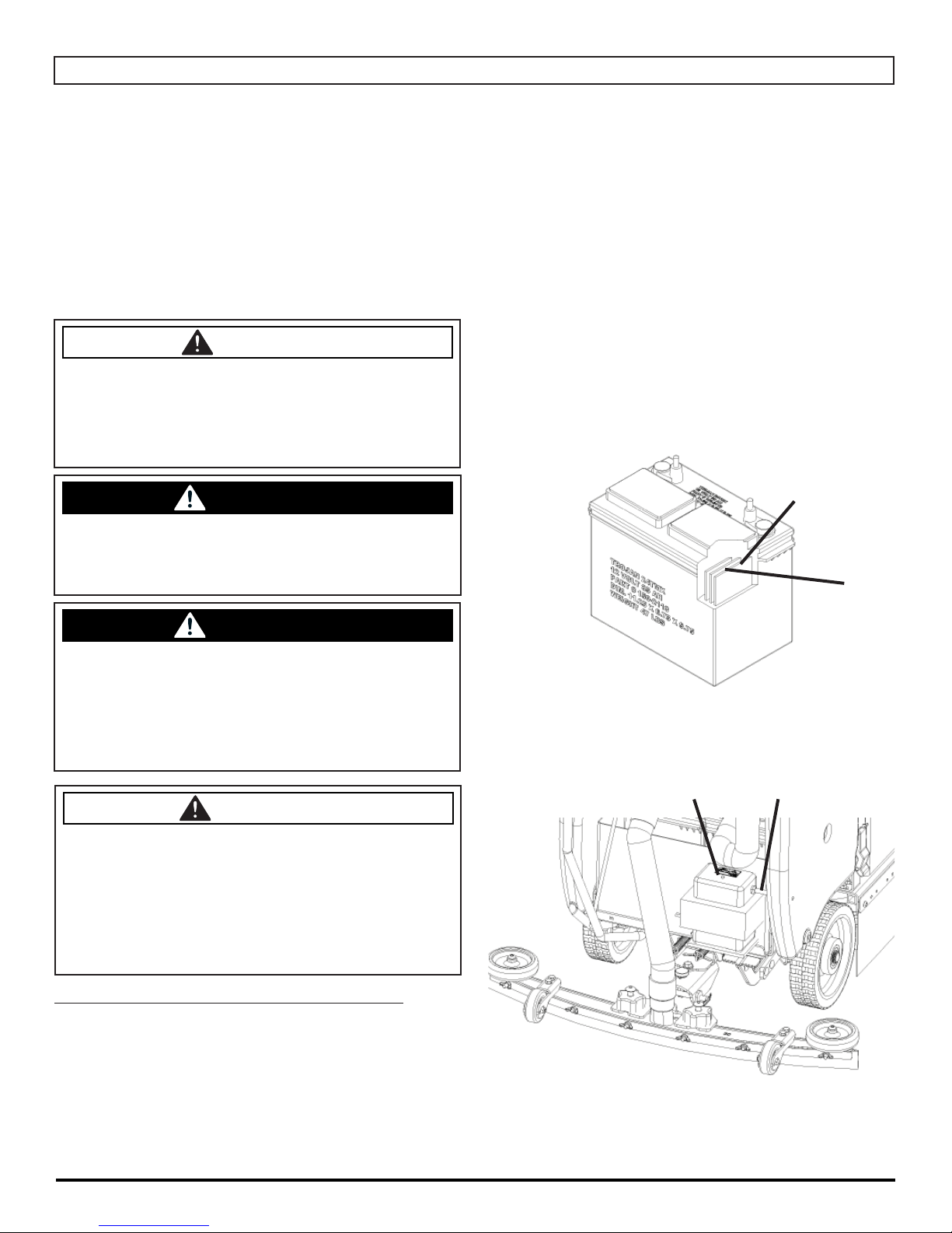
ON-BOARD CHARGER
Charger Specifi cations
• Output voltage of 24 Volts
• Output current of 12 amps max
• Input voltage of 110 Volts/ 60 Hz
(220V/50 Hz available)
• Automatic shut off circuit
• Made for Deep Cycle Batteries
DANGER
Explosive hydrogen gas forms when Batteries are
charging. An open fl ame or spark can cause this
gas to explode. Serious personal injury or property damage could occur. Only charge the Batteries
in this machine in a well ventilated area.
WARNING
Before you service a battery, always wear face
protection, protective gloves and protective clothing.
Battery acid or battery explosion can cause serious
injuries.
Batteries can overfl ow during charging. Replace caps
before charging.
4. Plug the Charger power cord into a grounded standard
wall outlet (B).
5. The green Indicator Light (C) will come on and the
Charger will automatically begin charging. When
fi nished, the Charger will automatically shut off as well
as the green indicator light (check Battery gauge).
6. After the Charger has turned off, unplug the Charger
from the wall outlet.
7. Recheck the cell level after charging. If needed, add
distilled water up to the correct level. Be certain to
replace the caps securely and to wipe off the top of the
Batteries with a clean cloth.
WATER LEVEL SHOULD BE
1/8'' ABOVE PLATES
A
WARNING
The batteries in this machine contain sulfuric acid,
which causes burns to skin. If battery acid contacts clothing or skin, rinse the effected area with
cold water immediately. If battery acid gets on
your face or in your eyes, fl ush the area immediately with cold water and seek medical attention.
CAUTION
Always use the automatic battery charger provided by the manufacturer of this machine to charge
the batteries of this machine. It is designed to
charge the batteries at the appropriate rate. If
you must use a different charger, disconnect the
batteries before charging to avoid damage to the
electronic speed controller.
ON-BOARD BATTERY CHARGING (OPTIONAL):
1. Transport machine to a well ventilated area for
charging.
2. Turn the machine off. Tip back tank.
BC
3. Check the water in each battery (A). Do not charge
the machine unless the water is slightly higher than
the plates. If needed, add enough distilled water to
just slightly cover the plates. Be careful not to over fi ll.
- 22 - MICROMAG-OP-EN
Page 23
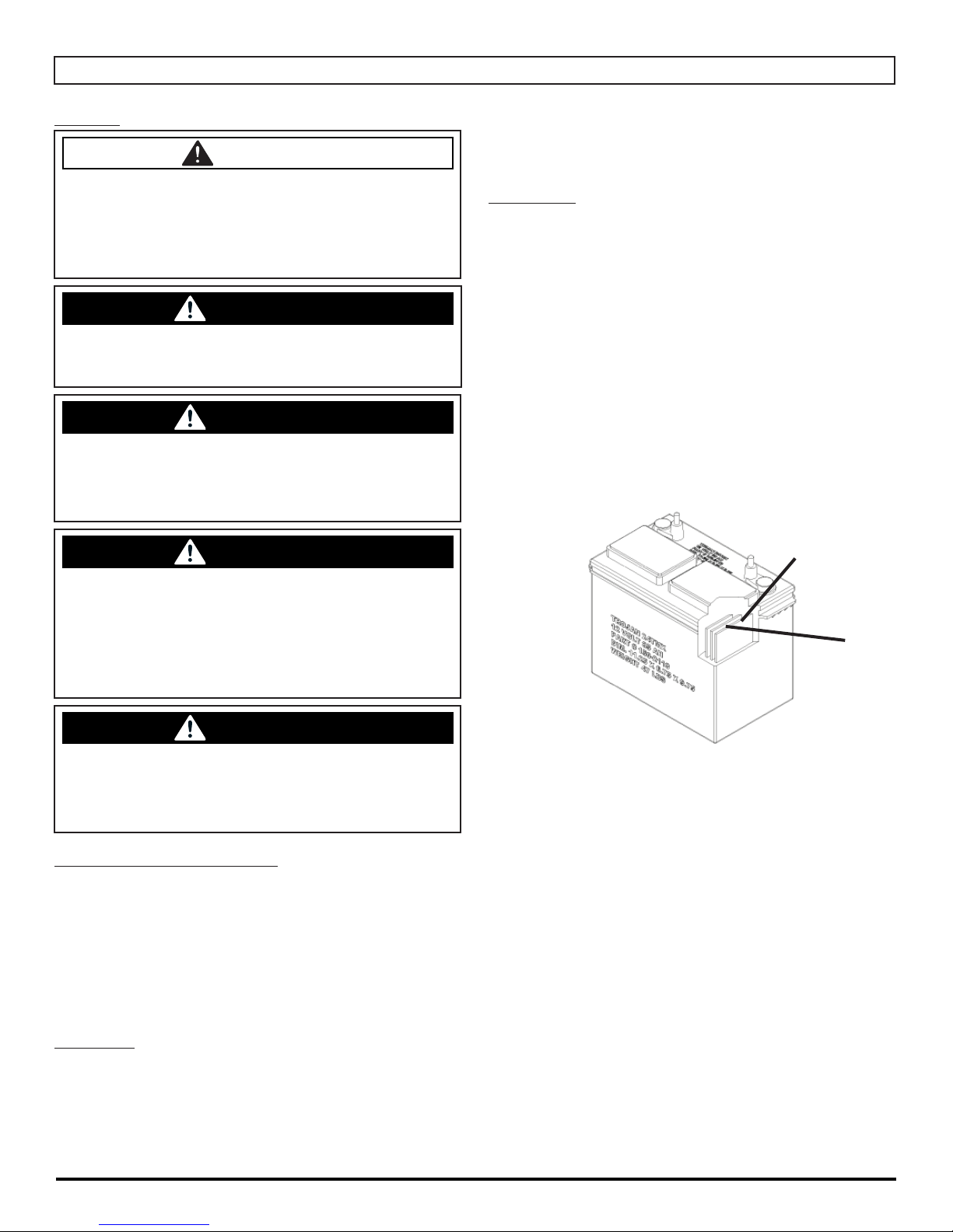
BATTERY MAINTENANCE GUIDE
SAFETY:
DANGER
Explosive hydrogen gas forms when Batteries are
charging. An open fl ame or spark can cause this
gas to explode. Serious personal injury or property damage could occur. Only charge the Batteries
in this machine in a well ventilated area.
WARNING
Before you service a Battery, always wear face protection, protective gloves and protective clothing. Battery
acid or battery explosion can cause serious injuries.
WARNING
The Batteries in this machine produce hazardous
voltage which can cause electrical shock, burns
and/or electrocution. Always disconnect Batteries
before servicing this machine.
WARNING
days
• Recharge Batteries before putting them back into
service
WATERING:
• Add water, NEVER ACID, to cells (distilled water
recommended).
• Do not over water
• Before charging the Batteries, only add water if the
plates are exposed. Add just enough water to cover
the plates, then charge the Batteries. Once fully
charged, add water to the proper level as indicated
below.
• For full charge plus series Batteries add water to the
maximum water level indicator (A).
• After watering, secure vent caps back on Batteries.
WATER LEVEL SHOULD BE
1/8'' ABOVE PLATES
The Batteries in this machine contain sulfuric
acid, which causes burns to skin. If battery acid
contacts clothing or skin, rinse the effected area
with cold water immediately. If battery acid gets
on your face or in your eyes, fl ush the area immediately with cold water and seek medical attention.
WARNING
Dress safely. Do not wear rings or metal wrist
watches when servicing this machine, as they can
cause an electrical short circuit which can cause
serious burns.
INSPECTION AND CLEANING:
• Keep Batteries clean and dry from residue
• Check that all vent caps are tight
• Use a solution of baking soda and water to clean if
acid residue on Batteries or corrosion on the terminals
• Protective spray of petroleum jelly should be applied to
terminals to reduce corrosion
A
STORAGE:
• Batteries should be fully charged prior to and during
storage
• Never store discharged Batteries
• Store batteries in a cool, dry place but never below
freezing - Recharge in storage a minimum of every 30
MICROMAG-OP-EN - 23 -
Page 24
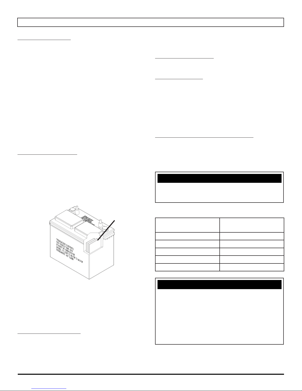
MAINTENANCE
DAILY MAINTENANCE:
1. Remove the clean Pads or Brushes. Never use
soiled Pads when cleaning. Replace Pads when they
become packed with residue.
2. Remove and clean debris from the fl oat shut-off screen
and Drain Saver located inside the Recovery Tank.
3. Drain and rinse Tanks thoroughly and fl ush out
Solution Feed to deck.
4. Inspect Vacuum Hose for any objects obstructing the
air fl ow.
5. Raise Squeegee and wipe Blades with a clean cloth.
Store Squeegee in the raise position to prevent
damage or setting of the Blades.
6. Wipe down machine if needed. Use a non-abrasive,
non-solvent cleaner or a clean damp cloth.
7. Recharge the Batteries if needed.
WEEKLY MAINTENANCE:
1. Check Battery water level in each cell of the Batteries
and fi ll as needed. Always use distilled water to refi ll
Batteries. Batteries should be fi lled approximately
3
⁄4'' to 1'' above the plates. Overfi lling will cause
the batteries to leak during charging. The charging
process creates gas bubbles inside the Battery, which
effectively increases the volume of the electrolyte.
if needed, 8-10 ft/lb MAX.
4. Grease caster swivel and Squeegee pivot point.
YEARLY MAINTENANCE:
Call your local dealer for yearly maintenance.
STORING MACHINE:
1. Be sure to fl ush the Tanks out completely. To
thoroughly fl ush out any solution chemicals in solution
line and valves, refi ll Solution Tank with a few gallons
of warm clean water and run machine until Tank is
empty.
2. Open the Recovery Tank lid to promote air circulation.
3. Raise Brush/Pad and Squeegee.
CHECKING BATTERY SPECIFIC GRAVITY:
Use a hydrometer to check the Battery specifi c gravity.
Checking Gravity:
• Hydrometer
• Battery
NOTICE
Do not take readings immediately after adding distilled
water. If water and acid are not thoroughly mixed, the
reading may not be accurate.
WATER LEVEL SHOULD BE
1/8'' ABOVE PLATES
2. Clean Battery tops to prevent corrosion.
3. Flip Scrubdeck brushes / pads.
4. Drain and rinse Tanks thoroughly. To thoroughly fl ush
out any solution chemicals in solution line valves, refi ll
Solution Tank with a few gallons of warm, clean water
and run the machine until Tank is empty.
MONTHLY MAINTENANCE:
1. Check Scrubdeck and Squeegee lifting cables for wear
and spring tension.
2. Check machine for water leaks and loose nuts and
bolts.
3. Check to see if battery cables are tightened. Tighten,
Check the hydrometer against this chart
SPECIFIC GRAVITY
@ 80°F (27°C)
1.265 100% Charged
1.225 75% Charged
1.190 50% Charged
1.155 25% Charged
1.120 Discharged
BATTERY
CONDITION
NOTICE
If the readings are taken when the battery electrolyte
is any temperature other than 80°F(27°C), the reading
must be temperature corrected. To fi nd the corrected
specifi c gravity reading when the temperature of the
battery electrolyte is other than 80°F(27°C): add (+) to
the specifi c gravity reading 0.004 (4 points), for each
10°F(6°C) above 80°F(27°C). Subtract (-) from the
specifi c reading 0.004 (4 points), for each 10°F(6°C)
below 80°F(27°C).
- 24 - MICROMAG-OP-EN
Page 25
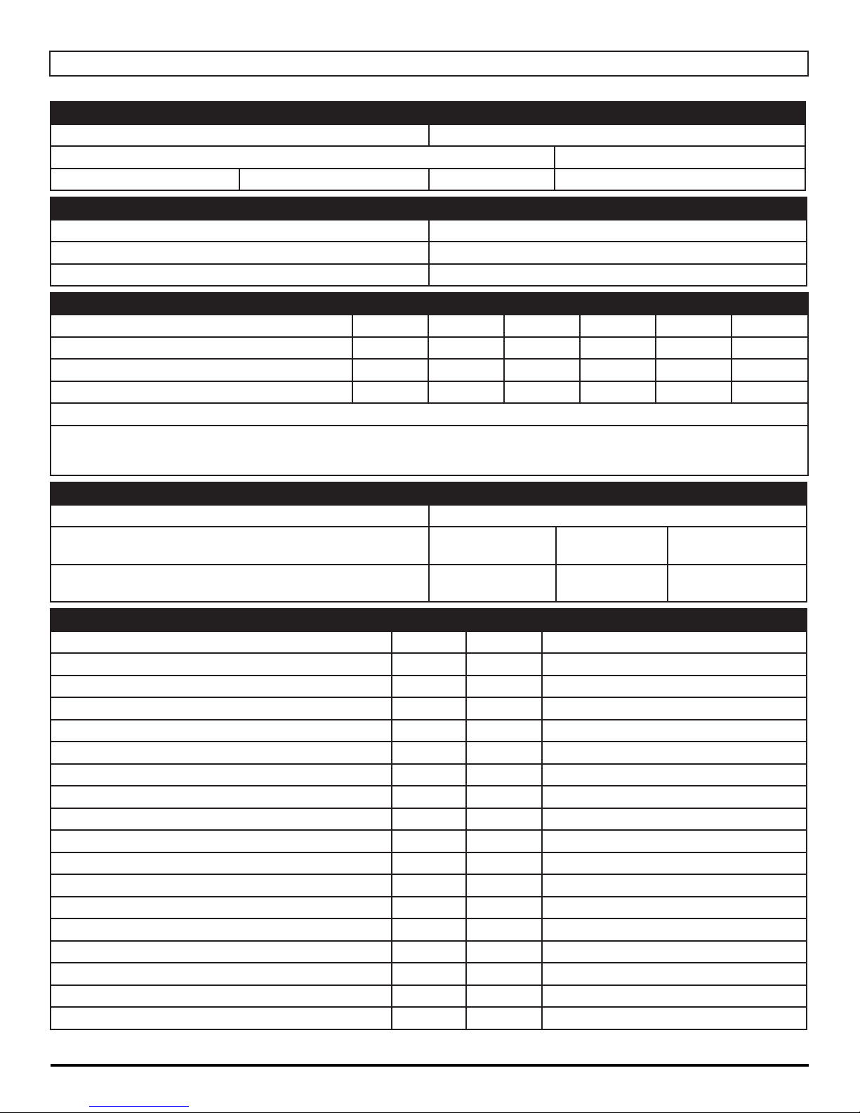
PM RECORDS
CUSTOMER INFORMATION
CUSTOMER EMAIL
ADDRESS PHONE
CITY STATE ZIP CONTACT
MACHINE INFORMATION
MODEL #: SERIAL #:
WORK ORDER#: HOUR METER:
ISOLATOR HOUR METER: RE-CHARGE COUNTER:
BATTERY CONDITION CELL 1 CELL 2 CELL 3 CELL 4 CELL 5 CELL 6
BATTERY 1 HYDROMETER
BATTERY 1 WATER CONDITION
BATTERY 2 HYDROMETER
BATTERY 2 WATER CONDITION
CLEAN BATTERY TOPS. CHECK BATTERY CABLE AND TERMINAL CONDITION.
NOTES:
PAD CONDITION
SCRUB BRUSH FIBER LENGTH ROTATED BRUSHES
DISK PAD DRIVER GOOD WORN NEEDS
REPLACEMENT
EDGE PAD GRIP FACE GOOD WORN NEEDS
REPLACEMENT
CHECK OPERATION AND CONDITION OF: IN SPEC REPAIR PROBLEM
KEY SWITCH (OPTIONAL)
BATTERY GAUGE
BRUSH SWITCH ON / OFF
REVERSE SWITCH (DRIVE ONLY)
SOLUTION LEVER
SOLUTION SOLENOID
SCRUBDECK ACTUATOR
BRUSH MOTOR
VACUUM SWITCH
VACUUM MOTOR PREFORMANCE
SQUEEGEE LIFT SYSTEM
SQUEEGEE ADJUSTMENT CABLE “HEIGHT”
SQUEEGEE BLADES
DRAIN HOSE AND PLUG
SPRAY JET PUMP, HOSE & NOZZLE (OPTIONAL)
BATTERY CHARGER CONNECTORS & FUNCTION
PITCH OF SCRUB DECK (MUST BE LEVEL)
PITCH OF EDGE DECK (MUST BE LEVEL)
MICROMAG-OP-EN - 25 -
Page 26
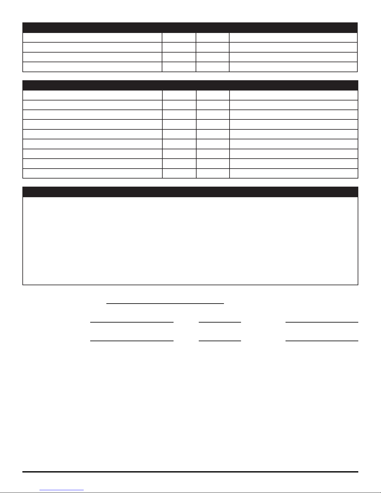
CLEAN AND / OR LUBRICATE IN SPEC REPAIR PROBLEM
SOLUTION TANK CONDITION
SQUEEGEE PIVOT POINTS & KNOBS
SOLUTION FILTER CLEANING
SCRUB DECK LINKAGE
VISUALLY INSPECT IN SPEC REPAIR PROBLEM
DRAIN SAVER
VACUUM FLOATS & SCREENS
VACUUM HOSES
SOLUTION HOSES
BLADE RETAINERS & HARDWARE
SQUEEGEE WHEELS
BRUSH SKIRTS
CASTER CONDITION
DRIVE WHEELS CONDITION
COMMENTS
SERVICING DISTRIBUTOR
TECHNICIAN’S NAME DATE SIGNATURE
CUSTOMER’S NAME DATE SIGNATURE
- 26 - MICROMAG-OP-EN
Page 27

TROUBLE-SHOOTING
PROBLEM CAUSE SOLUTION
NO POWER - NOTHING OPERATES FAULTY POWER SWITCH CONTACT LOCAL SERVICING DEALER
BATTERIES NEED CHARGING SEE CHARGING BATTERIES
FAULTY BATTERIES REPLACE BATTERY
LOOSE BATTERY CABLE TIGHTEN LOOSE CABLE
MAIN CIRCUIT BREAKER TRIPPED WAIT 5 MINUTES FOR AUTO RESET
DETERMINE CAUSE AND CORRECT
SCRUBMOTOR DOES NOT OPERATE GREEN DRIVE BUTTON IS NOT
DEPRESSED
CIRCUIT BREAKER TRIPPED RESET & REDUCE PRESSURE
FAULTY SCRUBDECK MOTOR OR
WIRES
VACUUM MOTOR DOES NOT OPERATE FAULTY VACUUM SWITCH REPLACE SWITCH
CIRCUIT BREAKER TRIPPED RESET & CHECK HOSE
FAULTY VACUUM MOTOR CONTACT LOCAL SERVICING DEALER
CARBON BRUSHES WORN CONTACT LOCAL SERVICING DEALER
INSUFFICIENT SOLUTION FLOW SOLUTION TANK LOW REFILL SOLUTION TANK
FLOW LEVER TURNED DOWN TURN LEVER MORE OPEN
SOLUTION FILTER CLOGGED REMOVE COVER AND CLEAN
SOLUTION LINE CLOGGED REMOVE AND BLOW OUT WITH COM-
SOLUTION VALVE CLOGGED REMOVE COVER AND CLEAN
NO SOLUTION FLOW NO SOLUTION IN TANK FILL SOLUTION TANK
SOLUTION SWITCH IS OFF TURN SOLUTION SWITCH ON
SOLUTION SCREEN CLOGGED REMOVE AND CLEAN SCREEN
FAULTY SOLUTION SOLENOID CONTACT LOCAL SERVICING DEALER
FAULTY SOLUTION SWITCH CONTACT LOCAL SERVICING DEALER
DEPRESS BUTTON ON HANDLEBAR
CONTACT LOCAL SERVICING DEALER
DETERMINE CAUSE AND CORRECT
PRESSED AIR
POOR WATER RECOVERY RECOVERY TANK IS FULL EMPTY RECOVERY TANK
MICROMAG-OP-EN - 27 -
BALL / SCREEN IS CLOGGED REMOVE SCREEN AND CLEAN
VACUUM HOSE IS CLOGGED REMOVE DEBRIS
SQUEEGEE IS CLOGGED REMOVE DEBRIS
SQUEEGE BLADE IS WORN ROTATE OR REPLACE BLADES
FAULTY VACUUM HOSE CONTACT LOCAL SERVICING DEALER
VACUUM MOTOR GASKET TORN CONTACT LOCAL SERVICING DEALER
TANK GASKET FAULTY CONTACT LOCAL SERVICING DEALER
DRAIN PLUG LOOSE TIGHTEN PLUG
VACUUM MOTOR FAULTY CONTACT LOCAL SERVICING DEALER
BATTERY CHARGE LOW CHARGE BATTERIES OVERNIGHT
Page 28

PROBLEM CAUSE SOLUTION
POOR WATER RECOVER ON TURNS WIPERS WORN REPLACE WIPER MATERIAL
WIPERS CHATTER TIGHTEN PIVOT POINTS
SQUEEGEE SWING IS BINDING CONTACT LOCAL SERVICING DEALER
INCORRECT SQUEEGEE SIZE CONTACT LOCAL SERVICING DEALER
TIRES NOISY BEARING DRY GREASE BEARINGS
FAULTY HUBS CONTACT LOCAL SERVICING DEALER
POOR TRACTION EXCESSIVE BRUSH PRESSURE REDUCE PRESSURE WITH SWITCH
WORN DRIVE TIRE REPLACE TIRES
HEAVY SOAP CONCENTRATION CONTACT LOCAL SERVICING DEALER
SHORT RUN TIME BATTERIES RUN DOWN CHARGE BATTERIES TWICE
BATTERIES STILL DOWN CONTACT LOCAL SERVICING DEALER
3
BATTERIES LOW ON WATER FILL WITH DISTILLED WATER TO
ABOVE THE LEAD PLATES
BATTERIES OVER CYCLED CONTACT LOCAL SERVICING DEALER
⁄4''
- 28 - MICROMAG-OP-EN
Page 29

MACHINE SPECS
BODY CONSTRUCTION/DIMENSIONS MICROMAG (PAD ASSIST) MICROMAG (TRACTION)
TANK MATERIAL: POLY (5⁄16'') (.79375 cm) POLY (5⁄16'') (.79375 cm)
CHASSIS CONSTRUCTION:
FRONT CASTERS: (2×) 2.5''×1.38'' [(2×) 6.35×3.5cm] (2×) 2.5''×1.38'' [(2×) 6.35×3.5cm]
REAR WHEELS: (2×) 8''×2'' [(2×) 20 × 5 cm] (2×) 8''×2'' [(2×) 20 × 8 cm]
SIZE (L × W × H): 35''×18''×38'' (89×46×97 cm) 38''×18''×38'' (89×46×97 cm)
SQUEEGEE SIZE: 34'' 34''
WEIGHT (WITHOUT BATTERIES): 115 LB. 152 LB.
WEIGHT (WITH BATTERIES): 298 LB. 317 LB.
SCRUBDECK SYSTEM
DISK BRUSH SIZE: 17-D: (1×) 17'' (43cm)
DISK SCRUBDECK MOTOR: (1×) .75 hp (559 watts) / 200 RPM (1×) .75 hp (559 watts) / 200 RPM
OPTIONAL SCRUBDECK MOTOR: (1×) 1 hp (746 watts) / 200 RPM (1×) 1 hp (746 watts) / 200 RPM
SCRUBDECK DOWN PRESSURE: 0-125 LB (0-68 kg) 0-125 LB (0-68 kg)
EDGE PAD SIZE: N / A 20-EDGE: (1×) 20''×14''
EDGE SCRUBDECK MOTOR: N / A 20-EDGE: (1×) 1.2 hp (895 watts) /
SOLUTION SYSTEM
SOLUTION TANK CAPACITY: 10 GAL (38 liters) 10 GAL (38 liters)
SOLUTION FLOW RATE: 0 - 0.5 GPM (0 - 2 lpm) 0 - 0.5 GPM (0 - 2 lpm)
SOLUTION FILTER: STAINLESS / INLINE STAINLESS / INLINE
1
⁄8'' STEEL (.3175 cm)
20-D: (1×) 20'' (51cm)
1
⁄8'' STEEL (.3175 cm)
17-D: (1×) 17'' (43cm)
20-D: (1×) 20'' (51cm)
2900 RPM
RECOVERY SYSTEM
RECOVERY TANK CAPACITY: 10 GAL 10 GAL
VACUUM POWER: 0.75 HP 0.75 HP
DRAIN HOSE: 1.5'' DIAMETER (4 cm) 1.5'' DIAMETER (4 cm)
VACUUM SPECS (LIFT / AIRFLOW): 70'' / 70 cfm (178 cm / 21cmm) 70'' / 70 cfm (178 cm / 21cmm)
DEMISTING CHAMBER: 1.25 GAL (5 liters) 1.25 GAL (5 liters)
DRAIN SAVER: 30 in
3
(70 cm3) 30 in3 (70 cm3)
BATTERY SYSTEM
SYSTEM VOLTAGE: 24 Volts 24 Volts
STANDARD BATTERY AH RATING: (2×) 85 Ah (2×) 85 Ah
OPTIONAL BATTERY AH RATING: (2×) 130 Ah (2×) 130 Ah
BATTERY RUN TIME (STANDARD): UP TO 3 HRS. UP TO 3 HRS.
CHARGER (AUTOMATIC): 8 AMP 8 AMP
DRIVE SYSTEM
STANDARD DRIVE: PAD ASSIST 0.4 hp (298 watts), All Gear/ Sealed
FORWARD SPEED: N / A 0-230 ft/min (4 mph) (6 kph)
REVERSE SPEED: N / A 0-130 ft/min (2 mph) (3 kph)
PRODUCTIVITY
SCRUBBING WIDTH: 17'', 20'' 17'', 20''
SCRUBBING RATE/HOUR (NORMAL): 18,474 FT/HR 18,474 FT/HR
SCRUBBING RATE/HOUR (MAXIMUM): 20,525 FT/HR 20,525 FT/HR
MICROMAG-OP-EN - 29 -
Page 30
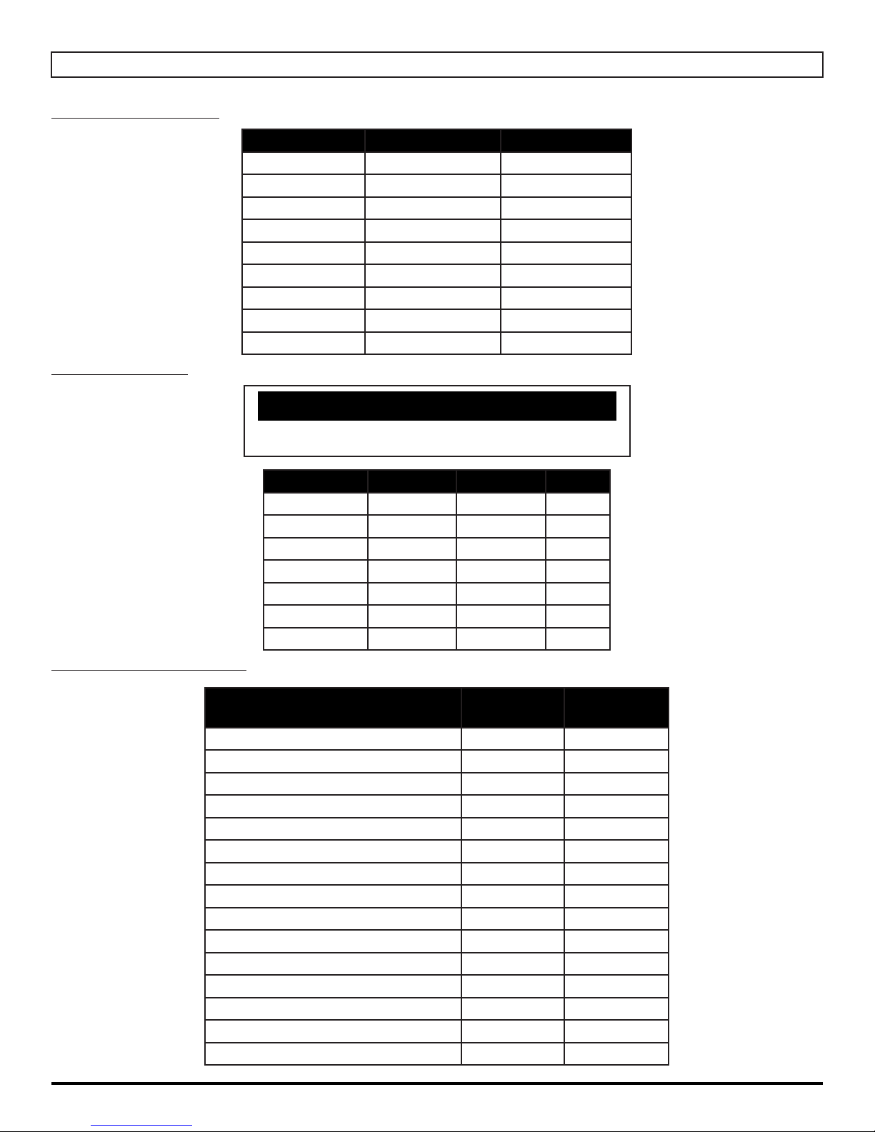
ROUND DISK BRUSHES:
ROUND DISK PADS:
COMMON WEAR PARTS
BRUSHES MODEL 17'' DISK MODEL 20'' DISK
Super Grit
Tough Grit
Midi Grit
Light Grit
Poly (.028)
Nylon (.016)
Tampico
Pad Driver
Diamond Driver
17-421SS 20-421SS
17-421S 20-421S
17-421C 20-421C
17-421PS 20-421PS
17-421P 20-421P
17-421N 20-421N
17-421T 20-421T
17-421D 20-421D
17-421DD 20-421DD
NOTICE
The ## in Disk Column Denotes Desk Pad Size: 17'' or 20''
EDGE PADS AND SCREENS:
DESCRIPTION 20''×14''
White Pad EDGE-4005 N/A
Red Pad EDGE-4004 N/A
Blue Pad EDGE-4003 N/A
Green Pad EDGE-4002 N/A
Black Pad EDGE-4001 N/A
White Driver Pad EDGE-4025 EDGE-4019
60 Grit Sand Screen EDGE-4026 EDGE-4020
80 Grit Sand Screen EDGE-4027 EDGE-4021
100 Grit Sand Screen EDGE-4028 EDGE-4022
120 Grit Sand Screen EDGE-4029 EDGE-4023
150 Grit Sand Screen EDGE-4030 EDGE-4024
20 Grit Sand Paper EDGE-4031 N/A
36 Grit Sand Paper EDGE-4032 N/A
60 Grit Sand Paper EDGE-4033 N/A
80 Grit Sand Paper EDGE-4034 N/A
DISK PADS DISK LEVEL COLOR
Super Black
Black
Brown
Green
Blue
Red
White
##-422BB Very High Black
##-422B High Black
##-422BR High Brown
##-422G Medium Green
##-422BL Moderate Blue
##-422R Moderate Red
##-422W Light White
13''×19''
SCRUBDECK
- 30 - MICROMAG-OP-EN
Page 31
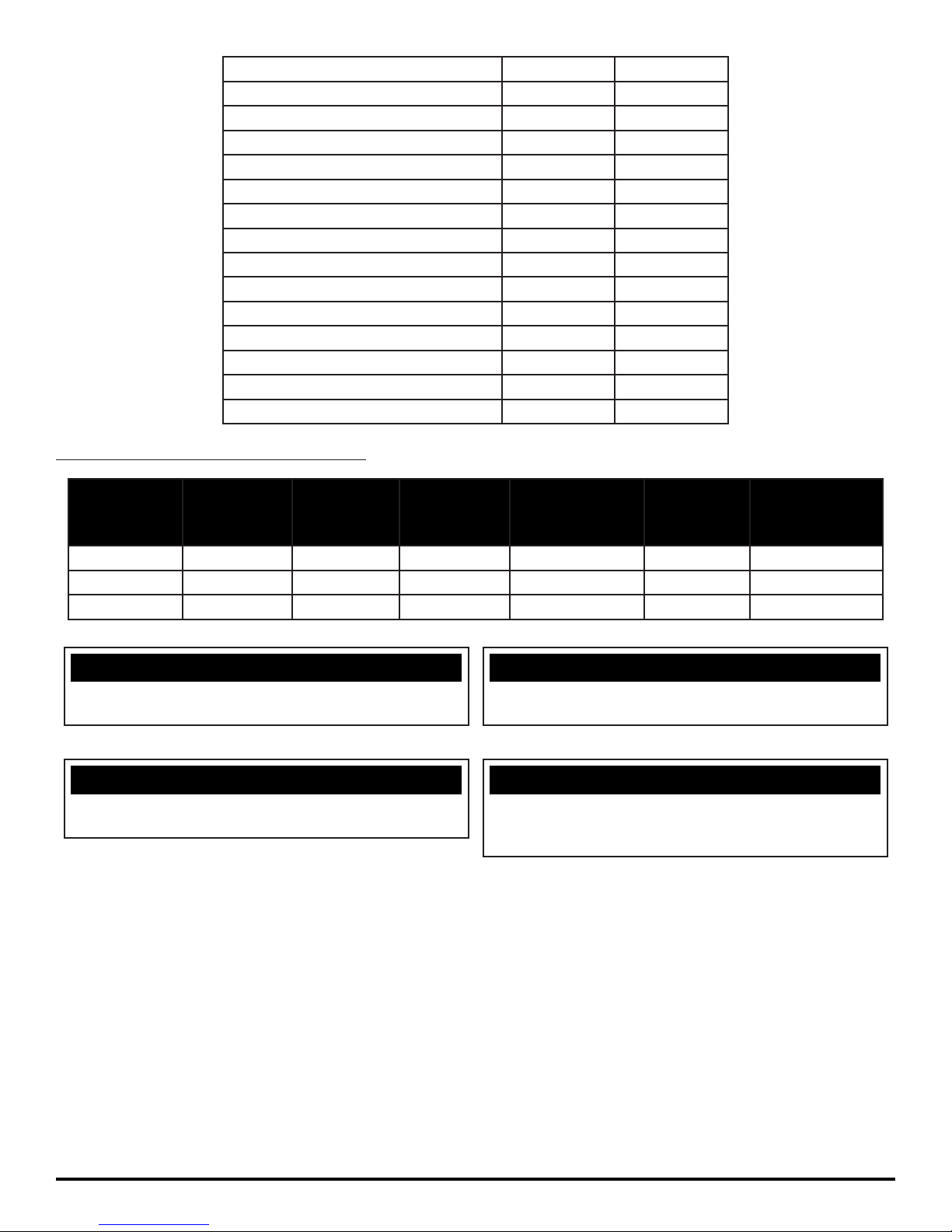
100 Grit Sand Paper EDGE-4035 N/A
100 Grit Diamond Polishing Pad EDGE-4012 N/A
400 Grit Diamond Polishing Pad EDGE-4013 N/A
800 Grit Diamond Polishing Pad EDGE-4014 N/A
1500 Grit Diamond Polishing Pad EDGE-4015 N/A
3000 Grit Diamond Polishing Pad EDGE-4016 N/A
6000 Grit Diamond Polishing Pad EDGE-4070 N/A
Tile/Grout Renovator Pad EDGE-4018 N/A
Microfi ber Pad EDGE-4036 N/A
Abrader Plate N/A EDGE-4011
Dominator HD Strip Pad EDGE-4006 N/A
Maroon ECO Prep Pad EDGE-4007 N/A
Remover Burnishing Pad EDGE-4008 N/A
Porko Burnishing Pad EDGE-4017 N/A
Velcro Pad 300-4023 N/A
SQUEEGEE BLADE KITS & ASSEMBLIES:
SQUEEGEE
SIZE
MODEL 17''
DISK
MODEL 20''
DISK
MODEL 20''
EDGE
GUM RUBBER
BLADE KIT
LINATEX
BLADE KIT
COMPLETE
SQUEEGEE
ASSEMBLIES
26'' Squeegee Optional Optional Optional 130-770G 130-770L 130-7180
30'' Squeegee Optional Optional Optional 150-770G 150-770L 150-7180
34'' Squeegee Standard Standard Standard 180-770G 180-770L 180-7180
NOTICE
Squeegee Blade kits include (1) Rear Blade, (1) Front
Blade, and (2) Backup Wheels with hardware.
NOTICE
Size is stamped into the top of the painted steel
Squeegee body on all Squeegee's.
Squeegee Assemblies (complete) listed above all come
with Linatex Blades.
The 26'' Squeegee is designed for narrow aisles and
may not have the same water control around tight turns
as the large Squeegees.
NOTICE
NOTICE
MICROMAG-OP-EN - 31 -
Page 32
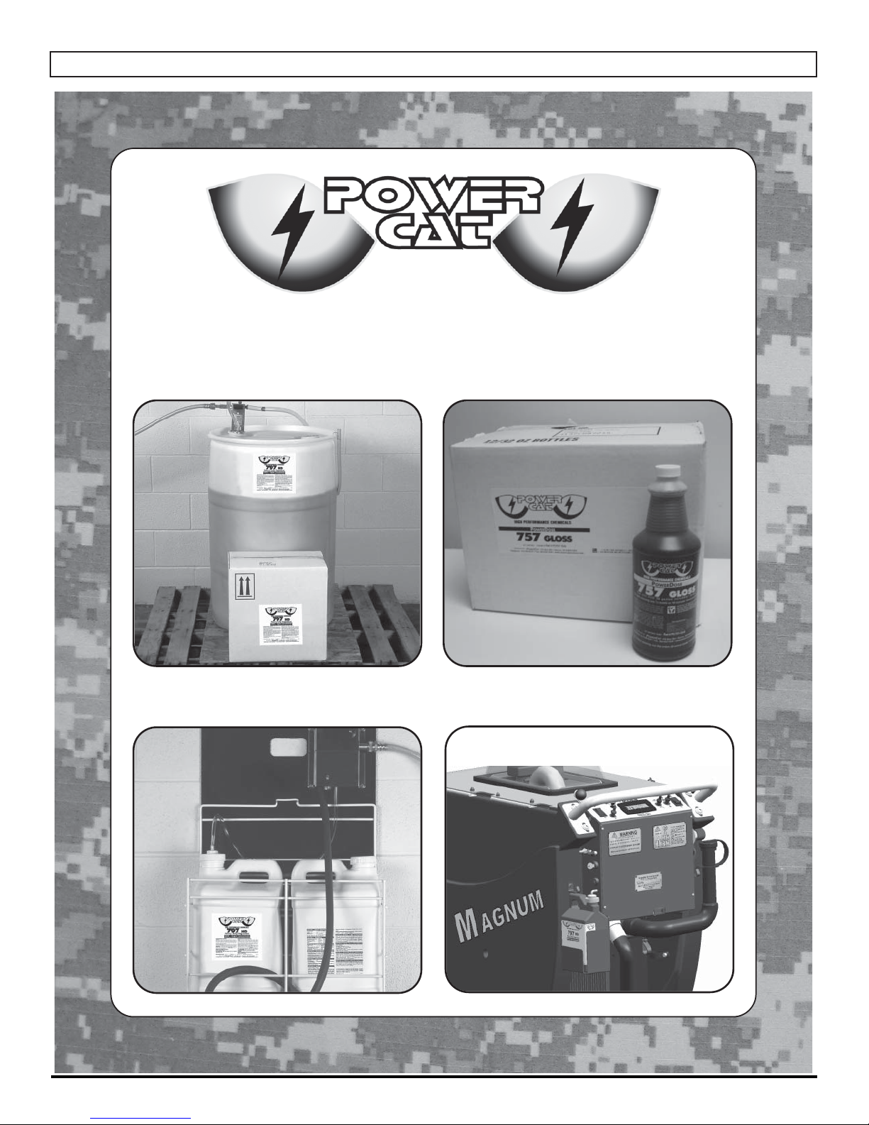
SOAP CHOICES
Industrial • Commercial • Environmentally Safe
TRADITIONAL DRUMS / TOTES
WALL-MOUNTED SUPERCON
DEMO / RENTAL QUARTS
ONBOARD AUTO DISPENSING
- 32 - MICROMAG-OP-EN
Page 33
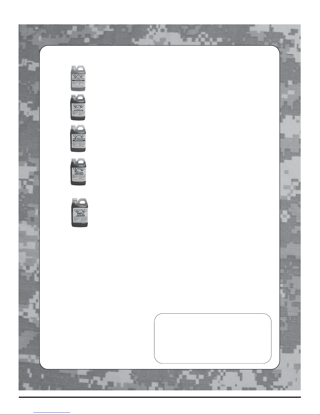
Onboard
Availability
FORMULAS
SUDS
Approved
SUDS
Approved
SUDS
Approved
SUDS
Approved
SUDS
Approved
707 Citrus Green
733 Low pH
755 High Power
757 Gloss
797 HD
An environmentally cleaner that works! It is a solvent free
degreaser that works on oil, carbon, even rubber marks.
Incorporates the latest technology in “Green Cleaning”.
Safe on most surfaces not harmed by water alone.
Low scale formula to prevent alkali buildup in cleaning
equipment, while offer detergent to emulsify oil.
Ideal solvent fortified degreaser. This butyl based
detergent is penetrating, fast acting, and deep cleaning
with built-in corrosion inhibitors. It is our most effective
degreaser.
A high gloss detergent designed to dry to a bright shine.
It is ideal for use on finished surfaces, tile, epoxy, or
enamel. The special formula removes salt residue, scuff
marks and dirt, while leaving no residue behind. The result
is a clean, non-slip surface, ready for immediate use.
The Heavy Duty concentrate is a Super alkaline
detergent, formulated for heavy soil, grease, and thick
buildup. Popular in machine shops, auto and truck repair,
and other facilities with oil, hydraulic fluids and cutting oils.
**Below Sold in bulk concentrate only. Not available as a SuperCon, PowerDose or SUDS product.
727 Pretreat**
744 Tough Stuff**
PowerCat
P.O. Box 503
Racine, WI 53404-0503
Phone: 414-745-9337
Fax: 262-632-1630
www.powercatsolutions.com
Designed to quickly remove tire marks, oil stains and
buildup that has accumulated. This pretreat uses the
powerful cleaning of natural citrus extract and is intended
to be used directly on the floor at 100% concentrate.
Ideal for applications with Hard Water problems. It is safe
to use in pressure washers and automatic scrubbers. The
formulation enhances soil suspension, digests oil and
grease, while supporting extra water conditioner.
Distributed by:
PowerCat, LLC, 2008.
MICROMAG-OP-EN - 33 -
Page 34

STANDARD WARRANTY POLICY
RPS Corporation warrants its machines, parts and accessories to be free of manufacturer’s defects for the periods
specifi ed below. Warranty will be granted at the sole discretion of RPS Corporation and is subject to fi nal claim and
parts review by R.P.S. Corporation and its vendors. This policy is effective January 1, 2014 and is subject to change on
production units at a future date.
COVERAGE, EXCLUSIONS AND LIMITATIONS:
Coverage: All Models Except Floor Machines: 1 Year Parts / 2 Years (1,500 hrs) Motor / 90 Days Labor / No Travel
ZerO3 Wall Mount Units: 6 Months Parts
Parts: 36 months / 1,500 hours on “Power On” hour meter
Labor: 12 months
Travel: 3 months (150 mile maximum)
Poly Tanks: 7 Years (Water must not exceed 135°F/57°C) / 3,000 Hours
OEM Parts: 90 Day New Part Warranty
Validity: Fully completed Machine Delivery Form (online or fax) is on record at RPS and machine is
serviced by Factory Authorized Personnel.
Limitation: Warranty will begin on date of machine installation to end-user or 6 months after shipment from
RPS Corp. to the distributor if unsold at that time.
This warranty includes all parts on the machine except normal wear parts. Some examples of wear parts are:
• EDGE / ORBITZ isolators with evidence of deck damage (images required) or > 1,000 hours.
• Squeegee Blades, Wiper Blades, Skirts and Curtains.
• Caster Wheels, Squeegee Wheels and Bumpers.
• Lights (Strobe, Headlights, or Bulbs).
• Chains and Belts.
• Filters, Screens, and Vacuum Bags.
• Motor Brushes and commutater wear.
• Brooms, Brushes, Pads and Pad Retainers.
• Hoses and Tubing.
• Drive Tires, Pneumatic Wheels and Tubes.
• Rubber Floor Seals and Gaskets.
• Vacuum motors with evidence of moisture or debris intrusion or > 400 hours.
• The Batteries (see below).
• NOT COVERED: Routine maintenance, adjustments or parts damaged from abuse, neglect, improper use of
the machine, or lack of scheduled “daily, weekly, monthly” maintenance in accordance with our published PM
Sheets.
POLY TANKS: 7 Years Coverage against leakage due to manufacturer’s defect in materials or workmanship.
Tank warranty void if water used exceeds 135°F/57°C
NOTE: Freight coverage for 3 Years under the parts section of warranty.
BATTERIES: Warranted through battery manufacturer for One (1) Year (pro-rated) from the date of delivery.
The battery manufacturer approves or denies the warranty coverage after analysis. We rely solely on their
review.
NOTE NOT COVERED: Damage from lack of water, failure to use OEM charger, or non-distilled water. Battery
terminals – Battery terminals and cable connections are covered for 30 days from the shipment of the machine.
(Battery terminals tightness should be inspected every 30 days and performed according to the manufacturer’s
recommendations.)
- 34 - MICROMAG-OP-EN
Page 35

MACHINE INSTALL / WARRANTY REGISTRATION
Installing Dealer: Installed By:
Location: (City, State): Install Date:
End-User Company Name: End-User Contact:
Address: City/State: Zip:
Phone: Fax: Email:
Model: Serial #: Hour Meter:
BUYER’S REPRESENTATIVE HAS RECEIVED INSTRUCTION IN PROPER OPERATION OF THE FOLLOWING CONTROLS AND FEATURES:
SCRUBBERS:
-
- Adjusting controls & operation, Double scrubbing, Squeegee lift delay, High Recovery RED Light, vacuum switch (horn honking) and
vacuum timer
- Shroud and pad/brush removal and installation
- Side Wiper and Curtain adjustment and maintenance for water control
- Solution valve and fi lter operation (removal and cleaning)
- LCD display operation, 4 hour meters (key switch, brush, traction drive, vacuum)
- Tank tilt back feature, only when both tanks are fully drained
- Squeegee hose removal and checking for clogs
Filling solution tank, Solution tank sight tube, Solution drain hose or valve for fl ushing and freezing conditions
- Recovery tank draining & cleaning in APPROVED locations only, Common Squeegee hose clog points, vacuum screen removal and
cleaning, drain saver basket emptied
BURNISHERS
-
- Pad pressure gauge and proper operating range to avoid tripping the circuit breaker
Train and have customer demonstrate proper removal and replacement of burnishing pad
SWEEPERS
- Demonstrate proper removal and replacement of main broom and side brooms
- Method for cleaning the dust fi lter, emptying out the debris hopper and correct installation
- Correct operation of the main broom and side broom levers, and understands to park with brushes in UP position
- Trained on the “Wet-Sweep” bypass door and not to operate through standing water
EDGE / ORBITZ MACHINES
- Customer understands the Grip Face is not warranted against damage from improper use or direct contact with the fl oor
- EDGE / ORBITZ scrubbers must have their isolators & deck hour meter replaced every 1,000 hours of use
ALL MACHINES
- Charging operation and customer understands batteries have limited “cycles” and recharging = 1 cycle
- Seat and steering wheel adjustment
- Customer has read and understands the list of WARNINGS/CAUTIONS in the Operator manual
- Battery and Machine Maintenance Guide posters hung up and reviewed
- Manufacturer’s website is a good source of information (Videos, PM Sheets) and sign up for quarterly newsletters
- Operators and Parts manuals were delivered, reviewed, understood, and confi rmation preventive maintenance is done every 100 hours of
use and recorded on PM Sheets provided online or in manuals
Installed By (print)
Buyers Representative (print) Signature
- Checking for proper battery electrolyte level, electrolyte condition monthly, and check that battery terminals are properly torqued to 10ft/lbs
- Parking Brake works and Park Brake Override functions if installed / Always park on a solid and level surface, NEVER on a movable or
inclinded surface
Signature
Buyer agrees to pay for any repairs, adjustments, or secondary training that manufacturer determines is excluded from the
Complete and Fax form to 1-866-632-6961 or Online at www.rpscorporation.com
MICROMAG-OP-EN - 35 -
warranty.
Page 36

Page 37

Page 38

1711 South Street
Racine, WI 53404
www.rpscorporation.com
www.factorycat.com
www.tomcatequip.com
Tel. US: 800-634-4060
Tel. Int: (011) 262-681-3583
Fax: 866-901-3335
© RPS Corporation 2014
 Loading...