


PLEASE KEEP AND READ CAREFULLY
BEFORE INSTALLING COMPRESSOR
ROYCE AIR COMPRESSOR
415VOLT/3 PHASE
OPERATIONS MANUAL

Table of Contents
Unit Pictures & Descriptions 1
Warning 5
Installation 6
Starting, Run In 7
Maintenance 8
Troubleshooting 9

MODEL - RC130
Page 1
This Model has the same specs as Model RC66.
Control Box Settings
1. Compressor 2 only;
2. Compressor 1 & 2 off;
3. Compressor 1 only;
4. Compressor 1 starts first, then Compressor 2
starts 3 - 4 seconds later.
1
2 3
4
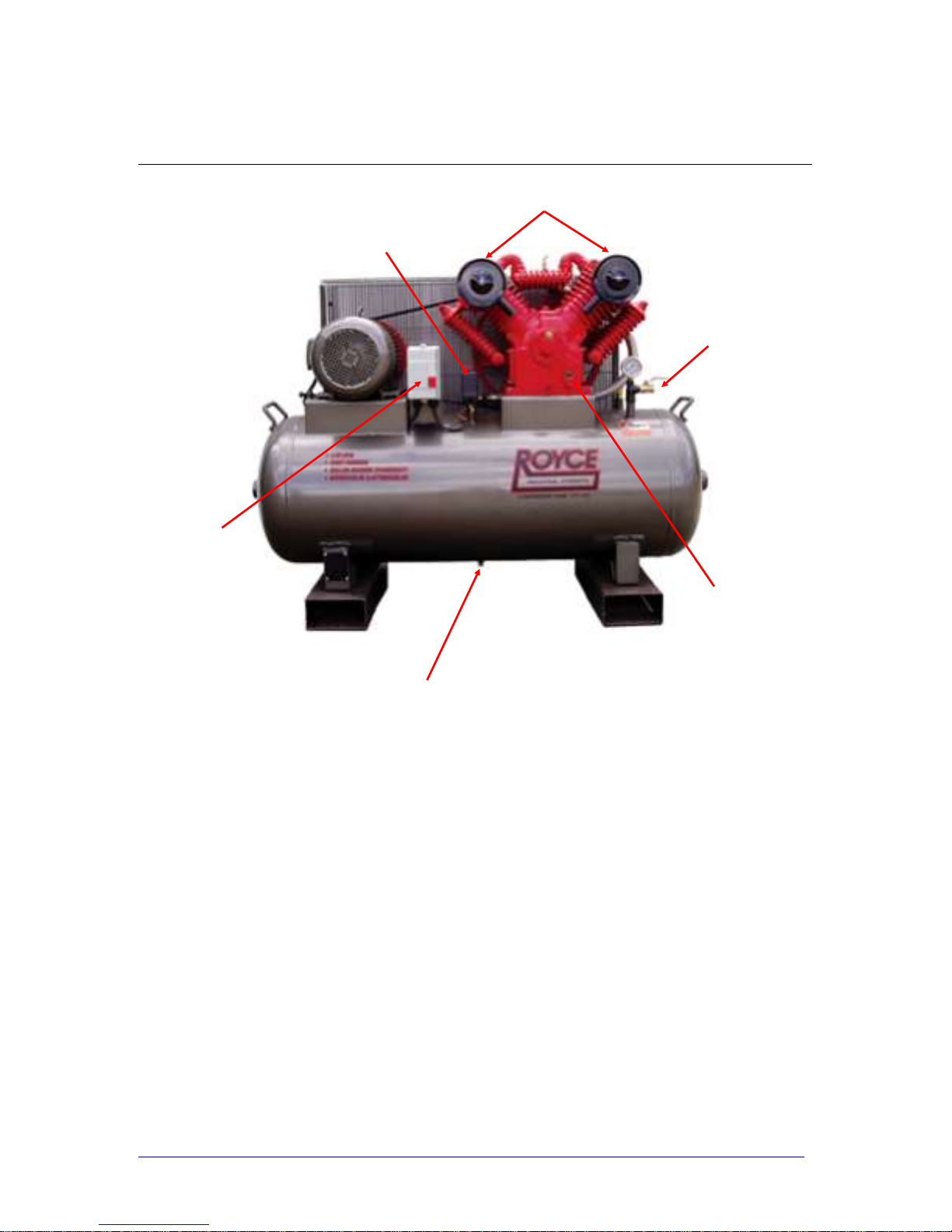
MODEL - RC66
Page 2
1. Air Filters;
2. Tank Outlet;
3. Oil Sight Gauge;
4. Tank Drain Valve;
5. DOL Starter;
6. Pressure Control Switch with On/Off button.
1
2
6
5
4
3

MODEL - RC46
Page 3
1. Air Filters;
2. Tank Outlet;
3. Oil Sight Gauge;
4. Tank Drain Valve;
5. DOL Starter;
6. Pressure Control Switch with On/Off button.
6
2
3
1
5
4

MODEL - RC27
Page 4
1. Air Filters;
2. Tank Outlet;
3. Oil Sight Gauge;
4. Tank Drain Valve;
5. DOL Starter;
6. Pressure Control Switch with On/Off button.
1
6
4
2
5
3

WARNINGS
ELECTRICAL AND MECHANICAL REPAIRS AND/OR
MAINTENANCE SHOULD BE CARRIED OUT BY
QUALIFIED PERSONNEL.
FOR ROUTINE CHECKS ENSURE THAT
ELECTRICAL POWER IS TURNED OFF AT THE
WALL AND AIR PRESSURE IN TANK IS RELEASED.
Page 5

INSTALLATION
Your new Royce Air Compressor has been assembled with
care. It has been test run and fully checked as ‘A-OK’ before
leaving the factory.
On receiving your compressor, check that there is no obvious
transportation damage (filters or fittings broken, belt guard
rubbing on flywheel etc).
Notify your carrier immediately if damage has occurred.
PREPARATION
The compressor should be situated in a clean, dry and well
ventilated position.
It is extremely important that the compressor is level along the
length as well as the width. If base is not level it is possible
that lubrication will not be effective.
The most favored compressor position is along a wall with the
oil sight glass and the pressure gauge facing the operator. To
ensure adequate cooling , place the compressor at least
40cms from wall. Under no circumstances should compressor
be located in hot, unventilated areas, e.g. small garden type
shed in the direct sun with door closed.
Page 6

Page 7
STARTING, RUN-IN
STARTING
Electrical installation should be carried out by a qualified
electrician.
Before starting:-
1. Check that the oil level is in the red circle of the sight
glass.
2. Ensure that belt guard will not rub on the flywheel.
3. Check that all attached air hoses etc are double clamped
and tight.
RUN-IN
1. Open air outlet so that pressure DOES NOT build up.
2. Ensure that pulley is running in direction of the arrow
stamped into top of belt-guard.
3. Run compressor for 30 minutes with nil load (pressure).
4. Close tank valve allowing compressor to build up
pressure and cut off.
5. Ensure that unloader works. You will hear a hiss of air
from under the pressure switch, this hiss will stop after a
few seconds.
6. Check that all nuts and bolts are tight, belt tension is
correct (10mm - 25mm deflection in centre), fittings are
tight and there are no oil leaks.

MAINTENANCE
ENSURE COMPRESSOR IS SWITCHED OFF BEFORE
ATTEMPTING ANY MAINTENANCE.
DAILY MINIMUM - Check oil level and drain tank.
Drain oil and flush crankcase after first 20 hours of operation.
Change oil with 68 Grade Hydraulic Oil
- every 6 months for moderately working units
- every 3 months for hard working units
Check that oil level is to red circle on sight glass.
Check that pressure switch cuts in at approximately 600kPa
(85psi or 6Bar) and cuts out at approximately 800kPa (120psi
or 8Bar). This is the standard pressure working range.
Check belt deflection—10mm to 25mm at centre.
Check that unloader valve is operable (audible hiss when
motor stops).
Check air filters clean or replace when necessary.
Check safety valve and pressure gauge.
Page 8

Page 9
TROUBLESHOOTING
SYMPTOM Motor won’t start;
Running slow;
Getting hot.
POSSIBLE CAUSE Fault in wiring;
Voltage drop;
Faulty unloader;
Faulty pressure switch;
Faulty starter;
Faulty motor.
SYMPTOM Compressor flywheel will not
turn.
POSSIBLE CAUSE Pump seized;
Low oil;
Foreign obstruction.
SYMPTOM Vibration
POSSIBLE CAUSE Uneven location;
Loose mounting bolts;
Internal pump damage;
Wear in pump;
Belts worn or loose.

Page 10
TROUBLESHOOTING
SYMPTOM Discharge capacity decreased
POSSIBLE CAUSE Motor running too slow;
Belts slipping;
Air filters blocked;
Air leaks;
Exhaust line leak;
Damaged head / valve gasket;
Valve / valve seat worn;
Piston ring / cylinder worn.
SYMPTOM Excessive oil consumption
POSSIBLE CAUSE Oil leaks;
Crankcase breather blocked;
Oil level too high;
Incorrect oil type / grade;
Piston ring / cylinder worn.
SYMPTOM Pump getting hot
POSSIBLE CAUSE Insufficient ventilation;
Air discharge restricted;
Work cycle too high;
Low oil level;
Internal pump damage.

NOTES

Phone: 07 3205 2599
Fax: 07 3205 2338
E-mail: sales@compressorcare.com.au
362 Leitchs Road
Strathpine Qld 4500
Compressor Care Pty Ltd
 Loading...