

Page 1
INSTALLATION INSTRUCTIONS
Gas Changeover Kit
Natural to Regulated LP/Propane (Kit #11K48)
For A802, 80G2, A952, A962 & 95G2 Units
This manual must be left with the homeowner for future reference.
This is a safety alert symbol and should never be ignored. When you see this symbol on labels or in
manuals, be alert to the potential for personal injury or death.
WARNING
In the U.S., this conversion kit is to be installed
by a licensed professional service technician (or
equivalent) or other qualied agency in accordance
with the manufacturer’s instructions and all codes and
requirements of the authority having jurisdiction. If the
information in these instructions is not followed exactly, a
re, an explosion, or production of carbon monoxide may
result, causing property damage, personal injury or loss
of life. The qualied agency is responsible for the proper
installation of the kit. The installation is not proper and
complete until the operation of the converted furnace
is checked as specied in the furnace manufacturer’s
instructions supplied with the kit.
Application
Use natural to LP gas conversion kit 11K48 to convert
A802, 80G2, A952, A962 and 95G2 gas furnaces from
natural gas to regulated LP/Propane.
Installation
CAUTION
As with any mechanical equipment, personal injury can
result from contact with sharp sheet metal edges. Be
careful when you handle this equipment.
Shipping and Packing List
Package 1 of 1 contains the following:
2 - LP/Propane regulator springs (77W89)
12 -Main burner orices (0.034)
gas supply to the furnace, then turn off the electrical
power at the unit disconnect switch.
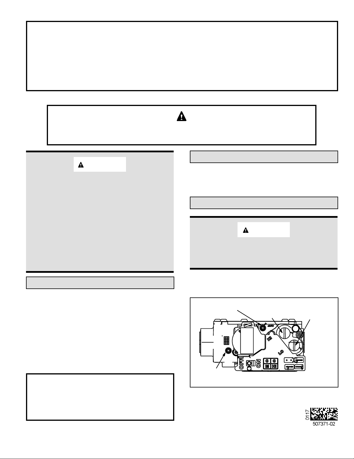
MANIFOLD
PRESSURE
POST
HIGH FIRE
ADJUSTMENT
SCREW
(under cap)
LOW FIRE
ADJUSTMENT
SCREW
(under cap)
1 - Gas converter sticker
1 - Nameplate conversion sticker
1 - Low gas inlet pressure switch
1 - Gas valve inlet brass tting
1 - Wire harness
1. Set the thermostat to the lowest setting. Shut off the
INLET
PRESSURE POST
Manufactured By
Allied Air Enterprises LLC
A Lennox International, Inc. Company
215 Metropolitan Drive
West Columbia, SC 29170
GAS VALVE SHOWN IN OFF POSITION
Figure 1. White Rogers Gas Valve
Save these instructions for future reference
507371-02 Issue 1706 Page 1 of 5
Page 2
2. Remove the access panel. Move the automatic gas
valve switch to OFF. See Figure 1.
3. Disconnect the gas supply from the gas valve.
Disconnect the wiring harness at the gas valve.
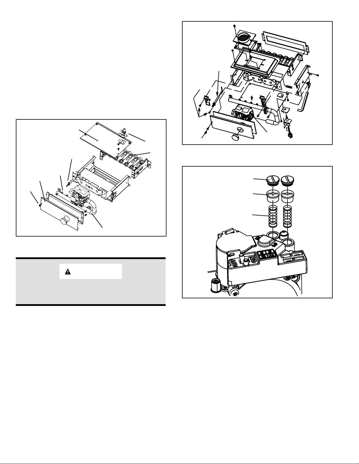
4. Remove the screw that secures the burner box front
cover and remove front cover. See Figure 2 or Figure
3.
5. Remove the four manifold securing screws. Remove
the manifold/gas valve assembly. Replace the main
burner orices with the provided orices. Torque to
approximately 35 in-lbs. See Figure 2 or Figure 3 .
NOTE: LP/Propane orices will be labeled (LP .034).
Burner
Box Top
Cover
Ignitor
Burners
Sensor
Sensor
Manifold
Securing
Screw
Screw
Gas
Orifices
Gas Valve
Figure 3. A952 & 95G2 Burner Box
Gas
Valve
Regulator
Vent
Hose
Ignitor
Burner Box
Front Cover
Screw
Orifice
Manifold
Figure 2. A802 & 80G2 Burner Box
IMPORTANT
DO NOT use pipe dope or any pipe sealant on gas orice
threads.
6. Gas Valve Conversion
a. Remove both high re and low re springs from
the gas valve. See Figure 4.
b. Replace both high re and low re springs with the
provided LP springs color-coded white.
c. Install the high re adjustment screw and adjust
approximately 12 turns.
d. Install the low re adjustment screw and adjust
approximately 8 turns.
e. Install both regulator screw covers.
High
Regulator
Cover Screw
Plastic Regulator
Adjustment Screw
Regulator Spring
Low
Figure 4.
7. A802 and 80G2 units with Nox inserts being converted
from natural to LP/Propane.
a. Remove the burner box assembly from the
vestibule panel.
b. Remove the screws which secures each of the
NOx inserts to the clamshell. Remove the NOx
inserts and reinstall the screws. See Figure 5.
c. Re-install burner box assembly.
507371-02Issue 1706Page 2 of 5
Page 3
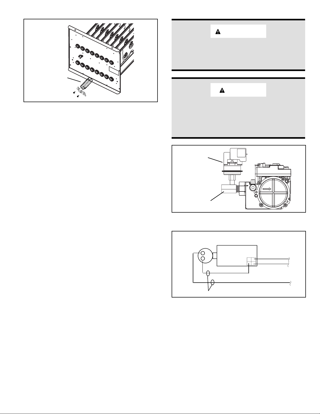
NOx Insert
IMPORTANT
Carefully check all piping connection for gas leaks. DO
NOT use matches, candles, open ames or other means
of ignition to check for gas leaks. Use a soap solution or
other preferred means.
Re-install
Screws
Figure 5. NOx Inserts
8. Re-install the manifold/valve assembly.
9. Thread provided brass tting to gas valve inlet until
hand tight. Using properly sized wrench, tighten tting
2 to 3 full turns being careful to position the side port to
allow clearance for the pressure switch and harness.
See Figure 6.
NOTE: Never use channel lock pliers or a pipe wrench
on the brass tting.
NOTE: Some installations may require the pressure
switch and tting assembly to be positioned differently
than shown in Figure 6.
10. Thread the gas supply to the brass tting until hand
tight. Using properly sized wrench to support brass
tting, tighten supply line into tting 2 to 3 full turns to
achieve leak free joint.
NOTE: Do not over tighten. (Maximum 3 full turns past
hand tight for ½” NPT per ASME B1.20.1-2013)
11. Thread pressure switch to brass tting 2 to 3 turns
past hand tight, then wire as shown in Figure 7.
12. Restore the electrical power to the unit.
13. Inspect all sides of assembly. Turn on gas supply.
Immediately check the entire tting surface and
assembly joints for gas leaks.
14. Afx nameplate conversion sticker next to unit
nameplate.
15. Complete the information required on the gas converter
sticker: date, name, and address. Afx sticker to the
exterior of the unit in a visible area.
16. Follow the steps given in the start-up and adjustment
section.
CAUTION
Some soaps used for leak detection are corrosive to
certain metals. Carefully rinse piping thoroughly after
leak test has been completed. Do not use matches,
candles, ame or other sources of ignition to check for
gas leaks.
Low Inlet Pressure
Switch
Brass Fitting
Figure 6. Gas Valve with Low Inlet Pressure Switch
LOW INLET
PRESSURE
SWITCH
C
NO
PROVIDED HARNESS WIRES
Figure 7. Low Inlet Pressure Switch Wiring
Point-to-Point Wiring Diagram
GAS VALV E
WHITE
ORANGE
YELLOW
BROWN
ORANGE
507371-02 Issue 1706 Page 3 of 5
Page 4

Start-Up & Adjustment
BEFORE PLACING THE UNIT INTO OPERATION
Smell all around the appliance area for gas. Be sure to
smell next to the oor because LP/Propane gas is heavier
than air and will settle on the oor.
Use only your hand to move the gas control switch. Never
use tools. If the switch will not move by hand, do not try to
repair it. Force or attempted repair may result in a re or
explosion.
A - Placing the Unit into Operation
See Table 1 for supply line pressure. Following the supply
pressure check, turn off unit, remove manometer and
tighten post hex screw.
B - Measuring & Adjusting the Manifold Pressure
A952 & 95G2 Models
A manifold pressure post located on the gas valve provides
access to the manifold pressure. See Figure 1. Back out
the 3/32 hex screw one turn, connect a piece of 5/16
tubing and connect to a manometer to measure manifold
pressure. To correctly measure manifold pressure, the
differential pressure between the positive gas manifold
and the negative burner box must be considered. Furnace
should operate at least 5 minutes before checking manifold
pressure.
IMPORTANT
Follow the lighting instructions provided on the unit.
If lighting instructions are not available, refer to the
following section.
Units are equipped with a two-stage integrated ignition
system. The integrated ignition control automatically lights
the burners each time the thermostat calls for heat.
1. STOP! Read the safety information at the beginning
of this section.
2. Set the thermostat to its lowest setting.
3. Turn off all electrical power to the furnace.
4. Do not try to light the burners by hand.
5. Remove the unit access panel.
6. Move the switch on the gas valve to OFF. Do not force
the switch. See Figure 1.
7. Wait ve (5) minutes for any gas to clear out. If you
then smell gas, STOP! Immediately call your gas
supplier from a neighbor’s phone. Follow the gas
supplier’s instructions. If you do not smell gas, go to
the next step.
8. Move the switch on the gas valve to ON.
9. Replace the unit compartment access panel.
10. Turn on all electrical power to the unit.
11. Set the thermostat to desired setting.
12. If the furnace will not operate, see section E- “Turning
Gas Off to the Unit” and call the gas supplier.
Gas Pressure Measurement
A - Supply Pressure Measurement
An inlet pressure post located on the gas valve provides
access to the supply pressure. See Figure 1. Back out the
3/32 hex screw one turn, connect a piece of 5/16 tubing
and connect to a manometer to measure supply pressure.
Check the unit on high re. On multiple unit installations,
check the unit separately and with the other units operating.
1. Connect the test gauge positive side “+“ to manifold
pressure tap on gas valve as noted above.
2. Tee into the gas valve regulator vent hose and connect
to test gauge negative “-”.
3. Ignite unit on low re and let run for 5 minutes to allow
for steady state conditions.
4. After allowing unit to stabilize for 5 minutes, record
low re manifold pressure and compare to value given
in Table 1. If necessary, make adjustment. Figure 1
shows location of low re adjustment screw.
5. Repeat on high re and compare to value given in
Table 1. If necessary, make adjustment. Figure 1
shows location of high re adjustment screw.
A802 & 80G2 Models
A manifold pressure post located on the gas valve provides
access to the manifold pressure. See Figure 1. Back out
the 3/32 hex screw one turn, connect a piece of 5/16
tubing and connect to a manometer to measure manifold
pressure.
1. Connect test gauge to manifold pressure post (Figure
1) on gas valve.
2. Ignite unit on low re and let run for 5 minutes to allow
for steady state conditions.
3. After allowing unit to stabilize for 5 minutes, record
manifold pressure and compare to value given in
Table 1.
4. If necessary, make adjustments. Figure 1 shows
location of high re and low re adjustment screws.
5. Repeat steps 2, 3 and 4 on high re. See values in
Table 1.
Manifold Pressure in w.g. Gas Line Pressure in w.g.
Low Fire High Fire Minimum Maximum
4.9 10.0 11.0 13.0
Table 1. Manifold and Gas Line Pressure
507371-02Issue 1706Page 4 of 5
Page 5

C - Gas Flow (Approximate)
NOTE: To obtain accurate reading, shut off all other gas
appliances connected to meter.
Furnace should operate at least 5 minutes before checking
gas ow. Determine time in seconds for two revolutions of
gas through the meter. (Two revolutions assures a more
accurate time.) Divide by two and compare to time in
Table 2. If manifold pressure matches Table 1 and rate is
incorrect, check gas orices for proper size and restriction.
Remove temporary gas meter if installed.
% for LP
CO
Unit Capacity
-045 6.6 - 7.6 9.1 - 10.1
-070 6.5 - 7.5 8.6 - 9.6
-090 6.9 - 7.9 9.1 - 10.1
-110 7.3 - 8.3 9.5 - 10.5
The carbon monoxide reading should not exceed 100 ppm.
Low Fire High Fire
2
Table 4. A952 & 95G2 Downow Furnaces
Seconds for One Revolution
Unit Capacity
1 cu ft Dial 2 cu ft Dial
-045 200 400
-070 136 272
-090 102 204
-110 82 164
-135 68 136
2500 btu/cu ft
LP
Table 2. Gas Meter Clocking Chart
D- Proper Combustion
Furnace should operate minimum 15 minutes with correct
manifold pressure and gas ow rate before checking
combustion. Take combustion sample beyond the ue
outlet. See Table 3 through Table 5 .
NOTE: Shut unit off and remove manometer as soon as
supply line pressure, manifold pressure and combustion
sample have been obtained. Take care to replace pressure
tap plug.
All Models Firing Rate CO2% for Nat CO2% for LP
Upow/
Horizontal
Downow
The carbon monoxide reading should not exceed 100 ppm.
High Fire 6.8 - 7.4 7.5 - 9.0
Low Fire 4.2 - 5.7 5.0 - 6.0
High Fire 6.0 - 7.4 6.9 - 8.4
Low Fire 4.8 - 6.0 5.7 - 7.0
Table 5. A802 & 80G2
E - Turning Off Gas to the Unit
1. Set the thermostat to its lowest setting.
2. Turn off all the electrical power to the unit.
3. Remove the unit access panel.
4. Move the switch on the gas valve to OFF. Do not force
the switch.
% for LP
CO
Unit Capacity
-045 6.4 - 7.4 8.8 - 9.8
-070 6.3 - 7.3 8.7 - 9.8
-090 6.8 - 7.8 8.9 - 9.9
-110 7.1 - 8.1 9.3 - 10.3
-135 7.1 - 8.2 9.1 - 10.1
The carbon monoxide reading should not exceed 100 ppm.
Low Fire High Fire
2
Table 3. A952 & 95G2 Upow / Horizontal Furnaces
507371-02 Issue 1706 Page 5 of 5
 Loading...