

Page 1

RSA-1500L User Manual
RSA-1500L User Manual
Version 1.2
2008/01/24
This document contains information highly confidential to RoyalTek Company
LTD (RoyalTek). It is provided for the sole purpose of the business discussions
between supplier and RoyalTek and is covered under the terms of the
applicable Non-Disclosure Agreements. Disclosure of this information to other
parties is prohibited without the written consent of RoyalTek.
Prepared by RoyalTek Company LTD.
1071, Chung Cheng Rd., Suite 9F-1
Tao Yuan City, Taiwan
Tel: 886-3-3569666
Fax: 886-3-3580050
http://www.royaltek.com/contact
Page 2

RSA-1500L User Manual
Figure List ................................................................................................................................ II
Table List ................................................................................................................................. III
1 Introduction ..................................................................................................................... 4
1.1 Product applications ..................................................................................... 4
1.2 Product Picture .............................................................................................. 5
1.3 RSA-1500L System Block Diagram ............................................................. 5
1.4 RSA-1500L Technique Specification ........................................................... 6
1.5 Application Circuit......................................................................................... 8
1.6 Mechanical Layout ........................................................................................ 9
1.7 Hardware interface ...................................................................................... 10
2 Software Interface ......................................................................................................... 12
2.1 NMEA V3.0 Protocol .................................................................................... 12
2.1.1 GGA-Global Positioning System Fixed Data ................................... 12
2.1.2 GLL-Geographic Position –Latitude/Longitude............................... 13
2.1.3 GSA-GNSS DOP and Active Satellites .............................................. 14
2.1.4 GSV-GNSS Satellites in View............................................................. 14
2.1.5 RMC-Recommended Minimum Specific GNSS Data....................... 15
2.1.6 VTG-Course Over Ground and Ground Speed ................................ 16
3 Package.......................................................................................................................... 17
3.1 Package Specification................................................................................. 17
4 Contact Information Section........................................................................................ 17
5 Revision History............................................................................................................ 17
I
Page 3

II
RSA-1500L User Manual
Figure List
Figure 1-1 RSA-1500L Front View......................................................................... 5
Figure 1-2 RSA-1500L Bottom View ..................................................................... 5
Figure 1-3 System Block Diagram ........................................................................ 5
Figure 1-4 Application Circuit Reference............................................................. 8
Figure 1-5 Mechanical Layout ............................................................................... 9
Figure 1-6 Hardware Interface............................................................................. 10
Figure 3-1 Package Specifications ..................................................................... 17
Page 4

RSA-1500L User Manual
Table List
Table 1-1 Technical Specifications ....................................................................... 6
Table 1-2 Definition of Pin assignment .............................................................. 10
Table 2-1 NMEA-0183 Output Messages ............................................................ 12
Table 2-2 GGA Data Format ................................................................................. 12
Table 2-3 Position Fix Indicators ........................................................................ 13
Table 2-4 GLL Data Format .................................................................................. 13
Table 2-5 GSA Data Format ................................................................................. 14
Table 2-6 Mode 1................................................................................................... 14
Table 2-7 Mode 2................................................................................................... 14
Table 2-8 GSV Data Format ................................................................................. 15
Table 2-9 RMC Data Format................................................................................. 15
Table 2-10 VTG Data Format................................................................................ 16
III
Page 5

RSA-1500L User Manual
1 Introduction
RoyalTek RSA-1500L low power and small form factor board is the newest generation
of RoyalTek smart antenna GPS module. The smart antenna GPS module is powered
by SiRF Star III technology and RoyalTek proprietary navigation algorithm that
providing you more stable navigation data. Parallel design is the major new feature of
RSA-1500L.
The smallest form factor and parallel design is the best choice to be embedded in a
portable device and receiver like PND, mobile phone, car holder, personal locator,
digital camera and vehicle locator. The excellent sensitivity of RSA-1500L gets the
great performance when going though the urban canyon and foliage
Product Features
20 parallel channels
Extreme fast TTFF at low signal level
Operable from 3.3V/48mA continuous mode.
Wire to board connector
TCXO design
0.1 second reacquisition time
Small form factor with embedded SiRF Star III single chip technology.
NMEA-0183 compliant protocol/custom protocol.
4 Mbits Flash Memory
Enhanced algorithm for navigation stability
Excellent sensitive for urban canyon and foliage environments.
SBAS (WAAS, EGNOS and MSAS) support
Auto recovery while RTC crashes
Trickle power supported
1.1 Product applications
Automotive navigation
Personal positioning and navigation
Marine navigation
Timing application
4
Page 6
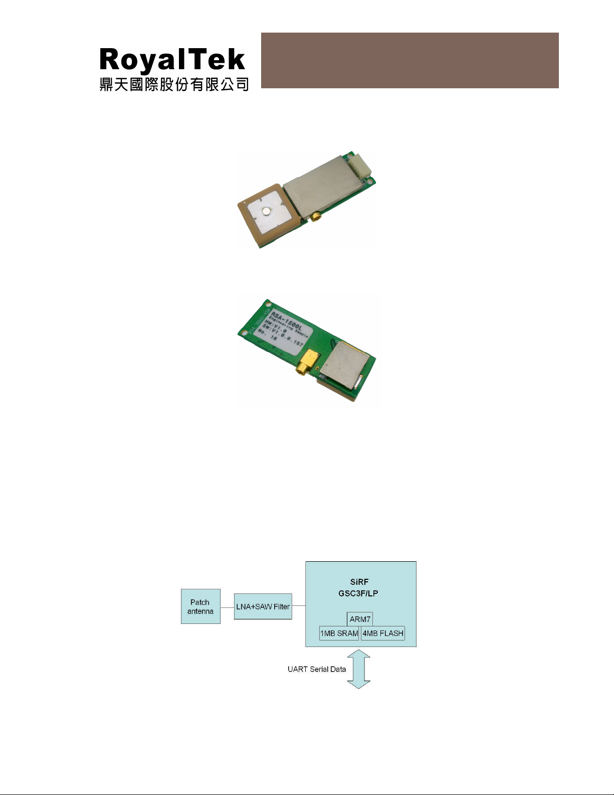
1.2 Product Picture
RSA-1500L
RSA-1500L User Manual
Figure 1-1 RSA-1500L Front View
Figure 1-2 RSA-1500L Bottom View
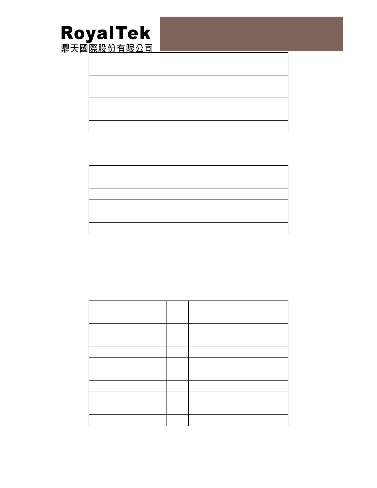
1.3 RSA-1500L System Block Diagram
System block diagram description :
a. External antenna.
b. 4 Mega bits flash memory
c. 6 pin I/O pin
Figure 1-3 System Block Diagram
5
Page 7

RSA-1500L User Manual
1.4 RSA-1500L Technique Specification
Table 1-1 Technical Specifications
Impedance::::50ΩΩΩΩ
No Function Specification
GPS receiver
1 Chipset
2 Frequency L1 1575.42MHz.
3 Code C.A. Code.
4 Channels 20 parallel
5 Chipset Sensitivity -159dBm.
6 Cold start 35 sec @ open sky
7 Warm start 35 sec @ open sky
8 Hot start 1 sec @ open sky
9 Reacquisition 0.1sec typical
10 Position accuracy 10meters at 2D RMS.
11 Maximum altitude 18000 m
12 Maximum velocity 514 m/s
13 Trickle power mode 40mA@Average
14 Update rate Continuous operation: 1Hz
15 Testability It shall be able to be tested by SiRF test IV and single channel
SiRF Star III, GSC3f/LP
(Digital, RF in a single package)
simulator.
16 Protocol setup It shall store the protocol setup in the SRAM memory.
17 DGPS 1.WAAS, EGNOS
Interface
18 LNA 25dB Gain. (Typical)
19 I/O Pin 6pin
Mechanical requirements
20 Weight 8.3g Typ.
Power consumption
21 Vcc DC +3.3 V±5%
22 Current
GPS :
Avg Acquisition <50mA@3.3V without ext.Antenna
Avg Tracking <48mA@3.3V without ext.Antenna
Environment
6
Page 8

RSA-1500L User Manual
23
Operating
temperature
24
Storage temperature -40 ~ 85℃
25
Humidity
-25 ~ 85℃
≦95%
MMCX edge mount Jack Receptacle specification (External Antenna)
Impedance 50ohm
Frequency range 0~6GHz
V.S.W.R 1.2max
Working voltage 175Vrms max
Durability 500 mating
External Antenna spec.
DC supply
DC current 20mA max.
Input return Loss
Output return Loss
2.85V±2%
≦-10dB
≦-10dB
Gain
25 dB typical
7
Page 9

1.5 Application Circuit
RSA-1500L User Manual
Note:
Figure 1-4 Application Circuit Reference
(1) Ground Planes:
This pin2 should be connect to ground.
(2) Serial Interface:
(Ⅰ) The TXA pin is recommended to connect to serial resistance(220Ω)
and pull up (10KΩ). It can increase the stability of serial data. (Default
NMEA)
(Ⅱ) The RXA pin is recommended to connect to serial resistance(220Ω)
and pull up (10KΩ). It can increase the stability of serial data. (Default
NMEA)
(3) Backup Battery:
When module is working, must to supply VCC pin(Pin1) and VBATT
pin(Pin6) power at the same time.
It’s recommended to connect a backup battery to VBATT pin.
In order to enable the warm start and hot start features of the GPS receiver.
If you use backup battery, should be add a bypassing capacitor (10uF) at
VBATT pin. It can reduce noise and increase the stability.
8
Page 10

RSA-1500L User Manual
(4) Power:
Connect VCC pin to DC 3.3V. The power supply must add bypass
capacitor(10uF and 1uF).It can reduce the Noise from power supply and
increase power stability.
(5) GPIO:
The GPIOs function are for customer used.
If no use GPIO function, it don’t connect anything.
1.6 Mechanical Layout
Figure 1-5 Mechanical Layout
9
Page 11

10
+
+
1.7 Hardware interface
RSA-1500L User Manual
Figure 1-6 Hardware Interface
Table 1-2 Definition of Pin assignment
Pin Defined
Pin Signal Name I/O Description Characteristics
1 VCC I DC Supply
Voltage input
2 GND G Ground Reference Ground
3 TXA O Serial port A
4 RXA I Serial port A
5 GPIO-1 I/O General
purpose I/O
6 VBATT I Backup voltage
supply
DC +3.3V±5%
10uACurrent
≤
VVVVV
VVVVV
86.00.3V- 0.215.3 ≤≤≥≥
VVVVV
86.00.3V- 0.215.3 ≤≤≥≥
VVVVV
71.0 14.285.2 ≤≥≥
7.0 38.285.2 ≤≥≥
OLOH
ILIH
ILIH
OLOH
3.6V~2.5 DC
Page 12

RSA-1500L User Manual
Definition of Pin assignment
VCC(+3.3V DC power Input)
This is the DC power supply input pin for GPS system. It provides voltage to
module.
GND
GND provides the reference ground.
TXA
This is the main transmitting channel and is used to output navigation and
measurement data to SiRFdemo or user written software
RXA
This is the main receiver channel and is used to receive software commands to
the board from SIRFdemo software or from user written software.
VBATT (Backup battery )
When module is working, must to supply VCC pin(Pin1) and VBATT pin(Pin6)
power at the same time.
This is the battery backup input that powers the SRAM and RTC when main
power is removed. Typical current draw is 10uA.
The supply voltage should be between 2.5V and 3.6V.
GPIO Functions
Several I/Os are connected to the digital interface connector for custom
applications.
11
Page 13

12
RSA-1500L User Manual
2 Software Interface
2.1 NMEA V3.0 Protocol
Its output signal level is TTL: 4800 bps (default), 8 bit data, 1 stop bit and no parity. It supports
the following NMEA-0183
Messages: GGA, GLL, GSA, GSV, RMC and VTG.
NMEA Output Messages: the Engine board outputs the following messages as shown in Table
2-1:
Table 2-1 NMEA-0183 Output Messages
NMEA Record Description
GGA Global positioning system fixed data
GLL Geographic position – latitude / longitude
GSA GNSS DOP and active satellites
GSV GNSS satellites in view
RMC Recommended minimum specific GNSS data
VTG Course over ground and ground speed
2.1.1 GGA-Global Positioning System Fixed Data
Table 2-2 contains the values of the following example:
$GPGGA, 161229.487, 3723.2475, N, 12158.3416, W, 1, 07, 1.0, 9.0, M, , , ,0000*18
Table 2-2 GGA Data Format
Name Example Units Description
Message ID $GPGGA
UTC Position 161229.487
Latitude 3723.2475
N/S Indicator N N=north or S=south
GGA protocol header
hhmmss.sss
ddmm.mmmm
Longitude 12158.3416
E/W Indicator W E=east or W=west
Position Fix Indicator 1 See Table 2-1
Satellites Used 07 Range 0 to 12
HDOP 1.0 Horizontal Dilution of Precision
MSL Altitude 9.0 meters
Units M meters
Dddmm.mmmm
Page 14
13
RSA-1500L User Manual
Geoid Separation meters
Units M meters
Age of Diff. Corr. second Null fields when DGPS is not
used
Diff. Ref. Station ID 0000
Checksum *18
<CR><LF>
End of message termination
Table 2-3 Position Fix Indicators
Value Description
0 Fix not available or invalid
1 GPS SPS Mode, fix valid
2 Differential GPS, SPS Mode, fix valid
3-5 Not Supported GPS PPS Mode, fix valid
6 Dead Reckoning Mode, fix valid
2.1.2 GLL-Geographic Position –Latitude/Longitude
Table 2-4 contains the values of the following
Example: $GPGLL, 3723.2475, N, 12158.3416, W, 161229.487, A*2C
Table 2-4 GLL Data Format
Name Example Units
Message ID $GPGLL GLL protocol header
Latitude 3723.2475 ddmm.mmmm
N/S Indicator N N=north or S=south
Longitude 12158.3416 Dddmm.mmmm
E/W Indicator W E=east or W=west
UTC Position 161229.487 hhmmss.ss
Status A A=data valid or V=data not valid
Mode A A=Autonomous, D=DGPS, E=DR
Checksum *2C
<CR><LF>
End of message termination
Description
Page 15

14
RSA-1500L User Manual
2.1.3 GSA-GNSS DOP and Active Satellites
Table 2-5 contains the values of the following example:
$GPGSA, A, 3, 07, 02, 26, 27, 09, 04, 15, , , , , , 1.8,1.0,1.5*33
Table 2-5 GSA Data Format
Name Example Units
Message ID $GPGSA GSA protocol header
Mode 1 A See Table 4-2
Mode 2 3 See Table 4-1
Satellite Used 07 Sv on Channel 1
Satellite Used 02 Sv on Channel 2
…. ….
Satellite Used Sv on Channel 12
PDOP 1.8 Position Dilution of Precision
HDOP 1.0 Horizontal Dilution of Precision
VDOP 1.5 Vertical Dilution of Precision
Checksum *33
<CR><LF>
End of message termination
Description
Table 2-6 Mode 1
Value Description
1 Fix not available
2 2D
3 3D
Table 2-7 Mode 2
Value Description
M Manual-forced to operate in 2D or 3D mode
A Automatic-allowed to automatically switch 2D/3D
2.1.4 GSV-GNSS Satellites in View
Table 2-8 contains the values of the following example:
$GPGSV, 2, 1, 07, 07, 79, 048, 42, 02, 51, 062, 43, 26, 36, 256, 42, 27, 27, 138,
42*71$GPGSV, 2, 2, 07, 09, 23, 313, 42, 04, 19, 159, 41, 15, 12, 041, 42*41
Page 16

15
RSA-1500L User Manual
Table 2-8 GSV Data Format
Name Example Units Description
Message ID $GPGSV
Number of
Messages1
Messages Number
Satellites in View 07
Satellite ID 07 Channel 1(Range 1 to 32)
Elevation 79 degrees Channel 1(Maximum 90)
Azimuth 048 degrees Channel 1(True, Range 0 to 359)
SNR (C/No) 42 dBHz Range 0 to 99, null when not
…. ….
Satellite ID 27 Channel 4(Range 1 to 32)
Elevation 27 degrees Channel 4(Maximum 90)
Azimuth 138 degrees Channel 4(True, Range 0 to 359)
SNR (C/No) 42 dBHz Range 0 to 99, null when not
2 Range 1 to 3
1
1 Range 1 to 3
GSV protocol header
tracking
tracking
Checksum *71
<CR><LF>
1
Depending on the number of satellites tracked multiple messages of GSV data may be required.
End of message termination
2.1.5 RMC-Recommended Minimum Specific GNSS Data
Table 2-9 contains the values of the following example:
$GPRMC, 161229.487, A, 3723.2475, N, 12158.3416, W, 0.13, 309.62, 120598, ,*10
Table 2-9 RMC Data Format
Name Example Units Description
Message ID $GPRMC RMC protocol header
UTC Position 161229.487 hhmmss.sss
Status A A=data valid or V=data not valid
Latitude 3723.2475 ddmm.mmmm
N/S Indicator N N=north or S=south
Longitude 12158.3416 dddmm.mmmm
E/W Indicator W E=east or W=west
Speed Over Ground
0.13 knots
Page 17

16
RSA-1500L User Manual
Course Over
Ground
Date 120598 ddmmyy
309.62 degrees True
Magnetic Variation
Mode A A=Autonomous, D=DGPS, E=DR
Checksum *10
degrees E=east or W=west
2.1.6 VTG-Course Over Ground and Ground Speed
Table 2-10 contains the values of the following example:
$GPVTG, 309.62, T, , M, 0.13, N, 0.2, K*6E
Table 2-10 VTG Data Format
Name Example Units Description
Message ID $GPVTG
Course 309.62 degrees Measured heading
Reference T True
Course degrees Measured heading
Reference M Magnetic
VTG protocol header
Speed 0.13 knots Measured horizontal speed
Units N Knots
Speed 0.2 km/hr Measured horizontal speed
Units K Kilometer per hour
Mode A A=Autonomous, D=DGPS, E=DR
Checksum *6E
<CR><LF>
End of message termination
Page 18

3 Package
A. .
3.1 Package Specification
Shipment Method: PE Bag
Figure 3-1 Package Specifications
4 Contact Information Section
RSA-1500L User Manual
Contact: sales@royaltek.com
Headquarter:
1071, Chung Cheng Rd., Suite 9F-1,Tao Yuan City, Taiwan
Tel: 886-3-3569666
Fax: 886-3-3580050
Web Site: http://www.royaltek.com
Web Site Customer Service: http://www.royaltek.com/contact
5 Revision History
Title RSA-1500L GPS Module
Doc Type User Manual
Revision
Number
1.0 2007/08/08 Linda Fan Initial Release
1.1 2007/09/21 Linda Fan Current
1.2 2008/01/24 Linda Fan Revised mechanical drawing
Date Author Change notice
Copyright © 2006-2007, RoyalTek Company Ltd.
17
 Loading...