

Page 1

RGM-3550LP User Manual
Version 1.3
2008/11/19
RGM-3550LP User Manual
This document contains information highly confidential to RoyalTek Company
LTD (RoyalTek). It is provided for the sole purpose of the business discussions
between supplier and RoyalTek and is covered under the terms of the
applicable Non-Disclosure Agreements. Disclosure of this information to other
parties is prohibited without the written consent of RoyalTek.
Prepared by RoyalTek Company LTD.
4F, No.188 Wen Hwa 2nd Rd., Kuei Shan,
Tao Yuan 33383, Taiwan
TEL: 886-3-3960001
FAX: 886-3-3280976
http://www.royaltek.com/contact
1
Page 2

RGM-3550LP User Manual
0. Revision History
Rev Release Date Change Description Editor
1.0 2007/3/26 Initial Draft Amanda Lee
1.1 2007/4/30 Current-Acquisition: 50mA (typical) Tracking: 45mA
(typical)
1.2
2007/5/14
Chipset Sensitivity: -159dBm (tracking)
Cold start: 35 sec@ open sky
Warm start: 35 sec@ open sky
Hot start:1 sec @ open sky
1.3 2008.11.19 Add 25x25x2mm patch antenna
Amanda Lee
Amanda Lee
Amy Liu
drawing
2
Page 3

RGM-3550LP User Manual
Content
1. Introduction...............................................................................................4
2. RGM-3550LP Picture and Pin Definition...................................................5
3. RGM-3550LP System Block Diagram.......................................................6
4. RGM-3550LP Technique Specification......................................................7
5. Mechanical Layout..................................................................................10
6. How to Assemble/Fix RGM-3550LP .......................................................11
7. Software Specification and NMEA Protocol ............................................12
8. Package Specification and Order Information.........................................18
3
Page 4

RGM-3550LP User Manual
RoyalTek GPS Module: RGM-3550LP Operational Manual
1. Introduction
RoyalTek RGM-3550LP smart antenna GPS module (patch antenna embedded and
external antenna supported) is inherited from RGM-3550, but lower power
consumption than RGM-3550. The smart antenna GPS module is powered by SiRF
Star III technology and RoyalTek proprietary navigation algorithm that providing you
more stable navigation data.
The 6-pin connector design is the easiest and convenient solution to be embedded in
a portable device and receiver like PND, GPS mouse, car holder, personal locator,
speed camera detector and vehicle locator. The excellent sensitivity of RGM-3550LP
gets the great performance when going though the urban canyon and foliage.
Product Features
20 parallel channels.
-159 dBm high GPS sensitivity.
Excellent sensitive for urban canyon and foliage environments.
Operable from 3.3V, average tracking current is 45mA@3.3V and average
Acquisition current is 50mA.
6 pin Wire-to-Board (WTB) connector type.
GPS status light output.
TCXO design.
0.1 second reacquisition time.
Dimension is 35±0.3(L)x 31±0.3(W)x 8.55/6.55±0.5(H) mm.
Weight ≦16.5g.
NMEA-0183 compliant protocol/custom protocol.
Enhanced algorithm for navigation stability
SBAS (WAAS, EGNOS and MSAS) support and the default SBAS is enable
Lead-Free
Backup battery (installed)
Product Applications
Personal Navigation Device including GPS PDA and GPS Handheld
GPS receiver including GPS mouse and Bluetooth GPS receiver
Personal positioning and navigation
Marine navigation
Timing application
4
Page 5
RGM-3550LP User Manual
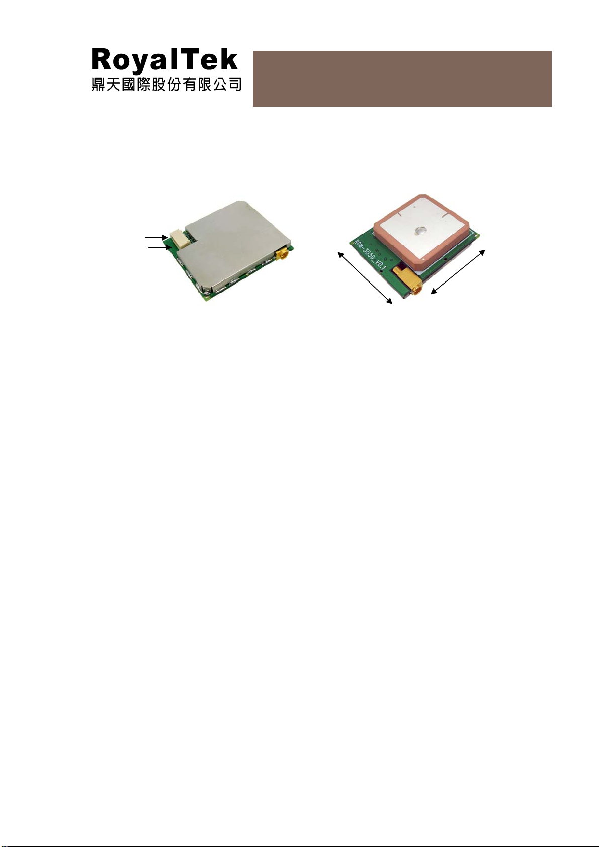
2. RGM-3550LP Picture and Pin Definition
Pin 1
Pin 6
31 ±0.3 mm 35 ± 0.3mm
5
Page 6
b
RGM-3550LP User Manual
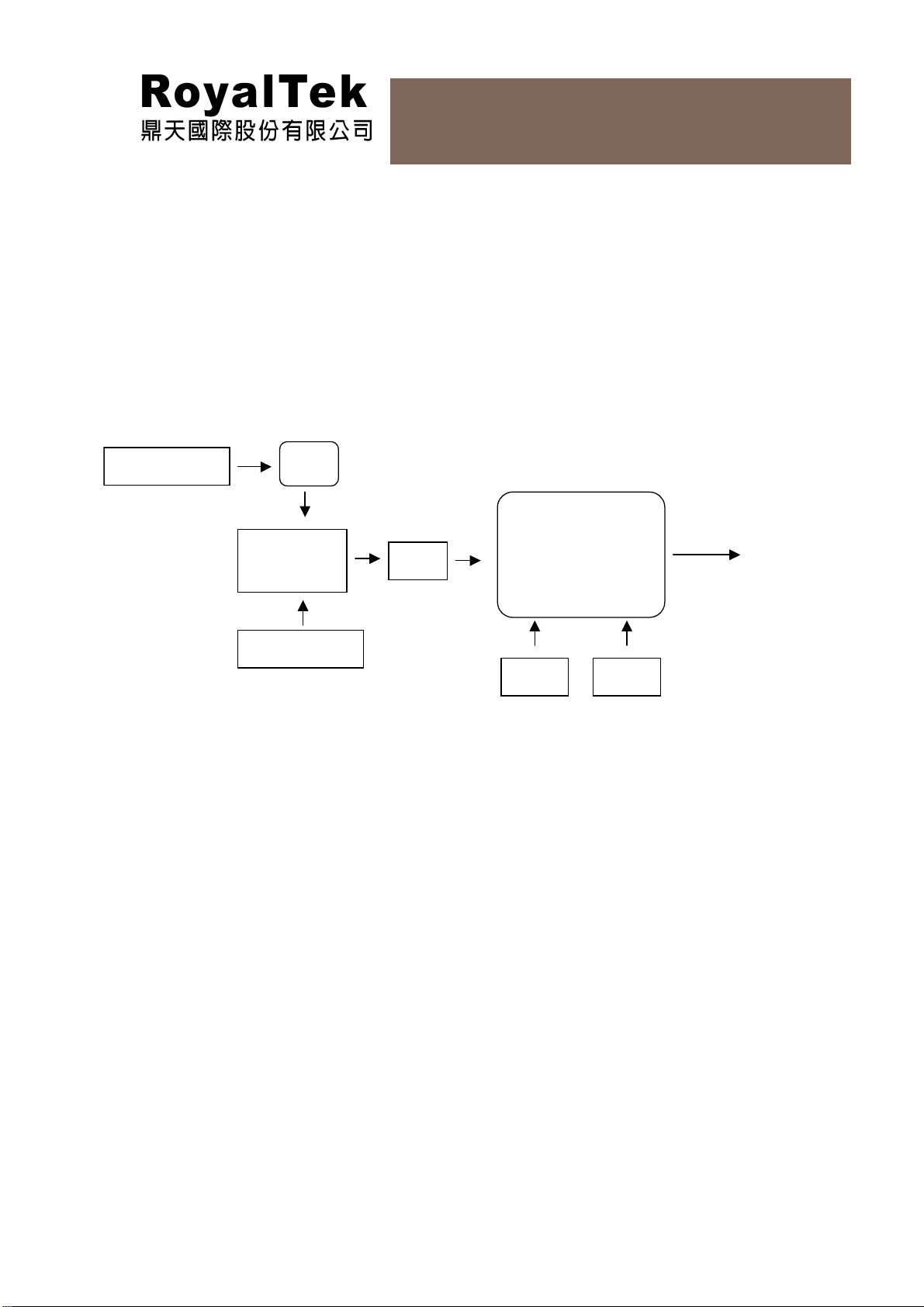
3. RGM-3550LP System Block Diagram
System block diagram description:
Patch antenna with 1 Stage LNA
4Mega bits flash memory on chip
MMCX External Antenna Supported
6 pin I/O pin (see page 7, Interface pin definition)
GPS Patch Antenna
LNA
MMCX Switch
Connector
External Antenna
SAW
SIRF GSC3F
with 4M Flash
RF frontend +BaseProcessor
TCXO XTAL
6 Pin I/O
and
6
Page 7

RGM-3550LP User Manual
4. RGM-3550LP Technique Specification
No Function Specification
GPS receiver
1 Chipset SiRF GSC3F/LP single chipset
2 Frequency L1 1575.42MHz.
3 Code C.A. Code.
4 Channels 20.
5 Chipset Sensitivity
6 Cold start 35 sec@ open sky
7 Warm start 35 sec@ open sky
8 Hot start 1 sec @ open sky
9 Reacquisition 0.1sec typical
9 Position accuracy 10meters at 2D RMS.
10 Maximum altitude 18000 m
11 Maximum velocity 514 m/s
12 Trickle power mode
13 Update rate Continuous operation: 1Hz
14 Testability It shall be able to be tested by SiRF test mode IV and
15 Protocol setup It shall store the protocol setup in the SRAM memory.
Interface
16 I/O Pin 6 pin (see page 7 about pin definition)
Mechanical requirements
-159dBm (tracking)
Duty cycle ≦ 34%. (Variable)
single channel simulator.
17 Dimension 35±0.3(L)x 31±0.3(W)x 8.55±0.5(H) mm
18 Weight
Power consumption
19 Vcc DC 3.3 ±5%
20 Current Acquisition: 50mA (typical) Tracking: 45mA (typical)
21 Trickle power mode Average current 37mA. (300ms on /700ms off)
22 SRAM backup battery 3.3mAhr Li-Ion rechargeable battery. Battery life at full
Environment
23 Operating temperature
≦16.5g
charge is ≥ 7 days.
-40 ~ +85℃
(except for SRAM battery backup -20
to +60 degree Celsius)
7
Page 8

±
=
=
RGM-3550LP User Manual
24 Storage temperature
-40 ~ +85℃
to +60 degree Celsius)
25 Humidity
26 Lead Free Yes
External Antenna RF Input
27
Drive Output Voltage
28 Drive Output Current 30mA (max)
29 Connector Type MMCX
≦95%
2.85V ± 0.5%
Interface Pin definition (VDD=2.85V±2%)
1. 2. 3 . 4. 5. 6
(except for SRAM battery backup -40
EXT Ant
RF IN
Pin # Signal Name I/O Description Characteristics
1 RX I Serial port A
2 TXA O Serial port A
3 GND G Ground Reference Ground
4 VCC I DC Supply
Voltage input
5 GPS Status O GPS Status
6 Boot select I Boot mode
EXT
Ant
RFIN
VCC (+3.3V DC power Input)
GND
External
Antenna
RF Input
this is the main DC power supply input pin. It provides voltage to module.
Reference Ground Plane of RGM-3550.
RF IN
External
Antenna RF
Input
DC +3.3V±5%
OUT
Out
VV
ILIH
ILIH
%5.085.2
)(30 MaxmAI
OLOH
OLOH
VDDVVDDV
*3.0 *7.0 ≤≥
VDDVVDDV
25.0 *75.0 ≤≥
VDDVVDDV
25.0 *75.0 ≤≥
VDDVVDDV
*3.0 *7.0 ≤≥
Boot select
set this pin to high for programming flash.
8
Page 9

±
=
=
RGM-3550LP User Manual
RX
This is the main receiver channel and is used to receive software commands to
the board from SIRFdemo software or from user written software.
PS: Pull up if not used.
TX
This is the main transmitting channel and is used to output navigation and
measurement data to SiRFdemo or user written software.
GPS Status
GPS Status Pin can be connected to a LED to indicate the status of GPS signal
1. Solid: Power ON/ Tracking for Satellite
2. Blinking: 3D Fix Found
GPS status light indicating
Power off LED off VoL:0.71(Max)
Power on/search for satellite, voltage is high LED solid VoH: 2.13V(min)
3D fix found, voltage is high/low, remain 1
LED blinking
second each
External Antenna RF Input
This is the MMCX RF Connector for External Active Antenna signal input
VoH: 2.13V(min) &
VoL:0.71(Max)
External Active Antenna Spec. Suggestion
1. Drive Output Voltage:
2. Drive Output Current: )(30 MaxmAI
OUT
Out
VV
%5.085.2
3. LNA Gain: 20~26dB
4. LNA Noise Figure: <1.5dB
How to use RGM-3550LP in 5V main board
The power supply of RGM-3550LP is 3V. If customer would like use RGM-3550LP in
5V system, RoyalTek suggest customer use linear regulator (from 5V to 3.3V) on
customer main board. We could help check the circuit if providing regulator
specification.
9
Page 10

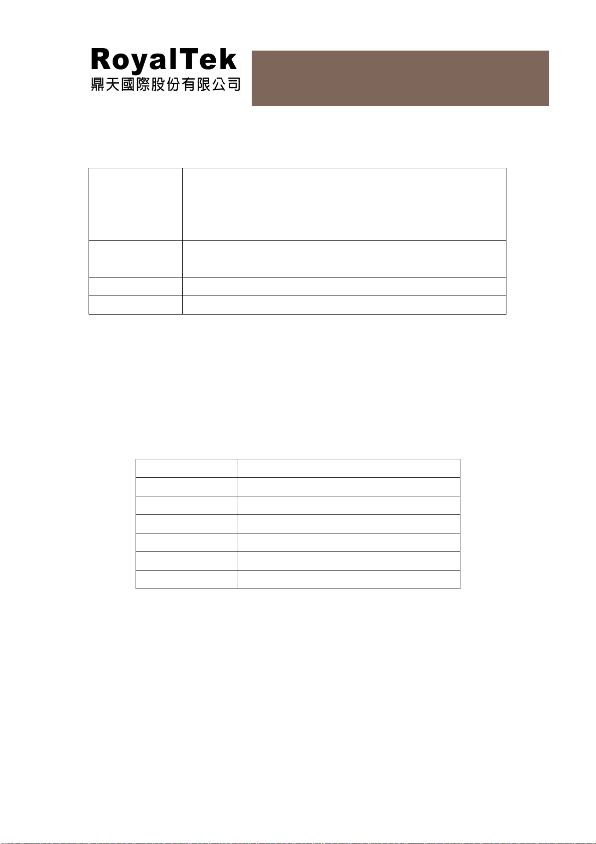
5. Mechanical Layout
25x25x4mm patch antenna
RGM-3550LP User Manual
25x25x2mm patch antenna
10
Page 11

RGM-3550LP User Manual
6. How to Assemble/Fix RGM-3550LP
Below is our recommendation to assemble/fix up RGM-3550LP GPS module
on the customer board or device case.
Hole
Hole
11
Page 12
RGM-3550LP User Manual
7. Software Specification and NMEA Protocol
Software Specification
- Standard SiRF firmware for SSIII (GSW3 & SiRFLoc 3)
GPS Firmware
- Upload firmware
- RGM-3550LP [GSW3][SBAS GGA(1), GSA(1), GSV(1),
RMC(1) 9600 GPS Firmware, version 2.1.0.123 (default)
GPS Utility
- A GPS performance diagnostic utility is required
- C/NO, TTFF
WAAS
GPS status
- Enable
- See GPS status light indicating specification
NMEA V3.0 Protocol
Its output signal level is TTL: 9600bps (default), 8 bit data, 1 stop bit and no parity. It supports
the following NMEA-0183
Messages: GGA, GLL, GSA, GSV, RMC and VTG.
NMEA Output Messages: the Engine board outputs the following m essages as shown in Tabl e
1:
Table 1 NMEA-0183 Output Messages
NMEA Record Description
GGA Global positioning system fixed data
GLL Geographic position – latitude / longitude
GSA GNSS DOP and active satellites
GSV GNSS satellites in view
RMC Recommended minimum specific GNSS data
VTG Course over ground and ground speed
GGA-Global Positioning System Fixed Data
Table 2 contains the values of the following example:
$GPGGA, 161229.487, 3723.2475, N, 12158.3416, W, 1, 07, 1.0, 9.0, M, , , ,0000*18
12
Page 13

RGM-3550LP User Manual
Table 2 GGA Data Format
Name Example Units Description
Message ID $GPGGA GGA protocol header
UTC Position 161229.487 hhmmss.sss
Latitude 3723.2475 ddmm.mmmm
N/S Indicator N N=north or S=south
Longitude 12158.3416 Dddmm.mmmm
E/W Indicator W E=east or W=west
Position Fix Indicator 1 See Table 2-1
Satellites Used 07 Range 0 to 12
HDOP 1.0 Horizontal Dilution of Precision
MSL Altitude 9.0 meters
Units M meters
Geoid Separation meters
Units M meters
Age of Diff. Corr. second Null fields when DGPS is not
used
Diff. Ref. Station ID 0000
Checksum *18
<CR><LF>
End of message termination
Table 3 Position Fix Indicators
Value Description
0 Fix not available or invalid
1 GPS SPS Mode, fix valid
2 Differential GPS, SPS Mode, fix valid
3 GPS PPS Mode, fix valid
GLL-Geographic Position –Latitude/Longitude
Table 3 contains the values of the following
Example: $GPGLL, 3723.2475, N, 12158.3416, W, 161229.487, A*2C
13
Page 14

RGM-3550LP User Manual
Table 3 GLL Data Format
Name Example Units Description
Message ID $GPGLL GLL protocol header
Latitude 3723.2475 ddmm.mmmm
N/S Indicator N N=north or S=south
Longitude 12158.3416 Dddmm.mmmm
E/W Indicator W E=east or W=west
UTC Position 161229.487 hhmmss.ss
Status A A=data valid or V=data not valid
Checksum *2C
<CR><LF>
End of message termination
GSA-GNSS DOP and Active Satellites
Table 4 contains the values of the following example:
$GPGSA, A, 3, 07, 02, 26, 27, 09, 04, 15, , , , , , 1.8,1.0,1.5*33
Table 4 GSA Data Format
Name Example Units Description
Message ID $GPGSA GSA protocol header
Mode 1 A See Table 4-2
Mode 2 3 See Table 4-1
Satellite Used 07 Sv on Cha nnel 1
Satellite Used 02 Sv on Cha nnel 2
…. ….
Satellite Used Sv on Channel 12
PDOP 1.8 Position Dil ution of Precision
HDOP 1.0 Horizontal Dilution of Precision
VDOP 1.5 Vertical Dilution of Precision
Checksum *33
<CR><LF>
End of message termination
Table 4-1 Mode 1
Value Description
1 Fix not available
2 2D
3 3D
14
Page 15

RGM-3550LP User Manual
Table 4-2 Mode 2
Value Description
M Manual-forced to operate in 2D or 3D mode
A Automatic-allowed to automatically switch 2D/3D
GSV-GNSS Satellites in View
Table 5 contains the values of the following example:
$GPGSV, 2, 1, 07, 07, 79, 048, 42, 02, 51, 062, 43, 26, 36, 256, 42, 27, 27, 138,
42*71$GPGSV, 2, 2, 07, 09, 23, 313, 42, 04, 19, 159, 41, 15, 12, 041, 42*41
Table 5 GGA Data Format
Name Example Units Description
Message ID $GPGSV GSV protocol header
Number of
Messages1
Messages Number1 1 Ran ge 1 to 3
Satellites in View 07
Satellite ID 07 Channel 1(Range 1 to 32)
Elevation 79 degrees Channel 1(Maximum 90)
Azimuth 048 degrees Channel 1(True, Range 0 to 359)
SNR (C/No) 42 dBHz Ran ge 0 to 99, null when not
…. ….
Satellite ID 27 Channel 4(Range 1 to 32)
Elevation 27 degrees Channel 4(Maximum 90)
Azimuth 138 degrees Channel 4(True, Range 0 to 359)
SNR (C/No) 42 dBHz Ran ge 0 to 99, null when not
2 Range 1 to 3
tracking
tracking
Checksum *71
<CR><LF>
1
Depending on the number of satellites tracked multiple messages of GSV data may be required.
End of message termination
RMC-Recommended Minimum Specific GNSS Data
Table 6 contains the values of the following example:
$GPRMC, 161229.487, A, 3723.2475, N, 12158.3416, W, 0.13, 309.62, 120598, ,*10
15
Page 16

RGM-3550LP User Manual
Table 6 GGA Data Format
Name Example Units Description
Message ID $GPRMC RMC protocol header
UTC Position 161229.487 hhmmss.sss
Status A A=data valid or V=data not valid
Latitude 3723.2475 ddmm.mmmm
N/S Indicator N N=north or S=south
Longitude 12158.3416 dddmm.mmmm
E/W Indicator W E=east or W=west
Speed Over Ground 0.13 knots
Course Over
Ground
Date 120598 ddmmyy
Magnetic Variation degrees E=east or W=west
Checksum *10
<CR><LF>
309.62 degrees True
End of message termination
VTG-Course Over Ground and Ground Speed
Table 7 contains the values of the following example:
$GPVTG, 309.62, T, , M, 0.13, N, 0.2, K*6E
Table 7 VTG Data Format
Name Example Units Description
Message ID $GPVTG VTG protocol header
Course 309.62 degrees Measured heading
Reference T True
Course degrees Measured heading
Reference M Magnetic
Speed 0.13 knots Measured horizontal speed
Units N Knots
Speed 0.2 km/hr Measured horizontal speed
Units K Kilometer per hour
Checksum *6E
<CR><LF>
End of message termination
16
Page 17

RGM-3550LP User Manual
GPS Receiver User’s Tip
1. GPS signal will be affected by weather and environment conditions, thus suggest to use the
GPS receiver under less shielding environments to ensure GPS receiver has better receiving
performance.
2. When GPS receiver is moving, it will prolong the time to fix the position, so suggest to wait for
the satellite signals to be locked at a fixed point when first power-on the GPS receiver to
ensure to lock the GPS signal at the shortest time.
3. The following situation will affect the GPS receiving performance:
a. Solar control filmed windows.
b. Metal shielded, such as umbrella, or in vehicle.
c. Among high buildings.
d. Under bridges or tunnels.
e. Under high voltage cables or near by radio wave sources, such as mobile phone base
stations.
f. Bad or heavy cloudy weather.
4. If the satellite signals can not be locked or encounter receiving problem (while in the urban
area), the following steps are suggested:
a. Please plug the external active antenna into GPS receiver and put the antenna on
outdoor or the roof of the vehicle for better receiving performance.
b. Move to another open space or reposition GPS receiver toward the direction with less
blockage.
c. Move the GPS receiver away from the interferences resources.
d. Wait until the weather condition is improved.
5. While a GPS with a backup battery, the GPS receiver can fix a position immediately at next
power-on if the build-in backup battery is full-recharged.
Copyright © 2007-2008, RoyalTek Company Lt d.
Page 18

RGM-3550LP User Manual
8. Package Specification and Order Information
1
2 3
Copyright © 2007-2008, RoyalTek Company Lt d.
 Loading...