

Page 1
Onyx
RFG-2000 GPS Receiver
User Manual
RFG-2000 Ver1.0c,
April/2/04’
1
Page 2

Contents
WHAT IS ONYX, RFG-2000..................................................................................................3
WHAT IS INSIDE.....................................................................................................................3
WHAT IS GPS..........................................................................................................................3
WHAT’S INSIDE THE PACKAGE........................................................................................4
START-UP FOR RFG-2000 (PDA).......................................................................................6
USB DRIVER INSTALLATION FOR WINDOWS OPERATION SYSTEM ...................7
USB DRIVER UN-INSTALLATION FOR WINDOWS OPERATION SYSTEM ............ 8
USB DRIVER INSTALLATION FOR POCKET PC...........................................................9
USB DRIVER UN-INSTALLATION FOR POCKET PC.................................................... 9
HOW TO TEST RFG-2000 (PDA VERSION ONLY) ....................................................... 11
SPECIFICATIONS.................................................................................................................17
SOFTWARE DATA................................................................................................................19
TROUBLESHOOTING.........................................................................................................25
APPENDIX: CONNECTOR INTERFACE .........................................................................26
LIMITED WARRANTY..........................................................................................................27
2
Page 3

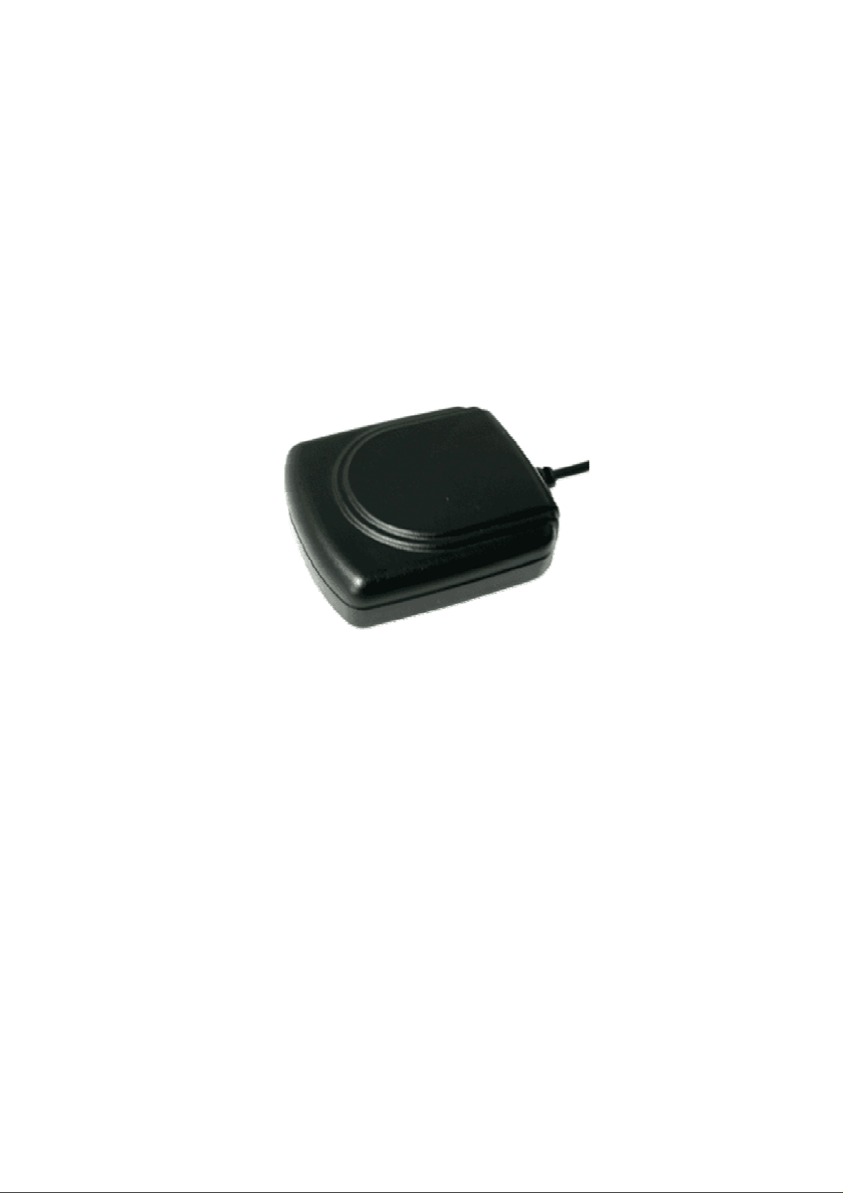
What is Onyx, RFG-2000
Congratulation on your purchase of Onyx, offering diverse GPS (Global
Positioning System) applications. Onyx GPS receiver, RFG-2000, is a GPS
mouse targeted on clients using in automotive, fleet vehicle, and electronics
applications where a small and highly accurate GPS receiver is required. It
provides a GPS measurement platform that performs the processor-intensive
GPS tracking and processing tasks. Its 12-channel integrated receiver and
one-second navigation update rate allows for continuous tracking of all visible
satellites, and it can provide your exact location information soon after the
power is on. With the waterproof, industrial level design and the different
interfaces for laptops and PDAs, RFG-2000 can guide you in the air, land and
water as a highly reliable, long-lasting Navigator. It is the most cost effective
GPS-Mouse in the world.
What Is Inside
Before you start up, make sure that your package includes the following items.
If any items are missing or damaged, contact RoyalTek immediately. Please
refer to the contact information on the last page of this manual.
◆GPS Receiver ◆ Cable(RS-232 , USB, or PDA adaptor)
◆CD Disc(optional)
What Is GPS
In 1974 the USA Department of Defense set about developing a Global
Positioning System (GPS), a constellation of 24 satellites that Orbits 12,000
miles above the Earth. Using triangulation of signals from four of the satellites,
a receiving unit on earth can pinpoint its current location to within a few
meters. A GPS device receives the data, converts the longitude, latitude, and
altitude (LLA) data into a location point. Position and navigation information is
vital to a wide range of professional and recreational activities covering
surveying, search and rescue, tracking, hiking, navigating, and so forth.
3
Page 4
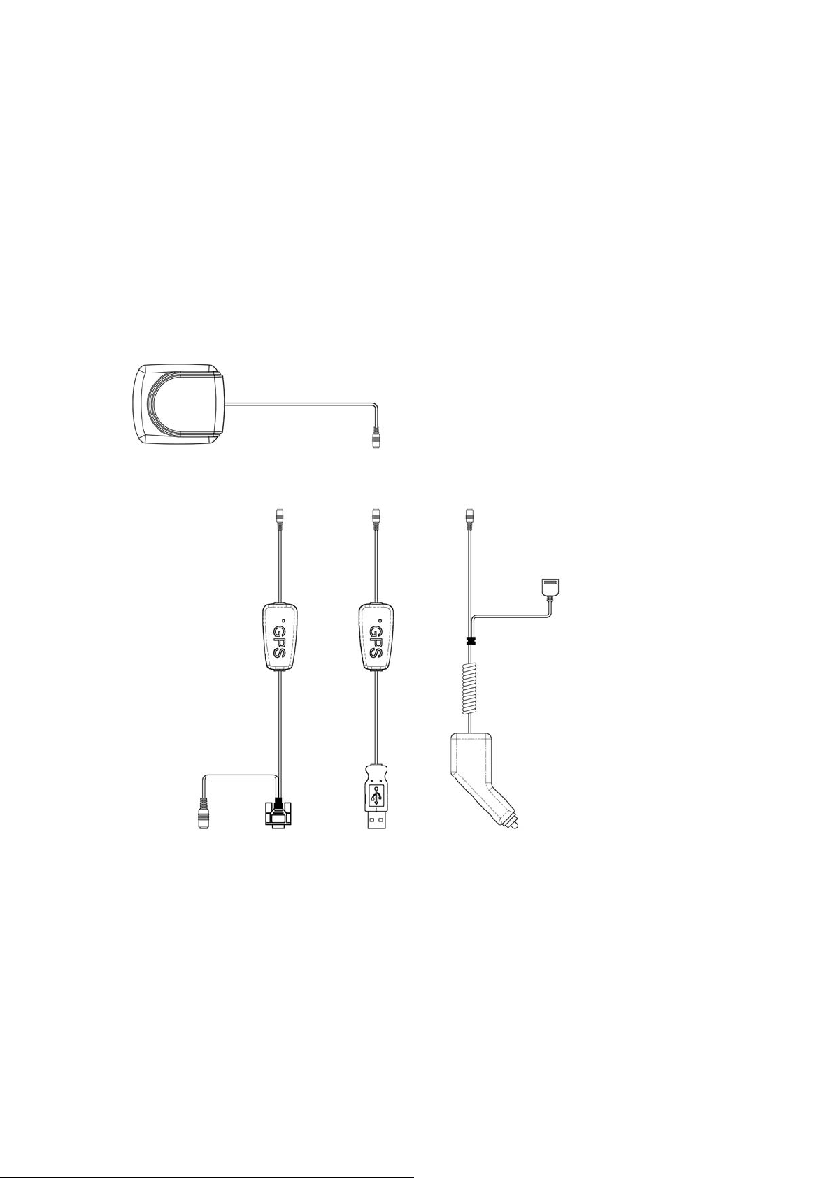
What’s Inside the Package
Before you start up, make sure your package includes the following items. If
any item is missing or damaged, contact your dealer immediately. Please refer
to the contact information on the last page of this manual.
◆ GPS Receiver ◆ Application CD
◆ Cable for RS232 , USB , or PDA adaptor(depending on what you buy)
RFG-2000
PDA Cable Selection
1.iPAQ 36xx/37xx/38xx/
39xx/19xx series
2.iPAQ B5450/2210
3.HP Jornada 54x/56x series
4.Fujitsu-Siemens LOOX series
5.Casio e125/e500
6.Dell Axim X5
7.ETEN P300/P700
8.O2 XPDA series
9.Yakumo Delta
10.NEC 200E/300E
11.Mitac MIO338/399/528/558
12.ViewSonic V35
13.Asus A-600/A-620
RS-232/PS2 USB
14.Palm 5xx series/Tungsten T/
Tungsten C/Zire71
15.Toshiba e740/e330/e335/
e350/e400/e750
For other various PDA cables,
Car cigarette
please refer to our web site.
adaptor 12V
4
Page 5
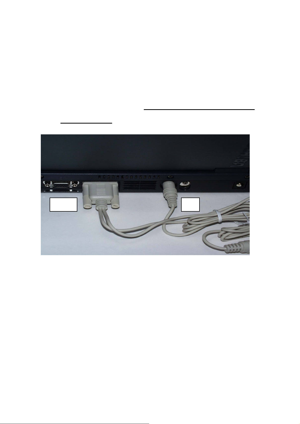
Start-Up for RFG-2000 (RS-232 & USB)
Getting Started
Step 1: Plug-in RS-232 or USB cable to your laptop or desktop PC.
Step 2:Install USB driver if you use USB cable to connect RFG-2000 to your
PC.(for detail, please go to USB driver installation for Windows
Operation System)
RS-232 PS2
Step 3:Choose the correct COM port and baud rate (4800bps) for map or
navigation software.
Step 4: Place your Onyx on the outside roof of your vehicle with magnetic
base if you encounter any problem to receive GPS signal.
Notice:
(1) For safety reason, please do not install RFG-2000 while driving.
(2) The formats of NMEA messages are illustrated on Software Data section.
5
Page 6

(3) It is strongly recommend that user doesn’t plug and unplug this connector
frequently.
Start-Up for RFG-2000 (PDA)
Getting Started
Step 1: Plug-in PDA connector to your PDA.
Step 2: Connect the car cigarette adaptor to your car.
Step 3:Choose the correct COM port and baud rate (4800bps) for map or
navigation software.
Step 4: Place your Onyx on the outside roof of your vehicle with magnetic
base if you encounter any problem to receive GPS signal.
6
Page 7
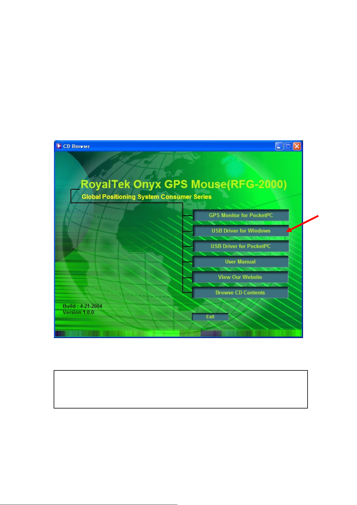
USB Driver Installation for Windows
Operation System
Getting Started
Step 1: Plug USB connector to USB port of your laptop or desktop PC.
Step 2: Insert RFG-2000 CD-Disc, choose “USB Driver for Windows” item to
install USB driver for Windows Operation System.
Step 3: There is alternative way to install USB driver by selecting
”/USB Driver/PL-2302 Driver installer.exe” file and double click to run.
Caution: During USB driver installation, a message box “Driver is not certificated by
Microsoft” may pop-up. Please crick “Continue” to continue the US B driver
installation.
7
Page 8
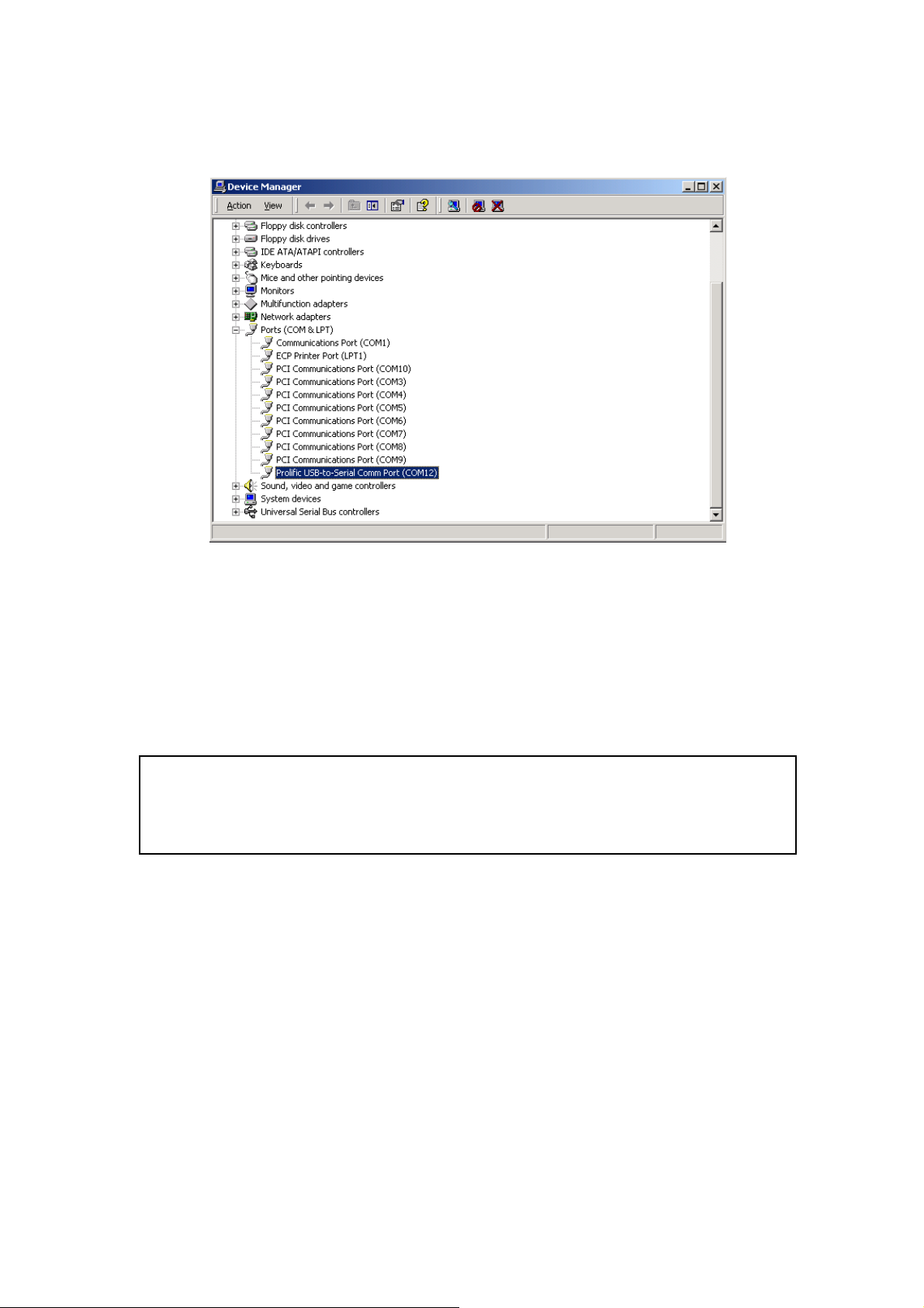
Step 4. You can check COM port number of RFG-2000 from System
properties now. The COM port is COM3 in this example.
Step 5: Place your Onyx on the outside roof of your vehicle with magnetic
base if you encounter any problem to receive GPS signal (optional).
Step 6: Choose the correct COM port and baud rate (4800bps) for map or
navigation software.
Caution: Sometimes, USB driver can’t work properly after recovering from power-saving
mode. To solve this problem, please restart your PC and disable power-saving
function.
USB Driver Un-Installation for Windows
Operation System
To completely remove the USB-driver, please run “/USB Driver/PL-2302
Driver installer.exe” in RFG-2000 CD.
8
Page 9
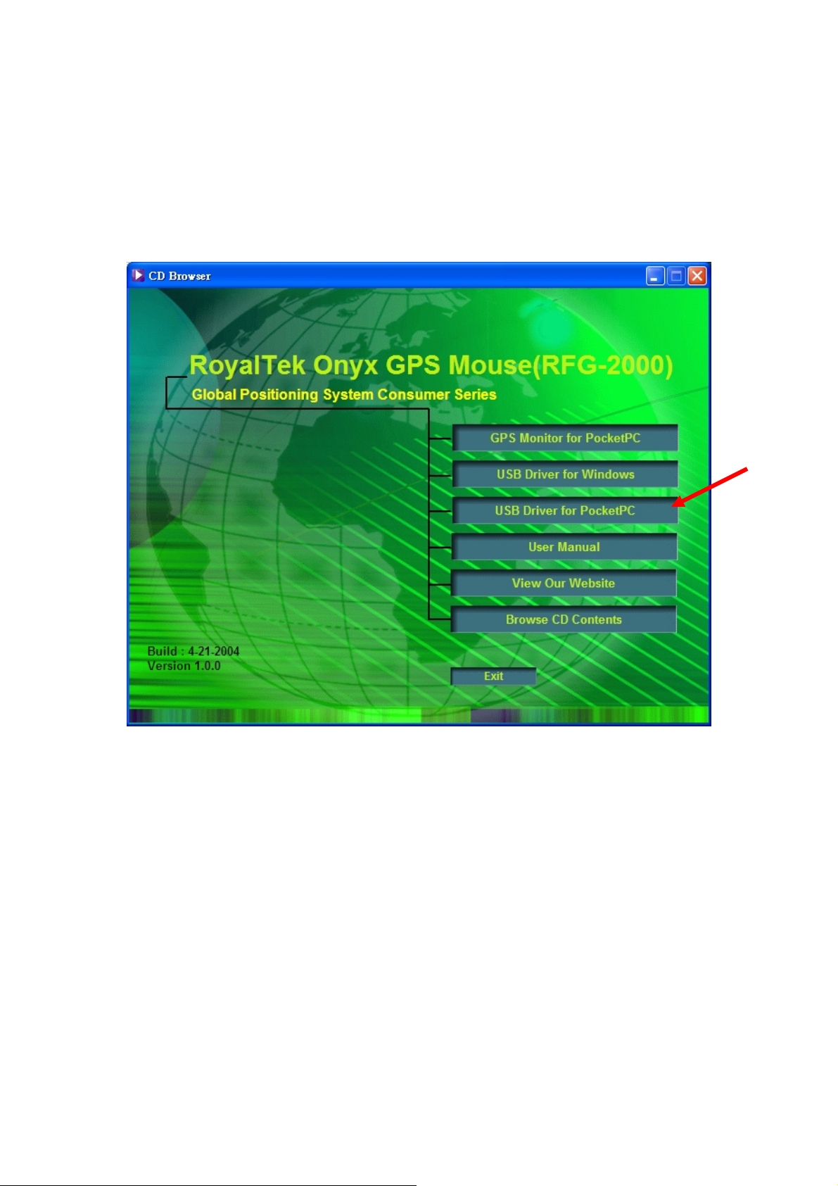
USB Driver Installation for Pocket PC
The RFG-2000 Installation CD provides the Pocket PC USB driver installation.
If your Pocket PC need to install USB Driver for RFG-2000, you should
choose the “USB Driver for PocketPC” item to install.
USB Driver Un-Installation for Pocket PC
Step 1: Go to Start->Setting->System->Remove Program
Step 2: Select “RoyalTek PL-2303 USB Driver” for un-installation.
9
Page 10

10
Page 11

How to test RFG-2000 (PDA version only)
1. Insert RFG-2000 CD-Disc, choose “GPS Monitor for PocketPC” item to
install the PocketPC version of RoyalTek GPS Monitor test application.
2. Execute the Pocket PC version of RFG-2000 GPS test application by
double clicking the “RoyalTek GPS Monitor” icon as shown.
11
Page 12

3. The RoyalTek GPS Monitor main screen as shown.
12-Channel Signal Level Color Coding
Red Color: The satellite is known from almanac information; however, the satellite is not
currently being tracked.
Blue Color: The satellite is being tracked; however, it is not being used in the current
position solution.
12
Page 13

Green Color: The satellite is being tracked and is being used in the current position
solution
.
4. Select [File]->[Connect/Disconnect] menu item to prompt Com Port
Setting window. Please choose the correct COM port.
Greed LED: Fix
Red LED: Not Fix
While LED: No data
The baud rate of the RFG-2000 was defaulted as 4800 bps.
5. If everything is OK, it will show the position information and satellite’s
constellation.
13
Page 14

6. Select [View] menu and select different view modes including Satellites
View, Navigation View and Development View as below.
14
Page 15

7. If you want to cold start the GPS receiver, select “Cold Start” from the
“Function” menu and click “Action” icon, the system will clear the
RFG-2000 module data and initialize a cold start on GPS receiver.
8. Select [File]->[NMEA Config] menu item to prompt NMEA Configuration
window. Please select output NMEA sentences.
15
Page 16

16
Page 17

Specifications
Physical characteristics
Dimension: 57±0.3(Length) X 50 ±0.3(Width) X 15.5 ±0.3(Height)
Weight: 70 +/- 5 grams
Temperature characteristics
Storage temperature: -40℃ ~ +85℃
Operating temperature: -40℃ ~ +85℃
General
Channels: 12 channels
L1: 1575.42 MHz
C/A code: 1.023MHz chip rate
Accuracy
Position accuracy: 15 meters (49 feet) RMS
Velocity accuracy: 0.1 knot RMS steady state
Datum
WGS-84
Position update rate
1Hz, once per second
Dynamic conditions
Altitude :18000 meters (60000 feet) max
Velocity :515 meters / second max
Jerk :20 meters / second, max
Acceleration :4 G, max
Power
PS2/USB input power: DC 5V ± 5 %, 55mA typical
Car cigarette power adaptor: +9V ~ +16V.
17
Page 18

Certification
FCC/CE compliant
Waterproof standard
IEC 68-2-18 test Ral
18
Page 19

Software Data
NMEA 0183 V3.0 Protocol
It is the RS-232 interface:4800 bps, 8 bit data, 1 stop bit and no parity.
NMEA Output Messages
The RFG-2000 outputs the following messages as shown in Table 1:
TABLE 1 NMEA OUTPUT MESSAGES
NMEA Record Description
GGA Global positioning system fixed data
GLL Geographic position – Latitude/Longitude
GSA GNSS DOP and active satellites
GSV GNSS satellites in view
RMC Recommended minimum specific GNSS data
VTG Course over ground and ground speed
GGA-Global Positioning System Fixed Data
Time, position and fix related data for a GPS receiver.
$GPGGA,hhmmss.dd,xxmm.dddd,<N|S>,yyymm.dddd,<E|W>,v,ss,d.d,h.h ,M,g.g,M,a.a,xxxx*
hh<CR><LF>
Example:
$GPGGA,111200.02,6016.3092,N,02458.3841,E,1,09,0.8,30.6,M,18.1,M,,*5D
Name Example Units Description
Message ID $GPGGA
UTC Time 1 11200.02
Latitude 6016.3092
<N|S> Indicator N
Longitude 02458.3841
GGA protocol heade r
hhmmss.dd
hh = hours
mm = minutes
ss = seconds
dd = decimal parts of seconds
xxmm.dddd
xx = degrees
mm = minutes
dd = decimal parts of minutes
N=north or S=south
yyymm.dddd
yyy = degrees
mm = minutes
19
Page 20

dddd = decimal parts of minutes
<E|W> Indicator E
Fix Valid Indicator 1
Satellites Used 09
HDOP 1.0
MSL Altitude 9.0 meters
Units M meters
Geoid Separation meters
Units M meters
NULL
NULL
Checksum *5D
<CR><LF>
E=east or W=west
v
0 = Fix not valid
1 = Fix valid
ss
Number of satellites used in position fix,
00-12. Fixed length
d.d
Horizontal Dilution of Precision
h.h
Altitude(mean-sea-level, geoid)
Letter M
g.g
Difference between the WGS-84 reference
ellipsoid surface and the mean-sea-level
altitude.
Letter M
a.a
NULL (missing)
xxxx
NULL (missing)
*hh
End of message termination
GLL-Geographic Position – Latitude/Logitude
Latitude and Longitude, UTC time of fix and status.
$GPGLL,xxmm.dddd,<N|S>,yyymm.dddd,<E|W>,hhmmss.dd,S,M*hh<CR><LF>
Example:
$GPGLL,6016.3073,N,02458.3791,E,134157.48,A,A*26
Name Example Units Description
Message ID $GPGLL
Latitude 6016.3073
<N|S> Indicator N
Longitude 02458.3791
<E|W> Indicator E
UTC Time 134157.48
GLL protocol header
xxmm.dddd
xx = degrees
mm = minutes
dd = decimal parts of minutes
N=north or S=south
yyymm.dddd
yyy = degrees
mm = minutes
dddd = decimal parts of minutes
E = East, W = West
hhmmss.dd
hh = hours
20
Page 21

mm = minutes
ss = seconds
dd = decimal parts of seconds
Status Indicator A
Mode Indicator A
Checksum *26
A = valid
V = invalid
A=autonomous
N=data not valid
*hh
<CR><LF>
End of message termination
GSA-GNSS DOP and Active Satellites
GPS receiver operating mode, satellites used in the navigation solution
reported by the GGA sentence, and DOP values.
$GPGSA,a,b,xx,xx,xx,xx,xx,xx,xx,xx,xx,xx,xx,xx,p.p,h.h,v.v*hh<CR><LF>
Example:
$GPGSA,A,3,03,15,17,18,22, 23,,,,,,,4.7,3.7,2.9*37
Name Example Units Description
Message ID $GPGSA
Mode 1 A
Mode 2 3
Satellite Used 03
PDOP 4.7
GSA protocol header
a
Mode: M = Manual, forced to operate in 2D
or 3D mode. A = Automatic, allowed to
automatically switch 2D/3D.
b
Mode: 1 = Fix not available, 2 = 2D, 3 = 3D
xx
ID (PRN) numbers of GPS satellites used in
solution
p.p
Position Dilution of Precision
HDOP 3.7
VDOP 2.9
Checksum *37
<CR><LF>
h.h
Horizontal Dilution of Precision
v.v
Vertical Dilution of Preci sio n
*hh
End of message termination
GSV-GNSS Satellites in View
Number of satellites in view, satellite ID (PRN) numbers, elevation, azimuth,
21
Page 22

and SNR value. The information for four satellites maximum per one message,
additional messages up to maximum of eight sent as needed. The satellites
are in PRN number order.
Before a position fix is acquired the information contains only the SNR (signal
to noise ratio) value. After a fix is acquired, also the elevation and azimuth
angles are added. Note that there can be also “theoretical” satellites in the
GSV message. These are satellites of which the angles (elevation, azimuth)
are known but for some reason, e.g. due to an obstruction, have not been
found by Onyx. The SNR value for these satellites is set to zero.
Please notice that as all the satellites that in the view are reported, the
amount of satellites may occasionally be more than the number of receiver
tracking channels, 12.
$GPGSV,n,m,ss,xx,ee,aaa,cn,…………. ,xx,ee,aaa,cn*hh<CR><LF>
Example:
$GPGSV 4,1,14,03,66,207,50,08,09,322,44,11,01,266,42,14,00,155,00*79
$GPGSV,4,2,14,15,41,088,48,17,21,083,44,18,57,087,51,21,57,173,50*78
$GPGSV,4,3,14,22,05,203,00,23,52,074,49,26,17,028,44,27,00,300,00*79
$GPGSV,4,4,14,28,32,243,00,31,48,286,00*70
Name Example Units Description
Message ID $GPGSV
Number of Messages 4
Messages Number 1
Satellites in View 14
Satellite ID 03
Elevation 66 degrees
Azimuth 207 degrees
SNR (C/No) 50 dBHz
…. … …
GSV protocol header
n
Total number of messages, 1 to 9
m
Message number, 1 to 9
ss
Total number of satellites in view
xx
Satellite ID (PRN) number
ee
Satellite elevation, degrees 90 max
aaa
Satellite azimuth, degrees True, 000 to
359
cn
SNR ( C/No) 00-99 dB-Hz. zero when
not tracking
….
Checksum *79
22
*hh
Page 23

<CR><LF>
End of message termination
RMC-Recommended Minimum Specific GNSS Data
Time, date, position, course and speed data.
$GPRMC,hhmmss.dd,S,xxmm.dddd,<N|S>,yyymm.dddd,<E|W>,s.s,h.h,ddmmyy,d.d,
<E|W>,M*hh<CR><LF>
Example:
$GPRMC,134829.486,A,1126.6639,S,11133.3299,W,58.31,309.62,110200,,,A*14
Name Example Units Description
Message ID $GPRMC
UTC Time 134829.486
Status Indicator A
Latitude 1126.6639
N/S Indicator S
Longitude 11133.3299
E/W Indicator W
Speed, Knots 58.31 knots
Heading 309.62 degrees
Date 110200
Magnetic Variation degrees
Declination
Mode Indicator A
RMC protocol header
hhmmss.dd
hh = hours
mm = minutes
ss = seconds
dd = decimal parts of seconds
S
A=data valid or V=data not valid
xxmm.dddd
xx = degrees
mm = minutes
dd = decimal parts of minutes
N=north or S=south
yyymm.dddd
yyy = degrees
mm = minutes
dddd = decimal parts of minutes
E=east or W=west
s.s
Speed, knots.
ddmmyy
dd – date
mm = month
yy = year
d.d
This value is available if magnetic
model data has been stored to the
flash memory.
E = East, W = West
A=autonomous
N=data not valid
23
Page 24

Checksum *14
*hh
<CR><LF>
End of message termination
VTG-Course over ground and ground speed
Course and speed.
$GPVTG,h.h,T,m.m,M,s.s,N,s.s,K,M*hh<CR><LF>
Example:
$GPVTG,202.60,T,,,0.38,N,0.7,K,A*0D
Name Example Units Description
Message ID $GPVTG
Heading
202.60 Degrees
Heading Units T
Magnetic Heading
Magnetic Heading
Degrees
Units
VTG protocol header
h.h
Letter T
m.m
This value is available if magnetic model
data has been stored to the flash memory
Letter M
Speed, Knots 0.38 Knots
Speed Unit N
Speed
0.7 km/h
K
Mode Indicator A
Checksum *0D
<CR><LF>
s.s
Speed, knots.
Letter N
s.s
Letter of K
A=autonomous
N=data not valid
*hh
End of message termination
24
Page 25

Troubleshooting
A
Problem Reason Solution
Test Fail
No position output
but timer is counting
port
If operated Onyx over
5 minutes with
nothing showing on
the tracking diagram
Poor connection or can’t
find GPS module
Wrong BIOS setting for
PS2
t outdoor space but GPS
signal is blocked by
buildings
Some other application is
using the COM port.
PDA Low Battery Using AC/DC charge for recharge
Maybe Onyx received not
enough date to sure
tracking
Check the RS232 and PS2
connector or USB connector to
make sure they are well connected.
Check the RFG-2000 is inserted
correctly.
Check the BIOS setting to make
sure the PS2 port is enable.
If you still get the testing fail
message, contact your local
distributor
Go outdoors where you can see
clear sky and retest Oynx again,
Reset the Pocket PC. Can’t Open COM
Utilize the Pocket PC test program –
RoyalTek GPS Monitor program to
reset Onyx.
Note
z Please don’t expose the unit under the sun for long period of time.
z Please don’t leave the unit in the vehicle while not using.
z Please perform Cold start if last fixed position is more than 500km away
from the present position.
z Please adjust your PDA system time to correct local time to achieve better
GPS performance. Incorrect PDA system time may cause poor TTFF(Time
To First Fix).
25
Page 26

Appendix: Connector Interface
9 pin D-SUB
Pin
NO
Signal
Name
I/O Description Characteristics
1 No connect
2 TX O Serial Data
Output
High: -3V ~ -15V
Low: +3V ~ +15V
3 RX I Serial Data Input High: -3V ~ -15V
Low: +3V ~ +15V
4 No connect
5 GND G Ground
6 No connect
7 No connect
8 No connect
9 No connect
6 pin mini din
Pin
NO
1 No connect
2 No connect
3 GND G Ground
4 VCC I +5V DC Power
5 No connect
6 No connect
Signal
Name
I/O Description Characteristics
DC +5V ± 10%.
Input
15
234
69
78
2
4
6
1
3
5
USB A Type Connector
Pin
NO
1 GND - Ground Ground
2 D+ I/O Data plus Data plus
3 D- I/O Data Minus Data Minus
4 VCC + +5V DC Power
Signal
Name
I/O Description Characteristics
+5V DC Power
Input
26
Input
Page 27

Limited Warranty
Distributor for RFG-2000 grants a warranty for this product for one year
starting from the date of purchasing of the product. Please retain the sales
receipt as proof of purchase. During the warranty period, the product is
eligible for replacement in case of defects in material and workmanship. In
such case, the defective unit will be repaired or replaced according to an
assessment by Manufacturer. However this warranty does not cover damages
caused by improper use or from unauthorized modifications by third parties. In
addition, this warranty does not cover expendable materials and defects,
which constitute as normal wear or tear. Please contact us as following:
27
 Loading...