

Page 1

MEB-1000 User Manual
MEB-1000 User Manual
Version 1.0
2007/05/25
This document contains information highly confidential to RoyalTek Company LTD
(RoyalTek). It is provided for the sole purpose of the business discussions between
customer and RoyalTek and is covered under the terms of the applicable
Non-Disclosure Agreements. Disclosure of this information to other parties is
prohibited without the written consent of RoyalTek.
Prepared by RoyalTek Company LTD.
8F,256 Yang Guang Street, Neihu Chiu, Taipei, Taiwan
TEL: 886-2-77215000
FAX: 886-2-77215666
http://www.royaltek.com/contact
文件編號:
Page 2

MEB-1000 User Manual
Index
1 Introduction.......................................................................................................... 1
1.1 Product Features...................................................................................1
1.2 Product Applications..............................................................................1
1.3 Product Pictures....................................................................................2
1.4 The interface Board Pin Definition.........................................................2
1.5 RoyalTek Evaluation Kit MEV-1000 for MEB-1000................................4
1.6 MEB-1000 System Block Diagram ........................................................5
1.7 MEB-1000 Technical Specification ........................................................5
1.8 Application Circuit .................................................................................7
1.9 Recommended Layout PAD ..................................................................9
1.10 Mechanical Layout ..............................................................................10
1.11 Hardware Interface..............................................................................10
2 Software Interface ............................................................................................. 15
2.1 NMEA V3.1 Protocol ...........................................................................15
3 RoHS Reflow Diagram ...................................................................................... 19
4 Package Specification and Order Information ................................................... 20
5 Contact Information ........................................................................................... 21
6 Revision History ................................................................................................ 21
Page 3

MEB-1000 User Manual
Table Index
Table 1-1 J2 Connector .......................................................................................2
Table 1-2 Switch U4 ............................................................................................3
Table 1-3 Connector: ...........................................................................................4
Table 1-4 Pin Definition......................................................................................11
Table 2-1 NMEA-0183 Output Messages ..........................................................15
Table 2-2 GGA Data Format ..............................................................................15
Table 2-3 Position Fix Indicators........................................................................16
Table 2-4 GSA Data Format ..............................................................................16
Table 2-5 Mode 1...............................................................................................16
Table 2-6 Mode 2...............................................................................................17
Table 2-7 GGA Data Format ..............................................................................17
Table 2-8 GGA Data Format ..............................................................................18
Page 4

MEB-1000 User Manual
Figure Index
Figure 1 MEB-1000 Picture .................................................................................2
Figure 2 MEB-1000 Interface Board....................................................................2
Figure 3 Block Diagram .......................................................................................5
Figure 4 Application Circuit..................................................................................7
Figure 5 Recommended Layout Pad...................................................................9
Figure 6 Mechanical Layout ..............................................................................10
Figure 7 Interface Pin Number ..........................................................................11
Figure 8 RoHS Reflow Diagram ........................................................................19
Figure 9 Tape & Reel Packaging Information ....................................................20
Page 5

MEB-1000 User Manual
1 Introduction
RoyalTek MEB-1000 small form factor board is the newest generation of RoyalTek GPS
module. The module is powered by MediaTek MT3301 and MT3179. RoyalTek proprietary
navigation technology that provides you with stable and accurate navigation data. The
smallest form factor and miniature design is the best choice to be embedded in a device such
as portable navigation device, personal locator, speed camera detector and vehicle locator.
1.1 Product Features
32 parallel channels
SMT type with stamp holes
High quality stereo audio output
TCXO design
0.1 second reacquisition time
NMEA-0183 compliant protocol/ customize protocol
Enhanced algorithm for navigation stability
Excellent sensitivity for urban canyon and foliage environments.
DGPS (WAAS, EGNOS ) support
Auto recovery while RTC crashes
1.2 Product Applications
Automotive navigation
Personal positioning and navigation
Marine navigation
Timing application
1
Page 6
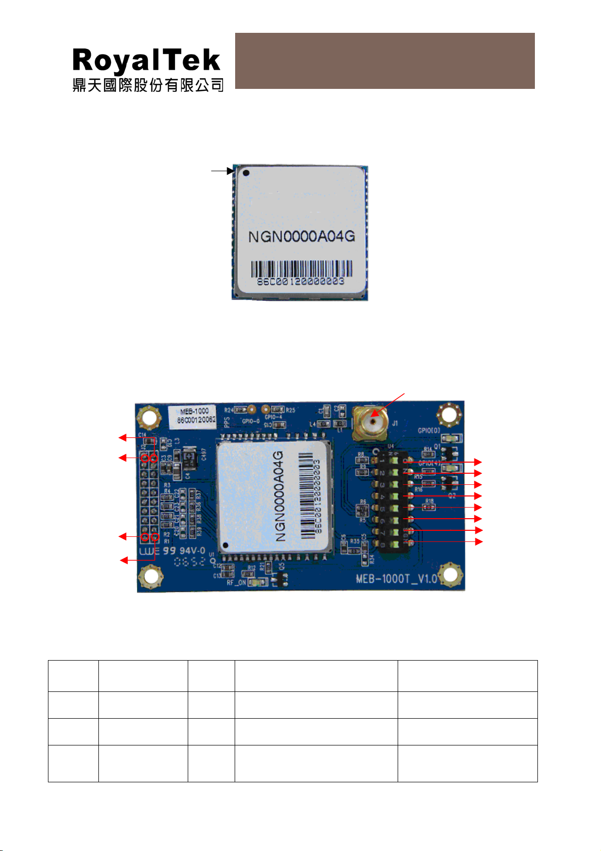
1.3 Product Pictures
+
(1) MEB-1000
pin1
(2) MEB-1000 Interface board
MEB-1000 User Manual
Figure 1 MEB-1000 Picture
SMARF connector (J1)
J2 CONNECTOR
U4
Pin 1
Pin 2
Pin 3
Pin 4
Pin 19
Pin 20
Pin 5
Figure 2 MEB-1000 Interface Board
1.4 The interface Board Pin Definition
Table 1-1 J2 Connector
Pin # Signal Name I/O Description Characteristics
1
2
3
ANTPWR I DC Supply Voltage Output
NC
VBAT I RTC Backup Battery
Supply
2
3.3V±5%
3.6V~1.6 DC +
Page 7
MEB-1000 User Manual
4
5
6
7
8
9
10
11
12
13
14
15
16
17
18
19
VCC I DC Supply Voltage Output
Reset I External Reset Signal
NC
NC
NC
NC
NC
TX0 O Serial Port 0
RX0 I Serial Port 0
NC
TX1 O Serial Port 1
RX1 I Serial Port 1
NC
NC
GND G Reference Ground
Time Mark O One pulse per second
3.3V±5%
20
GND G Reference Ground
Table 1-2 Switch U4
Pin # Signal Name 0/1 Description Characteristics
1
2
3
4
5
6
GPIO-0 GPIO input/output Switch:
0:Low 1:High CMOS
TTL Level
GPIO-4 GPIO input/output Switch:
0:Low 1:High CMOS
TTL Level
N.C
N.C
GPS_3V3 Power supply for GPS section Switch:
N.C
0:Low 1: DC 3.3V
output
7
8
N.C
RF_Bias RF_Bias voltage switch 0: open. No voltage
3
provide antenna.
1:Provide 2.85V to
Page 8

MEB-1000 User Manual
Table 1-3 Connector:
Pin # Description Characteristics
antenna.
J1
GPS RF Connector 1575.42MHz
1.5 RoyalTek Evaluation Kit MEV-1000 for MEB-1000
(Please refer to RoyalTek Evaluation Kit MEV-1000 for MEB-1000 Operational Manual for
more information)
4
Page 9

MEB-1000 User Manual
1.6 MEB-1000 System Block Diagram
System block diagram description:
(1) External antenna.
(2) 4 Mega bits flash memory
(3) 31 pin I/O pin
Antenna
Figure 3 Block Diagram
1.7 MEB-1000 Technical Specification
Impedance:50Ω
No Function Specification
GPS receiver
Chipset
1
Frequency L1 1575.42MHz.
2
Code C.A. Code.
3
Channels 32
4
Sensitivity (Acquisition)
5
Cold start 36 sec (open sky)
6
Warm start 35 sec (open sky)
7
Hot start 1 sec (open sky)
8
MediaTek MT3179 (RF )& MT3301 (Digital)
-130dBm.
5
Page 10

MEB-1000 User Manual
Reacquisition < 1sec
9
Position accuracy 3 meters 2D RMS(w/o aid)
10
Maximum altitude 18000 m
11
Maximum velocity 515 m/s
12
Trickle power mode N/A
13
Update rate 1Hz
14
Testability N/A
15
Protocol setup
16
DGPS 1.WAAS, EGNOS
17
Interface
LNA No LNA
18
I/O Pin 31pin
19
Mechanical requirements
Weight
20
Power consumption
Vcc DC 3.3 ±5%
21
Current
22
Environment
Operating temperature
23
Storage temperature
24
It can store the protocol setup in the SRAM and Flash memory.
2.RTCM protocol
≦3.5g
GPS :
< 65mA@3.3V (ACQ w/o ext. Antenna)
< 40mA@3.3V (Tracking w/o ext. Antenna)
-30 ~ 85℃
-40 ~ 85℃
6
Page 11

1.8 Application Circuit
MEB-1000 User Manual
Note:
(1) Serial Interface:
(Ⅰ)The TXA & RXA pin is recommended to connect to serial resistance(220
(Ⅱ)The TXB & RXB pin is recommended to connect to serial resistance(220
(2) Backup Battery:
It’s recommended to connect a backup battery to V_RTC_3V3.
In order to enable the warm start and hot start features of the GPS receiver.
If you don’t intend to use a backup battery, connect this pin to GND or open.
If you use backup battery, should be add a bypassing capacitor (10uF) at
V_RTC_3V3 pin. It can reduce noise and increase the stability.
(3) GPS_RF_IN:
Figure 4 Application Circuit
Ω) and pull up (10KΩ). It can increase the stability of serial data.
Ω) and pull up (10KΩ), if use the DGPS output.
If no use DGPS output, it don’t connect anything.
Connecting to the antenna has to be routed on the PCB. The transmission
line must to controlled impedance to connect RF_IN to the antenna or
antenna connector of your choice. (Impedance 50Ω)
(4) Power:
Connect V_GPS_3V3 pin to DC 3.3V. The power supply must add bypassing
7
Page 12

MEB-1000 User Manual
capacitor(10uF and 1uF).It can reduce the Noise from power supply and
increase power stability.
(5) Active antenna bias voltage:
The Vcc_RF_OUT pin(pin 20) is provide voltage 2.85V. If you use active
antenna, you can connect this pin to V_ANT_IN pin (pin 19) to provide bias
voltage of active antenna. The bias voltage will be through GPS_RF_IN pin
to provide active antenna bias voltage from Vcc_RF_OUT pin.
If your bias voltage of active antenna isn’t 2.85V, you can input bias voltage
to V_ANT_IN pin (pin 19).And input bias voltage of you need. The input bias
voltage will through GPS_RF_IN pin to provide active antenna bias voltage
from V_ANT_IN pin.
PS:
(1) The maximum power consumption of active antenna is about 100mW.
(2) Suggest input gain > 20dB,and NF < 1.5 dB 。
(6) GPIO:
The GPIO pin is recommended to connect to serial resistance(220Ω),if use
the GPIO function.
If no use GPIO function, it don’t connect anything.
8
Page 13

1.9 Recommended Layout PAD
MEB-1000 User Manual
TOP View
Figure 5 Recommended Layout Pad
9
Page 14

1.10 Mechanical Layout
MEB-1000 User Manual
P17
P31
Figure 6 Mechanical Layout
1.11 Hardware Interface
Interface Pin Number:
P16
P1
Unit:mm
10
Page 15

MEB-1000 User Manual
=
Figure 7 Interface Pin Number
Table 1-4 Pin Definition
Pin # Signal Name I/O Description Characteristics
1 V_GPS_3V3 I DC Supply
Voltage input
2 GND G Ground Reference Ground
3 N.C
4 RXA I Serial port A
5 TXA O Serial port A
6 TXB O Serial port B
7 RXB I Serial port B
8 N.C
9 RF_ON O Indicates power
state of RF part
DC +3.3V±5%
VVVVV
8.00.3V- 26.3 ≤≤≥≥
ILIH
VVVVV
OLOH
OLOH
VVVV
0 85.2 =
OLOH
4.00.3V- 4.215.3 ≤≤≥≥
VVVVV
4.00.3V- 4.215.3 ≤≤≥≥
VVVVV
8.00.3V- 26.3 ≤≤≥≥
ILIH
10 GND G Ground Reference Ground
11 N.C
12 N.C
13 GND G Ground Reference Ground
11
Page 16

MEB-1000 User Manual
±
=
+
+
14 N.C
15 GND G Ground Reference Ground
16 GND G Ground Reference Ground
17 GPS_RF_IN I GPS Signal input 50 Ω @1.57542GHz
18 GND G Ground Reference Ground
19 V_ANT_IN I Active Antenna
20 VCC_RF_OUT O Supply Antenna
21 V_RTC_3V3 I Backup voltage
22 Reset I Reset (Active
23 N.C
24 N.C
25 GPIO4 I/O General purpose
26 GPIO0 I/O General purpose
27 N.C
Bias voltage
Bias voltage
supply
low)
I/O
I/O
Receiving DC power supply for active
antenna bias.
%585.2
O
Current<35mA
VV
10uACurrent
≤
3.6V~1.6 DC
VVVVV
8.00.3V- 26.3 ≤≤≥≥
ILIH
VVVVV
8.00.3V- 26.3 ≤≤≥≥
ILIH
VVVVV
OLOH
OLOH
4.00.3V- 4.215.3 ≤≤≥≥
VVVVV
8.00.3V- 26.3 ≤≤≥≥
ILIH
VVVVV
4.00.3V- 4.215.3 ≤≤≥≥
28 N.C
29 PPS O One pulse per
second
30 GND G Ground Reference Ground
31 N.C
V_GPS_3V3(+3.3V DC power Input)
This is the DC power supply input pin for GPS system. It provides voltage
to module.
GND
GND provides the ground .
RXA
This is the main receiver channel and is used to receive software
commands to the board from PowerGPS software or from user written
VVVVV
OLOH
4.00.3V- 4.215.3 ≤≤≥≥
12
Page 17

MEB-1000 User Manual
software.
RXB
This is the auxiliary receiving channel and is used to input differential
corrections to the board to enable DGPS navigation.(Option)
TXA
This is the main transmitting channel and is used to output navigation and
measurement data to PowerGPS or user written software.
TXB
For user’s application (not currently used).
RF_ON
This pin indicates state of RF voltage.
GPS_RF_IN
This pin receives GPS analog signal. The line on the PCB between the
antenna(or antenna connector) has to be a controlled impedance line
(Microstrip at 50Ω).
V_ANT_IN
This pin is reserved as external DC power supply input for active antenna.
If using 2.85V active antenna, pin 20 has to be connected to pin 19.
If using 3.3V or 5V active antenna ,this pin has to be connected to 3.3V or
5V power supply.
PS: The current must be ≦100mA and voltage ≦12V,if using external
power supply.
VCC_RF_OUT
This pin can provide power 35mA@2.85V for active antenna.
Reset
This pin provides an active-low reset input to the board. It causes the board
to reset and start searching for satellites. If not utilized, it may be left open.
PPS
This pin provides one pulse-per-second output from the board, which is
synchronized to GPS time. This is not available in Trickle Power mode.
V_RTC_3V3 (Backup battery )
This is the battery backup input that powers the SRAM and RTC when
main power is removed. Typical current draw is 10uA.
The supply voltage should be between 1.6V and 3.6V.
GPIO Functions
13
Page 18

MEB-1000 User Manual
Several I/Os are connected to the digital interface connector for custom
applications.
14
Page 19

MEB-1000 User Manual
2 Software Interface
2.1 NMEA V3.1 Protocol
Its output signal level is TTL: 4800 bps (default), 8 bit data, 1 stop bit and no parity. It supports
the following NMEA-0183
Messages: GGA, GSA, GSV, RMC .
NMEA Output Messages: the Engine board outputs the following messages as shown in
Below:
Table 2-1 NMEA-0183 Output Messages
NMEA Record Description
GGA Global positioning system fixed data
GSA GNSS DOP and active satellites
GSV GNSS satellites in view
RMC Recommended minimum specific GNSS data
GGA-Global Positioning System Fixed Data
Below table contains the values of the following example:
$GPGGA, 161229.487, 3723.2475, N, 12158.3416, W, 1, 07, 1.0, 9.0, M, , , ,0000*18
Table 2-2 GGA Data Format
Name Example Units Description
Message ID $GPGGA GGA protocol header
UTC Position 161229.48
7
Latitude 3723.2475 ddmm.mmmm
N/S Indicator N N=north or S=south
Longitude 12158.341
6
E/W Indicator W E=east or W=west
Position Fix Indicator 1 See Table 2-1
hhmmss.sss
Dddmm.mmmm
Satellites Used 07 Range 0 to 12
HDOP 1.0 Horizontal Dilution of
Precision
MSL Altitude 9.0 meters
Units M meters
Geoid Separation meters
15
Page 20

MEB-1000 User Manual
Units M meters
Age of Diff. Corr. second
Diff. Ref. Station ID 0000
Checksum *18
Null fields when DGPS is not
used
<CR><LF>
End of message termination
Table 2-3 Position Fix Indicators
Value Description
0 Fix not available or invalid
1 GPS SPS Mode, fix valid
2 Differential GPS, SPS Mode, fix valid
3-5 Not Supported GPS PPS Mode, fix valid
6 Dead Reckoning Mode, fix valid
GSA-GNSS DOP and Active Satellites
Below table contains the values of the following example:
$GPGSA, A, 3, 07, 02, 26, 27, 09, 04, 15, , , , , , 1.8,1.0,1.5*33
Table 2-4 GSA Data Format
Name Example Units Description
Message ID $GPGSA GSA protocol header
Mode 1 A See Table 4-2
Mode 2 3 See Table 4-1
Satellite Used 07 Sv on Channel 1
Satellite Used 02 Sv on Channel 2
…. ….
Satellite Used Sv on Channel 12
PDOP 1.8 Position Dilution of Precision
HDOP 1.0 Horizontal Dilution of Precision
VDOP 1.5 Vertical Dilution of Precision
Checksum *33
<CR><LF>
End of message termination
Table 2-5 Mode 1
Value Description
1 Fix not available
2 2D
16
Page 21

MEB-1000 User Manual
3 3D
Table 2-6 Mode 2
Value Description
M Manual-forced to operate in 2D or 3D mode
A Automatic-allowed to automatically switch 2D/3D
GSV-GNSS Satellites in View
Below table contains the values of the following example:
$GPGSV, 2, 1, 07, 07, 79, 048, 42, 02, 51, 062, 43, 26, 36, 256, 42, 27, 27, 138,
42*71$GPGSV, 2, 2, 07, 09, 23, 313, 42, 04, 19, 159, 41, 15, 12, 041, 42*41
Table 2-7 GGA Data Format
Name Example Units Description
Message ID $GPGSV GSV protocol header
Number of
Messages
Messages
Number
Satellites in View 07
Satellite ID 07 Channel 1(Range 1 to 32)
Elevation 79 degrees Channel 1(Maximum 90)
Azimuth 048 degrees Channel 1(True, Range 0 to 359)
SNR (C/No) 42 dBHz Range 0 to 99, null when not tracking
…. ….
Satellite ID 27 Channel 4(Range 1 to 32)
Elevation 27 degrees Channel 4(Maximum 90)
Azimuth 138 degrees Channel 4(True, Range 0 to 359)
SNR (C/No) 42 dBHz Range 0 to 99, null when not tracking
Checksum *71
1
1
2 Range 1 to 3
1 Range 1 to 3
<CR><LF>
1
Depending on the number of satellites tracked multiple messages of GSV data may be
required.
RMC-Recommended Minimum Specific GNSS Data
Below table contains the values of the following example:
$GPRMC, 161229.487, A, 3723.2475, N, 12158.3416, W, 0.13, 309.62, 120598, ,*10
End of message termination
17
Page 22

MEB-1000 User Manual
Table 2-8 GGA Data Format
Name Example Units Description
Message ID $GPRMC RMC protocol header
UTC Position 161229.487 hhmmss.sss
Status A A=data valid or V=data not valid
Latitude 3723.2475 ddmm.mmmm
N/S Indicator N N=north or S=south
Longitude 12158.3416 dddmm.mmmm
E/W Indicator W E=east or W=west
Speed Over Ground 0.13 knots
Course Over
Ground
Date 120598 ddmmyy
Magnetic Variation degrees E=east or W=west
Mode A A=Autonomous, D=DGPS, E=DR
Checksum *10
309.62 degrees True
18
Page 23

p
3 RoHS Reflow Diagram
MEB-1000 User Manual
260oC,10sec max
Critical Zone
T
to T
L
P
Tem
erature
o
o
o
o
T
P
T
L
Ts
max
20~40sec
Ramp-up
o
C/sec max
3
60~150sec
Ramp-down
o
C/sec
6
o
Ts
min
Ts Pretest
60~180sec
T25oC to peak,480 sec max
Time
Figure 8 RoHS Reflow Diagram
19
Page 24

MEB-1000 User Manual
4 Package Specification and Order Information
Shipment Method: Tape and reel
SMT type with stamp holes (31 holes)
Figure 9 Tape & Reel Packaging Information
20
Page 25

MEB-1000 User Manual
5 Contact Information
Contact: sales@royaltek.com
Headquarter:
Address: 8F, 256 Yang Guang Street, Neihu Chiu, Taipei, Taiwan
Tel: 886-2-77215000
Fax: 886-277215666
Web Site: http://www.royaltek.com
Web Site Customer Service: http://www.royaltek.com/contact
6 Revision History
Title MEB-1000 GPS Receiver Module
Doc Type User Manual
Revision
Number
1.0 2007/05/25 Amy Liu Initial Release
Date Author Change notice
21
 Loading...