

Page 1
MODEL: RSL-2701
www.royalsovereign.com
RSL-2701U
RSL-380
ROLL LAMINATOR SERVICE MANUAL
Page 2

3 ~ 3
4 ~ 10
4 ~ 6
6 ~ 7
8 ~ 9
9 ~ 10
11 ~ 11
12 ~ 18
12 ~ 12
13 ~ 13
13 ~ 14
14 ~ 14
15 ~ 15
15 ~ 16
16 ~ 17
17 ~ 18
19 ~ 19
20 ~ 23
24 ~ 34
35 ~ 38
4.Adjustments
……………………………………………………………………………………
3.8) Replacement of Motor………………………………………………………………………
5. Parts List
…………………………………………………………………………………………
2
6.Exploded Drawings ………………………………………………………………………
7.Wire Diagram …………………………………………………………………………………
3.4) Main PCB ……………………………………………………………………………………………
3.5) Sub PCB ………………………………………………………………………………………………
3.6) Heaters ………………………………………………………………………………………………
3.7) Cross Cutter …………………………………………………………………………………………
3.Replacing Parts ………………………………………………………………………………
3.1) Right Cover …………………………………………………………………………………………
3.2) Left Cover …………………………………………………………………………………………
3.3) Rear Cover …………………………………………………………………………………………
Table of Content
1.Safety Precautions
………………………………………………………………………
2.Troubleshooting ……………………………………………………………………………
2.5) Poor Lamination Quality …………………………………………………………………………
2.1) Rollers Not Heating ………………………………………………………………………………
2.2) Rollers Over Heating ……………………………………………………………………………
2.3) Rollers Not Running ………………………………………………………………………………
2.4) No Main Power ……………………………………………………………………………………
Page 3
1. Safety Precautions
3
Failure to comply any of the following safety procedures could result in
1. Only a licensed electrician should install wiring and outlet for the laminator.
serious injury. Please read the instructions carefully and keep for future
reference.
2. Ensure the unit is plugged into a properly grounded outlet with the correct
voltage.
3. Keep hands and clothing (ie. Neckties) away from rollers. The rollers are
pinch points that can trap body parts or clothing and cause serious injury .
4. Keep flammable and wet objects away from the machine .
5. Place machine on a level surface.
6. Avoid excessive sunlight, humidity and extreme temperatures.
7. Ensure the unit is turned off, cooled ,and unplugged from the outlet prior to
moving and/or repairing.
8. Keep out of reach of children.
9. Only Royal Sovereign authorized maintenance and service technicians should
make repairs.
10. Do not attempt to laminate items that exceed total recommended material
thickness for the unit.
11. When cleaning the machine, don't use flammable sprays or materials.
12. Do not touch the rollers when they are hot or place foreign objects inside the
machine.
13. Do not cover the surface of the machine until the machine has completely
colled.
3
Page 4

4
Page 5
2.1 Rollers Not Heating
disconnected with MAIN PCB.(except RSL-380)
2. Troubleshooting
CAUSES
MEASURES
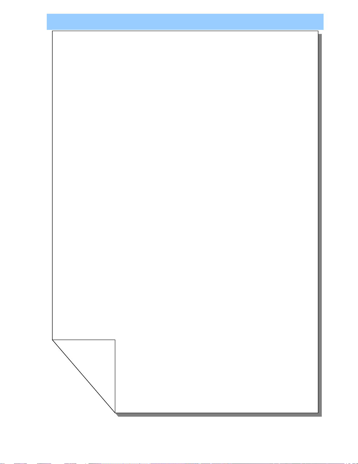
1. The wire connector from the heater is
1. The wire connector from the heater is disconnected
with MAIN PCB.(except RSL-380)
2. The Wire-Temp Fuse is disconnected.
3. The Main Fuse is defective.(except RSL-380)
4. The Bi-metal is defective.
5. The heater in the roller is defective.
6. Main PCB is defective.
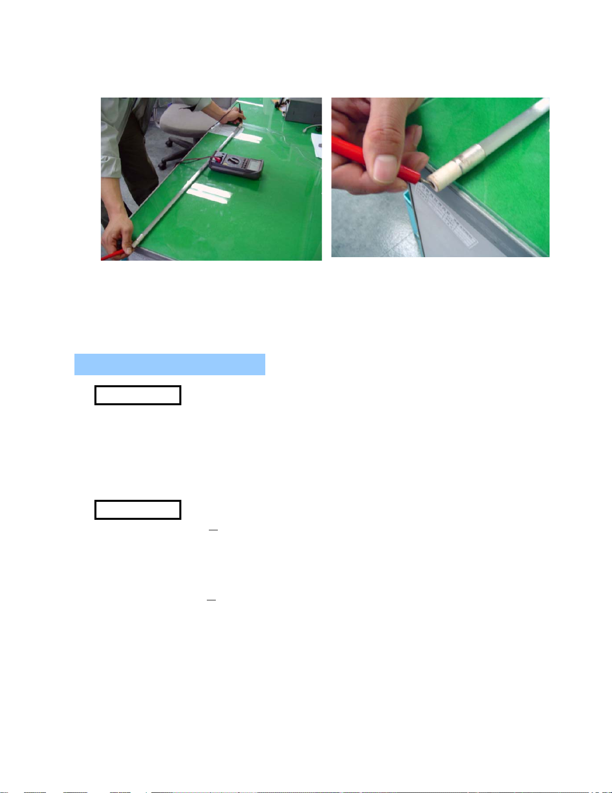
Before troubleshooting, be sure to
disassemble the Right cover ,
the Left cover and the Frame Rear.
Refer to how to replace each component
for the disassembly of them.
1) Test if the connector wire is
disconnected with Multi-tester.
2) If disconnected, replace it with
new one.
WIRE-
HEATER
4
Page 6
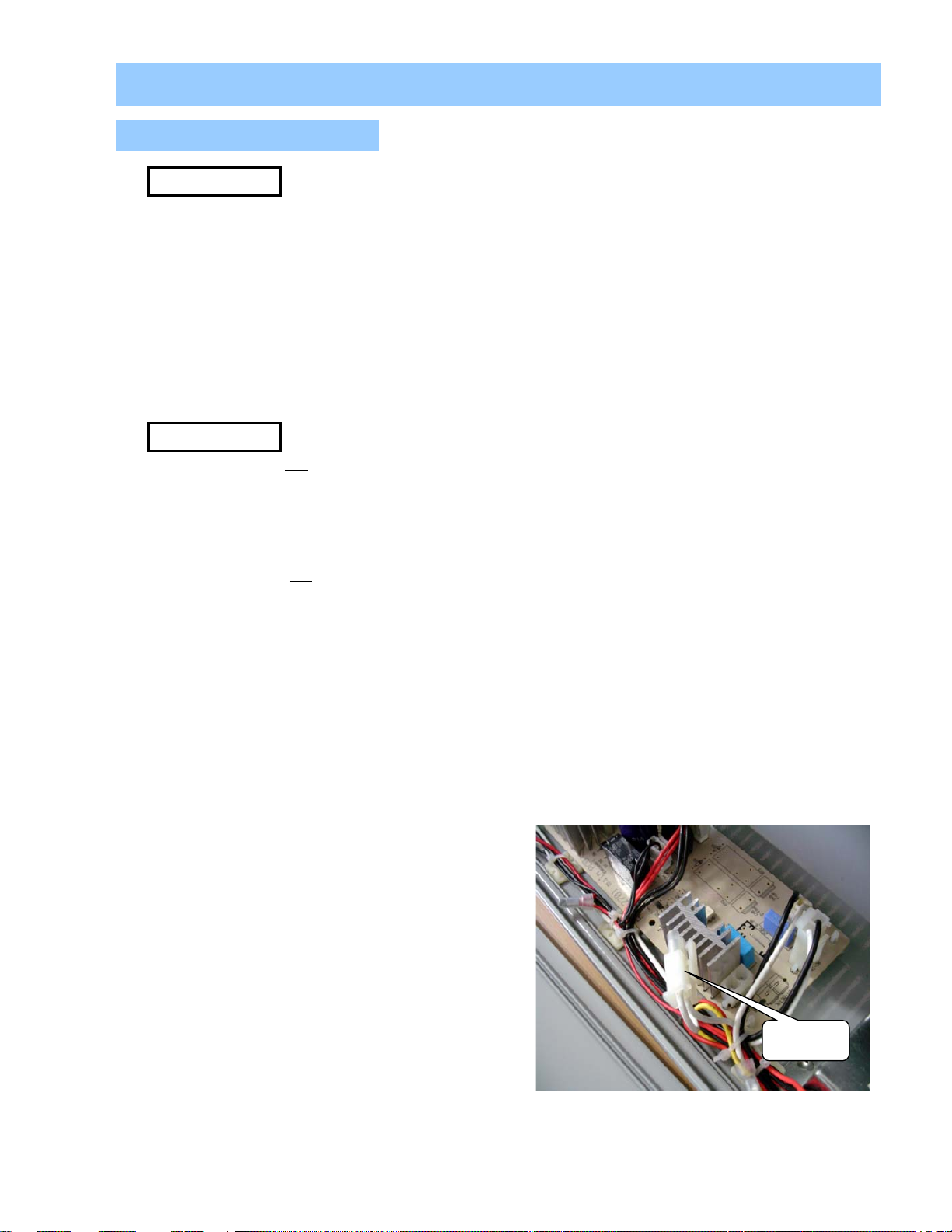
2 The Wire-Temp Fuse is disconnected
1) Test if the Wire-Temp Fuse is disconnected with Multi-tester.
3. MAIN FUSE is disconnected.(except RSL-380)
4. The Bi-metal is defective.
2) If disconnected, replace it with new one.
1) Test if the Main Fuse is disconnected with Multi-tester.
2) If disconnected, replace it with new one.
WIRE-TEMP FUSE
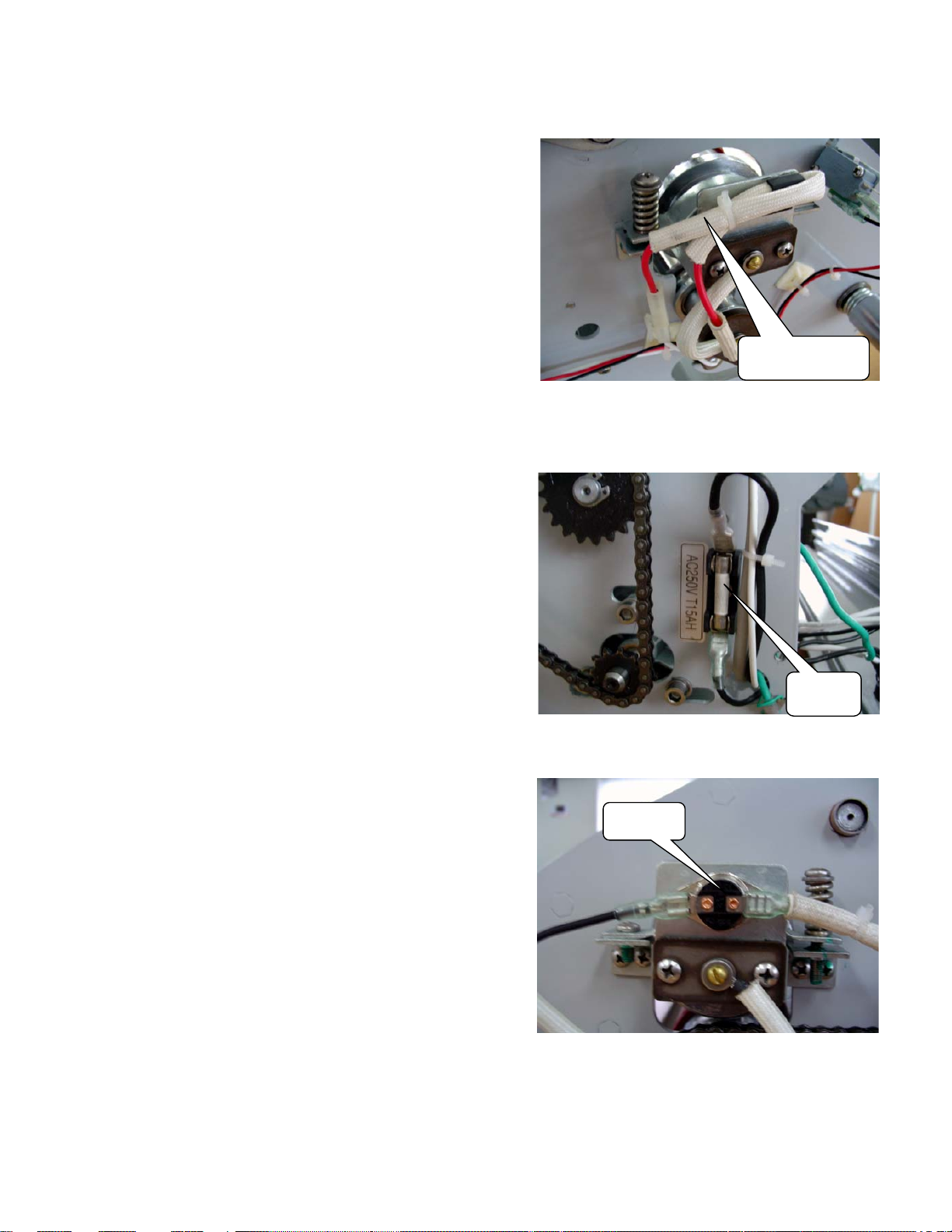
1) Disconnect the heater wire from the Bi-metal.
2) Unfasten 2 screws holding the Bi-metal.
3) Replace it with new one.
5
MAIN
FUSE
BI-METAL
Page 7
5. The heater in the roller is defective.
1) Test if the heater is disconnected with Multi-tester.
2.2 Rollers Not Heating
the Right cover , the Left cover and the Frame
MEASURES
CAUSES
6
6. Main PCB is defective.
2) If disconnected, replace it with new one.
Replace Main PCB with new one according to How to replace Main PCB
only when all of the above mentioned heater wire, wire thermal fuse,
heater and Bi-metal are normal.
1. The Temperature Sensor is not work.
2. The wire thermal fuse is defective.
3. The heater in the roller is defective.
4. Main PCB is defective.
Before trouble shooting, be sure to disassemble
Rear.
Refer to how to replace each component for the
disassembly of them.
Page 8
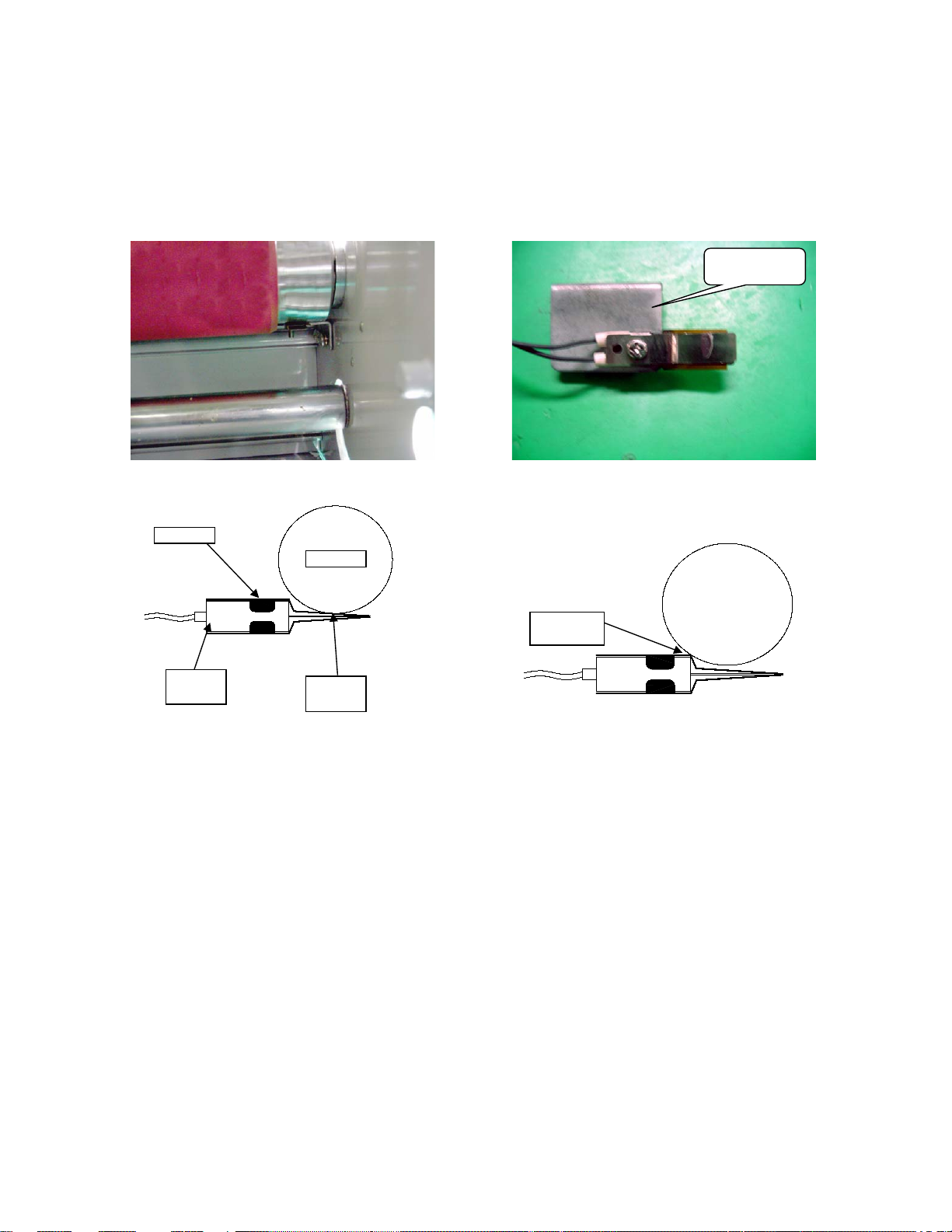
1) Disassemble the Right cover. (Refer to how to replace Cover-R.)
4. Main PCB is defective.
<The Proper position>
<The wrong position>
1. The Temperature Sensor is not work.
<Sensor Ass'y position>
<Sensor Ass'y>
RSL-380
2. The wire thermal fuse is defective.
3. The heater in the roller is defective.
2) Disassemble the Bracket-Sensor with Sensor ass'y.
Test if the Sensor ass'y is disconnected with Multi-tester.
Again, Attach The Bracket-Sensor as the proper position.
Sensor
Roller
Bracket-Sensor
Contact
position
Temp.
Sensor
1) Test if the wire thermal fuse is disconnected with Multi-tester.
Contact
position
2) If disconnected, replace it with new one.
1) Test if the heater is disconnected with Multi-tester.
2) If disconnected, replace it with new one.
1) Replace Main PCB with new one according to How to replace Main PCB
only when all of the above mentioned heater wire, wire thermal fuse,
heater and Bi-metal are normal.
7-1
Page 9
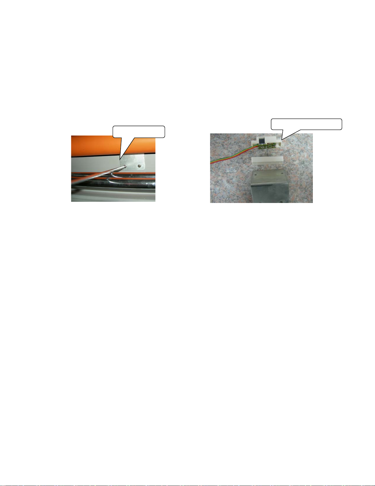
1) Disassemble the Right and the Left cover. (Refer to how to replace Cover.)
2) If disconnected, replace it with new one.
only when all of the above mentioned heater wire, wire thermal fuse,
2. The wire thermal fuse is defective.
3. The heater in the roller is defective.
4. Main PCB is defective.
<Sensor Ass'y position>
<Sensor Ass'y>
RSL-2701,RSL-2701U
1. The Temperature Sensor is not work.
2) Disassemble the Bracket-Sensor with Sensor ass'y.
Test if the Sensor ass'y is disconnected with Multi-tester.
BRACKET SENSOR
SENSOR ASS'Y
1) Test if the wire thermal fuse is disconnected with Multi-tester.
1) Test if the heater is disconnected with Multi-tester.
2) If disconnected, replace it with new one.
1) Replace Main PCB with new one according to How to replace Main PCB
heater and Bi-metal are normal.
7-2
Page 10
2.3 Rollers Not Running
1. Safety cover is not in proper position.
CAUSES
8
2. Motor wire connectors are disconnected.
MEASURES
1. Safety cover is not in proper position.
2. Wire-Motor's connector is disconnected.
3. Film is jammed on the rollers.
4. Main PCB is defective.
5. Main motor is defective.
Before troubleshooting, be sure to disassemble
the Right cover ,the Left cover and the Rear cover.
Refer to how to replace each component for the
disassembly of them.
1) Make the edge of Safety Cover to press
the lever of Micro Switch completely.
Check if the Motor wire connectors are
connected correctly.
edge of safety cover
MICRO
SWITCH
WIRE-
MOTOR
Page 11
3. Film is jammed on the rollers.
1) First press reverse button.
4. Main PCB is defective
5. Replace Motor with new one according to How to replace the Motor.
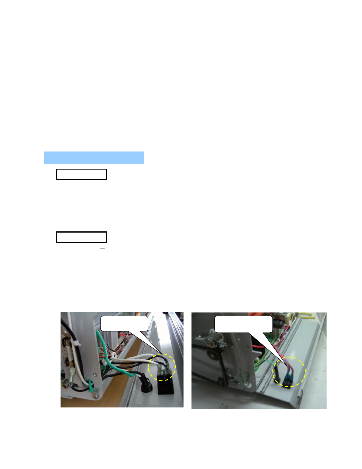
2.4 No Main Power
1. Main power wire is not connected with Main Switch.
<RSL-2701/2701U>
<RSL-380>
9
MEASURES
CAUSES
2) Pull jammed film slowly to the back of the machine.
3) If you feel film is jammed again, stop pressing reverse button.
4) press run button, and then pull jammed film to the back of the machine.
Replace Main PCB with new one according to How to replace Main PCB
only when all of the above mentioned Emergency switch, Frame paper guide,
Safety cover switch, motor wire connectors, main motor and film are normal.
1. Main power wire is not connected with Main Switch
2. Main fuse is disconnected.(except RSL-380)
3. Wire-AC IN is not connected with Main PCB.(except RSL-380)
4. Transformer is defective.
Before troubleshooting, be sure to disassemble the Right cover ,
the Left cover and the FRAME Rear.
Refer to how to replace each component for the
disassembly of them.
1) Check if the Main power wires are connected correctly.
MAIN SWITCH
MAIN SWITCH
connecting part
Page 12
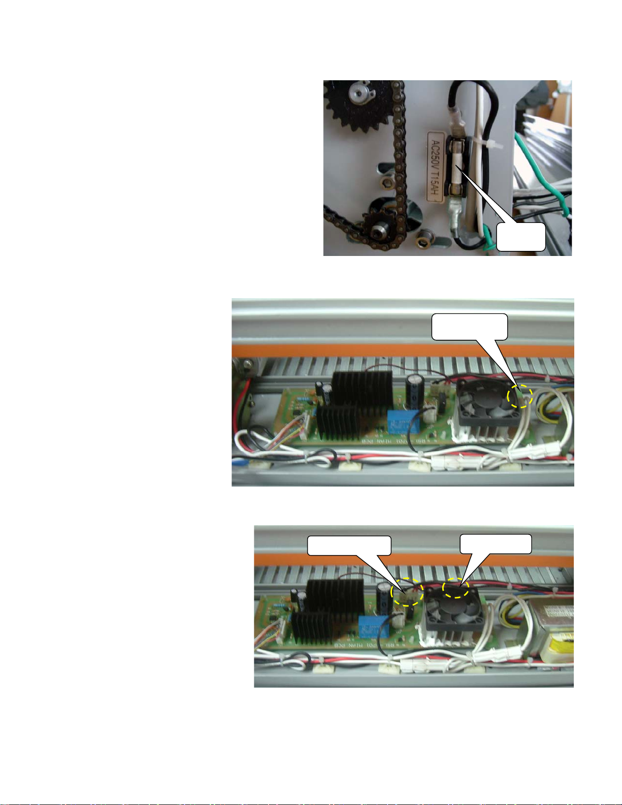
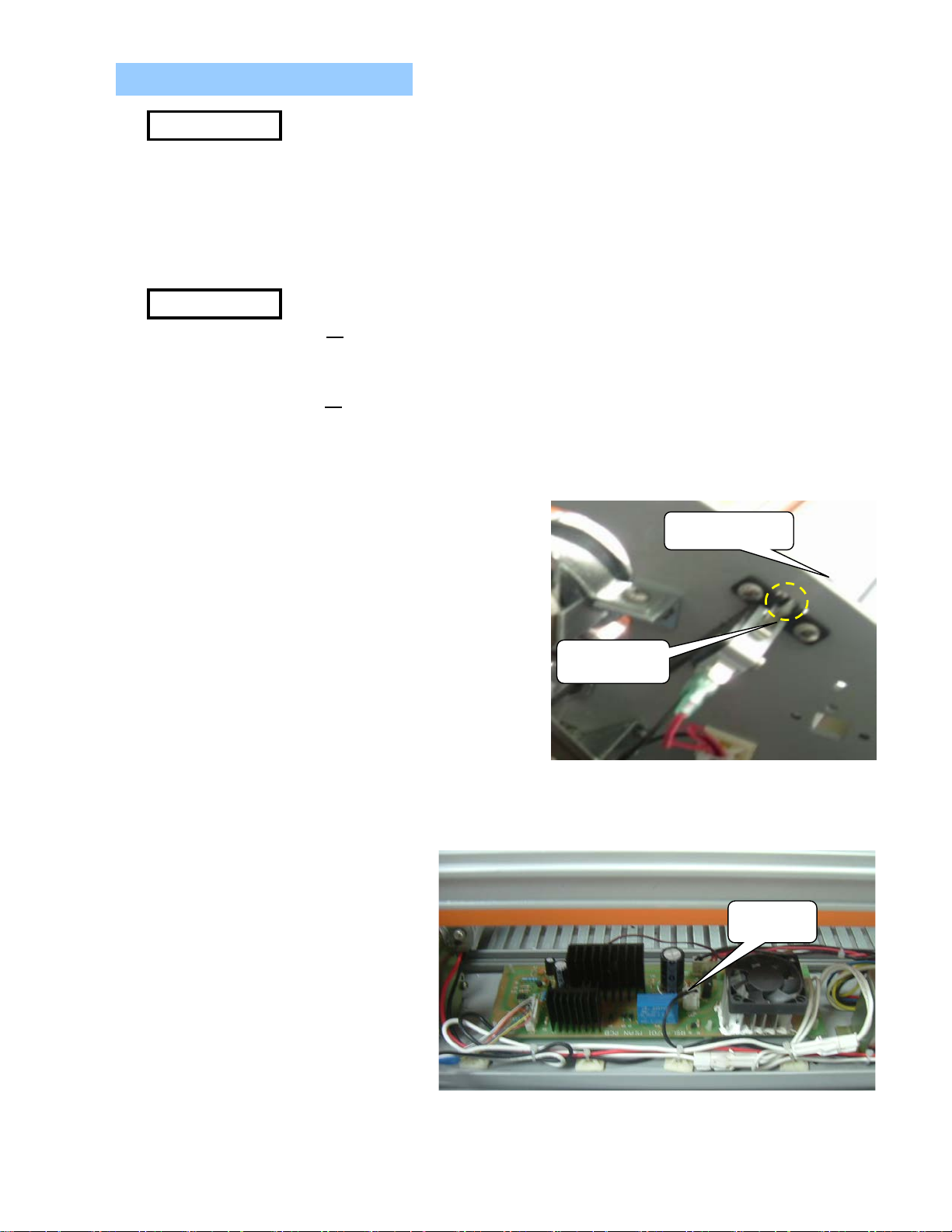
2. Main fuse is disconnected.(except RSL-380)
1) Test if the main fuse is disconnected with Multi-tester.
3. Wire-AC IN is not connected with Main PCB.(except RSL-380)
4. Transformer is defective.
10
2) If disconnected, replace it wit new
one.
1) Check if the Wire-AC IN are connected correctly.
MAIN
FUSE
WIRE-AC IN
1) Unfasten two screws.
2) Separate 2 connectors.
3) Detach transformer.
4) Replace it with new one.
TRANS. OUT
TRANS. IN
Page 13
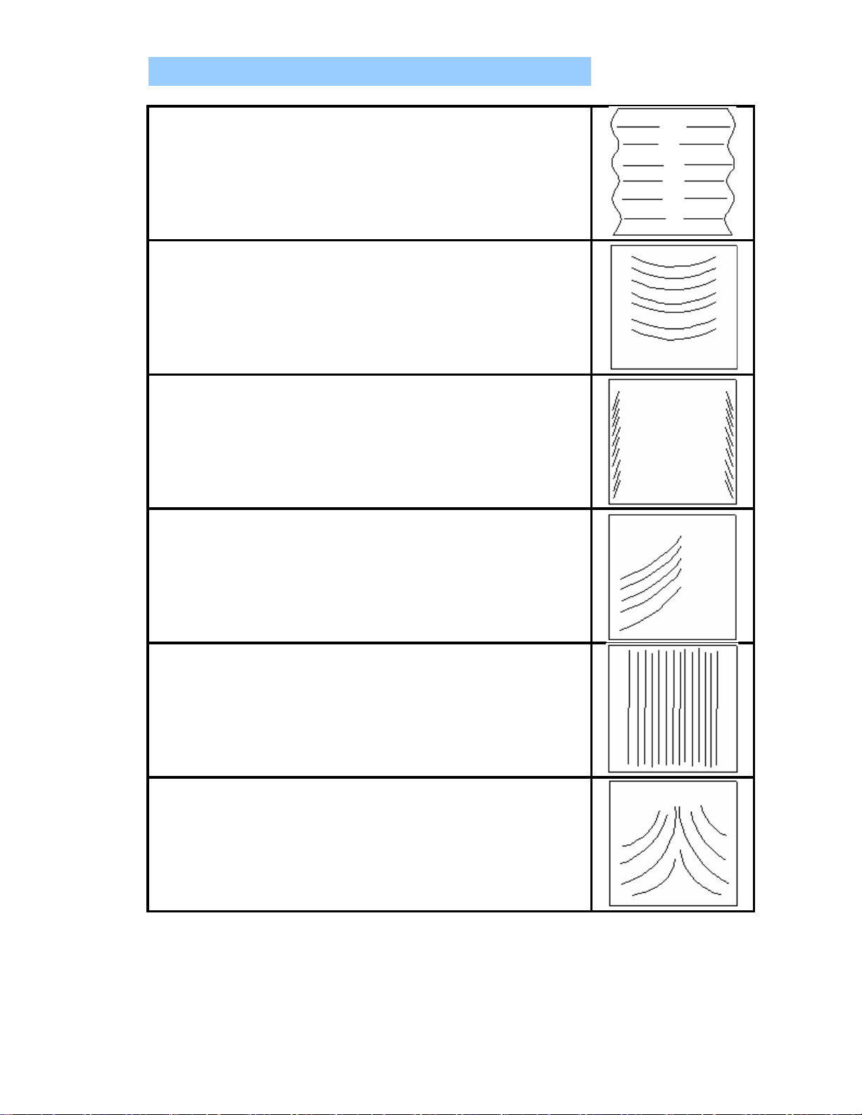
2.5 Poor Lamination Quality
Problem: Straight wave lines across the output.
Cause: Excessive front roller pressure.
Measure:
Problem: Concave waves in the lamination.
Cause: Excessive rear (pulling) roller pressure.
Measure:
Problem: Angled waves on both sides of the output.
Cause: Insufficient rear roller pressure.
Measure:
Problem: Angled waves on one side of the output.
Cause: Insufficient rear left (or right) side roller pressure.
Measure:
Problem: Straight waves in the output.
Cause: Excessive heat at the nip rollers.
Measure: Lower the roller temperature.
Problem: Wake waves.
Cause: Insufficient heat at the nip rollers.
Measure:
Loosen the front roller pressure.
Loosen the rear back roller pressure.
Tighten the rear roller pressure.
Tighten the rear left (or right) side roller pressure.
Raise the roller temperature.
11
13
Page 14

3.1. Right Cover
<RSL-2701/2701U> <RSL-380>
and detach the Sub-PCB.
Caution :
3. Replacing Parts
Turn off the switch of the machine and then
pull out the power cord plug from the electrical outlet.
1) Unfasten 4 screws holding the Right
cover and disassemble the Right cover.
2) Pull out the male connector from the Sub-PCB .
3) Unfasten 4 screws holding the Sub-PCB
4) How to assemble is the reverse order of how
to disassemble , 3)→2)→1).
12
Page 15

3.2. Left Cover
3.3. Rear Cover
1) Unfasten 2 nuts holding the Knob Tension
2) disassemble the Knob-Tension.
3) Unfasten 4 screws holding the Left cover
and disassemble the Left cover .
1) Disassemble both the Right cover and the Left cover.
2) Unfasten 4 screws holding the Rear cover (right and left) .
13
Page 16

3.4. Main PCB
order of how to disassemble ,2)→1).
3) Disassemble Wire connect to MAIN S/W,
POWER CORD.
4) Disassemble MAIN S/W and POWER CORD.
5) How to assemble is the reverse order of how to disassemble , 4)→3)→2)→1).
1) Pull out all the connectors from the main PCB.
2) Detach the main PCB from
4 white plastic supporters.
3) How to assemble is the reverse
PCB SUPPORT
14
Page 17

3.5. Sub PCB
3.6. Heaters
2) Unfasten 2 screws holding the heater and disassemble the wire.
< Detachment 2 screws holding the heater>
3) Unfasten 2 screws and disassemble the bracket holding the lower heater.
< Detachment of Bracket-Heater>
1) Refer to No 1.(Replacement of cover-R)
1) Disassemble both the Right cover and the Left cover (Refer to No.1, No.2) .
15
Page 18

4) Disassemble the Bush-Roller, Up holding the upper heater.
< Take off Bush-Roller, Up from Laminating Roller >
3.7. Cross Cutter
<RSL-2701/2701U> <RSL-380>
5) Disassemble the lower and upper heater from the roller cautiously
6) How to assemble is the reverse order of how to disassemble , 5)→4)→3)→2)→1).
When inserting the heater into the roller, rotate the heater slightly
and the heater enter the roller smoothly.
1) Disassemble both the Right cover and the Left cover (Refer to No.1, No.2) .
2)a. Unfasten 6 screws holding the Frame-Upper.(RSL-2701/2701U)
b. Unfasten 1 screw on the Frame-cutter.(RSL-380)
16
Page 19

3)a. Disassemble Frame upper with Cross Cutter.(RSL-2701/2701U)
<RSL-380>
<RSL-2701/2701U>
3.8. Replacement of MOTOR
b. Disassemble Cross Cutter from the Frame-Cutter.(RSL-380)
4) Disassemble the Cross Cutter from the Frame-Upper.(RSL-2701/2701U)
5)a. How to assemble is the reverse order of how to
disassemble , 4)→3)→2)→1).(RSL-2701/2701U)
b. How to assemble is the reverse order of how to
disassemble , 3)→2)→1).(RSL-380)
1) Disassemble the Right cover , the Left
cover and the frame rear
2) unfasten the screw (PULLEY-CHAIN)
17
Page 20

3) unfasten the set screw (sprocket motor)
18
4) take out the sprocket motor from the motor
5) unfasten the three screws from the motor
6) detach the connector and change the motor
7) How to assemble is the reverse order of how
to disassemble , 6)→5)→4)→3)→2)→1).
Page 21

Adjusting Front and Rear Roller
19
5.
Check above steps 2 through 4
4
.Laminating Test
–
rollers should be 5~7.
2.
Checking for over all tension
3.
Pressure mark checking (Heat Line)
4. Adjustments
1.
Using Push-Pull Scale
Pressure
•
Use Screwdriver
to adjust the roller pressure:
C.W – Increase pressure.
C.C.W – Decrease pressure.
, measure
5 spots as shown on Figure B &C:
Front roller should be 2~3 and back
when the machine is running, check that
the top and the bottom films are fed in
without any wrinkles.
stop the machine for 30 seconds to
create a heat line. Then check to see if
you have two even parallel lines from
one end to other. Note: A narrow parallel
lines indicate that it has less pressure
at that point.
C.W
Figure A
–
C.C.W
–
Laminate samples
with different thickness of substrates.
with
3mil & 5mil films.
Figure B
Figure C
21
Page 22

P NO. DATE
Chang the AC IN and Heater's connector
20050423
23200X001A
SUPPORT PCB NYLON 66
141LR4035A
PLATE-DU BUSH SPCC 2.0T
141LR4021A
BRACKET-SHAFT FILM SPCC 1.6T 20070305
PL
20060205
133LR2021A
ROLLER-LAMI,LO STPG SILICONE
SVC Parts List
No. Part No. Part Name Spec.
CHANGING REMARK
RSL-2701/2701U
1 013LR2026A BASE-FRONT AL6063
013LR2033A 20050317
013LR3075A 20060710
2 026004005A FOOT NATURAL RUBBER
3 013LR2027A BASE-REAR AL6063
013LR2032A 20050317
013LR3076A 20060710
4 350LR3008A PCB-MAIN ASS'Y FR-4
5 34000S009B POWER TRANSFORMER-OTHERS 220-240V 50/60Hz
5-1 34000S009C POWER TRANSFORMER-CUL JAP 100-120V 50/60Hz
6
7 013LR2030A FRAME-UPPER AL6063
013LR3002K 20101013
8 021CR3001A KNOB CUTTER C ABS PA-765 431C
9 140LR3001A HOLDER-CUTTER,C ABS PA- 765 431C
10 213LR4001A CUTTER-CROSS STS420 J2 1T
11 013LR3019A FRAME-CENTER AL6063 20050317
12 013LR3021A PLATE-MIDDLE SPCC 1.6T
13 013LR2024B FRAME-L SPCC 3.0T
013LR2034A 20050427
14 141LR4017A BRACKET-PRESSURE SPCC 2.0T
15
16 141LR4054A BRACKET-MICRO S/W SPCC 1.2T
17 36400X014A MICRO S/W DECO VP-531A-2H
18 013LR2025B FRAME-R SPCC 3.0T
013LR2035A 20050427
19 134LR4003A BUSH-PULLEY S45C Φ10
20 134LR4001A PULLEY-CHAIN S45C
21
22 141LR4018A BRACKET-SENSOR SPCC 2.0T
141LR4059A 20061221
20070420
23 31300S004A SENSOR-CAS AOM A/B 300V FT1 SENSOR
ASM-SENSOR ASMLR1640A 20061221
20070420
24 033LR4016A MICA-WASHER
25 133LR2021B ROLLER-LAMI,UP STPG ORG
26 122LR4014A BUSH-ROLLER LAMI,UP S45C Cu+Ni+Cr
122LR4044A 20060607
27 12200X028A DU BUSH Φ25*20 FLANGE
28
29 122LR4015A BUSH-ROLLER LAMI,LO S45C Cu+Ni+Cr
122LR4045A 20060607
122LR4050A 20060828
30 12200X027A DU BUSH Φ25*10 FLANGE
31 133LR2022B ROLLER-PULL,UP S45C GRY
32 122LR4046A BUSH-ROLLER PULL,UP FTG70Cu3-35 BLK
33 12200X030A DU BUSH Φ10*20 FLANGE
34 133LR2022A ROLLER-PULL,LO S45C GRY
35 122LR4047A BUSH-ROLLER PULL,LO FTG70Cu3-35 BLK
36 12200X029A DU BUSH Φ10*10 FLANGE
37 120LR3012A SHAFT-FILM S45C
39 023LR4004A KNOB-TENSION SIXN2 403 BRA M A
44 44 44
Page 23

40 120LR4006A SHAFT-TENSION S45C
210004002A
MOTOR-MAIN DC24V
131LR4021A
SPROCKET-MOTOR S45C 12Z
223LR2007A
HEATER ASS'Y-EU UNIB AU KR DE FCHW1 17.5Ω ( 230V )
223LR2007B
HEATER ASS'Y -CUL FCHW1 19.5Ω ( 120V )
223LR2007C
HEATER ASS'Y -JAP FCHW1 15Ω ( 100V )
141LR4019A
BRACKET-HEATER,UP SPCC 1.6T
141LR4027A
STOPPER-HEATER,UP PPS
141LR4020A
BRACKET-HEATER,LO SPCC 1.6T
141LR4028A
STOPPER-HEATER,LO PPS 20070702
141LR4032A
BRACKET-PRESSURE,LAMI SPCC 1.6T
141LR4033A
BRACKET-PRESSURE,PULL SPCC 1.6T
363LR4001D
BI-METAL
110℃ 15A
363LR4001E
20031201
363LR4001F
20070420
131LR4017A
SPROCKET-LAMI FRG70Cu3-35 28Z
131LR4018A
SPROCKET-PULL FRG70Cu3-35 20Z
136LR4006A
CHAIN RS #25 P=6.35
014LR3001A
TABLE-FRONT AL6063
145LR3002A
GUIDE-DOCUMENT ABS PA-765 431C
111LR4006A
BOLT-GUIDE S45C
41 141LR4025A PLATE-HOLDER SHAFT SPCC 2.0T
42 140LR4008A HOLDER-SHAFT FILM S45C
43 12200X033A BEARING-RADIAL TRUST NTB1730 17*30
44 147LR4008A PAD-TENSION LEATHER 1.5T
45 124LR4003A CORE-24 AL6063
46 015LR2001B IDLE BAR S45C Φ20
47 12200X032A DU BUSH Φ12*10 FLANGE
48
49
50
50-1
50-2
51
52
53
54
55
56
57
58
59
60
61
62
63 023LR4002A KNOB-BOLT GUIDE M4 S45C
64
65 013LR3016A FRAME-SAFETY COVER AL6063
66 021LR3007A COVER-SAFETY PC 3T
67 120LR4009A SHAFT-COVER SAFETY S45C
68 381LR4052A WIRE-MOTOR UL1007 AWG#20, BL K, RED
69 381LR4050B WIRE-HEATER, EU,AU, UK; UL1015 AWG#16, WHT
69-1 381LR4062B WIRE-HEATER, USA; UL1015 AWG#18, WHT
70 381LR4061B WIRE-AC IN UL1015 AWG#18, WHT/BLK
71 381LR4049B WIRE-BIMETAL UL1015 AWG #14, BLK
72 381LR4063A WIRE-TEMP FUSE UL1015 AWG#14, RED 15A 133C
73 381LR4064A WIRE-FUSE UL1015 AWG#18, BLK
74 381LR4053A WIRE-MAIN UL2464 AWG#24, BLK
75 32500X0005 FUSE-OTHERS 65TS AC250V 20A
75-1 32500X0007 FUSE-EU UNIB AU KR UK DE 65TS AC250V 10A
76 36600X001A FUSE-HOLDER FB66 LITTLE FUSE TRIAD INC.
77 013LR3009A FRAME-REAR AL6063
78 36400X002A SWITCH-MAIN 8216 B/R I/O SIGNAL-LUX SPA
79 380LR4001A POWER CORD EU UNIB DE AC250V,15A,1.8M
79-1 380CR4004A POWER CORD CUL AC125V,15A,1.8M
79-2 380CR4003A POWER CORD JAP AC125V,15A,1.8M
79-3 380LR4003B POWER CORD AU AC250V,15A,1.8M
79-4 380CR4007A POWER CORD UK AC250V,15A,1.8M
79-5 380LR4001B POWER CORD KR AC250V,15A,1.8M
80 23300X001A BUSHING-CORD 7NR32 DONG-A
45 45
20091201
140LR4039A 20091201
21000S038A 20100419
131LR4034A 20070317
147LR4013A 20070702
136LR4001C 20060801
013LR4004A 20060617
021LR3024B 20060617
111LR4018A 20060617
36400X002B
20080620
Page 24

81 120LR4008A SHAFT-TABLE S45C Φ8
138LR4015A
SPRING-PRESSURE SWP Φ2.0
110LP4009B
SCREW-CLAMP;M5 SWRH
45 45
82 021LR0002A COVER-R ABS PA- 765 431C
83 350LR3009A PCB-CONTROL ASS'Y FR-4
350LR3037A 20061221
20070420
84 021LR2006A KNOB-CONTROL ABS PA-765 431C
85 032LR3003A INLAY-CONTROL EU,AU,UK PC T=0.25
85-1 032LR3003B INLAY-CONTROL JAP,CUL PC T=0.25
85-2 032LR3003C INLAY-CONTROL EU-N,JAP-N,AU-N PC T=0.25
85-3 032LR3003D INLAY-CONTROL CUL-N PC T=0.25
85-4 032LR3003E INLAY-CONTROL UNIB PC LEXAN T=0.25
85-5 032LR3007A INLAY-CONTROL CUL2 PC LEXAN T=0.25
86 021LR0001A COVER-L ABS PA-765 431C
90 138LR4001A SPRING-CUTTER CROSS SWRH Φ0.3
91 138LR4012A SPRING-TENSION SWP Φ3.2
92
93
94 111LR4004A BOLT-CORE S45C SNC3
95 138LR40123 SPRING-SHAFT FIL M SUS304-WPB Φ0.9 20070305
97 381LR4051A WIRE-HEATER LINK; U L1015 AWG#18 BLK
98 141LR4043A FRONT TABLE SAFETY LEVER SPCC 20060617
Page 25

RSL-380
P NO.
DATE
SVC Parts List
No. Part No. Part Name Spec.
CHANGING REMARK
1 013LR3069A BASE-FRONT SPCC 1.5T
2 026004005A FOOT NATURAL RUBBER
3 013LR3070A BASE-REAR SPCC 1.5T
4 350LR3008C PCB-MAIN ASS'Y EU,AU,KR,CH,UK FR-4
4-1 350LR3008D PCB-MAIN ASS'Y CUL,JAP FR-4
5 34000S009B POWER TRANSFORMER(EU,AU,KR,CH,UK)
5-1 34000S009C POWER TRANSFORMER(JAP,CUL)
6 23200X001A SUPPORT-PCB NYLON 66
7 021CR3001A KNOB-CUTTER,C ABS PA-765 UL94 V-0 PANTON 431C
8 140LR3001A HOLDER-CUTTER,C ABS PA-765 UL94 V-0 PANTON 431C
9 213LR4001A CUTTER-CROSS STS420 J2 1T
10 013LR3035A PLATE-MIDDLE SPCC 1.0T
11 013LR3067A FRAME-L SPCC 3.0T
12 141LR4017A BRACKET-PRESSURE SPCC 2.0T
13 141LR4035A PLATE-DU BUSH SPCC 2.0T
14 141LR4054A BRACKET LIMIT SWITCH SPCC2.0
15 36400X014B MICRO S/W DECO VP-531A -2H
16 021LR4001A LIMIT SWITCH COVER PP
17 013LR3068A FRAME-R SPCC 3.0T
18 133LR3001A ROLLER-LAMI STPG ORANGE
19 122LR4044A BUSH-ROLLER LAMI,UP FTG70Cu3-35
20 12200X028A DU BUSH Φ25*20 FLANGE
21 122LR4050A BUSH-ROLLER LAMI,LO ASS'Y FTG70Cu3-35
1) 12200X027A DU BUSH Φ25*10 FLANGE
23 133LR3004A
23-1
133LR3005A
24 122LR4043A BUSH-ROLLER PULL,UP S45C Cu+Ni+Cr
25 12200X030A DU BUSH Φ10*20 FLANGE
26 122LR4047A BUSH-ROLLER PULL,LO FTG70Cu3-35
27 12200X029A DU BUSH Φ10*10 FLANGE
28 120LR3020A SHAFT-FILM S45C Cu+Ni+Cr
29 12200X002A DU BUSH Φ10*10 FLANGE
30 023LR4004A
31 120LR4006A SHAFT-TENSION S45C Cu+Ni+Cr
32 141LR4025A PLATE-HOLDER SHAFT SPCC 2.0T 20081013
33 140LR4008A HOLDER-SHAFT FILM S45C Cu+Ni+Cr
34 12200X033A BEARING-RADIAL TRUST NTB 17*30
35 147LR4008A PAD-TENSION LEATHER 1.5T
36 124LR4003A CORE-24 AL6063
37 015LR2002A IDLE BAR S45C Cu+Ni+Cr
38 12200X032A DU BUSH Φ12*10 FLANGE
39
210004002A
40
131LR4021A
41
223LR3001D
ROLLER-PULL,LOW
ROLLER-PULL,UP
KNOB-TENSION
MOTOR-MAIN DC24V
SPROCKET-MOTOR FTG70Cu3-35 15Z
HEATER ASS'Y FCHW1 20.2Ω EU,AU,CH,KR
220~240V/50~60Hz
100-120V/50~60Hz
S45C ORANGE
S45C ORANGE
SIXN2 (PF+BRASS)403 BRAMA
44
140LR4039A 20081013
015LR2010A
21000S038A 20100419
131LR4034A
20080618
20080728
Page 26

RSL-380
P NO.
DATE
SVC Parts List
No. Part No. Part Name Spec.
CHANGING REMARK
41-1
223LR3001E
41-2
223LR3001F
42
141LR4019A
43
141LR4027A
44
141LR4020A
45
141LR4028A
46
141LR4032A
47
141LR4033A
48
363LR4001E
49
131LR4017A
50
131LR4033A
51
136LR4012A
52
014LR3001B
53
145LR3002A
54
023LR4002A
55
111LR4006A
56 013LR4004A FRAME-COVER SAFETY SPCC 2.5T
57 021LR3024A COVER-SAFETY PC 3T
58 141LR4043A FRONT TABLE SAFETY LEVER SPCC 1.5T
59 111LR4018A SCREW-H SWRH MFZn-Y
60 381LR4049A WIRE-BIMETAL UL1015 AWG#18, BLK
61 31300S004A SENSOR CSA AOM A/B 300V FT1
62 381LR4063A WIRE-TEMP FUSE
63 381LR4053A WIRE-MAIN UL2464 AW G#24, BLK
64 013LR3036A FRAME-REAR AL6063
65 36400X002B SWITCH-MAIN 8216 B/R 1/0 SIGNAL-LUX SPA
66 380CR4004A POWER CORD CUL AC125V 15A 1.8M
66-1
380LR4001A
66-2 380CR4003A POWER CORD JAP AC125V 15A 1.8M
66-3 380LR4003B POWER CORD AU AC250V 10A 1.8M
66-4 380CR4007A
67 23300X001A BUSHING-CORD EU 7NR32 DONG-A
68 013LR3002H FRAME-CUTTER AL6063
69 021LR0002A COVER-R ABS PA-765 UL94 V-0 PANTON 431C
70 350LR3009A PCB-CONTROL ASS'Y FR-4
71 021LR2006A KNOB-CONTROL ABS PA-765 UL94 V-0 PANTON 431C
72 032LR3003F INLAY-CONTROL PC LEXAN T=0.25
72-1 032LR3003G INLAY-CONTROL(CUL) PC LEXAN T=0.25
73 021LR0001A COVER-L ABS PA-765 UL94 V-0 PANTON 431C
74 138LR4001A SPRING-CUTTER CROSS SWRH Φ0.3
75 138LR4012A SPRING-TENSION SWP Φ3.2
76
138LR4015A
77 111LR4004A BOLT-CORE S45C SNC3
HEATER ASS'Y FCHW1 24Ω CUL,UK
HEATER ASS'Y FCHW1 16.7Ω JAP
BRACKET-HEATER,UP SPCC 1.6T
STOPPER-HEATER,UP PPS
BRACKET-HEATER,LO SPCC 1.6T
22
STOPPER-HEATER,LO PPS 20070702
BRACKET-PRESSURE,LAMI SPCC 1.6T
BRACKET-PRESSURE,PULL SPCC 1.6T
BI-METAL
SPROCKET-LAMI FTG70Cu3-35 28Z
SPROCKET-PULL S45C Z15
CHAIN RS#25 P=6.35
TABLE-FRONT AL6063
GUIDE-DOCUMENT ABS PA-765 UL94 V-0 PA NTON 431C
KNOB-BOL T GUIDE M4
BOLT-GUIDE S45C Cu+Ni+Cr
POWER CORD EU AC250V 15A 1.8M
POWER CORD UK AC250V 13A 1.8M
SPRING-PRESSURE SWP Φ2.0
15A 110℃ KSD020-1
UL 1015AWG#14 ,133℃ 15A
AU AC250V 15A 1.8M
147LR4013A 20070702
131LR4037A 20060922
136LR4001F 20060509
380LR4003A
20070928
Page 27

RSL-380
P NO.
DATE
SVC Parts List
No. Part No. Part Name Spec.
CHANGING REMARK
78 381LR4051A
79 141LR4018A BRACKET-SENSOR SPCC 1.6T
80 141LR4037A PLATE-SENSOR SUS
WIRE-HEATER,LINK UL1015 AWG #18,BLK
Page 28

Frame R
Frame, Roller and Other View
Wire, Front Table ,Film Shaft and Control PCB
6.2 RSL-380 Explode View
Frame R
Frame, Roller and Other View
Wire, Front Table and Safety Cover
6. Explode View
24
Frame L
6.1 RSL-2701 Explode View
Frame L
Page 29

6.1 RSL-2701/2701U Expolde View
25
Page 30

Frame - L
26
Page 31

Frame - R
27
Page 32

Frame, Roller and Other View
28
Page 33

Wire, Power core and Control PCB
29
Page 34

6.2 RSL-380 Expolde View
30
Page 35

Frame - L
11 013LR3067A FRAME-L
12 141LR4017A BRACKET-PRESSURE
13 141LR4035A PLAT E-DU BUSH
14 141LR4054A BRACKET LIMI T SWI T CH
15 36400X014B MI CRO S/W
16 021LR4001A LIMIT SWITCH COVER
19 122LR4044A BUSH-ROLLER LAMI,UP
20 12200X028A DU BUSH
30 023LR4004A KNOB-TENSION
31 120LR4006A SHAFT-TENSION
34 12200X033A BEARING-RADIAL TRUST
42 141LR4019A BRACKET-HEATER,UP
43 147LR4013A STOPPER-HEATER
44 141LR4020A BRACKET-HEAT ER,LO
46 141LR4032A BRACKET-PRESSURE,LAMI
47 141LR4033A BRACKET-PRESSURE,PULL
73 021LR0001A COVER-L
75 138LR4012A SPRING-TENSION
76 138LR4015A SP RI N G-P RE SSURE
31
Page 36

Frame - R
,
44
141LR4020A BRACKET-HEATER,LO
45
141LR4028A STOPPER-HEATER,LO
46
141LR4032A BRACKET-PRESSURE,LAMI
47
141LR4033A BRACKET-PRESSURE,PULL
48
363LR4001E BI-METAL
49
131LR4017A SPROCKET-LAMI
50
131LR4033A SPROCKET-PULL
51
136LR4012A CHAIN
69
021LR0002A COVER-R
70
350LR3009A PCB-CONTROL ASS'Y
71
021LR2006A KNOB-CONTROL
72
032LR3003F INLAY-CONTROL
76
138LR4015A SPRING-PRESSURE
12
141LR4017A BRACKET-PRESSURE
17
013LR3068A FRAME-R
19
122LR4044A BUSH-ROLLER LAMI,UP
20
12200X028A DU BUSH
39
210004002A MOTOR-MAIN
40
131LR4021A SPROCKET-MOTOR
42
141LR4019A BRACKET-HEATER,UP
32
Page 37

Frame, Roller and Other View
33
Page 38

Wire, Front Table and Safety Cover
34
NO Pa r t N/O Part Name
52
014LR3001B TABLE-FRONT
53
145LR3002A GUIDE-DOCUMENT
54
023LR4002A KNOB-BOLT GUIDE
55
111LR4006A BOLT-GUIDE
56
013LR4004A FRAME-COVER SAFETY
57
021LR3024A COVER-SAFETY
58
141LR4043A FRONT TABLE SAFETY LEVER
59
111LR4018A SCREW-H
60
381LR4049A WIRE-BIMETAL
61
31300S004A SENSOR
62
381LR4063A
WIRE-TEMP FUSE
63
381LR4053A WIRE-MAIN
78
381LR4051A WIRE-HEATER,LINK
Page 39

7. RSL-2701/2701U/380 Wire Diagram
35
AC 100 ~ 120V WIRE DIAGRAM
Page 40

AC 220 ~ 240V WIRE DIAGRAM
36
Page 41

<Connect part>
2. WIRE-MOTOR: above photo ② →connect the motor main.
<connect part>
<connect part>
<SUB PCB Layout>
<POWER CORD Layout>
< MAIN PCB Layout>
A
④
⑥
⑤
③
②
①
1. WIRE-MAIN : above photo① →connect SUB PCB.
3. WIRE-HEATER : above photo③ → connect HEATER ASS'Y.
4. WIRE-AC IN : above photo④ → connect MAIN SWITCH.
5. POWER TRANSFORMER. WIRE : above photo⑤, ⑥ → connect POWER TRANSFORMER.
1. WIRE MAIN : above photo "<MAIN
PCB Layout>" ① → connect above
B
photo "<SUB-PCB Layout>" A.
2. WIRE SENSOR: above photo " B "
with sensor Ass'y.
A
B
1. Connect above photo "A" with Main
C
S/W, connect above photo "C" with
Main Fuse, connect above photo "B"
with Frame-R (Earth).
37
Page 42

<FRAME-R Layout> ; 100 ~ 120V
2. SENSOR WIRE : above photo ② →
1. WIRE-MOTOR : above photo ① →
<connect part>
1. WIRE-MOTOR : above photo ① →
<FRAME-L Layout>;100~120V
<FRAME-L Layout>;220~240V
<connect part>
38
<FRAME-R Layout> ; 220 ~ 240V
②
④
⑤
②
①
③
④
②
⑤
③
①
⑦
1. WIRE-MAIN : above photo ① →
connect above photo "<SUB-PCB Layout>" ①
connect above photo"<SUB PCB Layout>" ②
3. WIRE-HEATER : above photo ③ →
⑥
4. WIRE-BI METAL : above photo ④ →
5. WIRE-HEATER LINK : above photo ⑤ →
6. POWER CORD : above photo ⑥ →
7. WIRE-FUSE : above photo ⑦ →
connect above photo BI-METAL.
connect BI-METAL with HEATER.
connect upper HEATER with lower HEATER
connect MAIN FUSE
connect MAIN FUSE with MAIN S/W
④
①
②
③
1. WIRE-MAIN : above photo ① →
connect above photo "<SUB-PCB Layout>" ①
2. SENSOR WIRE : above photo ② →
connect above photo "<SUB PCB Layout>"②
3. WIRE-BI METAL : above photo ③ →
connect BI-METAL with Heater.
4. WIRE-BI METAL : above photo ④ →
connect BI-METAL with Heater.
5. POWER CORD : above photo ⑤ →
connect Main Fuse
6. WIRE-FUSE : above photo ⑥ →
connect Main Fuse with Main S/W
⑥
connect Micro S/W
2. WIRE-HEATER : above photo ② →
connect above photo ③ with
Wire-Temp Fuse
3. WIRE-TEMP FUSE : above photo ③ →
connect lower Heater
4. WIRE-HEATER LINK : above photo ④ →
connect lower Heater with
upper Heater
③
②
connect Micro S/W
2. WIRE-HEATER : above photo ② →
①
connect Wire-Temp Fuse and
lower Heater
3. WIRE-TEMP FUSE : above photo ③ →
connect upper Heater
 Loading...