


Carburettor Version Model

ROYAL ENFIELD HIMALAYAN BS III VEHICLE SERVICE MANUAL
1
PREFACE
“FIRST TIME RIGHT” is a very important element for enhancing Customer Satisfaction.
Royal Enfield is committed to upgrade the skills and knowledge of technicians so that they follow scientific repair
techniques to ensure “FIRST TIME RIGHT” practices and carry out repairs accurately so that customers will enjoy
trouble free performance at all times.
This manual will help in complete understanding of systematic procedures for dismantling, inspection, diagnosis and
reassembly for the new Royal Enfield Himalayan motorcycle, in a simple and scientific manner.
While this manual is updated with latest Information and Specifications at the time of going to print, due to continuous
improvements being done to improve performance, some of the data, illustrations etc., in this manual may be different
from some of the parts fitted in the motorcycle.
Please do feel free to write to us at support@royalenfield.com , if you have any queries, clarification, suggestions or
feedback.
With warm regards
SERVICE HEAD QUARTERS
Royal Enfield, A Unit of Eicher Motors Limited,
Thiruvottiyur High Road, Thiruvottiyur, Chennai - 600 019.
E-mail: Support@royalenfield.com
Website: www.royalenfield.com
Part No: 888435 / Jan. ’17

ROYAL ENFIELD HIMALAYAN BS III VEHICLE SERVICE MANUAL
2
HIMALAYAN – VEHICLE VIEWS
VEHICLE VIEW LH

ROYAL ENFIELD HIMALAYAN BS III VEHICLE SERVICE MANUAL
3
VEHICLE VIEW RH

ROYAL ENFIELD HIMALAYAN BS III VEHICLE SERVICE MANUAL
4
VEHICLE VIEW FRONT

ROYAL ENFIELD HIMALAYAN BS III VEHICLE SERVICE MANUAL
5
VEHICLE VIEW BACK

ROYAL ENFIELD HIMALAYAN BS III VEHICLE SERVICE MANUAL
6
VEHICLE VIEW TOP

ROYAL ENFIELD HIMALAYAN BS III VEHICLE SERVICE MANUAL
7
TABLE OF CONTENTS
SL.NO. DESCRIPTION PG.NO.
1. Technical Specifications ........................................ 8
2. Periodical Maintenance ......................................... 10
3. Special Tools Usage List ......................................... 11
4. Engine Dismantling from Frame & Reassembly . 12
5. Rider & Pillion Seat ................................................. 47
6. Control Cables ........................................................ 50
7. Air Filter.................................................................... 57
SL.NO. DESCRIPTION PG.NO.
12. Rear Suspension
12.1 Rear Wheel ..................................................... 110
12.2 Rear Sprocket / Drive Chain Adjustment .... 111
12.3 Rear Mudguard .............................................. 113
12.4 Mono Shockabs orber ................................... 114
12.5 Drag & Drop Links .......................................... 115
12.6 Swing Arm ...................................................... 116
13. Hydraulic Disc Brakes -Front & Rear ..................... 127
8. Pulse Air Valve ......................................................... 63
9. Fuel Tank .................................................................. 67
10. Exhaust Pipe & Silencer ......................................... 71
11. Front Suspension
11.1 Front Mudguard ............................................ 84
11.2 Front Wheel ................................................... 85
11.3 Front Fork ....................................................... 86
11.4 Handle Bar ...................................................... 89
11.5 Steering Stem ................................................. 9 0
14. Carburetor ............................................................... 161
15. Electrical Components ........................................... 175
16. Electricals ................................................................. 184
17. Wiring Harness ........................................................ 206
18. Trouble Shooting .................................................... 210

ROYAL ENFIELD HIMALAYAN BS III VEHICLE SERVICE MANUAL
8
SECTION 01 - TECHNICAL SPECIFICATION
VEHICLE & VEHICLE SYSTEMS
A. ENGINE: LS 410
B. CHASSIS:
1. Frame Half duplex split cradle
2. Suspension
Front Telescopic, Hydraulic Damping,Fron t wheel travel:
200 mm
Front fork oil grade 2W 35
Capacity / leg 455ml/leg
Rear Swing arm with Linkage type Hydraulic damping Mono
shock, Rear wheel travel: 180 mm
3. Brakes
Front Disc 300mm Dia disc.
Rear Disc 240mm Dia disc.
Hydraulic oil Grade DOT3 / DOT4
Hydraulic oil reservoir capacity - Front & Rear 50ml.
4. Tyre size
Front 90 / 90 – 21
Rear 120 / 90 – 17
Solo With Pillion
5. Tyre Pressures
6. Steering lock In Built
7. Fuel Tank * Values below are approximate & actual capacity may
Front 25 PSI / 1.75Kg/cm2 27 PSI / 1.89Kg/cm2
Rear 32 PSI / 2.25 Kg/cm2 34 PSI / 2.39 Kg/cm2
vary with each fuel tank .
Low fuel warning - Fuel Gauge (Red zone) 5.5+0.50 litres approx.*
Dead stock (unusable fuel) 0.5 litre approx.*
Tank capacity 15+0.5 litres approx.*
Reserve 3.0 + 0.5 Litres approx.*

ROYAL ENFIELD HIMALAYAN BS III VEHICLE SERVICE MANUAL
9
VEHICLE & VEHICLE SYSTEMS
C. ELECTRICALS:
Generation Alternator
System 12V - DC
Battery 12V - 8 AH MF
Head lamp Bulb H4 12V 60/55W
Tail lamp / Brake lamp 2V- 4/1W LED
License Plate illuminator 12V- LED
Front position lamp 12V- LED
Speedometer lamp 12V- LED
Hi beam indicator 12V- LED
Neutral lamp telltale 12V- LED
Turn signal telltale 12V- LED
Turn signal 12V – 10W
Horn 12V, 2.5 Amp
Starter Motor 12V. 0.7 KW
Instrument Cluster Digital cluster with LCD panel
Side Stand indicator LCD Indication
D. DIMENSIONS:
Length 2190mm
Width 840mm
Height 1360mm
Wheel base 1465mm
Ground clearance 220mm
Saddle Height 800mm
E. WEIGHTS:
Kerb weight with (90% fuel & oil) 182 Kg.
Max. permissible load. 183 Kg.

ROYAL ENFIELD HIMALAYAN BS III VEHICLE SERVICE MANUAL
10
SECTION 02 - PERIODICAL MAINTENANCE
The Periodical maintenance schedule detailed below is based upon average riding conditions and indicates the
Intervals at which regular inspections, adjustments, replacements and lubrications must be carried out to help maintain
your Himalayan motorcycle meticulously
If in case the motorcycle is used frequently in very dusty environment / severe climatic conditions / Poor Roads /
stagnant water etc., the maintenance will need to be done earlier as may be required.
Contact a nearest Royal Enfield Authorised Dealer / Service Center to carry out the periodical maintenance and for
any expert advice.
S.
No .
Months 1 6 12 18 24 30 36 42 48 54 60
1 HT leads for crack I I I I I R I I I I I
2 Air Filter Element C C R C R C R C R C R
3 Accelerator Cable I I R I R I R I R I R
4 Clutch Cable I I R I R I R I R I R
5 Clutch Free Play Adjust every 1000 Kms or earlier as required
6 Steering ball races # I & A I & A I & A I & A I & A I & R I & A I & A I & A I & A I & R
7 Front Fork oil I I I R I I R I I R I
8 Fuel Filter in Fuel Tap C C C C C C
9 Fuel Hose I I R I R I R I R I R
10 Battery terminals (apply petroleum jelly) C C C C C C C C C C C
11 Earth wire eyelet Tightness I I I I I
12 Hydraulic Brake Fluid - Front & Rear # I I R I R I R I R I R
13 Hydraulic brake hose & Washers - Front & Rear # I I I I R I I I R I I
14 Brake Pads - Front & Rear # I I R I R I R I R I R
15 Tyre wear pattern (Front & Rear)# I I I I I R I I I I R
16 Spokes tightness / Wheel rim run out front & rear # I I I I I I I I I I I
17 Front & Rear wheel bearings for play # I I I I I I & R I I I I I & R
18 Swing arm Pivot bearings # I I I & L I I & L I & R I I & L I I & L I & R
19 Rear Suspension Linkages # I I & L I & L I & R I & L I & L I & R I & L I & L I & R I & L
20 Rear Drive Chain # Clean, Lubricate & Adjust every 1000 Kms or earlier as required
21 Drive chain & Sprockets set # I I R I R I R I R I R
22 Rear wheel cushdrive rubbers# I I R I R I R I R I R
23 All Mounting Fasteners in vehicle for tightness # I I I I I I I I I I I
24 Hand levers, side stand, Rider & Pillion foot rest Pivots Lubricate every 1000 Kms or earlier as required
DESCRIPTION
whichever is earlier
Kms (X 1000) 0.5 5 10 15 20 25 30 35 40 45 50
Clean/ Replace more Frequently if motorcycle always used
in dusty / off Road conditions.
A : A dj u st C : C le a n I : I ns p ec t L : L ub ri c at e R : R ep la c e
* Refer Service Manual. # Check every time after vehicle is used for off road riding
NOTE:
For maintenance after 50,000 Kms, please repeat the same frequency levels specified above.
PAID SERVICEFREE SERVICE
whichever is earlier

ROYAL ENFIELD HIMALAYAN BS III VEHICLE SERVICE MANUAL
11
SECTION 03 - SPECIAL TOOLS USAGE LIST
PART NO. DESCRIPTION PHOTOS APPLICATION
ST-26461-2 Front Fork Assembling & To hold pipe seat inside fork main
Dismantling Tool tube for loosening / tightening of
Allen bolt on bottom tube.
ST-26485-3 Front Fork Oil Seal Driver To drive slide bush and fork oil seals into
bottom tube
ST-25244-4 Special spanner adjuster To adjust rear shock absorber spring
pre tension
ROYAL ENFIELD HIMALAYAN BS III VEHICLE SERVICE MANUAL
12
SECTION 04 - ENGINE DISMANTLING FROM FRAME &
REASSEMBLY
EXPLODED VIEWS
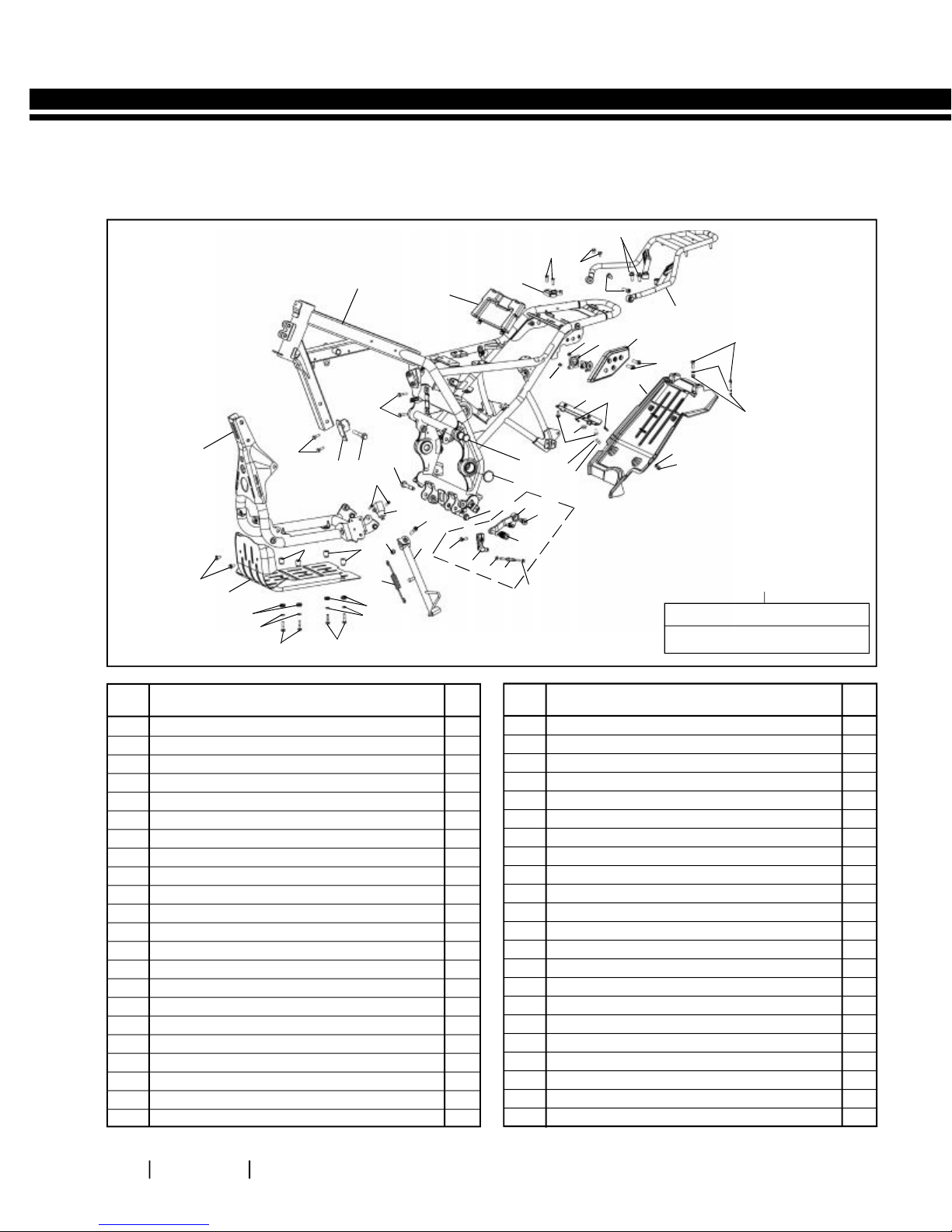
FRAME LH
7
4
5
28
22
27
3
9
20
21
23
24
25
26
6
8
10
11
6
12
18
14
15
9
19
17
16
14
15
13
14
15
A1
Key Nos.
13, 23, 24, 25, 25, 27, 28, 29
40
16
39
37
1
43
13
41
36
14
38
38
42
22
30
34
36
35
37
14
2
31
32
33
13
29
S. NO.
DESCRIPTION
A1 Gear Shift Lever Kit 1
1 Main Frame- Black 1
2 Utility Box 1
3 Seat Latch 1
4 Counter Sunk Screw M6 X 1 X 20 2
5 Flanged Hex Bolt M6 X 1 X 10 2
6 Hex Socket Head Screw M8 X 1.25 X 25 4
7 Flanged Hex Bolt M8 X 1.25 X 20 2
8 Grab Rail Black 1
9 Mushroom Head Screw M6 X 8 X 1 2
10 Plate Seat Lock 1
11 Saddle Bag Mtg - LH 1
12 Piece Mudguard 1
13 Flanged Hex Bolt M6 X 1 X 20 5
14 Plain Washer 8
15 Hex Nut with nylon insert 4
16 Flanged Hex Bolt, M6 X 1 X 14 6
17 Grommet 1
18 Stud 2
19 Crossbar Assy 1
20 Dust Cap-Frame Top 1
21 Dust Cap-Frame 1
QTY. S. NO.
22 Flanged Hex. Bolt M10 X 1.25 X 66 2
23 Toe Lever Comp 1
24 Pivot Pin- Gear Shifter 1
25 Sleeve, Gear Lever 1
26 Hex Nut 1
27 Link Rod 1
28 Hex Nut (LH Thread) 1
29 Gear Shift Lever Comp-Short 1
30 Hex Socket Head Cap Screw – M5 X 20 2
31 Switch-Side Stand 1
32 Hex Socket Head Screw M8 X 1.25 X 35 1
33 Side Stand Assy 1
34 Hex Nyloc Nut M8 X 9.5 1
35 Spring 1
36 Support Bush Skid Plate 4
37 Damper - Oil Cooler 4
38 Flanged Hex Bolt M6 X1 X 35 4
39 Skid Plate 1
40 Cradle Frame 1
41 Bracket Assy-Oil Cooler 1
42 Flanged Hex Bolt, M10 X 1.25 X 75 1
43 Flanged Hex Bolt M6 X1 X 27 2
DESCRIPTION
QTY.

ROYAL ENFIELD HIMALAYAN BS III VEHICLE SERVICE MANUAL
13
EXPLODED VIEWS
FRAME RH
27
26
17
S. NO.
25
24
21
20
19
6
18
16
DESCRIPTION
10
23
22
7
1 Connector Complete Black 1
2 Flanged Hex. Bolt M10 X 1.25 X 66 1
3 Plain Washer 1
4 Flanged Hex Bolt, M10 X 1.25 X 75 1
5 Flange Hex Bolt M10 X 1.25 X 165 1
6 Flange U Nut M10 X 1.25 6
7 Flange Hex Bolt M10 X 1.25 X 183 3
8 Clutch Clamp 1
9 Flanged Hex nut M10X1.25 1
10 Flanged Hex Bolt M8 X 1.25 X 16 2
11 Flanged Hex. Bolt M8 X 1.25 X 45 1
12 Steady Bracket Black 1
13 Flanged Hex. Nut M8 X 1.25 1
14 Flanged Hex Bolt M8 X 1.25 X 20 2
6
7
QTY. S. NO.
15 Flanged Hex Bolt M6 X 1 X 14 2
16 Brake Pedal Comp - RH 1
17 Pivot Pin-Brake Pedal 1
18 Spring-Pedal Return 1
19 Dust Cap-Frame 1
20 Hex Socket Button head Screw M6 X 1 2
21 Dust Cap-Frame Top 1
22 Hex.Socket Button Head Screw M6 X 1 X 16 1
23 plain washer M6 1
24 Flanged Hex Bolt M6 X 1 X 20 1
25 Bracket Assy. - Air Filter 1
26 Saddle Bag Mtg- RH 1
27 Hex Socket Head Screw M8 X 1.25 X 25 2
14
15
13
12
11
10
6
8
9
6
DESCRIPTION
5
1
2
3
4
6
6
QTY.

ROYAL ENFIELD HIMALAYAN BS III VEHICLE SERVICE MANUAL
14
COMPONENTS DISMANTLING SEQUENCE TO REMOVE ENGINE FROM FRAME
Skid Plate on Frame bottom
Engine oil (Drain when warm. Remove drain plug /
oil strainer cover on crankcase LH & Oil filter on Cover
RH)
Oil Cooler along with inlet & outlet pipes.
Fuel hose & Pulse Air valve connections
Battery connections
Magn eto / Gear posit ion / Side stand swit ch:
couplers dismantle
Starter motor connections
Spark plug suppressor cap
Engine steady bracket
Control Cables (Clutch / Accelerator)
Carburettor
Exhaust pipe & Silencer
Gear shift linkage
Starter motor
Cover LH
Gear position indicator sensor
Rear Chain (Remove from FD sprocket)
FD sprocket nut (loosen )
Cover RH
Oil pump gears / Oil pump
Crank shaft Nut (LEFT HAND THREADED)
Balancer shaft Bolt
Clutch center nut & Clutch assembly
Gear shift shaft assembly (Remove circlip & washer
on shift shaft from LH crankcase side first)
Cam shaft covers / Cylinder head cover
Automatic chain tensioner
Cam shaft gear & cam shaft Assembly
Cylinder Head Sub Assembly
Chain Tensioner Pads
Cylinder Barrel Sub Assembly
Cradl e frame top mountings (with connector)
mounting to frame
Cradle frame bottom mounting LH& RH on frame
Magneto rotor assembly including Starter clutch
Starter idler gears with bush & spindles
Rear top engine mounting on frame (support engine
from bottom suitably)
Four mounting studs of Engine to cradle frame

ROYAL ENFIELD HIMALAYAN BS III VEHICLE SERVICE MANUAL
15
ENGINE DISMANTLING FROM FRAME
S.
Aggregate to Dismantle/
No.
Instructions
4.1 Skid plate
Fastener, Size, Tool Usage, Precautions, Photos
Loosen & remove 6
Flanged Hex screws (2 in
front & 4 in bottom.
Remove the spacers and
washers between the
skid plate and frame.
4.2 Oil Cooler
Remove Inlet & Outlet
Banjo union bolts from
LH & RH Crankcase
respectively & allow oil
to drain.
Flanged Hex Screw: M6
Socket Spanner: 10mm
NOTE:
Ensure the engine oil is
drained from the engine.
Banjo Union Bolts: M14
Socket spanner: 19mm
Ensure the 4 washers
are removed from the oil
pipes / banjo Union
Remove 2 Hex flange
bolts securing oil cooler
to the frame
Remove oil cooler along
with inlet & outlet pipes.
(Ensure the Oil pipe No 2
on RH s id e be tw een
engine & frame is taken
out caref ull y, whil e
dism antl ing the oil
cooler.)
Flanged Hex bolts: M6
Socket spanner: 8mm.

ROYAL ENFIELD HIMALAYAN BS III VEHICLE SERVICE MANUAL
16
S.
Aggregate to Dismantle/
No.
Instructions
4.3 Wind Shield
Assembly
Remove 4 Hex socket
head cap screws holding
the Wind shield
assembly to the top
frame.
Remove the 4 plastic
washers along with the
screws and remove wind
shield.
4.4 Trafficator front LH,
RH & cover cockpit
LH, RH.
Fastener, Size, Tool Usage, Precautions, Photos
Hex Soc Hd. Cap Screw:
M5
Allen Key: 4mm
NOTE:
Hold the rubber mounted
nuts from behind while
loosening screws.
Disconnect Trafficator
wiring couplers below
headlamp.
Remove hex socket
head screw mounting
the trafficators to the
top frames on LH & RH
sides.
Gently pull out Cover
cockpit LH & RH from the
rubber grommets in the
top frame LH & RH.
NOTE:
Couplers are color coded as:
LH side: Green
RH side: Red
Hex socket hd. Screw: M5
Allen key: M4

ROYAL ENFIELD HIMALAYAN BS III VEHICLE SERVICE MANUAL
17
S.
Aggregate to Dismantle/
No.
Instructions
4.5 Headlamp
Assembly
Disconnect head lamp
wiring coupler below
head lamp.
Remove the dust caps
from the mounting
holes in top frame LH &
RH.
Fastener, Size, Tool Usage, Precautions, Photos
Remove 2 hex socket
head screws holding
headlamp assembly to
top frame LH & RH &
remove head lamp assy.
4.6 Top frame LH & RH
Remove 2 Flanged Hex
bolts holding the top
frame LH & RH to
Instrument cluster
bracket.
Remove the 2 dust caps
from the connector in
the frame.
Loosen 2 hex socket
head screw clamping
top frames LH & RH, to
connector tube.
Gently rotate & pull out
top frames LH & RH from
connector tube.
Hex Socket Hd. screw:
M5
Allen Key: 6mm
Flanged hex bolts: M8
Socket Spanner: 12mm
Hex Socket Hd. screws:
M6
Socket Spanner: 10mm
CAUTION
Take care not to damage
fuel tank while rotating &
removing the side support
brackets.

ROYAL ENFIELD HIMALAYAN BS III VEHICLE SERVICE MANUAL
18
S.
Aggregate to Dismantle/
No.
4. 7
Instructions
Pillion & Rider Seat
Unlock pillion seat by
turning key clockwise &
lift pillion seat from front
end to release rear tab &
remove.
Lift rider seat from rear
end to release front tab
& remove.
4.8 Fuel tank Dismantling
Fastener, Size, Tool Usage, Precautions, Photos
Remove Seat Assembly
Disconnect fuel hose
from carburetor end.
Remove 2 Hex screws
from the rear end of fuel
tank.
Disconnect fuel gauge
coupler wire by lifting the
tank slightly.
Slide fuel tank towards
rear to release front
clamp from frame
Remove tank along with
the overflow tube
carefully.
CAUTION:
Drain the fuel completely
from the fuel tank.
Hex Flange Bolt M6
Socket Spanner 10 mm
CAUTION :
Do not lift tank too high to
- Preve nt accidental
damage to the front
end of the fuel tank.
- Preve nt damage to
EVAP hose

ROYAL ENFIELD HIMALAYAN BS III VEHICLE SERVICE MANUAL
19
S.
Aggregate to Dismantle/
No.
Instructions
4.9 Steady Engine
Bracket
Hold U nut at the
cylinder head mounting
area with a double end
spanner and loosen Hex
bolt at the front of the
steady engine bracket.
Fastener, Size, Tool Usage, Precautions, Photos
Flanged hex bolt: M10
Socket Spanner: 12mm
Flanged hex nut: M10
Remove the bolt and
nut.
Support steady engine
bracket, Loosen &
remove the 2 Flanged
hex bolts at the rear end
of the bracket and
remove the bolts and
steady engine bracket.
4.10
Throttle cable
Push rubber grommets
down and loosen hex
nuts completely.
Gently pull throttle cable
from bracket to release
the threaded position
from the bracket.
Socket Spanner: 12mm
Double End Spanner:
13mm
Remove inner cable
from the Carburetor.

ROYAL ENFIELD HIMALAYAN BS III VEHICLE SERVICE MANUAL
20
S.
Aggregate to Dismantle/
No.
4.11
Instructions
Clutch Cable
Fastener, Size, Tool Usage, Precautions, Photos
Loosen & remove outer
locknut from the rear of
the cable adjuster.
Loosen inner locknut
fully & push adjuster
fully into bracket.
Release inner cable from
the clevis in the clutch
shaft
Remove rubber grommet
& outer lock nut &
remove clutch cable
from the bracket.
Hex Nut: M8
D E Spanner: 12mm
NOTE:
Gently push the rubber
grommet away from the
adjuster while removing
nut.

ROYAL ENFIELD HIMALAYAN BS III VEHICLE SERVICE MANUAL
21
S.
Aggregate to Dismantle/
No.
4.12
Instructions
Side Panel LH
Fastener, Size, Tool Usage, Precautions, Photos
Remove 3 He x socket
Button head screws
(except left bottom
one).
Gently pull out to release
locater from frame
rubber Grommet.
4.13
Side Panel RH
Remove 3 He x socket
Button head screws
(except right bottom
one).
Hex. Socket Button Hd
Screw M6X12
Allen Key: M5
Hex. Socket Button Hd
Screw M6X12
Allen Key: M5
Gently pull out to release
locater from frame
rubber Grommet.

ROYAL ENFIELD HIMALAYAN BS III VEHICLE SERVICE MANUAL
22
S.
Aggregate to Dismantle/
No.
4.14
Instructions
Electrical connections
Fastener, Size, Tool Usage, Precautions, Photos
A. Battery
Remove negative terminal
scre w and disconnect
negative battery cable.
Remove positive terminal
screw and disconnect
positive battery cable.
B. Starter Motor
Remove the Hex nut
securing the wire eyelet
to starter motor terminal
and remove the wire.
Remove flanged hex
bolt securing the earth
wire eyelet to crankcase.
Philips Hd screw driver
Socket Spanner: 10mm
CAUTION
Ensure Ignition switch &
engine stop switch are in
OFF position before
disconnection battery &
wiring couplers.

ROYAL ENFIELD HIMALAYAN BS III VEHICLE SERVICE MANUAL
23
S.
Aggregate to Dismantle/
No.
4.14
Instructions
Electrical
connections
H. Magneto coupler
Disconnect white
coupler from LH side.
Disconnect small Black
coupler (Pulsar wire
connections from LH
Side.
Fastener, Size, Tool Usage, Precautions, Photos
I. Gear p osi tion s witch
coupler
Disconnect BIG & SMALL
Black coupler from LH
side.
J. Si de st an d sw it ch
coupler
Disconnect Red coupler
from LH side.

ROYAL ENFIELD HIMALAYAN BS III VEHICLE SERVICE MANUAL
24
S.
Aggregate to Dismantle/
No.
4.14
Instructions
Electrical
connections
K. Horn Terminals
Disconnect horn
terminals.
L. Spark plug suppressor
cap
Disconnect suppressor
cap from sparkplug.
Fastener, Size, Tool Usage, Precautions, Photos
4.15
Exhaust pipe &
Silencer
Remove 2 flanged Hex
nuts along with washers
at the cylinder head end.
Release the clamp from
the studs.
Remove 2 Hex bolts &
nuts at the silencer
mounting bracket end.
Support the silencer and
remove the bolt.
Gently pull out the
exhaust pipe from the
cylinder head and
remove exhaust pipe
with silen cer from the
vehicle.
Hex Nuts: M8X1.25
Tubular spanner - 12mm
NOTE
Remove copper washer in
cylinder head, exhaust
pipe seating area after
removing exhaust pipe.
Hex bolts: M8 X 1.25X45
Hex Nuts: M8 X1.25
Socket spanner -12mm
Double End Spanner: 12mm

ROYAL ENFIELD HIMALAYAN BS III VEHICLE SERVICE MANUAL
25
S.
Aggregate to Dismantle/
No.
4.16
Instructions
Gear shifter/
linkage
Fastener, Size, Tool Usage, Precautions, Photos
Loosen Hex bolt on small
gear lever mounted on
gear shaft on LH side of
engine.
Slide out small lever from
shaft.
4.17
Rear Chain Link
Lock
Loosen rear wheel axle
nut sufficiently.
Loosen the chain adjuster
nuts on LH & RH sides of
the swing arm and push
the rear wheel inside, to
create sufficient slack in
the rear chain
Hex flange bolt: M6
Socket spanner: 10mm
Remove chain link lock
and remove chain from
the engine sprocket.

ROYAL ENFIELD HIMALAYAN BS III VEHICLE SERVICE MANUAL
26
S.
Aggregate to Dismantle/
No.
4.18
Instructions
Cradle frame with
Engine, separation
from Main frame
Support cradle frame /
engine suita bly at the
bottom such that it will not
drop of when mounting
bolts are removed.
Fastener, Size, Tool Usage, Precautions, Photos
Loosen Flanged Hex.,
holding cradle frame
top, to main frame.
Remove bolt & connector
complete. (Ensure the
top frame LH&RH and
horn connections are
removed from the
connector tube.)
Loosen Flanged Hex
bolt from the rear top
location of the engine.
DO NOT REMOVE THE
BOLT FROM THE FRAME.
Loosen & remove 2
flanged Hex bolts from
the cradle frame rear
bottom on both LH & RH
sides.
Remove the Flanged Hex
bolt (loosened earlier)
from the rear top
location of the engine.
Hex flange bolt: M10X66
Socket Spanner: 14mm
Hex flange bolt: M10X183
Socket Spanner: 14mm
Hex flange bolts: M10X65
Socket Spanner: 14mm
Loosen & remove
Flanged Hex bolt along
with oil cooler bracket,
holding oil cooler bracket
& cradle frame to main
frame.
Gently remove the support
from the bottom of the
cradle frame / engine
and simul taneously
remo ve cradle frame
with crankcase from
main frame.
Hex flange bolts: M10X75
Socket Spanner: 14mm

ROYAL ENFIELD HIMALAYAN BS III VEHICLE SERVICE MANUAL
27
S.
Aggregate to Dismantle/
No.
4.19
Instructions
Engine separation
from cradle frame
Fastener, Size, Tool Usage, Precautions, Photos
Hold flanged Hex bolt on
Cradle frame top RH side,
and remove Flanged U
nut on the cradle frame
top LH side.
Hold flanged Hex bolt on
Cradle frame bottom RH
side, and remove
Flan ged U nut on the
cradle frame bottom LH
side,
Hold flanged Hex bolt on
Cradle frame rear RH
side, and remove
Flan ged U nut on the
cradle frame rear LH
side.
Remove the 3 studs from
the cradle frame & gently
lift up the engine away
from the frame.
Hex flange bolt: M10X165
Hex U Nut: M10X1.25
Socket Spanner: 14mm
Ring Spanner: 14mm
Hex flange bolts: M10X183
Hex U Nuts: M10X1.25
Socket Spanner: 14mm
Ring Spanner: 14mm

ROYAL ENFIELD HIMALAYAN BS III VEHICLE SERVICE MANUAL
28
INSPECTION & PRECAUTIONS
Inspect all the studs & bolts for bends, distortion, thread wear , threads stripped off etc
Inspect all nuts for thread wear , threads stripped off etc
DO NOT REUSE Nylock Nuts and Hex U nuts, and Pre coated fasteners once they have been tightened and
removed. Replace them every time they have been removed.
DO NOT REUSE Washers, O Rings, Oil seals, Dust seals, rubber and plastic material rubber parts, plastic parts,
gaskets etc once they have been used and removed
Inspect all control cables for internal cables fraying / damage
Carefully inspect studs and nuts that are welded in the frame for any thread damage. If found damaged, use
suitable thread cleaning dies to repair the damages. If the threads are beyond repair, remove the damaged studs/
nuts and reweld new studs / nuts correctly.
Clean the threads in the frame carefully using suitable cleaning and solving agents to clean off dirt and scales
Apply suitable thread locking liquid as appropriate on non precoated fasteners before assembling and tightening
to torque.
Always tighten fasteners diagonally and evenly to the correct specified torque values
Clean, and repaint rusted areas in frame and other parts before assembly

ROYAL ENFIELD HIMALAYAN BS III VEHICLE SERVICE MANUAL
29
TORQUE VALUES
S.
No.
Engine Mtg to Cradle Frame - Flanged Hex Bolt
1
front top M10X1.25X165
Engine Mtg to Cradle Frame - Flanged Hex Bolt
2
front Bottom M10 X1.25X183
Engine Mtg to Cradle Frame - Flanged Hex Bolt
3
Rear Bottom M10X1.25X183
4 Cradle frame Mtg to Frame top Flanged Hex Bolt M10X1.25X60 5 0 5. 0 42.5 4.3 57.5 5.8
Cradle frame Mtg to Frame Hex Flange Bolt
5
rear bottom M10X1.25X65
6 Oil Cooler Mtg to frame Hex Flange M6X1X20 10 1.0 8.5 0.9 11.5 1.2
Steady Bracket Mtg to Hex Flange Bolt
7
Cylinder head M10X1.25X47
8 Steady Bracket Mtg to Frame Hex Flange Bolt M8X1.25X20 25 2.5 21.3 2.1 28. 8 2.9
9 Skid Plate Mtg to Cradle frame Hex Flanged Bolt M6X1X10 10 1.0 8.5 0.9 11.5 1.2
10 Side Panels mounting to frame Hex Button Head M6X1X12 5 0.5 4.3 0.4 5. 8 0.6
11 Gear Shift Linkage Mtg to Frame M10X1.25 30 3.0 25.5 2.6 34.5 3.5
Aggregate Fastener
Torque
NM Kg.M
50 5.0 42.5 4.3 57.5 5 .8
50 5.0 42.5 4.3 57.5 5 .8
50 5.0 42.5 4.3 57.5 5.8
50 5.0 42.5 4.3 57.5 5 .8
50 5.0 42.5 4.3 57.5 5 .8
Min. Torque
(Nm) (Kg.M)
Max. Torque
(Nm) (Kg.M)
12 Gear Shift Linkage to Shift shaft M6X1 10 1.0 8.5 0.9 11.5 1.2
13 Fuel tank Mtg to frame Hex Flange M6X1X27 5 0.5 4.3 0.4 5.8 0.6
14 Exhaust Pipe Mtg to Cyl Head Flanged Hex Nut M8X1.25 1 0 1. 0 8.5 0.9 11.5 1.2
15 Silencer Mtg to Frame Hex Socket M8X1.25X25 25 2.5 21.3 2.1 28. 8 2.9
17 Rear Wheel Spindle Nut Hex U Nut M16X1.5 7 0 7.0 59. 5 6.0 80.5 8.1
18 Chain Adjuster Lock nut Hex Nut M8X1.25 25 2.5 21. 3 2.1 28. 8 2.9
Head Lamp Mtg to Support Hex Soc. Hd. screw
19
Brackets M8X1.25X25
Trafficators Mtg to Support
20
Brackets
Windshield Mtg to Support
21
Brackets
Button Head M6X1X20 5 0 .5 4.3 0.4 5.8 0.6
Hex Socket Head Screws M5X16 5 0.5 4.3 0.4 5.8 0.6
10 1.0 8.5 0.9 11.5 1.2

ROYAL ENFIELD HIMALAYAN BS III VEHICLE SERVICE MANUAL
30
ENGINE ASSEMBLY TO FRAME
S.
Aggregate to Assemble/
No.
4.20
Instructions
Engine on Cradle
Frame
Locate Engine on cradle
frame & ensure the 3
mounting holes of the
cradle frame and th e
engine are aligned.
Insert Hex bolt M10X165
from RH side and
assemble U nut
M10X1.25. DO N OT
TIGHTEN FULLY.
Insert2 flanged Hex bolts
M10X183 from the front
& rear bottom RH side
and assemble U nut
M10X1.25. DO N OT
TIGHTEN FULLY.
Tighte n al l the
mo untings diagonally
to torque.
Hex flange bolts:
M10X165 & M10X183
Hex U Nuts: M10X1.25
Ring Spanner: 14mm.
Socket Spanner: 14mm.
Torque: 50 Nm (5.0 Kg.M)
Fastener, Size, Tool Usage, Precautions, Photos
4.21
Cradle frame with
engine, on Main
Frame
Locate cradle frame /
engine from underneath
main frame and lift up
with suitable support
under engine such that
the stud mounting holes
align as follows:
- Crankcase rear top hole
with frame mounting.
- 2 mounting holes of
cradle frame with 2 holes
in frame down tube.
- 2 mounting holes at the
rear bottom of cradle frame
with 2 holes in main frame.
Insert flanged Hex Bolt
M10X 183 at rear top of
engine and assemble U
nut.
DO NO T TIG HTE N
FULLY.
Hex flange bolts:
M10X183 & M10X165
Hex U Nuts: M10X1.25
Ring Spanner: 14mm.
Socket Spanner: 14mm.
Torque: 50 Nm (5.0 Kg.M)

ROYAL ENFIELD HIMALAYAN BS III VEHICLE SERVICE MANUAL
31
S.
Aggregate to Assemble/
No.
4.21
Instructions
Cradle frame with
engine, on Main
Frame
Locate 2 flanged Hex
bolts M10X65, at rear
bottom, LH & RH sides
and assemble U nuts DO
NOT TIGHTEN FULLY.
Position Oil cooler
mounting bracket in
frame with its small tab
resting on the frame
inside.
Align the mounting hole
with the low er
mounting hole in frame.
Locate Flanged Hex bolt
M10X75, over oil cooler
bracket and assemble U
nut. DO NOT TIGHTEN
FULLY.
Ti ghten all the
mo untings diagonally
to torque.
Fastener, Size, Tool Usage, Precautions, Photos
Hex flange bolt: M10X75
Hex U Nut: M10X1.25
Ring Spanner: 14mm.
Socket Spanner: 14mm.
Torque: 50 Nm (5.0 Kg.M)
4.22
Rear chain
assembly and chain
adjustment
Place vehicle on center
stand with the rear
wheel off the ground.
Ensure rear axle nut, lock
nuts & adjuster nuts on the
LH & RH chain adjusters
are loosened fully.
Push wheel fully inside.
Route rear chain through
final drive sprocket and
locate it on rear wheel
sprocket
Ensure ‘O’ rings are
located on the chain link
and Insert link from the
inside of the chain.

ROYAL ENFIELD HIMALAYAN BS III VEHICLE SERVICE MANUAL
32
S.
Aggregate to Assemble/
No.
4.22
Instructions
Rear chain
assembly and chain
adjustment
Assemble ‘O’ Rings on
the chain link and
assemble the link plate.
Assemble chain link lock
on the chain link,
ensuring the closed end
of the lock is towards the
normal direction of
rotation of the chain.
Fastener, Size, Tool Usage, Precautions, Photos
Tighten adjuster nuts on
LH & RH side evenly till
the chain has a slack of
20 to 25 mm on its top
run.
Ensure the reference
lines on the LH & RH chain
adjusters are matching
at the same reference
lines in the swing arm on
LH & RH sides.
Tighten rear wheel axle
nut to torque.
Tighten lock nuts against
the adjuster nuts on LH
& RH sides.
4.23
Gear Shifter /
Linkage
Locate small lever on
gear shift shaft, ensuring,
small lever is vertical to
ground and the gear
shift pedal is parallel to
rider footrest LH.
Hex U Nut: M17
Socket Spanner: 24mm.
Torque: 70-80Nm
(7.0-8.0Kg.M)
Hex Flange Bolt : M6X20
Socket Spanner : 10mm.
Torque: 10Nm(1.0Kg.M)
Assemble Hex bolt on
gear shift lever short
from the front side and
tighten to torque.

ROYAL ENFIELD HIMALAYAN BS III VEHICLE SERVICE MANUAL
33
S.
Aggregate to Assemble/
No.
4.24
Instructions
Pulse air valve
Connections
Fastener, Size, Tool Usage, Precautions, Photos
Braided hose (PAV to
Cylinder head)
Locate gasket on cylinder
head with a little grease
to hold it in position.
Locate PAV pipe flange
on the gasket. ENSURE
THE OPEN END OF THE
PIPE IS FACING
UPWARDS.
Tighten PAV pipe to
cylinder head with 2 hex
socket head cap screws.
Locate braided hose with
worm clip on the PAV outlet
pipe and tighten screw.
4.25
Exhaust pipe &
Silencer
Locate a new exhaust
pipe gasket on the
exhaust pipe.
Locate exhaust pipe
into the cylinder head,
position the clamp over
the studs on the cylinder
head & assemble 2 hex
nuts M8 DO NO T
TIGHTEN FULLY.
Position silencer
mounting bracket
against the frame at the
rear and insert flanged
hex bolt. Assemble hex
nut over bolt.
Tighten the 2 hex nuts
at the cyli nder head,
first an d t he n t he
silencer bracket nut.
Hd. Cap screws: M6X20
Allen Key: M5
Torque :
NOTE
Asse mble new exhaust
pipe gasket before locating
exhaust pipe in cylinde r
head.
Hex Nuts: M8X1.25
Socket spanner -12mm
Torque: 10Nm (1.0Kg.M.)
Hex bolts: M8 X 1.25X45
Hex Nuts: M8 X1.25
Socket spanner -12mm
Double End Spanner:
12mm
Torque: 25Nm (2.5Kg.M)

ROYAL ENFIELD HIMALAYAN BS III VEHICLE SERVICE MANUAL
34
S.
Aggregate to Assemble/
No.
4.26
Instructions
Throttle Cable
Ensure hex nut and
rubber grommet are
located on the inner
cable properly.
Locate inner cable in the
Carburetor.
Gently pull outer cable
upwards till the inner
cable can be located into
the brake t slot and
release slowly till the
threaded portion of the
outer cable isfully resting
on the bracket.
Tighten outer cable to
bracket using the hex
nut M6.
Slide the rubber
grommets over the
threaded sleeve on
outer cable.
Fastener, Size, Tool Usage, Precautions, Photos
Hex nut : M6
Double end spanner :
10mm
Adjust the throttle cable
free play correctly.

ROYAL ENFIELD HIMALAYAN BS III VEHICLE SERVICE MANUAL
35
S.
Aggregate to Assemble/
No.
4.27
Instructions
Steady engine plate
Position steady engine
plate such that the single
mounting hole aligns
with the cylinder head
mounting location & the
2 mounting holes align
with the welded nuts in
the frame.
Fastener, Size, Tool Usage, Precautions, Photos
Locate 2 Flanged Hex
Bolts over the steady
engine plate.
DO NO T TIG HTE N
FULLY.
Locate Flanged Hex Bolt
at the front end of the
steady bracket, through
the cylinder head &
assemble flange U Nut.
Tighten all the bolts to
torque.
4.28
Electrical
connections
A. St arte r Motor
Connections:
Position earth wire
eyelet on outer
mounting hole of starter
motor & tighten with
flanged hex bolt.
Locate Relay starter
cable on the starter
motor terminal & tighten
with Hex nut.
Flanged hex bolts:
M10X20
Socket Spanner: 12mm
Torque: 20Nm. (2.0Kg.M)
Flanged hex bolt: M10X47
Socket Spanner: 12mm
Flanged hex nut: M10X1.25
Ring Spanner: 12mm
Torque: 50Nm(5Kg.M.)
Socket Spanner: 10mm
Hex flange bolt: M6 X 30
Socketspanner: 8mm
Torque: 8-12Nm
(.8-1.2Kg.M)

ROYAL ENFIELD HIMALAYAN BS III VEHICLE SERVICE MANUAL
36
S.
Aggregate to Assemble/
No.
4.29
Instructions
Electrical
connections
Fastener, Size, Tool Usage, Precautions, Photos
G. Magneto
Connect white coupler
on LH side to wiring
harness
Connect small Black
coupler (Pulsar wire
connections on LH Side
to wiring harness.
H. Gear position switch
CAUTION
Ensure Ignition switch &
engine stop switch is in OFF
position before connecting
any wiring couplers.
NOTE
Connect BIG & SMALL
Black coupler to wiring
harness on LH side.
Ensure Protection
couplers are correctly slid
over the coupler after
connecting. Ensure wiring
harness is correctly
strapped to frame after
connecting couplers.

ROYAL ENFIELD HIMALAYAN BS III VEHICLE SERVICE MANUAL
37
S.
Aggregate to Assemble/
No.
4.29
Instructions
Electrical
connections
I. Si de st and switc h
coupler
Connect Red coupler to
wiring harness on LH
side.
J. Battery Connections
Connect Positive
terminal (Red) to the
positive terminal of the
battery.
Fastener, Size, Tool Usage, Precautions, Photos
Connect negative
terminal (Black) to
negative terminal of the
battery.

ROYAL ENFIELD HIMALAYAN BS III VEHICLE SERVICE MANUAL
38
S.
Aggregate to Assemble/
No.
4.30
Instructions
Fuel tank Assembly
Position fuel tank such
that the front mounting
clamps are correctly
located on the rubber
supports on the frame.
Gently push fuel tank
forward to lock in place.
Lift rear end of the tank
slightly and :
- Route the drain hose
between the frame
without any kinks.
- Connect blue coupler of
Low fuel sensor to wiring
harness
Ensure rubber grommets
are in place in the rear
mounting hole s and
align mounting holes to
the frame,
Locate 2 washers on the
hex flange bolts,
assemble the bolts and
tighten to torque.
Connect fuel hose to fuel
tap and carburetor and
lock the clips in place.
Fastener, Size, Tool Usage, Precautions, Photos
Hex Flange Bolt M6
Socket Spanner 10 mm
Torque 5 NM (0.5 Kg.M)
4.31
Side Panel LH & RH
Locate the tab of the
side panel in the rubber
grommet in frame and
press in gently.
Assemble 3 Hex socket
Button head screws over
the panel and tighten.
Hex. Soc Button Hd Screw:
M6X12
Allen Key: M5
Torque: 5Nm(0.5Kg.M)

ROYAL ENFIELD HIMALAYAN BS III VEHICLE SERVICE MANUAL
39
S.
Aggregate to Assemble/
No.
4.32
Instructions
Side Panel RH
Fastener, Size, Tool Usage, Precautions, Photos
Locate the tab of the
side panel in the rubber
grommet in frame and
press in gently.
Assemble 3 Hex socket
Button head screws over
the panel and tighten.
4.33
Rider & Pillion Seat
Locate the rider seat tab
under the fuel tank and
position the locking plate
centrally on the frame.
Locate rear seat tab in
the frame, align lock pin
with the seat latch and
gently press on seat to
lock.
Hex. Soc Button Hd Screw
M6X12
Allen Key: M5
Torque: 5Nm (0.5Kg.M)
Remove key after
locking pillion seat.
4.34
Connector tube &
Top frames
Position connector tube
from inside the frame
such that the horn
mounting bracket is on
the RH side.
Align mounting holes
with the upper
mounting hole in Frame.
Hex flange bolt: M10X75
Socket Spanner: 14mm.
Torque: 50 Nm (5.0 Kg.M)

ROYAL ENFIELD HIMALAYAN BS III VEHICLE SERVICE MANUAL
40
S.
Aggregate to Assemble/
No.
4.34
Instructions
Connector tube &
Top frames
Locate Flanged Hex bolt
from LH side & thread
into the welded nut
Ensure the 2 Hex socket
screws in top frames LH
& RH are loose & locate
on the connector tube
till they are flush with
the outer surface of the
connector tube.
Do not ti ghte n the
screws.
Fastener, Size, Tool Usage, Precautions, Photos
Hex Socket Hd. Cap
screws: M6
Allen Key: M5
Flanged hex bolts: M8
Socket Spanner: 12mm
Torque: 25Nm(2.5 Kg.M)
Align the mounting
holes of top frames LH &
RH with the holes in the
cockpit mounting
bracket assembly and
tighten using Hex bolts.
Tighten the 2 hex socket
head cap screws on the
top frame LH & RH to
clamp them against the
connector tube.
Ensure the dust caps are
fitted on the connector.
4.35
Horn
Locate horn in the
bracket and tighten.
Connect horn terminals
Flanged Hex Bolts: M8
Socket Spanner: 12mm
Torque: 25Nm(2.5Kg.M)
NOTE
Take care not to damage
fuel tank or fork legs while
assembling the top frames.

ROYAL ENFIELD HIMALAYAN BS III VEHICLE SERVICE MANUAL
41
S.
Aggregate to Assemble/
No.
4.36
Instructions
Trafficator front LH
Fastener, Size, Tool Usage, Precautions, Photos
Locate the front lug of
the cockpit cover into
the rubber grommet in
top frame LH.
Insert trafficator with
GREEN wire coupler into
cover cockpit on LH side.
Tighten trafficator to the
top frame with hex
socket button head
screw & hex nut.
Connect the wiring
coupler to the wiring
harness
4.37
Trafficator front RH
Hex Socket Hd. Cap
screws: M6X20
Allen Key: M5
Hex Nut: M6
Double end spanner:10mm
Torque: 10Nm.(1.0Kg.M.)
NOTE:
Couplers are color coded as:
LH side: Green
RH side: Red
Locate the front lug of
the cockpit cover into
the rubber grommet in
top frame RH.
Insert trafficator with
RED wire coupler into
cover cockpit on RH side.
Tighten trafficator to the
top frame with hex
socket button head
screw & hex nut.
Connect the wiring
coupler to the wiring
harness
Hex Socket Hd. Cap
screws: M6X20
Allen Key: M5
Hex Nut: M6
Double end spanner:10mm
Torque: 10Nm.(1.0Kg.M.)
NOTE:
Couplers are color coded as:
LH side: Green
RH side: Red

ROYAL ENFIELD HIMALAYAN BS III VEHICLE SERVICE MANUAL
42
S.
Aggregate to Assemble/
No.
4.38
Instructions
Headlamp
Assembly
Fastener, Size, Tool Usage, Precautions, Photos
Position head lamp
assembly between top
frames LH & RH an d
ensure the mounting
holes are aligned.
Locate 2 Hex socket
head screws on either
sides of the top frame
and tighten.
Connect head lamp
wiring coupler.
Ensure the dust caps are
fitted in the slots on LH &
RH sides.
4.39
Windshield
Assembly
Locate 4 rubber nuts in
the top frame LH & RH.
Locate wind shield on
the top frame, ensure
the mounting holes are
aligned on both sides
and tighten using 4 Pan
head screws with plastic
washers..
Hex Socket Hd. Cap
screws: M8X25
Allen Key: M6
Torque: 10Nm.(1.0Kg.M.)
NOTE:
Ensure the head lamp beam
is properly aligned before
final torqueing
Pan Head screws: M8X25
Philips screw driver
Torque: 5Nm.(0.5Kg.M.)

ROYAL ENFIELD HIMALAYAN BS III VEHICLE SERVICE MANUAL
43
S.
Aggregate to Assemble/
No.
4.40
Instructions
Clutch Cable
Assembly
Ensure proper location
of inner cable in clutch
lever & outer cable in LH
bracket at handle bar
end.
Ensure proper routing
of cable along the frame
and in sert into the
bracket in cover RH.
Assemble outer lock nut
& larger end of rubber
grommet on the adjuster.
Lock inner cable in the
clevis on Cover RH, gently
pull cable outwards till
resistance is felt & thread
out inner lock nut so that
it rests against the bracket
Ensure 2–3 mm clutch
lever free play at handle
bar end by suitably
turning inner lock nut on
cable cable.
Tighten outer lock nut
against cable bracket.
Fastener, Size, Tool Usage, Precautions, Photos
NOTE:
Ensure the rubber grommet
is correctly positioned
between adjuster & clutch
lever on RH cover

ROYAL ENFIELD HIMALAYAN BS III VEHICLE SERVICE MANUAL
44
S.
Aggregate to Assemble/
No.
4.41
Instructions
Oil Cooler
Insert Oil cooler pipe No
2 from the left side to the
Right side, between the
engine and the cradle
frame.
Fastener, Size, Tool Usage, Precautions, Photos
Position Oil cooler
mounting holes with the
bracket on LH side &
tighten with 2 flanged
Hex bolts
Position 1 each
aluminum washer on
either sides of the hose
banjo union of H os e
no.2 and tighten to
cover RH with Banjo
union bolt.
Position 1 each
aluminum washer on
either sides of the hose
banjo union ofHose no.1
and tighten to
crankcase LH with Banjo
union bolt.
Flanged Hex bolts: M6X20
Socket spanner: 8mm.
Torque: 10Nm.(1.0Kg.M.)
Banjo Union Bolts: M14
Socket spanner: 19mm.
Torque: 38Nm.(3.8Kg.M.)

ROYAL ENFIELD HIMALAYAN BS III VEHICLE SERVICE MANUAL
45
S.
Aggregate to Assemble/
No.
4.42
Instructions
Skid Plate
Assemble the 4 rubber
bushes in the bottom
mounting holes of the
Skid plate and locate 4
damper bushes on the
rubber bushes.
Position the Skid plate
under the cradle frame
and align the mounting
holes. Ensure the
damper bushes do not
fall off.
Assemble 4 Fl an ged
Hex Bolts M6 X1 X 35 at
the bottom of the Skid
plate.
Fastener, Size, Tool Usage, Precautions, Photos
Flanged Hex Screw: M6
Socket Spanner: 10mm
Torque: 10Nm (0.1 Kg.M)
Assemble 2 Flan ged
Hex Bolts, M6 X 1 X 14
at the front of the skid
plate.
Tig hte n all the 6 bolts
evenly and diagonally.

ROYAL ENFIELD HIMALAYAN BS III VEHICLE SERVICE MANUAL
46
SECTION 05 - RIDER & PILLION SEAT
EXPLODED VIEWS
RIDER & PILLION SEAT
1
2
3
4
5
S. NO.
DESCRIPTION
1 Pillion Seat Assy 1
2 Rider Seat Assy 1
QTY. S. NO.
4 Rubber Support - Rear 4
5 Tool Kit Strap 1
4
3
DESCRIPTION
QTY.
3 Rubber Support - Front 4

ROYAL ENFIELD HIMALAYAN BS III VEHICLE SERVICE MANUAL
47
S.
Aggregate to Dismantle/
No.
Instructions
5.1 Rider & Pillion Seat
Dismantling
Unlock pillion seat by
turning key clockwise &
lift pillion seat from front
end to release rear tab &
remove.
Fastener, Size, Tool Usage, Precautions, Photos
Lift rider seat from rear
end to release front tab
& remove.

ROYAL ENFIELD HIMALAYAN BS III VEHICLE SERVICE MANUAL
48
S.
Aggregate to Assemble/
No.
Instructions
5.2 Rider & Pillion Seat
Assembly
Locate the rider seat tab
under the fuel tank and
position the locking
plate ce ntrally on the
frame.
Locate rear seat tab in
the frame, align lock pin
with the seat latch and
gently press on seat to
lock.
Fastener, Size, Tool Usage, Precautions, Photos
Remove key after
locking pillion seat.

ROYAL ENFIELD HIMALAYAN BS III VEHICLE SERVICE MANUAL
49
SECTION 06 - CONTROL CABLES
EXPLODED VIEWS
CONTROL CABLES
1
3
2
S. NO.
1 Clutch Cable Assy. 1
2 Throttle Cable Assembly 1
3 Seat Latch Cable Assy 1
DESCRIPTION
QTY.

ROYAL ENFIELD HIMALAYAN BS III VEHICLE SERVICE MANUAL
50
S.
Aggregate to Dismantle/
No.
Instructions
6.1 Clutch Cable
Removal from
Cover RH end
Fastener, Size, Tool Usage, Precautions, Photos
Loosen outer lock nut of
the cable adjuster on
Cover RH, completely.
Loosen inner locknut
sufficiently such that the
adjuster can be pushed
in to release inner cable
from clutch lever.
Release the inner cable
from the clevis in the
clutch lever on cover RH
Remove the rubber
grommet from the
clutch cable
Remove the outer lock
nut from the clutch cable
Hex Nut: M8
D E Spanner: 12mm
NOTE:
Gently pus h the rubbe r
grommet away from the
adjuster while removing
nut.
Pull out the clutch cable
from the front end of
the bracket.
Removal from Handle bar
end
Remove the outer cable
from the clutch lever
holder assembly at the
handle bar end.
Remove clutch cable
inne r from the clutch
lever
Remove the clutch cable

ROYAL ENFIELD HIMALAYAN BS III VEHICLE SERVICE MANUAL
51
S.
Aggregate to Dismantle/
No.
Instructions
6.2 Throttle Cable
Removal from
Carburetor end
Loosen bottom hex nut
and unscrew till it is free
from the throttle cable
adjuster.
Loosen top lock nut till it
is resting against the top
of the adjuster.
Lift throttle rotor up till
cable becomes free from
the rotor, gently rotate
the cable and remove
from the rotor eyelet.
Remove the bottom lock
nut from the cable
Remove cable adjuster
and inner cable from the
bracket.
Removal from Handle bar
end
Loosen & remove
throttle cable stop plate
screw at the bottom of
the throttle rotor grip
housing on handle bar
RH
Loosen & remove 2
screws at the bottom of
the throttle rotor grip
housing on handle bar
RH.
Lower the housing and
release the inner cable
from the eyelet on the
throttle rotor
Remove the inner cable
on the throttle rotor
housing bottom
Fastener, Size, Tool Usage, Precautions, Photos

ROYAL ENFIELD HIMALAYAN BS III VEHICLE SERVICE MANUAL
52
INSPECTION
Carefully inspect inner cable top and bottom ends for frayed strands, loose noipples on the cable and/ or uneven
wear of the nipple surfaces
Free movement of the inner cable inside outer cable.
Carefully inspect the outer cables for cuts / damages.
Brittleness of the cables and no flexibility.

ROYAL ENFIELD HIMALAYAN BS III VEHICLE SERVICE MANUAL
53
S.
Aggregate to Assemble/
No.
Instructions
6.3 Clutch Cable
Assembly at Handle
bar end
Locate inner cable nipple
in the slot in clutch lever
Locate outer cable in the
clutch lever bracket.
Route cable suitably
along the frame from the
LH side such that the
other end is towards the
clutch cover.
Assembly at Clutch cover
end:
Insert inner cable into
the clutch bracke t on
Cover RH till the inner
lock nut on threaded
adjuster is resting on the
bracket. (Ensure inner
locknut is fully threaded
into adjuster
Insert the outer lock nut
through the inner cable
and thread it on the
adjuster by 3 or 4 turns.
Insert larger end of the
rubber grommet on the
inner cable and position
it on the adjuster.
Locate the inner cable on
the clutch lever clevis.
Gently pull the cable
adjuster out of the
bracket - as far as possible
and tighten outer lock
nut against the bracket.
Check clutch lever free
play is between 2-3 mm
and tighte n /loosen
inner lock nut.
Tighten outer locknut
against clutch bracket.
Fastener, Size, Tool Usage, Precautions, Photos
NOTE:
Ensure proper seating of
rubber grommet on the
cable adjuster.
Hex Nut: M8
D E Spanner: 12mm

ROYAL ENFIELD HIMALAYAN BS III VEHICLE SERVICE MANUAL
54
S.
Aggregate to Assemble/
No.
Instructions
6.4 Throttle cable
Assembly at Handle
bar end
Route throttle cable
inne r through the
bottom half of the
throttle rotor housing.
Fastener, Size, Tool Usage, Precautions, Photos
Insert throttle rotor on
handle bar RH and locate
inner cable in the rotor
eyelet
Support bottom half of
the throttle rotor
housing against handle
bar and ensure proper
resting of throttle rotor
on top of the housing.
Position top housing
over bottom housing,
ensuring the mounting
holes are matching and
the throttle rotor is
located in the slot in the
housing and rotates freely.
Locate long head screw
in front mounting hole
and the short screw in
rear mounting hole of
bottom housing and
tighten evenly till the
housing are firmly
tightened against
handle bar.
NOTE:
Ensure free rotation of the
throttle rotor in handle
bar.
NOTE:
Ensure free movement of
throttle rotor and cable
before tightening the
screws fully.
Philips head screw driver
Locate throttle cable
stop plate on outer cable
and tighten to bottom
housing with screw.
Route the throttle cable
below fuel tank and strap
properly to frame.

ROYAL ENFIELD HIMALAYAN BS III VEHICLE SERVICE MANUAL
55
S.
Aggregate to Assemble/
No.
Instructions
6.4 Throttle cable
Assembly on
carburetor end
Ensure top lock nut in
the cable adjuster is fully
threaded into adjuster
and insert cable into the
bracket on carburetor
end.
Assemble bottom lock
nut on cable adjuster.
Locate inner cable in the
throttle rotor eyelet .
Gently pull the adjuster
upwards and tighten
top lock nut against the
bracket
Fastener, Size, Tool Usage, Precautions, Photos
Ensure free play of 2 –
3mm at the throttle rotor
at the handle ba r end
and adjust top lock nut
accordingly.
Tighten bottom lock nut
against the bracket at
carburetor end
Hex Nut: M6
D E Spanner: 10mm
ROYAL ENFIELD HIMALAYAN BS III VEHICLE SERVICE MANUAL
56
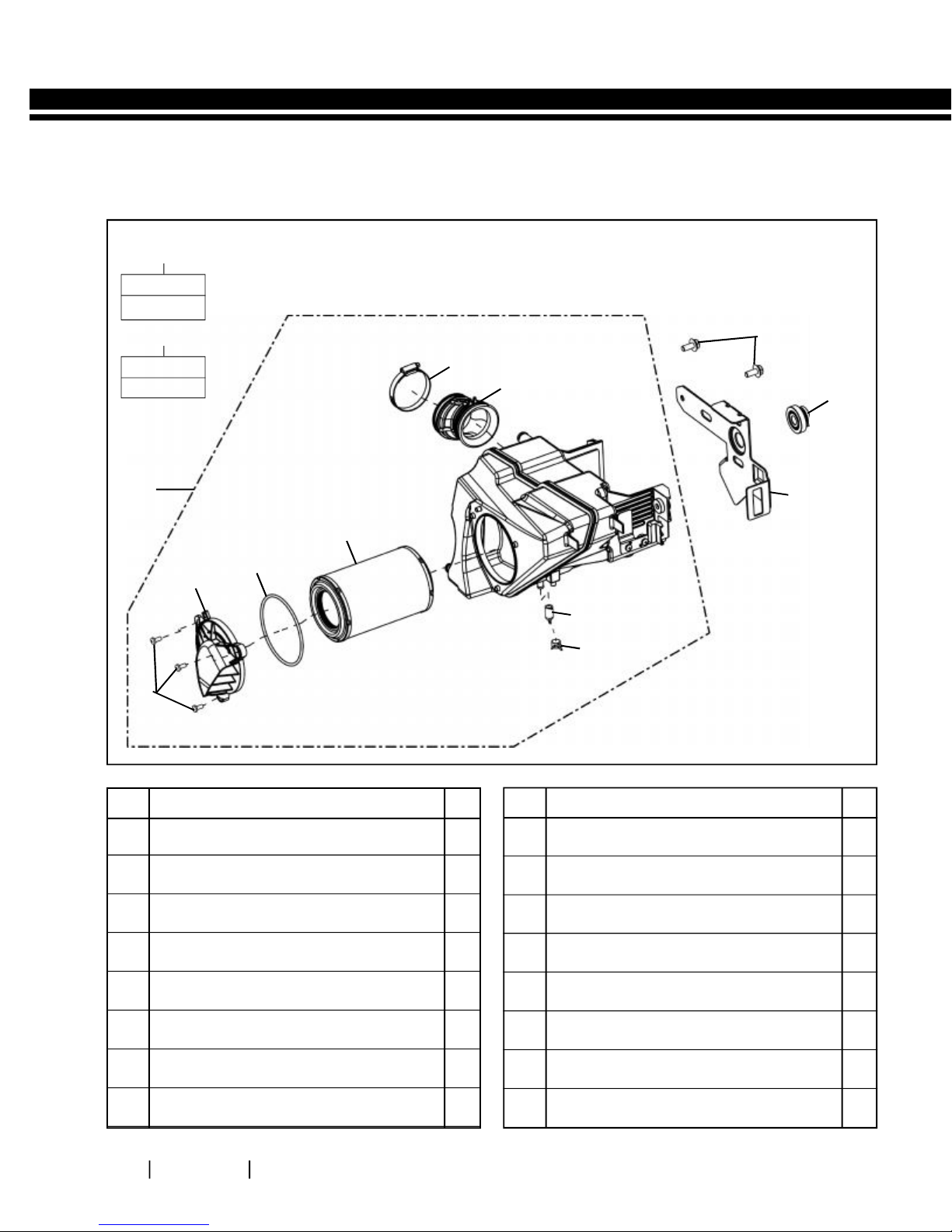
SECTION 07 - AIR FILTER
EXPLODED VIEWS
AIRFILTER
A1
Key Nos.
3 & 4
A2
Key Nos.
1 to 8
5
9
6
10
A2
4
2
1
S. NO.
3
DESCRIPTION
A1 A/F Element Kit 1
A2 Air Filter Box Assembly 1
1 Pan Head Screw M5 X12 3
QTY. S. NO.
7 Drain Tube 1
8 Clip 1
9 Hex Flange Bolt, M6 X 1 X 14 2
11
7
8
DESCRIPTION
QTY.
2 Inlet Cover 1
3 Seal 1
4 Element Air Filter 1
5 Clamp 1
6 Pipe Outlet 1
10 Rear Damper - Tank 1
11 Lid – Battery Carrier 1

ROYAL ENFIELD HIMALAYAN BS III VEHICLE SERVICE MANUAL
57
S.
Aggregate to Dismantle/
No.
Instructions
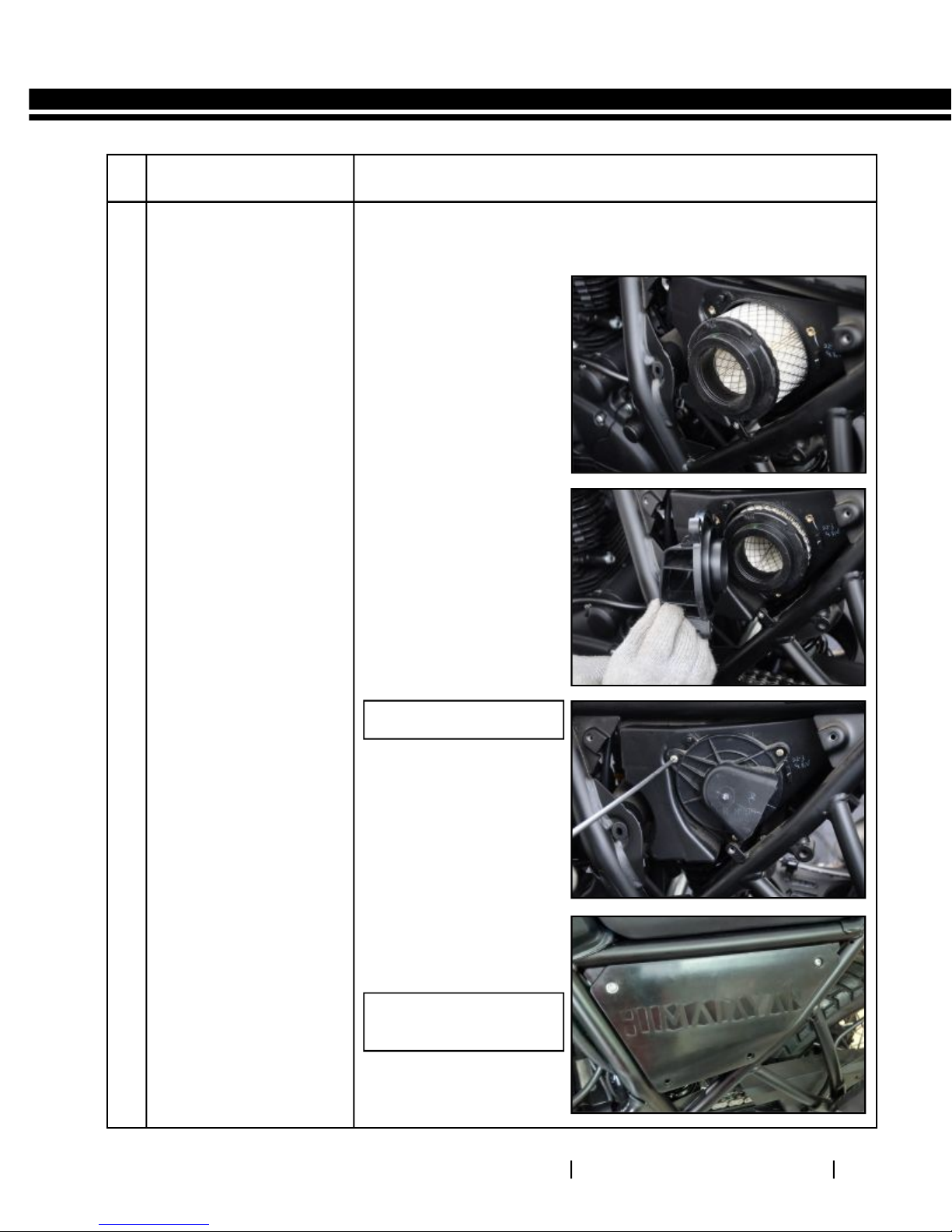
7.1 Air filter Element
from housing
Fastener, Size, Tool Usage, Precautions, Photos
Remove 2 hex socket
button head screws
from the LH side panel.
Pull out the side panel
gently to release from
the grommet in the
frame.
Loosen & Remove the 3
Pan head screws from
the air filter cover.
Remove Cover.
Pan head Screw M5
Allen Key 4mm
Pan head Screw M5
Allen Key 4mm
Remove air filter element
from housing.

ROYAL ENFIELD HIMALAYAN BS III VEHICLE SERVICE MANUAL
58
S.
Aggregate to Dismantle/
No.
Instructions
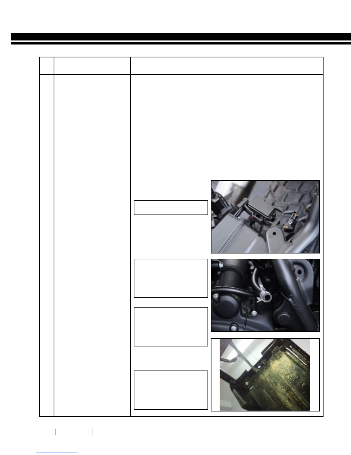
7.2 Air filter Housing
from frame
Fastener, Size, Tool Usage, Precautions, Photos
Disconnect battery
terminals and remove
from air filter housing.
(refer electricals section
for dismantling battery)
Remove 4 flanged hex
bolts and remove piece
mudguard.
Disconnect breather
hose from air filter
housing
Loosen carburetor
worm clip sufficiently.
Loosen & remove 2
flanged hex bolts,
holding air filter housing
to frame
Gently pull out Fuse box
along with its rubber
holder from air filter
housing
Remove RR unit with its
rubber holder from air
filter housing
Loosen and remove 3
flange hex bolts holding
the cross bar assembly
below air filter housing
to frame
Remove cross bar
assembly
Loosen flanged Hex
bolt, holding bracket air
filter to frame and
remove the bolt and
bracket air filter.
Remove air filter housing
from rear side of the
frame.
Hex Bolts: M6
Socket spanner: 8mm
Screw driver
Hex Bolts: M8
Socket spanner: 12mm
NOTE:
Ensure the wiring connections
are removed
Hex Bolts: M6
Socket spanner: 10mm
Hex Bolts: M8
Socket spanner: 12mm

ROYAL ENFIELD HIMALAYAN BS III VEHICLE SERVICE MANUAL
59
INSPECTION & CLEANING
Inspect air filter element carefully for any deformation, damages, heavily clogged with dirt, soggy condition, and
/ or foreign particles embedded in the element. Replace if any of these conditions are observed.
Inspect rubber seals, hoses, for cuts, cracks, damages.
Clean Air filter element every 5,000 Kms OR more frequently if motorcycle is used in dusty / Off road conditions.
Gently Tap filter element with minimum force to dislodge heavy / embedded dust particles.
Use compressed air from the outside of the filter element to remove dust particles
Clean the element on the inside and outside using a soft cloth
Clean the insides of the air filter housing and cover using a soft cloth
Replace seals, ‘O’ Rings and rubber parts whenever the induction system is serviced.
Replace Air filter element every 15,000 Kms or earlier if motorcycle is used in dusty / off road conditions.
TORQUE VALUES
S.
No.
1 Bracket Assy-Airfilter top Flanged Hex Bolt M8 X 1.25 X 16 22.5 2.25
2 Bracket Assy-Airfilter bottom Flanged Hex Bolt M6 X 1 X 20 10 1.0
3 Crossbar Assy Flanged Hex Bolt, M6 X 1 X 14 10 1.0
4 Piece mudguard Flanged Hex Bolt, M6 X 1 X 20 1 0 1. 0
5 Lid battery carrier Flanged Hex Bolt, M6 X 1 X 14 10 1.0
Aggregate Fastener
Torque
NM Kg.M
Min. Torque
(Nm) (Kg.M)
20 2.0
8 0. 8
8 0. 8
8 0. 8
8 0. 8
Max. Torque
(Nm) (Kg.M)
25 2.5
12 1.2
12 1.2
12 1.2
12 1.2
ROYAL ENFIELD HIMALAYAN BS III VEHICLE SERVICE MANUAL
60
S.
Aggregate to Assemble/
No.
Instructions
7.3 Air filter Housing
on frame
Position air filter
housing inside frame
from rear side with its
outlet hole facing
carburetor.
Ensure connecting is
correctly & fully seated
on both air filter and
carburetor & tighten hose
clip to prevent slipping
of the connection tube
Fastener, Size, Tool Usage, Precautions, Photos
Screw driver
Locate cross bar assembly
under air filter housing
and tighten to frame
using 2 flanged hex bolts.
Position bracket assembly,
air filter on frame RH side
and tighten using
flanged hex bolt M8 on
top and 2 M6 flanged
hex bolts at bottom.
Assemble piece mudguard
and tighten to frame
with flanged bolts,
washers and nylock nuts.
Assemble batter y,
connect terminals, locate
lid battery carrier in
housing and tighten with
hex bolts. (Refer electricals
section for battery
assembly)
Flanged Hex Bolts: M6
Socket spanner: 8mm
Torque:8-12Nm(0.8-1.2
KgM.)
Flanged Hex Bolt: M8
Socket spanner: 12mm
Torque:20-25Nm(2.0-2.5
KgM.)
Flanged Hex Bolt: M6
Socket spanner: 8mm
Torque: 8-12Nm(0.8-1.2
KgM.)
ROYAL ENFIELD HIMALAYAN BS III VEHICLE SERVICE MANUAL
61
S.
Aggregate to Assemble/
No.
Instructions
7.4 Air filter Element
into housing
Locate air filter element
in housing such that the
open end of the element
is facing outside.
Locate cover on the air
filter housing such that
the locating pegs and the
three mounting hole s
are aligned.
Fastener, Size, Tool Usage, Precautions, Photos
Tighten cover with 3
screws evenly and firmly
Locate side panel with its
bottom leg located in the
rubber grommet
Tighten side panel with
2 hex socket button
head screws
Philips head screw driver
Pan head screw M5
Allen Key 4mm

ROYAL ENFIELD HIMALAYAN BS III VEHICLE SERVICE MANUAL
62
SECTION 08 - PULSE AIR VALVE
EXPLODED VIEWS
PULSE AIR VALVE
3
2
12
1
13
10
14
4
5
6
7
5
6
8
13
9
S. NO.
DESCRIPTION
1 PAV - Air Filter Hose 1
2 Clip 1
3 Flange Nyloc Type Nut M6 X 1 2
4 Pulse Air Valve 1
5 Damper - Oil Cooler 2
6 Spacer - Oil Cooler 2
7 Hex flange bolt M6 X 30 2
QTY. S. NO.
8 Clip – PAV Adaptor 2
9 PAV Adaptor Hose 1
10 Gasket Mounting Plate 1
11 Braided Hose assy 1
12 SS Hose Clip 1
13 Hex Socket Head Cap Screw M6 X 20 2
14 Clip - PAV air filter hose 1
DESCRIPTION
8
QTY.

ROYAL ENFIELD HIMALAYAN BS III VEHICLE SERVICE MANUAL
63
S.
Aggregate to Dismantle/
No.
Instructions
8.1 Pulse air valve pipe
connections
Remove fuel tank from
frame.
Gently expand the clip
and disconnect rubber
hose from inlet
manifold.
Disconnect air inlet hose
from pulse air valve.
Puls e a ir va lv e b ra id ed
hose:
Fastener, Size, Tool Usage, Precautions, Photos
Loosen screw on the SS
hose clip.
Loosen & remove 2 hex
socket head cap screws
holding braided hose
flange to cylinder head
on the exhaust end.
Gently pull out braided
hose from pulse air valve
bottom tube and
remove along with
gasket.
Pulse air valve from frame:
Holding the nuts on the
inside, loosen and
remove the 2 flanged
hex bolts from frame
Remove pulse air valve
from frame, taking care
not to drop the spacers
and dampers
Screw driver
Hex. Soc head cap screw:
M6X20
Allen Key 5mm
Hex bolts & nuts: M6
Double end spanner:
8mm

ROYAL ENFIELD HIMALAYAN BS III VEHICLE SERVICE MANUAL
64
INSPECTION
Inspect the hoses for ageing, cuts and / or cracks. Replace as recommended.
Inspect braided hose for any leaks, cracks and proper sealing at cylinder head
TORQUE VALUES
S.
No.
1 Braided hose mtg to cyl head Hex Socket Head Cap Screw M6 X 20 10 1.0
2 PAV mtg to frame Hex flange bolt M6 X 30 10 1.0
Aggregate Fastener
Torque
NM Kg.M
Min. Torque
(Nm) (Kg.M)
8 0. 8
8 0. 8
Max. Torque
(Nm) (Kg.M)
12 1.2
12 1.2

ROYAL ENFIELD HIMALAYAN BS III VEHICLE SERVICE MANUAL
65
S.
Aggregate to Assemble/
No.
Instructions
8.2 Pulse air valve on
frame
Locate pulse air valve in
the frame such that the
outlet is facing down, the
inlet from carburetor is
on the RH side and the
inlet from air filter is on
the Left side of the frame
Fastener, Size, Tool Usage, Precautions, Photos
Ensure the dampers and
spacers are in place in
the mounting locations
and tighten with 2 hex
flange bolts M6X30
Apply grease on the
gasket and locate it on
the cylinder head
Locate worm clip on the
braided hose and
assemble braided hose
on the outlet tube of the
pulse air valve
Position braided hose
flange over the gasket on
cylinder head , align the
holes and tighten with
two hex socket head cap
screws
Flanged Hex Bolts: M6
Socket spanner: 8mm
Torque:10-12Nm
(1.0-1.2 Kg.M)
Screw driver
Hex soc hd cap screws:
M6X20
Allen key: M5
Torque:10-12Nm
(1.0-1.2 Kg.M)
Tighten worm clip over
the braided hose.
Connect the rubber
hoses from airfilter and
inlet manifold
respectively and slide
the clips in place.

ROYAL ENFIELD HIMALAYAN BS III VEHICLE SERVICE MANUAL
66
SECTION 09 - FUEL TANK
EXPLODED VIEW
FUEL TANK
15
11
1
2
3
4
12
13
14
S. NO.
DESCRIPTION
1 Fuel Tank With Sticker 1
2 Flanged Hex Bolt M6 X 1 X 27 2
3 Bush - Fuel Tank 2
4 Rear Damper-Tank 2
5 Fuel Hose 1
6 Drain Hose 1
7 Fuel Tap Assy 1
8 Plain Washer 2
11
QTY. S. NO.
9 Fiber Washer 2
10 Hex socket head cap screw M6X16 2
11 Front Damper-Tank 2
12 O Ring-Fuel Gauge 1
13 Fuel Level Sensor Unit 1
14 Hex Flange Nut M5 X 0.8 4
15 Hex socket head cap screw M5X16 3
10
7
8
9
5
6
DESCRIPTION
QTY.

ROYAL ENFIELD HIMALAYAN BS III VEHICLE SERVICE MANUAL
67
S.
Aggregate to Dismantle/
No.
Instructions
9.1 Fuel tank -
Dismantling
Fastener, Size, Tool Usage, Precautions, Photos
Remove Seat Assembly
Disconnect fuel hose
from carburetor end.
Remove 2 Hex screws
from the rear end of fuel
tank.
Disconnect fuel gauge
coupler wire by lifting the
tank slightly.
Slide fuel tank towards
rear to release front
clamp from frame.
Remove tank along with
the overflow tube
carefully.
CAUTION:
Drain the fuel completely
from the fuel tank.
Hex Flange Bolt M6
Socket Spanner 10 mm
CAUTION :
Do not lift tank too high to
- Prevent accidental
damage to the front
end of the fuel tank.
- Prevent damage to
EVAP hose

ROYAL ENFIELD HIMALAYAN BS III VEHICLE SERVICE MANUAL
68
INSPECTION
Carefully inspect fuel hose and vent hose for damage, cuts, cracks, holes, wear or general deterioration. Replace
if necessary.
WARNING
Gasoline is extremely flammable and highly explosive, which could result in serious injury.
Do not smoke or allow open flame or sparks in the vicinity.
Store the fuel carefully to avoid spillage.
TORQUE VALUES
Aggregate FastenerComponent
Torque Range
NM Kg-M
Fuel Tank Fuel tank Mounting Flanged Hex Bolt M6 * 1*27 5 0.5

ROYAL ENFIELD HIMALAYAN BS III VEHICLE SERVICE MANUAL
69
S.
Aggregate to Assemble/
No.
Instructions
9.2 Fuel tank Assembly
Position fuel tank such
that the front mounting
clamps are correctly
located on the rubber
supports on the frame.
Gently push fuel tank
forward to lock in place.
Lift rear end of the tank
slightly and :
- Route the drain hose
between the frame
without any kinks.
- Connect blue coupler of
Low fuel sensor to wiring
harness
Fastener, Size, Tool Usage, Precautions, Photos
Ensure rubber grommets
are in place in the rear
mounting hole s and
align mounting holes to
the frame,
Locate 2 washers on the
hex flange bolts,
assemble the bolts and
tighten to torque.
Connect fuel hose to fuel
tap and carburetor and
lock the clips in place.
Hex Flange Bolt M6
Socket Spanner 10 mm
Torque 5 NM (0.5 Kg.M)

ROYAL ENFIELD HIMALAYAN BS III VEHICLE SERVICE MANUAL
70
SECTION 10 – EXHAUST PIPE & SILENCER
EXPLODED VIEWS
EXHAUST PIPE & SILENCER
1
3
1
2
4
5
6
7
1
5
13
8
12
9
11
10
9
1
5
S. NO.
DESCRIPTION
1 Flanged Hex. Nut M8 X 1.25 4
2 Exhaust Gasket 1
3 Exhaust Pipe Assy 1
4 Guard, Cat Pipe 1
5 Philips Pan Head Screw M6 X 6 6
6 Guard Exhaust Pipe 1
7 Clamp Silencer 1
QTY. S. NO.
8 Hex Flange Bolt M8 X 1.25 X 38 1
9 Pin Damper 2
10 Damper Bush 1
11 Silencer Assy 1
12 Hex Flange Bolt M8 X 1.25 X 55 1
13 Guard Silencer 1
DESCRIPTION
QTY.

ROYAL ENFIELD HIMALAYAN BS III VEHICLE SERVICE MANUAL
71
S.
Aggregate to Dismantle/
No.
Instructions
10.1 Exhaust pipe &
Silencer
Fastener, Size, Tool Usage, Precautions, Photos
Remove 2 flanged Hex
nuts along with washers
at the cylinder head end.
Release the clamp from
the studs.
Remove 2 Hex bolts &
nuts at the silencer
mounting bracket end.
Support the silencer and
remove the bolt.
Gently pull out the
exhaust pipe from the
cylinder head and
remove exhaust pipe
with silen cer from the
vehicle.
Hex Nuts: M8X1.25
Socket spanner -12mm
NOTE:
Remove copper washer in
cylinder head, exhaust
pipe seating a rea after
removing exhaust pipe.
Hex bolts: M8 X 1.25X45
Hex Nuts: M8 X1.25
Socket spanner - 12mm
Double End Spanner: 12mm

ROYAL ENFIELD HIMALAYAN BS III VEHICLE SERVICE MANUAL
72
INSPECTION
Inspect Silencer and Exhaust assembles for any damages / dents as it might cause damage to the internals.
Inspect silencer and exhaust pipe joint for any signs of exhaust gas leakage.
CAUTION :
Do not clean the silencer and exhaust internals with any solvents, gasoline etc as it will damage the catalytic
converters.
REPLACE
Copper gasket between exhaust pipe and cylinder head whenever exhaust pipe is dismantled from cylinder
head.
S No. Aggregate Fastener
1 Exhaust Pipe Mounting to Cyl.head Flanged Hex Bolt M8 X 1.25 X 16 10 1
2 Silencer Mounting to Frame Hex Socket M8X1.25X25 25 2.5
Torque Range
NM Kg-M

ROYAL ENFIELD HIMALAYAN BS III VEHICLE SERVICE MANUAL
73
S.No.-
Aggregate to Assemble/
Instructions
10.2
Exhaust pipe &
Silencer
Locate a new gasket on
the exhaust pipe.
Locate exhaust pipe
into the cylinder head,
position the clamp over
the studs on the cylinder
head & assemble 2 hex
nuts M8 DO NO T
TIGHTEN FULLY.
Position silencer
mounting bracket
against the frame at the
rear and insert flanged
hex bolt. Assemble hex
nut over bolt.
Fastener, Size, Tool Usage, Precautions, Photos
Hex Nuts: M8X1.25
Socket spanner -12mm
Torque: 10Nm (1.0Kg.M.)
Tighten the 2 hex nuts at
the cylinder head, first
and then the silence r
bracket nut.
Hex bolts: M8 X 1.25X45
Hex Nuts: M8 X1.25
Socket spanner -12mm
Double End Spanner: 12mm
Torque: 25Nm (2.5Kg.M)

ROYAL ENFIELD HIMALAYAN BS III VEHICLE SERVICE MANUAL
74
SECTION 11 - TOP BRACKET, HANDLE BAR,
FRONT MUDGUARD, FRONT WHEEL FRONT
SUSPENSION & STEERING STEM

ROYAL ENFIELD HIMALAYAN BS III VEHICLE SERVICE MANUAL
75
EXPLODED VIEWS
TOP FRAME, WINDSCREEN & COCKPIT BRACKET
A1
Key Nos.
11 (4 Nos.),
12 (4 Nos.),
& 13
3
13
12
11
12
11
10
9
8
7
6
4
2
1
5
22
14
15
16
18
14
15
16
14
15
16
19
8
17
6
7
5
20
S. NO.
DESCRIPTION
1 Top frame LH with Decal 1
2 Dust Cap - Connector Comp 2
3 Decal LH 1
4 Cover Cockpit LH 1
5 Flanged Hex Bolt M8 2
6 Dust Cap-Frame Top 2
7 Grommet 2
8 Rubber Nut-M5 4
9 Cover Cockpit Top 1
10 Hex.Socket Button Head Screw M6X1 2
11 Washer Plastic 4
21
22
QTY. S. NO.
2
DESCRIPTION
12 Hex socket head cap screw M5X16 4
13 Wind Shield 1
14 Grommet-Cluster 3
15 Plain Washer 3
16 Hex Nut M6 with nylon insert 3
17 Cockpit Mtg bracket- Black 1
18 Hex Socket Head Cap Screw M8 X 45 2
19 Top frame RH with Decal 1
20 Cover Cockpit RH 1
21 Decal RH 1
22 Hex Socket Head Cap Screw-M6 2
QTY.

ROYAL ENFIELD HIMALAYAN BS III VEHICLE SERVICE MANUAL
76
FRONT MUDGUARD
1
2
3
7
4
5
6
S. NO.
DESCRIPTION
1 Insert- Front Fender 4
2 Front Mudguard with sticker assy - Black 1
3 Flanged Hex Bolt M6 X 1 X 27 4
4 Hex. Socket Head Cap Screw- M6 X 20 4
QTY. S. NO.
5 Fork Brace- Yenmar Bronze 1
6 Front Mudguard - Bottom 1
7 Hex. Socket Button Head Screw M6 X 1 4
DESCRIPTION
QTY.

ROYAL ENFIELD HIMALAYAN BS III VEHICLE SERVICE MANUAL
77
FRONT WHEEL
1
2
17
16
3
13
4
5
6
7
8
15
13
12
14
10
11
9
S. NO.
DESCRIPTION
1 Tyre - Front 1
2 Tube - Front 1
3 Rim Tape- Front 1
4 Rim Front 1
5 Disc- Front 1
6 Hex Flanged Bolt M8 X 1.25 X 25 6
7 Spokes Front 36
8 Nipple 36
9 Hex U Nut M16 X1.5 1
10 Washer 1
QTY. S. NO.
DESCRIPTION
11 Spacer 1
12 Grease Seal, ,25x40x7 1
Deep Groove Sealed Ball Bearing 6203
13
(17 X 40 X 12)
14 Spacer - Front Hub 1
15 Front Hub Assy 1
16 Wheel Speed Sensor Assy 1
17 Spindle - Front Wheel 1
QTY.
2

ROYAL ENFIELD HIMALAYAN BS III VEHICLE SERVICE MANUAL
78
FRONT FORK
28
27
22
26
23
25
24
A2
20
19
18
17
1
16
21
12
11
10
15
14
13
7
8
9
2
3
4
5
6
A1
S. NO.
DESCRIPTION
A1 Front Fork Assy. LH 1
A2 Front Fork Assy. RH 1
1 Inner Tube Assy. 2
2 Dust Seal 2
3 Circlip (Snap - Ring 2
4 Oil Seal 2
5 Bush Washer 2
6 Bush (Outer Tube) 2
7 Outer Tube RH 1
8 Gasket 2
9 Bolt M10X1 2
10 Hex Socket Head Screw M8 X 1.25 X 25 1
11 Spindle Taper 2
12 Piston - Front Fork 2
13 Spring - 2 (Short) 2
QTY. S. NO.
14 Piston Ring 2
15 Spring – 1 (Long) 2
16 Washer Spring Top 2
17 Spacer 2
18 Washer - 2 2
19 ‘O’ Ring 2
20 Bolt Cap 2
21 Outer Tube LH 1
22 Cable Guide - Brake Hose 1
23 Cable Guide - Speedo Cable 1
24 Lock Washer, M6 2
25 Plain Washer 2
26 Hex. Bolt M6 X 12 2
27 Bellow Fork 2
28 Fork Gaiter Clip 2
DESCRIPTION
QTY.

ROYAL ENFIELD HIMALAYAN BS III VEHICLE SERVICE MANUAL
79
HANDLE BAR
1
2
3 4
6
5
16
7
8
10
Key Nos.
1 to 18
Key Nos.
17 (2 Nos)
S. NO.
A1
A2
& 18
15
DESCRIPTION
9
14
17
14
18
QTY. S. NO.
11
DESCRIPTION
12
13
2
1
QTY.
A1 Handle Bar Assy Comp with Switch etc 1
A2 Clamp Kit Front M/C 1
1 Hex Socket Head Screw M8 X 48 2
2 Counter Weight Assy 2
3 Hand Grip LH 1
4 Switch Module LH 1
5 Handle Bar Complete 1
6 Rear View Mirror LH 1
7 Lever & Holder Assy- LH 1
8 Clutch Switch 1
9 Front Brake Switch 1
10 Rear View Mirror RH 1
11 Master Cylinder - Front 1
12 Switch Module RH 1
13 Grip Comp. Throttle RH 1
14 Mountable Strap- Handle bar 2
15 Bracket - Lever, Clutch LH 1
16 Clutch Lever 1
17 Screw - Clutch Switch 2
18 Screw Brake lever fixing 1

ROYAL ENFIELD HIMALAYAN BS III VEHICLE SERVICE MANUAL
80
STEERING STEM
1
4
2
4
3
5
10
8
9
12
16
13
14
15
4
6
7
10
11
S. NO.
DESCRIPTION
1 Hex Socket Head Screw M8 X 45 4
2 Top Raiser-Handle Bar 1
3 Lock Nut 1
4 Hex Socket Head Screw M8 X 1.25 X 25 8
5 Top Yoke 1
6 Hex. Socket Head Cap Screw- M6 X 20 2
7 Ring Nut 1
8 Clip Holder Assy - Wiring Harness 1
9 Flanged Hexagonal Bolt M6 X 1 X 10 2
4
QTY. S. NO.
10 Dust Seal-Steering Assy 2
11 Tapered Roller Bearing - 30205 (25 X 52) 2
12
13 Hex Bolt - M6 X 1 X 12 2
14 Plain Washer 2
15 Bracket Comp Number Plate 1
16 Number Plate – Front 1
17
18 Clamp-Wheel Speed Sensor 1
18
DESCRIPTION
Steering Stem Assy. with Bearings & Dust Seals
Cross Recessed Pan Head Screw M5 X 0.8 X 12
17
QTY.
1
2

ROYAL ENFIELD HIMALAYAN BS III VEHICLE SERVICE MANUAL
81
S.
Aggregate to Dismantle/
No.
Instructions
11.1 Top Frame LH & RH
Wind Shield
Assembly
Fastener, Size, Tool Usage, Precautions, Photos
Remove 4 Hex socket
head cap screws holding
the Wind shield
assembly to the top
frame.
Remove the 4 plastic
washers along with the
screws and remove wind
shield.
11.2 Trafficator front LH,
RH & cover cockpit
LH, RH.
Disconnect Trafficator
wiring couplers below
headlamp.
Remove hex socket
head screw mounting
the trafficators to the
top frames on LH & RH
sides.
Hex Soc Hd. Cap Screw:
M5
Allen Key: 4mm
NOTE:
Hold the rubber mounted
nuts from behind while
loosening screws.
NOTE:
Couplers are color coded
as:
LH side: Green
RH side: Red
Hex Soc Hd. Cap crews:M5
Allen Key: 4mm
Hex Nut: M6
Double end spanner:10mm
Gently pull out Cover
cockpit LH & RH from the
rubber grommets in the
top frame LH & RH.

ROYAL ENFIELD HIMALAYAN BS III VEHICLE SERVICE MANUAL
82
S.
Aggregate to Dismantle/
No.
Instructions
11.3 Headlamp
Assembly
Disconnect head lamp
wiring coupler below
head lamp.
Remove the dust caps
from the mounting holes
in top frame LH & RH.
Remove 2 hex socket
head screws holding
headlamp assembly to
top frame LH & RH &
remove head lamp assy.
Fastener, Size, Tool Usage, Precautions, Photos
Hex soc hd. cap screws:
M8
Allen Key: 6mm
11.4
Top frame LH & RH
Remove 2 Flanged Hex
bolts holding the top
frame LH & RH to
Instrument cluster
bracket.
Remove the 2 dust caps
from the connector in
the frame.
Loosen 2 hex socket
head screw clamping
top frames LH & RH, to
connector tube.
Gently rotate & pull out
top frames LH & RH from
connector tube.
Flanged hex bolts: M8
Socket Spanner: 12mm
Hex Socket Hd. screws:
M6
Socket Spanner: 10mm
CAUTION:
Take care not to damage fuel
tank while rotating & removing
the side support brackets.

ROYAL ENFIELD HIMALAYAN BS III VEHICLE SERVICE MANUAL
83
S.
Aggregate to Dismantle/
No.
Instructions
11.5 Instrument cluster
Ignition switch &
Cockpit mounting
bracket
Disconnect the
instrument cluster
wiring coupler
Fastener, Size, Tool Usage, Precautions, Photos
CAUTION:
Instrument cluster must
always be stored vertically
and away from magnetic
objects to prevent damage
to the compass and displays.
Loosen and remove the
3 Hex cap nuts along with
the washers.
Remove the Instrument
cluster from the cockpit
bracket
Disconnect ignition
switch wiring coupler.
Loosen and remove 2
hex socket head cap
screws beneath switch
and remove switch.
Remove 2 Allen screws
mounting the
Instrument cluster
bracket to frame head
tube.
Hex cap nuts: M6
Socket Spanner: 10mm
Hex soc. Hd. cap Screw: M5
Allen key: 4mm
Hex soc. Hd. cap Screw:
M8
Allen key: 6mm

ROYAL ENFIELD HIMALAYAN BS III VEHICLE SERVICE MANUAL
84
S.
Aggregate to Dismantle/
No.
Instructions
11.6 Front Mudguard
Front Mudguard Top
Fastener, Size, Tool Usage, Precautions, Photos
Remove 4 Hex bolts
from ins ide of
mudguard.
Remove front
mudguard top.
11.7 Front Mudguard
Bottom
Hex bolt: M6
D E Spanner: 10mm
NOTE:
Ensure the 4 inserts are
removed from the top of
the mudguard.
Remove 4 Allen screws
securing fork brace to
fork legs.
Remove 4 Allen screws
inside front mudguard
bottom to separate
mudguard from fork
brace.
Hex soc. Hd. cap Screw:
M5
Allen key: 4mm
Hex soc. Hd. cap Screw:
M5
Allen key: 4mm

ROYAL ENFIELD HIMALAYAN BS III VEHICLE SERVICE MANUAL
85
S.
Aggregate to Dismantle/
No.
11.8
Instructions
Front Wheel
Fastener, Size, Tool Usage, Precautions, Photos
Support vehicle suitably
such that the front
wheel is off the ground.
Hold front wheel axle on
fork end RH & loosen
hex nut.
Remove hex nut and
washer.
Loosen pinch bolt from
bottom of fork end RH.
Support wheel and pull
out spindle from RH side,
taking care not to drop
the spacers.
Remove whee l from
between the fork ends
along with wheel speed
sensor and spacer.
Remove wheel speed
sensor from the hub.
Hex nut: M16
Ring Spanner: 24mm
Hex soc. Hd. cap Screw:
M8
Allen key: 6mm
CAUTION:
Take care not to damage
the wheel speed sensor
while removing front wheel
CAUTION:
Place a suitable spacer of 4
mm thickness, between the
brake pads to prevent them
from coming out too far,
incase brake lever is
depressed accidentally.

ROYAL ENFIELD HIMALAYAN BS III VEHICLE SERVICE MANUAL
86
S.
Aggregate to Dismantle/
No.
11.9
Instructions
Front Fork Assy LH
& RH
Fork assy from vehicle
Remove 2 Hex bolts
holding brake caliper to
fork LH.
Loosen 2 ea ch hex
socket head cap bolts on
the LH & RH side fork
crown plate.
Fastener, Size, Tool Usage, Precautions, Photos
Hex bolt: M8
T Spanner: 12mm
NOTE:
Support the wheel caliper
suitably to prevent damage
to it.
Ensure front wheel, wheel
speed sensor connecting
wire & front mudguards are
already removed
Loosen 2 ea ch hex
socket head cap bolts on
the LH & RH side on
steering stem assy.
Rotate main tube &
simultaneously pull out
from fork crown plate
and steering stem
assembly.
Repeat same process
with other fork
assembly.
Hex soc. Hd. cap Screw:
M8
Allen key: 6mm

ROYAL ENFIELD HIMALAYAN BS III VEHICLE SERVICE MANUAL
87
S.
Aggregate to Dismantle/
No.
11.10
Instructions
Front Fork Internals
Fastener, Size, Tool Usage, Precautions, Photos
Hold fork assembly in a
bench vice with soft jaws,
approximately 6 inches
from the top and loosen
cap nut.
Remove fork assembly
from the bench vise,
hold upright and
remove cap nut with
washer slowly to allow
the main sprin g to
expand completely.
Remove washer, spacer
and washer spring top
and main spring from the
inner tube.
Hex cap nut : M16
Ring spanner: 24mm
Invert the fork assembly
to drain out the oil from
the fork.
Gently pump main tube
into the bottom tube to
drain out the oil
completely.
Fork oil capacity:
455ml/leg

ROYAL ENFIELD HIMALAYAN BS III VEHICLE SERVICE MANUAL
88
S.
Aggregate to Dismantle/
No.
11.11
Instructions
Front Fork Internals
Insert special tool from
the main tube end &
Locate on the guide tube
to prevent it from
rotating.
Remove Allen screw at
the bottom.
Remove special tool
from inner tube.
Fastener, Size, Tool Usage, Precautions, Photos
Hex soc hd. cap screw:
M8
Allen key: 6mm
Remove the dust seal,
retainer clip, and fork
seal from the outer tube.
Separate fork tubes by
sharply pulling inner
tube out of the outer
tube along with the
guide bush, seat pipe
assembl y, rebound
spring and cap oil lock.

ROYAL ENFIELD HIMALAYAN BS III VEHICLE SERVICE MANUAL
89
S.
Aggregate to Dismantle/
No.
11.12
Instructions
Handle Bar
Assembly
Remove rear view
mirrors LH & RH from
handle bar
Disconnect clutch and
throttle cable s. (refer
section 5)
Disconnect wiring
couplers of LH and RH
switch assemblies from
the wiring harness
Disconnect Front Brake
Switch wire connections.
Disconnect clutch switch
wiring coupler.
Fastener, Size, Tool Usage, Precautions, Photos
Hex nut: M10
Double end spanner:14mm
Remove 2 Hex bolts from
master cylinder top
mounting bracket on
handle bar RH and
remove master cylinder
comple te with brake
lever from handle bar.
Remove 4 Hex socket
screws mounting top
raiser to steering stem
top bracket & remove
handle bar with top
raiser.
Hex bolt: M6
Socket spanner: 8mm
Hex soc hd. cap screw: M8
Allen key: 6mm

ROYAL ENFIELD HIMALAYAN BS III VEHICLE SERVICE MANUAL
90
S.
Aggregate to Dismantle/
No.
11.13
Instructions
Steering stem
assembly
Ensure following are
removed:
- Mirrors LH & RH, Windshield
- Headlamp & trafficators.
- Instrument cluster.
- Ignition switch.
- Electrical connections to
wheel speed sensor, clutch
switch & front brake switch.
- Top frames LH, RH &
cockpit bracket
- Clutch and throttle
cables from handle bar.
Fastener, Size, Tool Usage, Precautions, Photos
- Front disc brake system
from handle bar & fork
end LH
- Top raiser and handle
bar assembly
- Front wheel.
- Top & front mudguards
- Fork assemblies LH & RH
Loosen top nut on
steering stem and remove
Support steering stem
from bottom and remove
adjuster nut at the top
Hex nut : M24
Double end Spanner :
30mm

ROYAL ENFIELD HIMALAYAN BS III VEHICLE SERVICE MANUAL
91
S.
Aggregate to Dismantle/
No.
11.13
Instructions
Steering stem
assembly
Remove dust washer
from the top
Remove steering stem
from the frame
Fastener, Size, Tool Usage, Precautions, Photos
Remove tapper roller
bearing from the frame
head tube.
NOTE:
The bottom taper roller
bearing will be tight in the
steering stem and will have
to be pulled out of the stem
using suitable puller.

ROYAL ENFIELD HIMALAYAN BS III VEHICLE SERVICE MANUAL
92
INSPECTION
Inspect steering stem ball races for uneven wear, damage and rusting
Steering stem for bend
Inspect front forks for oil leaks
Spokes for looseness / breakages
Wheel out of trueness
Tyre for uneven thread wear, cuts, crackes
Wheel bearings for sticky rotation, wear out, loose in hub
Brake pads for uneven / completely worn out
TORQUE VALUES
S.
No.
1 Wind shield Mtg Hex Socket Head Screws M5X16 5 0. 5 4.25 0.43 5.75 0.58
2 Head Lamp Mtg
3 Trafficator Mtg Button Head M6X1X20 5 0.5 4.25 0.43 5.75 0.58
4 Handle Bar End Mass Mtg Hex socket cap screw M8x1.25X50 25 2.5 21. 25 2.13 28.75 2.88
5 Top Raiser Mtg
6 Top Yoke Mtg Hex socket head screw M8X1.25X25 2 5 2.5 2 1.25 2.13 28.75 2 .88
7 Front Number Plate Cross Recessed M5X0.8X12 5 0. 5 4.25 0.43 5.75 0.58
8 Bottom Yoke Mtg Hex socket head screw M8X1.25X25 25 2.5 2 1.25 2.13 28.75 2 .88
9 Steering Stem Lock Nut M24X1-7H 6 0-70 6.0 -7.0 60.00 6.00 70.00 7.00
10 Front Fender Top M6X1X27 5 0.5 4.25 0.43 5.75 0.58
11 Front Fender Bottom M6X1X13 5 0. 5 4.25 0.43 5.75 0.58
12 Fork Brace Mtg Hex socket head screw M6X1X20 10 1.0 8 .50 0.85 11.50 1.15
13 Front Wheel Spindle Nut Hex U Nut M16 X1.5 7 0 7.0 5 9.50 5.95 80.50 8.05
14 Fork Pinch Bolt Hex Socket head screw M8X1.25X30 10 1.0 8.50 0.85 11.50 1.15
15 Front Caliper Mtg Hex Flange Bolt M8X1.25X55 25 0. 3 21. 25 0.21 28.75 0.29
Aggregate Fastener
Hex socket head screw M8X1.25X25
Hex socket Head s crew M8X1.25X45
Torque
NM Kg.M
10 1.0 8.50 0.85 11.50 1.15
25 2.5 2 1.25 2.13 28.75 2.88
Min. Torque
(Nm) (Kg.M)
Max. Torque
(Nm) (Kg.M)
16 Front Disc Plate Mtg Hex Flange bolt M8X1.25X25 2 5 0. 3 21.25 0.21 28.75 0.29

ROYAL ENFIELD HIMALAYAN BS III VEHICLE SERVICE MANUAL
93
WEAR LIMIT
Fork spring long
Spring Length ------ mm
Long Pitch
Fork spring short
Main tube straightness
Service Limit: 0.15 mm
Short Pitch
Length
New Spring: --------mm
Service Limit: -------mm
Guide Bush

ROYAL ENFIELD HIMALAYAN BS III VEHICLE SERVICE MANUAL
94
S.
Aggregate to Assemble/
No.
11.14
Instructions
Steering stem
assembly
Fastener, Size, Tool Usage, Precautions, Photos
Assemble taper roller
bearing on the steering
stem such that the taper
is facing upwards
Insert the steering stem
into the frame head
tube from the bottom.
Support steering stem
and assemble taper
roller bearing on top of
the frame head tube
with the taper facin g
downwards
Assemble dust seal
washer over the frame
head tube.
NOTE:
Ensure taper roller
bearings are greased well
before assembly.
Assemble adjuster nut
on steering stem and
tighten till there is n o
sideways play of the
steering stem.
Rotate steering stem
and check for free &
smooth rotation on
both LH & RH.
Locate top yoke over the
steering stem
Assemble top nut over
the top yoke. Do not
tighten fully.

ROYAL ENFIELD HIMALAYAN BS III VEHICLE SERVICE MANUAL
95
S.
Aggregate to Assemble/
No.
11.1 4
Instructions
Steering stem
assembly
The adjustment should
be carried outonly after
assembly of the
following.
- Cable bracket on top
yoke bottom.
- Handle bar on Top yoke.
- Top mudguard on steering
stem.
- Front disc brake master
cylinder on handle bar
RH. (Route the brake hose
& wheel caliper towards
the left side of vehicle).
- Clutch and throttle cables.
- Cockpit bracket & Top
frames LH & RH.
- Electrical connections to
clutch switch & front
brake switch.
- Ignition switch.
- Instrument cluster.
- Headlamp & trafficators.
- Mirrors LH & RH
- Windshield
- Front fork assembly LH &
RH
- Wheel Caliper on fork
end LH
- Front Wheel
Hold both forks at wheel
axle end and check for
any axial play.
Turn handle bar to both
LH & RH
Check for :
- Free movement without
any stickyness.
Loosen / tighten adjuster
nut on steering stem to
correct axial play and / or
sticky movement of
steering assembly.
Tighten top nut stem to
torque on steering.
Fastener, Size, Tool Usage, Precautions, Photos
Ste ering Stem locknut :
M24
Socket Spanner - 30m
Torque - 70 Nm (7.0 Kg.m)

ROYAL ENFIELD HIMALAYAN BS III VEHICLE SERVICE MANUAL
96
S.
Aggregate to Assemble/
No.
11.1 5
Instructions
Handle Bar
Assembly
Fastener, Size, Tool Usage, Precautions, Photos
Locate handle bar on
top yoke.
Assemble top raiser over
handle bar and tighten
with 4 hex socket head
screws.
Locate Master cylinder
on handle bar RH side.
Locate top clamp over
bracket and tighten with
2 Hex bolts. (Route the
brake hose & wheel
caliper towards the left
side of vehicle)
Connect Front Brake
Switch wire connections.
Hex soc hd. cap screw: M8
Allen key: 6mm
Torque: 25Nm (2.5Kg.M)
Connect clutch and
throttle cable s. (refer
section 5)
Connect clutch switch
wiring coupler.
Connect wiring couplers
of LH and RH switch
assemblies from the
wiring harness
Assemble rear view
mirrors LH & RH from
handle bar.

ROYAL ENFIELD HIMALAYAN BS III VEHICLE SERVICE MANUAL
97
S.
Aggregate to Assemble/
No.
11.16
Instructions
Front Fork Assy LH
& RH
Front Fork Internals
Locate dust cap, oil seal
with its spring facing
downwards and spacer
from the bottom of
inner tube assembly.
Assemble spring 2 (short)
on piston – front fork and
insert tapered end into
main tube from the top.
Locate spindle taper
with a little bit of grease
to hold it in position, on
the piston – front fork
Fastener, Size, Tool Usage, Precautions, Photos
Insert special tool into
inne r tube assembly,
from top to hold piston –
front fork.

ROYAL ENFIELD HIMALAYAN BS III VEHICLE SERVICE MANUAL
98
S.
Aggregate to Assemble/
No.
11.16
Instructions
Front Fork Assy LH
& RH
Front Fork Internals
Assembly Outer tube
over inner tube assembly
bottom such that it is
seated fully against the
spindle taper.
Locate copper was her
on hex socket screw and
tighten outer tube to
piston – front fork.
Remove special tool
Gently tap plastic spacer
and oil seal, into fork end
till the oil seal is below
the lock ring groove in
the fork end
Assemble lock ring over
oil seal on the main tube
Press dust cap into fork
end till it is seated flush in
fork end.
Fastener, Size, Tool Usage, Precautions, Photos
Insert closed coil end of
the spring 1 (long) into
inner tube.
Fill 455ml of fork oil per leg
Locate thrust washer
and tube spacer inside
inner tube.
Assemble plain washer
over spacer and tighten
with the special hex cap nut.
Repeat process to
assemble other fork.
Fork oil capacity:
455ml/leg

ROYAL ENFIELD HIMALAYAN BS III VEHICLE SERVICE MANUAL
99
S.
Aggregate to Assemble/
No.
11.17
Instructions
Front Fork Assy LH
& RH
Fork assy on
steering stem
Insert fork assy LH from
LH side of steering stem
bottom till it is seated
into the top yoke and
flush with the top of the
top yoke.
Insert fork assy RH from
RH side of steering stem
bottom till it is seated
into the top yoke and
flush with the top of the
top yoke.
Fastener, Size, Tool Usage, Precautions, Photos
Tighten 4 Hex socket
head screws on the LH
and RH sides of the
steering stem assembly
sufficiently.
Tighten 4 Hex socket
head screws on LH and
RH sides of the top yoke
sufficiently.
Assemble front
mudguard and brace
Locate front wheel
caliper on fork Lh and
tighten with 2 Hex flange
bolts.
Hex. Socket screw : M8
Allen head socket : 6mm
Torque : 22.5 Nm (2.25
Kg.m)
Hex. Socket screw : M8
Allen head socket : 6mm
Torque : 22.5 Nm (2.25
Kg.m)
 Loading...