


Foreword
The Royal Enfield Continental GT is our lightest, fastest, and most powerful motorcycle in production. It’s a machine
with a story, a nod to motorcycling’s finest hour, the best expression yet of a cultural phenomenon that has simply
refused to fade away - the cafe racer.
And now you have one of your own. Congratulations!
Your meticulously re-engineered Continental GT debuts a twin downtube cradle frame chassis developed by the
renowned Harris Performance from UK. A new engine displaces 535cc and dollops of torque, when you need it. With
gas-c harged rear s hock absorbers from Paoli and Brembo disc brakes, you stay in charge. W ith an aerodynamic
seating position, Pirelli Sports Demon tyres and a remapped ECU, the new Continental GT is part homage, part
engineering tour-de-force.
This manual will help you to operate your motorcycle and guide you to wholly maintain it. We have also provided tips
on safe riding and on minor adj ustments for the care of your motorcycle. Please avail the four free s ervices at the
nearest Authorised Service Point at the appropriate time to maintain your motorcycle in top riding condition. We
request you to carefully read the terms and c onditions of warranty and other useful information given in this manual
before starting to use your C ontinental GT. Log on to the exciting world of Royal Enfield on www.royalenfield.com to
get to know more about the company, its products and news from time to time.
Welcome to the world of the Rockers, and enjoy your burn-ups atop this spectacular machine.
1

Notice
All information in this manual is based on the latest product information available at the time of publication. Due to
continuous improvements or other changes, there may be discrepancies between information in this manual and your
vehicle. Royal Enfield reserves the right to make production changes at any time without prior notice and without
incurring any obligation to make same or similar changes to vehicles previously built or sold.
All images shown are for reference to explain and need not to be exactly the same on the model you own. Technical
specifications are subject to change without prior notice.
© Copyright 2013 Royal Enfield (A unit of Eicher Motors Ltd.). All Rights Reserved. No part of this manual shall be copied,
distributed or otherwise dealt without the express permission in writing from Royal Enfield.
Part No. 585441/A / Revision 1.0 / Qty. 500 / Nov. 2013
2

Contents
3
PERSONAL & VEHICLE INFORMATION....... 6
FREE SERVICE RECORD ............ ............... 7
SAFETY DEFINITIONS ........ ... ............... .. 8
TECHNICAL SPECIFICATIONS ....... ........ ..... 9
Engine .... .................. .. .................. ...... 9
Ignition System ............................ ... .. .. 10
Transmi ssion ......... ..... ........................ 10
Elec tr ic als .... ..................... .. ... ............. 11
Chass is ........... ... ............................ .. .. 12
Dimensions .................................. ..... .. 13
Weigh ts ....................... .. ... .................. 13
SAFE RIDING TIPS/GUIDELINES ........ ........ 14
SAFE & HAPPY RIDING ........ ... .. ............... 18
RULES OF THE ROAD .................. ............. 19
VEHICLE IDENTI. NUMBER-DETAILS .... .. .... 21
KEY PARTS LOCATION ........................... .. 22
Righ t Side View ...... ... .. ..... .................. 22
Lef t Side View...... .. ............... ... .......... 23
Top View .... ... ..... ................................ 24
OPERATION OF CONTROLS ............. .. .... 25
Igniti on Switch ............... .. ............... .... 25
Steerin g Lock ....................... ... .. ... ...... 26
Steering Unlock ............. ... .. ... ............. 26
Fuel Tank Cap.... ... .. ... ..... ..................... 27
Side Panel LH / Battery Cover . ........... 27
Utility Box ................. .. ............... ........ 27
Side PANEL RH ........ ............... .......... 27
Alpha-Numer ic display unit. ............ ..... 28
Head Lamp Switc h............. ..... .. ........... 30
Head Lamp Day Flash.... ..... ... .. ... ......... 30
Dip Switc h ......................................... 30
Engine Start Switch ............. .. ............. 31
Engine Stop Switch ............. ............... 31
Turn Signal Swit ch ............................. 3 1
Horn ............................... ..... ..... ......... 32

Contents
4
Manual Bi Starter (choke) ............... .... 32
PRE OPERATIONAL CHECKS .................... 33
RUNNING IN PERIOD.................................. 3 4
ELECTRONIC FUEL INJECTION (EFI) ... ...... 35
EFI .... ....................... ..... .................. .. 35
The Advantages of EFI .... ..... ... .. ......... 35
Malfunction Indicator Lamp (MIL) ......... 35
ROLL OVER SENSOR .... .. ... .. .................. .. 36
STARTING ........ .................. .. ... ................. 37
GEAR SHIFTING ................. ..... ............... .. 40
PARKING ................ ..... ..... ... ..... ................ 41
Center Stand .... ..... ... .. ... ..................... 4 1
Side Stand .... ... .. ... ..... ........................ 41
TOOLS & FIRST AID KIT.... ..... .................. .... 42
RECOMMENDED LUBRICANTS .... ............... 43
PERIODICAL MAINTENANCE ...... .......... .. ... 4 4
MINOR MAINTENANCE TIPS .................. .... 48
Control Cables, Hand lever,
Center / Side Stand Pivots ............. ..... 48
Oil Level Inspection ................. ... .. ...... 48
Engine oil change ...... ..... .. ... ............... 49
Spark Plug ............................. ........ .... 50
Brake fluid (Front & Rear) .. ............... .. 51
Inspection of tyres and wheels .... ...... 51
Tyre pres sure ....................... ..... ... ...... 52
Front W heel removal .............. ........ .... 52
Front Wheel reassembly .......... ........... 53
Rear wheel removal .. .. ............... ........ 54
Rear wheel reas s emb ly........... .. ... ...... 55
Adjustments-Clut ch lever f ree play .... 57
Rear brake light switch adjus tment. ..... 57
Drive Chain free play ................... ..... .. 58
Chain lock f itment .... .. ... .................... .. 59
Adj . of gas filled shockabs orber ... ...... 60
Removal of Battery from th e Vehicle..... 61

Contents
5
Battery Maintenanc e ........................... 61
Reassembly of Battery on Vehicle . .... . 62
CHANGING ELECTRICAL COMPONENTS .... 64
Head Lamp Bulb Replacement ......... ... 6 4
Tail Lamp bulb Replacement .... .. .......... 65
Trafficator bulb Replacement .... ... ..... .. 65
Fuse .... ..... ... .. .................................. .. 66
Blade fuse usage list .............. ..... ... .. .. 66
Air Filter Paper element........... ..... ... .. .... 67
WASHING PROCEDURE............................. 6 8
Pr ecautions .. .................... ... .. ............. 68
Af t er wash ing.... ..... ..... ..... .................. 68
STORAGE PRECAUTION ................. .. ........ 70
Prepari ng the motorcyc le for re-use . .. 7 1
LONG TRIP PRECAUTIONS ....................... 72
COMPLET E WIRING DIAGRAM (Domestic) . 73
TROUBLE SHOOTING .................... ..... ...... 74
Engine f ails to start .... .................. .. .... 74
Engine mis firing .... .. ............... .. .......... 75
Poor pickup ........ ..... ............... ..... ...... 75
White / Blue smoke ................. ... ........ 7 6
Eng ine overheating ...... ..... ............... .. 76
Excess ive f uel consumption........ .. ...... 76
Brakes Poor .. .................... ... .. ............. 77
Vehic le wobbl es.... .. ... ....................... .. 77
Elec tr ic als .... ............... .. ............... ...... 77
Electronic Fuel Injection (EFI) .............. 7 8
WARRANTY ........ .. ... ............... .. ............... 79
EMISSION WARRANTY........ ............ .......... 81
REGIONAL & AREA OFFICES ...... ............ ... 8 5
FREE SERVICE COUPONS ......... ..... ........... 86
PAID SERVICE/MAINTENANCE RECORD... .. 95
ALL INDIA ROAD SIGNS .. .......... ..... .......... 103
LOG BOOK .... ... .. ..... .......................... ....... 10 4
NOTES ..... .. ... ............... .. ... .................... .. 108

Personal & Vehicle Information
Name
Door No./St.
Locality
City State Pin
Contact Nos.
Engine N o. Battery No.
Frame No. Battery make
Reg. No. Licence No.
Date of Sale Valid till dt.
Model Key No.
Tyre make Colour
Sold by Dealer Code
Vehicle Installation Form (VIF) No.
Res: Off: Mobile: Email:
6

Free Service Record
It is our endeavour to provide excellent service to your CONTINENTAL GT at all times. Towards this we provide 4 free
services at specific Intervals.
Please avail these services at the specified time, in any of the Royal Enfield Authorised Dealer / Service Point nearest to you
and as a token of satisfactory services, kindly return the free service coupon duly filled in and signed, to the service outlet.
Availing the free services in the specified time is a prerequisite for warranty consideration. The cost of fuel, oil, grease etc.
used for all free services are chargeable to the customer.
7
st
1
Service 4th Service2nd Service
Date of Service
Kms Covered
Servicing ASP /
Dealer’s Name
Address
Dealer / ASP
Rubber Stamp
NOTE : Please ensure that the free service details are recorded in this sheet immediately after the service is carried out.
Dealer / ASP
Rubber Stamp
rd
Service
3
Dealer / ASP
Rubber Stamp
Dealer / ASP
Rubber Stamp

Safety Definitions
The information given under the titles: Warning, Caution and Note are for your safety and for the care and safety to
your motorcycle and others. Please read these carefully and if disregarded it may result in injury to yourself or others
and damages to the motorcycle
Statement in this manual preceded by the following words are with special significance.
Warning
Indicates a potentially hazardous situati on, which if not avoided, could result in s erious injury or damage.
CAUTION :
Indic ates a potentially hazardous situation , if not avoided, may result in minor or moderate injury or d amage.
NOTE :
Indicates important and useful messages for clear understanding.
8

Technical Specification
ENGINE
Engine ....................................................... 4 Stroke, air cooled, single cylinder, OHV, SI Engine
Capacity .................................................... 535 cc
Bore .......................................................... 87 mm
Stroke........................................................ 90 mm
Compression ratio ..................................... 8.5 : 1
Max. Power @ RPM ................................... 29.1 BHP (21.4 kw) @ 5100 rpm
Max. Torque @ RPM .................................. 44 Nm @ 4000 rpm
Air Filter Element ....................................... Paper Element Filter
Engine Oil Capacity (dry fill) ....................... 2.75 Litres.
Lubrication ................................................ Forced Lubrication, W et Sump
Engine Oil Grade........................................ Royal Enfield 15 W 50 API SL Grade Engine Oil (JASO MA)
Fuel System .............................................. Electronic Fuel Injection Programmed (PGM-EFI)
9

Technical Specification
10
IGNITION SYSTEM
Ignition system .......................................... Electronic Ignition
Spark plug Electrode gap.......................... 0.80 - 0.90 mm
Spark plug ................................................ WQR8DC (Bosch Super)
TRANSMISSION
Clutch ....................................................... W et Multiplate (7 Plates)
Primary drive ............................................ Duplex Chain
Primary Drive Ratio ................................... 2.15 : 1
Gear box .................................................. Constant Mesh 5 Speed
Gear shift pattern ..................................... 1 - N - 2 - 3 - 4 - 5
Gear Ratios .............................................. 1st-3.063:1, 2nd-2.013:1, 3rd-1.522:1, 4th-1.212: 1, 5th-1.000:1
Secondary Drive (F.D. Sprocket) ............. 18 Teeth
Final Drive Ratio ....................................... 2.00:1
Drive Chain Links ...................................... 100 Links

Technical Specification
ELECTRICALS
11
Generation ................................................ Alternator
System ..................................................... 12V DC
Battery ...................................................... 12V - 14 AH
Head lamp................................................. 12V, H4 - 60/55 W,
.......................................................... Halogen Bulb
Brake / Tail lamp ....................................... 21/5 W
Turn signal................................................ 12V, 10W - 4 nos.
Instrument Cluster .................................... Digital instrument Cluster with LCD
High beam indicator .................................. 12V, 0.2W (L.E.D.)
Neutral Telltale Bulb .................................. 12V, 1.12W
Horn (Dual) ............................................... 12V, 2.5A (dual tone - LT, HT)
Starter Motor ............................................ 12V, 0.9 KW
gadgets other than specified rating may
lead to ove r loading / erratic be haviour /
prema ture failure o f electrical system.
Modific ations on the bike which are not
approved by Royal Enfield may not only
dis qualify for warran ty, but also affec ts
performance of the bike.
WAR N IN G
Usin g bul b s / ot her ele c t r ic al

Technical Specification
CHASSIS
Frame ....................................................... Tubular steel double cradle
Tyre size .................................................. Front: 100/90-18 M/C 56H
.......................................................... Rear: 130/70-18 M/C 63H
Tyre pressure ........................................... Front - Solo: 1.41 Kg/cm2 (20 PSI)
.......................................................... Pillion: 1.55 Kg/cm2 (22 PSI)
.......................................................... Rear- Solo: 2.11 Kg/cm2 (30 PSI)
.......................................................... Pillion: 2.25 Kg/cm2 (32 PSI)
Fuel tank capacity .................................... 13.5 Litres***
Low fuel warning ..................................... 3.00 Litres***
Suspension .............................................. Front: Telescopic, Stroke 110mm
.......................................................... Rear: Gas Charged, Stroke 80 mm
Front fork oil capacity .............................. 430 ml per leg
Front fork oil ............................................. Gabriel Fork Oil 2W 35
Hydraulic Brakes ...................................... Front: 300 mm dia floating disc, t win piston floating caliper
.......................................................... Rear: 240 mm dia disc, single piston floating caliper
Brake oil grade ......................................... DOT 3 or DOT 4
Brake oil capacity ..................................... Front : 50 ml
.......................................................... Rear: 100 ml
Note :
***F uel tank c ap aci ty give n
he re is ap pr o ximat e. It ca n
v ary m a rgin a lly fr om th is
spec ified value.
12

Technical Specification
13
DIMENSIONS
Length ...................................................... 2060 mm
Width ........................................................ 760 mm
Height ....................................................... 1070 mm
Wheel base .............................................. 1360 mm
Saddle height ........................................... 800 mm
Ground clearance .................................... 140 mm
NO TE : B S II I
Th is vehicl e meets Emiss ion Nor ms Bhara t (T rem) Stage - III
WEIGHTS
Kerb W eight (with 90% Fuel) ................... 185 Kg
Gross vehicle weight ............................... 365 Kg
NOTE :
1. Values / Dimens ions given above are for your guidanc e only.
2. In view of continuous improvements being done on our products, the specifications are subject to change without notice.
Safe Riding Tips / Guidelines
14
Befor e operating your new mot or cyc l e, we
request you to carefully read and follow the
operating and maintenanc e instructions detailed
in this manual for the safety of your own, your
motorcycle, and also that of others.
Know and respect the rules of the road. Please
be a safe rider for your own safety and for others
in road.
Before starting t he motorcycle, check for proper
operation of brakes, c lutch, gear shifter, handle
bar controls, tyre pressures, fuel and oil levels.
Use only genuine Royal Enfield spare parts and
ap p r o v ed ac c es s or ies . U se o f other
manufac turer ’s performanc e parts may affect
the performance of your motorcycle and render
the motorcycle void of warranty. See your Royal
Enfield dealer for details.
W henever ref uelling your motor cyc le, please
exercise utmost caution and carefully observe
the following rules.
DO NOT smok e and please ens ur e that
there are no open flames or sparks near the
motorcycle, when refuelling OR servicing
the fuel system.
Switch OFF mobile phones and other hand
held electronic devices. Open the fuel filler
cap slowly.
Ref uel in a well ven t ilat ed area with the
engine turned off.
DO NOT fill the tank to its brim. Please fill
fuel only till the bottom of the filler nec k
insert, so as to leave air space in the fuel
tank to allow for fuel expansion.
Warning
Royal Enfield c autions you against the use of certain
nons tandar d parts suc h as aftermarket and custom
made extended f ront forks or suspensions , which may
adversely aff ect performance and handling. Removing
or al t e ring or igin al p art s may advers ely af f e c t
performance and could result in to an accident.

Safe Riding Tips / Guidelines
15
A new motorcycle must be operated acc ording
t o t h e sp ec ial r u n n i n g - i n - p r oc e d u r e . S ee
running-in-procedure mentioned in Page No. 34.
Operate motorcycle only at moderate speeds and
out of traffic until you have become thoroughly
f am il i ar w i t h i t s op er at io n and han d l in g
characteristics under all conditions.
DO NOT exceed the legal speed limit or drive too
fast for existing conditions. Always reduce speed
when poor driving conditions exist. High speed
increases the influ ence of any other condition
affecting stability and increases the possibility of
loss of control.
NOTE :
If you are an inexperienced rider we recommend that
you obtain formal training on correct motorcycle riding
techniques and b ecome t horoughly familiar with the
oper ati on of your partic ular motorc ycle. N ew r iders
should gain experience under various conditions while
driving at moderate speeds.
Pay st ric t att ent ion to road sur f ac es and wi nd
conditions. Any two wheeled vehicle may be subject
to the following upsetting forces:
Wind blasts from passing trucks.
Rough uneven road surfaces.
Slippery road surfaces.
Thes e f or c e s m ay aff ec t t he h an dl i n g
characteristics of your motorcycle. If this happens,
reduce speed and guide the motorcycle relaxed to
a controlled condition. Do not brake abruptly.
Oper a t e you r mot or c y c le d ef en sivel y.
Remember that, a motorcycle does not afford
the sam e protect ion as an aut omobile in an
acc ident. One of the most common accident
situations occurs when the driver of the other
vehicle fails to see or recognize a motorcyc le
and turns into the oncoming motorcyclist.

Safe Riding Tips / Guidelines
16
Wear an approved helmet, clothing, and foot
gear suited for riding a motorcycle. Bright OR
light colou rs are bes t for greater vis ibility in
traffic , specially at night. Avoid loose, flowing
garments and scarves.
W hen c a r r yi n g a p illi o n rider, i t i s y our
responsibility to instruct them on proper riding
procedur es.
DO NOT allow other individuals , under any
cir cumst anc es, t o operat e your motor c ycle
unless you know they are experienced, licensed
rider s and ar e thor ou g hl y familiar wit h th e
operating conditions of your motorcycle.
Warning
Regularly inspect shock absorbers and front f orks
and look for leaks. Replace worn out parts. Worn
out parts can adversely affect stability and handling.
Warning
For your pers onal welfare, all the listed service and
mai n t e n an ce r ec om m e n dation s s h ould b e
per f or med. Lac k of regular maint en ance at the
suggested intervals may affect the safe operation
of your motorcycle.
Warning
Avoid any contact with the exhaust system. Wear
clot hing that will completely cover the legs while
riding. The exhaust system gets very hot when the
engine is running and remains too hot, even after the
engine is turned off. Failure to wear proper or protective
clothing could result in serious injury.
Warning
Exh aus t gas es c ontains p oisono u s c ar bon
monoxide and chemicals, known to cause Cancer,
Birth defects or other reproductive defects.

Safe Riding Tips / Guidelines
17
Warning
Mot or c ycle b at t e r i es c o n t a in le ad and l ea d
components, acids and chemicals known to cause
cancer, birth defects or other reproduc tive harm.
Exercise extreme c aution while handling a battery.
Was h hands th or ou ghly when ev er a bat t er y is
handled.
Warning
Consult your Royal Enfield Dealer regar din g any
questions or problems that occur in the operation
of your motorcyc le. Failure to do so may aggravate
an initial problem, cause costly repairs & jeopardize
your personal safety.
Warning
DO NOT tow a disabled motorcycle. The st eering
and handling of the disabled motorcycle will be
impaired due to the force of the towline. If a disabled
motorcycle must be trans ported, use a truck or a
tr ailer. Towing a motorcy cle may cau se loss of
control of the motorcycle in the front, leading to an
acc ident.
Warning
DO NOT pull a trailer behind a motorcycle. Towing
a trailer may cause reduced braking efficiency, tyre
overloading and unstable handling. Towing a trailer
may cause loss of control of the motorcycle in the
front, leading to an accident.

Safe & Happy Riding
18
RIDING DRESS
Please wear proper riding apparel.
A pair of riding boots or shoes.
Soft leather gloves.
Goggles or spectacles to safe guard eyes.
An approved helmet. Affixed with light reflecting
strips of radium s tickers at the front and rear.
NOTE :
A light coloured shirt enables greater visibility to other
road us ers specially during nights.
CAUTION :
Loos e clothing may get caught on moving parts of
your mot orcycl e.
SITTING POSTURE
Correct sitting posture is a pre-requisite for stable
and safe riding
Sit in lean forwarded position.
Keep your elbows close t o your body
Hold the handle bar grips, close to its inner end
Look extensively ahead, incl ud ing rear view
mirrors, without turning the head.
BRAKING
Ap pl y f r on t a nd r ea r br ak es gen t l y an d
simultaneously for maximum braking efficiency.
WARNING
Applying any one of the brakes suddenly may cause
the vehicle to sk id. T he hydraulic disc brakes fitted
on your motorcycle require very less effort. High eff ort
or sudden application may lock the wheel. Please use
utmost caution while applying the b rakes .
While riding on wet or bad road conditions use
brakes cautiously.

Rules of the Road
19
Be sure your number plate is installed in the
position specified by law and it is clearly visible
at all times.
Ride at a safe speed that is consistent with the
type of road su rface you are on. Pay str ict
attention to whether the surf ace is :
Dry
Oily
Icy
Wet
Watch for loose debris, such as leaves, slippery
substances or loose gravel that can hamper the
stability of your vehicle.
DO NOT exceed the legal speed limit or drive
too fast for existing conditions. Always reduce
speed when poor driving conditions exist. High
sp eed incre ases th e influence of any other
condition affecting stability and inc reases the
possibility of loss of control.
Keep to the correct side of the r oad center line
when meeting oncoming vehicle.
Actuate your turn signals and exercise caution
when passing other vehicles going in the same
direct ion. Never try to pas s another vehic le
goi n g in t he s am e di r e c t i on at st r ee t
intersections, on curves, or when going up/or
down a hill.
At st reet intersection give the right-of-way to
the vehic le on your lef t or rig ht . DO NO T
presume you have the r ight-of-way.
Always signal when preparing to stop, tur n or
pass .
W h il e tu rning eit her rig ht or lef t, watch for
pedestrians, animals, as well as vehicles.
All tr affic signs , including manual controls at
in t ersec t i ons, sh oul d be obeyed prom p t ly.
SLOW DOWN at traffic signs near schools and
CAUTION signs at railroad crossings.

Rules of the Road
20
When intending to turn, signal at least 100 feet
(30.5 meters ) before reaching the turning. Be
close to the cen ter line (unles s local ru les
require otherwis e), slow down and then tur n
carefully.
Never jump a traffic light. W hen a
change is imminent from GO to
ST O P (or vic e ve r s a) at
intersections, slow down and wait
for th e light to change to green.
Never run through a yellow or red
traffic light.
DO NOT leave the curb or parking area without
signalling. B e sure your way is clear to enter
moving traffic. A moving line of traffic always
has the right-of -way.
When parking the motorcycle, park on a f irm
and flat surface to prevent it from falling over.
Prot ec t your mot orc ycle agai nst theft. After
parking your motorcycle, ensure that steering
head is locked and then remove the Ignition key.
Red
Yellow
Green
SIDE VIEW MIRRORS
Your motorcycles is equipped with convex mirrors
and have a curved surface. This type of mirror is
designed to give a much wider view of the rear than
a norm al flat mir r or. Howev er, car s and other
objects seen in this type of mirror will look smaller
and farther away than when seen in a flat mirror.
Us e care when judging the siz e or dist ance of
objects seen in these mirrors.
NOTE :
To hel p you to es t abl is h the relativ e di s tan c e of
vehicles b ehind your motorc ycle, adjust eac h mirr or
in such a way, that a small portion of your s houlder is
visible and a l arge portion behi nd your motorcycle is
seen c learly.

Vehicle Identification Number - Details
21
CHASSIS NUMBER
Punched on the steering head tube RH side
ENGINE NUMBER
Punched on top of the Engine LH side.

Key Parts Location
22
RIGHT SIDE VIEW
7
1. RH Trafficator front
2. Brake Pedal
3. Kick Start Lever
4. Starter Motor
5. Horn
6. RH Side Panel
1
7. RH Tr affic ator Rear
2
6
43
5

Key Parts Location
23
LEFT SIDE VIEW
1
1. Trafficator front LH
2. Spark plug
6
2
3
4
5
3. Gear Change Pedal
4. Centre stand
5. Side Stand
6. Side Panel LH / Battery Cover
7. Trafficator rear LH
7

Key Parts Location
5 6
TOP VIEW
3
4
24
10
8
97
11
2
1. Turn signal switch
2. Horn button
3. Clutch lever
4. Day flash switch
5. Head lamp dip switch
1
6. Manual Bistarter / Choke
7. Speedometer
8. Ignition switch
9. Malfunction Indicator Lamp
10. Tacho Meter
12
13
14
11. Engine Kill switch
12. Park / head light switch
13. Electric Start Switch
14. Fuel tank cap

Operation of Controls
IGNITION SWITCH
25
OFFON
Insert ignition key and turn clockwise direction
to “ON”. Once you turn on the ignition key all the
indicating lights in ins trum ent cluster starts
glowing on for few seconds and the engine will
get ready to start. The key cannot be removed
from “ON” possition.
Turn the ignit ion key in anticlockwise direction
to “OFF”. Once you turn off, all the electrical
s ys t e m s g oes o ff . N ow t h e k ey c an b e
removed.

Operation of Controls
26
STEERING LOCK
Turn the handle bar to extreme left or right position.
Pus h the key inside in “OFF” position, press
and furt her turn to anticlockwis e direc t ion to
lock the s teering system.
The key can be removed from the lock in this
position.
CAUTION :
Protect your motorc ycle against thef t. Af ter parkin g
your Motorc yc le and lock t he steering , then remove
the key from combination swit ch.
STEERING UNLOCK
Push the key in steering lock Position, and turn
clock wise direction to unlock the steering.
The key can be removed from the lock in this
position.
CAUTION :
Do not lubricat e barrel locks wit h petroleum based
lubricants or graphite. Inoperative locks may result in
damage to your vehicle.
Operation of Controls
27
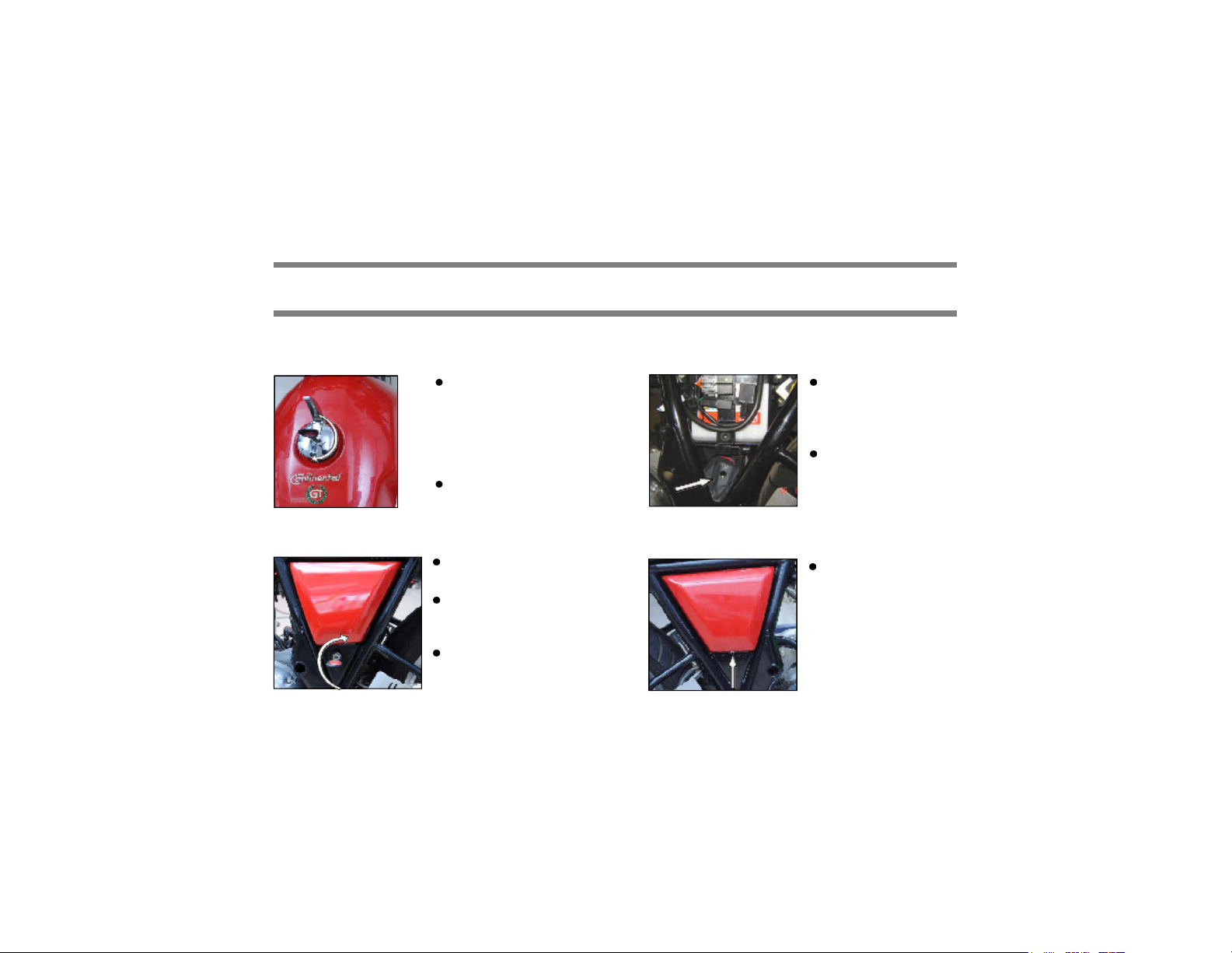
FUEL TANK CAP
Turn key clockwise
to open. Press the
cap to lock with key
in position.
NOTE :
Key can be removed
only in locked position.
SIDE PANEL LH / BATTERY COVER
Turn key clockwise to
unlock the side panel.
Pu ll th e s i de pan el
outside for opening
the same.
Ke y cann ot b e
remo v ed in t his
position.
UTILITY BOX
Utility box i s
pr ov i d ed at t h e
bot tom ar ea of
battery carrier.
It is c ov e r ed wit h
side panel LH
SIDE PANEL RH
Unscrew the indicated
screw and then pull
t he side pane l f or
opening the same.

Operation of Controls
28
ALPHA-NUMERIC DISPLAY UNIT
This unit in the
speedometer consists
of
1. Odometer
Alpha Nume ric Display
Push Bu tton
Sw itch
2. Trip A
3. Trip B
4. Fuel level indicator
ODOMETER MODE
Odomet er mode is t he
initial display mode of
this un i t . It di s p lays
od om e t er read i ng by
def ault.
NOTE :
Once you turn “ON” the ignition key, whatever was the
last selec tion mode will get displayed.
TRIP METER MODE
A light push for les s
tha n one sec o n d on
the “PUS H” but t o n
switch will change the
display from odometer
to Trip meter (TRIP A)
Again another press on the “PUSH” button switch
will change the display f rom “TRIP A to “TRIP B”.
NOTE :
For resetting the Trip Meter
1. Set the display as TRIP A or B as a current mode.
2. Press the “PUSH” button f or more than 3 Seconds.
3. Automatically the display will become zero.
Warning
Do not attempt to change any setting while riding the
motorcycle. It may cause loss of control leading to an
acc ident .

Operation of Controls
29
FUEL LEVEL INDICATOR
The fuel level in dic ator
indicates the level of fuel
in the fuel tank.
The display bar s of the fu el met er di sappears
t ow ar d s t h e E m p t y ( E ) w h en t he f ue l leve l
decreases .
when last bar start blinking (less than 3 litres), refuel
the bike at the earliest.
NOTE :
If the last bar of the fuel meter is blinking continuously
after fueling, visi t a Royal Enfield authorised dealer
and check the same.
BATTERY LOW VOLTAGE INDICATOR
Battery low voltage indicator
If the battery voltage is less than 12 volts, the low
voltage indicator will s tart glowing continuously.
W hile the ignition is “ON” , low voltage indicator
symbol will glow until engine reaches 700 RPM.
In running condition if the battery voltage is below
12 Volts for more than 3 seconds continuously, the
low voltage indicator will start glowing.

Operation of Controls
HEAD LAMP SWITCH
30
HEAD LAMP OFF
PRESS FOR HEAD LIGHT FLASH
POSITION LAMP
DIP SWITCHHEAD LAMP DAY FLASH
LOW BEAM
HEAD LAMP ON
HIGH BEAM

Operation of Controls
31
ENGINE START SWITCH
TURN SIGNAL SWITCH
OFF (PUSH TO OFF)
PRESS
ENGINE STOP SWITCH
ENGINE ON
LEFT RIGHT
ENGINE OFF

Operation of Controls
32
HORN
MANUAL BI STARTER (CHOKE)
PRESS
Apply choke in cold start condition while starting the Bike

Pre Operational Checks
33
A careful check of the following must be carried out
every time before riding and specially after long periods
of storage to determine if any additional maintenance
is necessary.
1. Adequate fuel in the tank.
2. Tyres for correct pressure, abrasions or cut s.
3. Rear chain for proper tension and suffic ient
lubrication.
4. Brakes, s t eer ing a nd t hr ot t le f or pr oper
responsivenes s.
5. Cable for fraying or crimping and free operation.
6. Engine oil level.
7. W heel spokes for proper tigh tnes s and no
breakage.
8. Headlamp, tail lamp, brake lamp and indicator
lamps for proper functioning.
Warning
For your pers onal welfar e and saf ety, all the point s
mentioned above should be perf or med periodi cally.
Failure t o do so may affec t saf e operation, d amage
your mo tor c yc le and co uld res ult in an ac c ide nt
caus in g serious injury.

Running In Period
34
Proper ru nni ng-I n is very imp or t an t for obtain ing
maximum life and performance of a new motorcycle.
The following guid elines explain p roper runnin g- in
pr oc edu res .
Since the engine is brand new, it should not be loaded
excess ively for the first 2 ,000 kilometers. During the
fir st few hundred kilometers, the mating parts in the
engine will wear and polish themselves to the c orrect
operat ing cl ea ran ces . Dri vin g wit h prolonged ful l
throttle operat ion, or in any hig h speed cond it ions
migh t result in excess ive heating of the engine and
cause abnormal wear of the moving parts and hence
the same must be avoided.
1. 0-500 Kms :
T h e rec om m ende d s p eed s f or t he fi r s t 5 0 0
Kilometer s is below 50 to 60 Kmph. During this
per iod avoid operat in g the motorc yc le wit h ful l
throttle opening. Stop the motorc ycle f or about 5
to 10 minutes to let it cool down, after every hour
of ru nni ng. Vary th e sp eed of the motorcycle
reg ular l y du ring r unni n g but avoid us i n g th e
motorcycle above 1/2 throttle opening p osition.
2. 501-2000 Kms :
The recommended s peed is below 80 – 90 kmph.
Avoid drivi ng the motor c yc le wi th ful l throttl e
op enin g . Vary t h e s p eed o f t h e m ot o r c yc l e
reg ularly but avoid using the motorcyc le above
th
3/4
t hrottle opening position.
3. 20 01 Kms and above
Avoi d pr ol on g ed f ul l - th r ott l e ope r ation. Var y
sp eed occasi onall y.
CAUTION :
After covering the first 500 kilometers, Please replace
the engine oil and oil filter element.
Roy al E nf i eld engi ne s ar e air-c oo l ed and
conseq uently requir e forc ed air coo lin g over th e
cyl in der an d he ad to ma i ntai n pr oper op er at i ng
tem perature. Ext ended periods of idling may over
heat the engine, resulting in serious engine damage.
DO NOT run the engine at extremely high RPM with
cl ut ch disengag ed or trans mis s ion in neutral as it
can caus e serious engine d amage.
An engine runni ng for long distanc es at high speed
must be given clos e attention to avoid overheati ng
and possi ble engine damage

Electronic Fuel Injection (EFI)
35
ELECTRONIC FUEL INJECTION (EFI)
An electronic control unit (ECU) monitor s engine
performance and provides exact requirement of Air
/ Fuel mixture to the engine, through the fuel injector
by taking inputs from various sensors provided in
the motorcycle.
THE ADVANTAGES OF EFI ARE
Faster response of the engine to suit road/load
condit ions.
Better power output
Lower emission
Bett er reliability
Excellent cold Startability
Engine Diagnost ic capabilit ies
Maintenance f ree
MALFUNCTION INDICATOR LAMP (MIL)
A M alfunc t i onin g
Indicator Lamp (MIL)
is provid ed in the
RPM meter which is
located on the right
side of the Cluster
unit.
1. EFI Mal Funct i on Indicator : W hen bot h the
Ignition & Engine kill switch is “0N”, the MIL will
glow for fe w sec onds and will go “OFF ”. This
indicates that all the func tions of Electronic Control
Unit (ECU) and other sens ors are working perfectly
and the motorcycle can be used.
In case of any malfunctioning of the ECU or other
sensors etc., the MIL will glow continuously. In the
event of any such phenomenon, it is recommended
to take the vehicl e to a near est Royal En field
authorised service point for inspection and further
neces sary action.

Rollover Sensor
36
ROLLOVER SENSOR
Your motorcycle is fitted with a unique “Roll Over
Sensor” under the seat. T his is a safety feature.
In the event of an accident OR if the motorcycle
falls over on any side with the eng ine run ning
condit ion, The “Roll Over Sensor” will switch off
Ignit ion and cut off fuel su ppl y to pr event the
motorcycle from moving suddenly, while it is in gear.
To re-activate the system after the motorcycle has
been made upr igh t, please sw itc h off both the
Ignition & Engine kill swit ch, wait for a few s econds
and switch “ON” again.
This will help to RESET the “Roll Over Sensor” and
the engine can be started/ run.

Starting
37
Warning
Before starting engine, always shift gears into neutral.
CAUTION :
Do not force the gear lever while attempting to shift to
ne u t r al . Move th e motor c yc l e ba c k & for th and
simult aneously press gear lever to come to neutral.
Ensure neutral Indicator light glows in the Speedometer.
NOTE :
If the engine does not start on the first attempt
in cold climate, release the starter button, wait
for 30 seconds before pr es s ing the starter
button again.
Press starter button and release starter switch
once the engine starts.
A clutc h swit ch is provided in the sys tem for
the safety of the rider. This is to prevent the
vehicle from starting when the vehicle is in gear.
To start the engine when it is in gear, pull clutch
lever, press th e st arter but t on and releas e
slowly after the engine starts.
Tu r n ignit io n
switch ‘ON’
Ensure the side
and main stands
are in releas ed
pos ition
Ensure that gears
are in neutral and
neutral lam p is
glowing

Starting
38
Ensur e Engin e
stop switch is in
“RUN” position
Press Clutch
Lever.
Press Starter
Button and
release as soon
as engine starts
CAUTION :
Never acc elerate the engine immediately after a cold
start. The engine should be allowed to run slowly f or
15-30 seconds. This will allow the engine to warm up
and let oil reach all sur f ac es n eed ing lubri c ation.
Failure to adhere may result in damage to the Engine.
Manual bi
Starter (choke)
NOTE :
It may be necessary to operate and hold the manual
bi starter, when starting the engine f or the first time in
cold mornings , temper atures below 10°C or at high
altitudes, to prevent the stalling and to keep the idling
RPM steady.

Starting
39
As so on as the engin e at t ains t h e oper at ing
temperature, the RPM will raise, at which time the
manual Bi Starter should be released.
Warm up engine for 2 minutes - till idling is
cons is tent.
Prior to st arting, check to see the f uel level from
the fuel gauge.
If the last bar is blinking refuel immediately.
CAUTION :
Please ens ure the motor cycle is not used with the
low fuel indic ator bar blinking continuously. It may not
only result in the motorcycle running out of fuel. But
will also cause s er ious damage to the f uel pu mp.
Please ensure f uel is filled up as s oon as the low fuel,
last bar start blinking.
CAUTION :
Air cooled engin e req ui r es air movement over the
cylinder head and exhaust pipe to maintain proper
oper ati ng temperature.
Never accelerate the engine abnormally in stand still
condition of the motorcycle. Failure to adhere this may
res ult in damag e to exhaust pipe / si lenc er of the
engine due to over heating.

Gear Shifting
40
Warm up engine
for 2 minutes t ill id ling i s
consistent/stable
GEAR SH IF T PAT T E R N
1 N 2 3 4 5
Press clutc h lever towards the hand grip.
Press gear pedal with toe toward s down to
engage 1st gear.
Gen t l y op en t hr ot t l e a n d r el eas e c lu t c h
simultaneously. If clutch is released suddenly,
the engine may stall and cause a jerky s tart.
CAUTION :
The clutch must be fully disengaged before attempting
a gear shift. Failure to fully disengage the clutch may
cause a jerk y start OR stallin g the engin e besides
caus ing damage to transmi ssion parts.
Press the gear
pedal upwards
wi t h t oe t o
en g ag e 2n d
and gear.
Follow the same procedure for 3rd, 4th and 5th
gear.
NOTE :
Always start motorcycle with gear in neutral position.
Always move the motorcycle in f irs t gear position only.
W hen engin e speed decreases or while c li mbing a
gradient or running at a reduced s peed, shift to the
appropria te lower gear to prevent the eng ine fr om
stalling or straining to pull.

Parking
41
PARKING VEHICLE ON CENTER STAND
Select a firm, flat surface
Hold handle bar straight
Lower center stand, and ensure that both the
legs of the stand are resting evenly on firm ground.
Apply pres s ure on the fulcru m lever on the
center stand and pull vehicle upwards, gently.
PARKING VEHICLE ON SIDE STAND
Select a firm, flat surface
Lower Side Stand and gently tilt motorcycle to
the left till it rests firmly on the side s tand.
Warning
Always park the m otor c ycle on a firm and flat surface. Parking in a soft ground may cause stand to s ink and the
motorcycle to f all, c ausing injury to you or to others and damage t o the motorcycle parts.

Tools & First Aid Kit
42
2 3 4 5
1
S.No. Description Qty.
1. Tool Bag 1
2. Screw Driver O6 X 160 1
3. Tommy Bar 1
4. Box Spanner 21 X 24 1
5. Double End Spanner 14 X 15 1
6. Double End Spanner 10 X 13 2
7. Double End Spanner 8 X 10 1
8. Allen Key 5 MM 1
9. Allen Key 3 MM 1
10. Tyre Removal Lever 2
6 7
8
9
10
5
4
S.No. Description Qty.
1. Antiseptic cream 5 gms 1
2. Gauze bandage 5 cm x 2 cm 1
3. Elastic Gauze bandage 8 cm x 1 mtr. 1
4. Wash proof plaster 1.9 c m x 7.2 cm 2
5. Sterilized Gauze Swab 5 cm x 5 cm 2
6. Sterilized elastic plaster 7 cm x 6 cm 1
7. First aid kit pouch 1
3
6
1
7
2
NOTE :
This Tool Kit is kept in Utility box. Refer Page No. 27.

Recommended Lubricants
43
Engine Oil
Grade Royal Enfield 15 W 50 API SL Grade
Engine Oil
(JASO MA)
Capacity 2.75 Ltrs. (for dry fill)
2.50 Ltrs. (during oil & filter element
replacement)
Front Fork Oil
Grade Royal Enfield
Front Fork Oil
(or Gabriel Fork
Oil 2W 35)
Capacity 430 ml / leg
ISO 14001 – EMS
Operation Control Process
1. All customers are advised timely replacement of Engine Oil,
Fork Oil & Brake Oil at the dealership /ASP. In case done
privately, it is advise to reach old/used Oil to our authorised
vendor through RE Dealer/ASP
2. Similarly we advise for disposal of old/used Battery, Tube &
Tyres as mentioned in above point No.1.
Grade DOT 3 or DOT 4
Capacity
Warning
DO NO T swit ch oil brands indiscriminat ely because s ome oil i nteract chemic ally when mixed.
Use of i nferior oils or non- deter gent oils can damage the engine.
DO NOT Mix DOT 3 & DOT 4 brake fluid together.
Brake Fluid
Front : 50 ml
Rear : 100 ml

Periodical Maintenance
The maintenance schedule detailed here will help you to maintain your Royal Enfield motorcycle meticulously and to
get a long trouble free service. The schedule provided herein is based upon average riding conditions and indicates
the mileage at which regular inspections, adj ustments, replacements and lubrications must be carried out.
The frequency of the maintenance must be shortened depending upon the severity of the Riding condition OR if the
motorcycle is used in a very dusty environment, severe climatic cold and hot conditions, bad roads, stagnant water
etc., Contact a nearest Royal Enfield Authorised Dealer / Service Point for expert advice and to carry out the
periodical maintenance.
44
Warning
For your personal welf are, all the listed service and maintenance recommendations should b e performed. Lack of
reg ular mai nt en ance at the s u gges t ed intervals m ay aff ec t t he safe operati on of your motorcycl e cau s in g the
motorc ycle to malf unc tion and st all abruptly resulting in an accident and cause s erious injur y.
A : Adjust C : Clea n D : D e-c arbonise I : Ins pect L : Lubr ica te R : Rep lace
NOTE :
For maintenance after 30,00 0 Kms, pleas e repeat the s ame frequency levels specif ied ab ove, in consultation wit h a
Royal Enfield Authoris ed Dealer / Service Point.
Do not mix DOT 3 and DOT 4 brake fluid together.
*Carbo cleaner / Carbclik or Fuel Line Cleaner Spray. (Make - Wurth or ITW Chemin)

Periodical Maintenance
45
S.
No.
Kms (x 1000) 0.5 3 6 9 12 15 18 21 24 27 30
Months 1.5 3 6 9
1 Engine Oil
2 Engine oil filter element R C R R R R R
3 Engine sump filter (oil strainer) C C C C C C C
Magnetic drain plug under gear box and secondary
4
drain plug under
5 Spark plug C&A C&A C&A C&A C&A R C&A C&A C&A C&A R
6 HT lead for crack I I I I I I I I I I I
7 Fuel hose & clip / Injector ‘O’ Ring / Seal Ring I I I I R I I I R I I
8 Fuel Pump Check for screw tightness in all services
9 Accelerator & Throttle pully cable free play A A A A A A A A A A A
10 Rubber hose, Air filter to Throttle body I I I I R I I I R I I
11 Rubber hose, Inlet manifold I I I I R I I I R I I
DESCR IPTION
cranksharft in
crankcase RH
FREE SERVICE
whi chever is ea rlier
R R R R R R
Check level at every 1000 Kms or earlier as required
C C C C C C C
PAID SERVICE

Periodical Maintenance
46
S.
No.
Kms (x 1000) 0.5 3 6 9 12 15 18 21 24 27 30
Months 1.5 3 6 9
12 Air filter paper element C C C C R C C C R C C
13 Inlet / Exhaust valve seating I I
14 Cylinder head (Combustion chamber) D
15 Exhaust pipe D
16 Clutch lever free play Adjust every 1000 Kms or earlier as required
17 Rear brake pedal pivot L L L L L L L L L L L
18 Battery terminals (apply petroleum jelly) C C C C C C C C C C C
19 Battery Electrolyte level I I I I I I I I I I I
20 Earth wire eyelet contact (below ECU Mounting) I I
21 Rear Wheel Drive Chain
22 Front Fork oil / leak I I I R I I I R I I I
23 Steering ball races / play adjustment A L A R A L A R A L
DESCR IPTION
FREE SERVICE
whi chever is ea rlier
Adjust every 1000 Kms or earlier as required
Lubricate every 3000 Kms or earlier as required
PAID SERVICE

Periodical Maintenance
47
S.
No.
Kms (x 1000) 0.5 3 6 9 12 15 18 21 24 27 30
Months 1.5 3 6 9
24 Spokes tightness / Wheel rim run out front & rear I I I I I I
25 Rear wheel cush rubbers I & R I & R
26 Tyre wear front & rear I I I I I I I I I
27 Hand levers & Kick starter pivot Lubricate every 1000 Kms or earlier as required
28 Brake Oil level check / Replacement I I I I I I I I R I I
29 Pivot-Side Stand / Center Stand pivot L L L L L L L L L L L
30 Rider & Pillion Foot rest pivot L L L L L L L L L L L
31 Swing arm needle bearings and spindle L L
32 Vent Pipe under air filter box I & C I & C I & C I & C I & C I & C I & C I & C I & C I & C
33 Throttle body - cleaning spray* C C C C C
34 PAV pipes & hose clip I I I I I I I I R I I
35 Front & Rear brake hose and Banjo Bolt I I I I I I I I I I R
DESCRIPTION
FREE SERVICE
whi chever is ea rlier
PAID SERVICE

Minor Maintenance Tips
48
The following minor maintenance can be carried
out easily with simple tools. However, In case, if it
is felt that the adjustments are best done by an
expert, we recommend that the motorcycle be taken
to a nea res t Royal Enfi eld Aut horis ed Dealer /
Service Point.
CONTROL CABLES, HANDLE BAR LEVER, PIVOTS,
CENTER / SIDE STAND PIVOTS
Main Stand Pivot
Lever Pivot
Lubricate after using the motor cycle in rain,
after waterwash or if us ed in dusty conditions.
Wipe the area free of dirt / grease.
Apply a few drops of oil on the pivots.
Side Stand
Pivot
OIL LEVEL INSPECTION
MAX
MIN
Place motorcycle on its center stand on a firm
surface.
Warm up engine for a few minutes & switch off.
The level is correct if the oil level is in the middle
of the oil level window.
Top up with recommended oil if required.

Minor Maintenance Tips
ENGINE - OIL CHANGE
Place motorcycle on its centre stand on a firm
flat surface.
Start engine and warm up for 2 minutes.
Keep a clean tray below the engine
49
TILT VEHICLE RH & LH
Prim ary
Drai n
Plug
(Refer Periodical Maintenance Chart for frequency)
Remove primary drain cap, to drain oil & clean
suction filter, magnet.
Then remove secondary drain plug to drain oil &
clean the magnet.
Finally remove primary drain bolt to d rain the
complete oil.
Prim ary
Fil ter Cap
Sec ond ary
Drai n P lug
Remove the oil filter paper elem ent on the
Crankcase Cover RH.
Allow the oil to drain by tilting the motorcycle to
both sides.
Wash the primary and secondary drain plugs
along with suction filter thoroughly and refit on
the crankcase after all the oil is drained out.

Minor Maintenance Tips
50
Soak a new oil filter paper element in the oil and
refit on the Crankcase Cover RH.
Assembly 3 bolts and tighten them. Ensure ‘O’
Ring and gaskets are taken seat properly.
Fill recommended
oil to engine till the
oil lev el is upt o
“MAX” level mark in
the oil window in
Crankcase Cover
RH.
Max
NOTE :
Replace oil filter paper element whenever oil is being
repl ac ed.
Min
CAUTION :
Do not f ill oil over “MAX” mark. It may cause the engine
to smoke and result in loss of power. Do NOT use the
motorc ycle if the oil is below the “MIN” mark. Doing
so will caus e serious damage to the movin g par ts
inside the engine and result in an engine lock up.
SPARK PLUG
Gap 0.80 to 0.90 mm.
Cl ean ing an d adj usting gap ( Ref er Periodic al
Maintenance Chart f or frequency)
Remove HT Lead and the spark plug from the
cyl inder head usin g the plug sp anner and
Tommy bar.
Clean the insulator tip and electrodes of the plug
carefully using a pointed sc raper or spark plug
cleaner.
Set the gap between 0.80 to 0.90 mm.
Refit the spark plug on the cylinder head and
connect H.T. Lead.

Minor Maintenance Tips
51
BRAKE FLUID
MAX
MIN
MIN
FRONT BRAKE REAR BRAKE
Check if oil is below ‘MIN’ level. To top Up, remove
cover and diaphragm, then top up with DOT 3 or
DOT 4 as specified.
CAUTION :
Brake fluid is highly corrosive and can caus e damage
to painted parts. Please ensure that brake fluid does
not spill on any part of the motorcycle. In the event of
a spill, please c lean the area immediately with a soft
cloth ( preferably a wet cloth) to avoid damage.
Don’t mix DOT 3 & DOT 4 Brake fluid together.
INSPECTION OF TYRES AND WHEELS
Inspect the tyre periodically for
tread wear, cracks and cuts.
Minimum tread depth
Front tyre : 1.00 mm
Rear tyre : 2.00 mm
Check and remove stone, splinters, nails or other
particles embedded in the tyre treads.
Bald spots / swelling may be caused by internal
damage. Replace the tyres, if defective.
Replace tyres when the tread depth has reached
the minimum as specified.
Periodically ins pect wheels for spokes breakage
and wheel rim run out.
Check proper s eating of the tyre beading on the
rim whenever the tyre is reassembled.
Whenever a new tyre is installed, ensure rim
and s pokes do not get damaged on account of
wrong handling.

Minor Maintenance Tips
52
Us e only stand ard tyres & tubes inflated to
correct pressure.
TYRE PRESSURE
Front Rear
Solo 1.41 kg/cm2 2.11 kg/cm2
(20 PSI) (30 PSI)
With Pillion 1.55 kg/cm2 2.25 kg/cm2
(22 PSI) (32 PSI)
Warning
Tyres, rims and air valves must be correctly matched
to w hee l r i m s . S ee your Roy al E n f i eld D ealer.
Mismatching tyre, tubes, rims and air valves may result
in damage to the tyre bead during mounting, allow
tyre slippage on the rim and cause tyre failur e.
FRONT WHEEL REMOVAL
Place the vehicle on center stand
Place a wooden block
t he f r ont e nd of
engine to support the
vehicle.
Loosen the pinch bolt
on the RH fork guide
by 6 mm allen key.
Hold the axle head by
dou ble end span ner
wh ile loosenin g th e
axle nut.
Remove the axle nut
along with washer.

Minor Maintenance Tips
53
Tap and remove the
front wheel spindle.
Tilt the vehicle to RH
Locating
TAB
Side and take out the
wheel alo n g w it h
wheel speed sensor
and LH side spacer.
CAUTION :
Do not pres s the fron t brake lever when wheel is
removed as this will result in the brake pads c oming
too f ar out of the brake caliper.
Place a 4 mm thick wooden piece or cardboard
sheet between the brake pads to avoid pads
activation in the event the front brake lever is
accidently pressed.
FRONT WHEEL REASSEMBLY
Remove the wooden piece / card board sheet
placed between the brake pads
Place the wheel speed
sensor in position.
Ensure slot on hub
and speedo sensor is
matched correctly.
Ins ert th e whee l
al ong wi t h w h eel
speed sensor and LH
spacer between the
fr ont f ork en d s
ens uring the brake
di s c i s lo c a t e d
between the br ak e
pads.
In s ert and tap th e
f r ont w h eel axl e
gently inside.
Refit the washer and
tighten the nut firmly.

Minor Maintenance Tips
Tighten the pinch bolt on the RH fork guide.
Rotate the wheel and check for smooth rotation.
REAR WHEEL REMOVAL
Index mark
54
Place the vehicle on
cen t er st an d on a
firm and flat surface.
Observe and mar k
the alignment index
ma r k s in the both
sides of swing arm.
Remove axle nut on
the RH side.
Ensure wheel speed sensor wire coupler is being
connected to c lus ter unit and then check for
proper working of speedo meter.
Press brake lever 2 or 3 times to check front
brake efficiency.
Remove wheel spindle
from LH side along
with wheel collar and
LH side spacer.

Minor Maintenance Tips
55
Remove the calip er
ass emb ly by pulling
out from the swing
arm slot.
Remove the distance collar.
Tilt the motorcycle towards RH side and take out
the rear wheel assembly conveniently.
CAUTION :
Do not press the r ear brake pedal when wheel is
removed as this will result in the brake pads c oming
too far out of the brake c aliper.
Place a 4 mm thick wooden piece or cardboard
sheet between the brake pads to avoid pads
activation in the event the rear br ake pedal is
accident ly pressed.
REAR WHEEL REASSEMBLY
Ensure the four Cush rubbers are in position
inside the rear wheel hub.
Tilt vehicle to right and
insert wheel assembly
be t w een the swin g
arms.
Po s i t i on t h e r ea r
wh eel with c u s h
rubber on t he r ear
dr iven f l a nge /
adaptor.
Fix the LH side spacer
in rear wheel hub.
Remove the wooden
pi ec e / card b oar d
sheet placed between
the brake pads.

Minor Maintenance Tips
In s er t the c al i per
assembly by pushing
in th e pr o j e c t io n
giv en i n s id e t he
swin g ar m. Ensur e
the br a ke d isc is
locat ed in bet ween
the brake pads.
Align the caliper brack et, wheel and swing arm
holes in-line and ensur e dis t an ce collar is
placed in hub dus t seal.
Insert and tap the rear
wheel axle gently.
CAUTION :
Do not force the spindle into
the wheel as the thr ead s
may get damaged. Tap it
through the wheel gently.
Ensure the index marks alignments on both sides
of the swing arm are in same position for proper
wheel alignment.
56
Adjuster End Plate
Index mark
Adjuster Lock nut
Tight en the axle nut
firmly.
Ensure that swing arm
end plate is seated
prope r l y and th e
ch ain adj u s ter nut s
ar e correc t ly tight -
Warning
Ensure the vehicle do not c ome out of center s tand
wh i l e d i s m antlin g an d as sem b l i ng the whe el
assemb ly.
ened and Locked.

Minor Maintenance Tips
57
ADJUSTMENTS - CLUTCH LEVER FREE PLAY
2 to 3 mm
Clutc h Lever (free play 2 - 3 mm)
Loosen the cable outer lock nut (A).
Turn the Nut (B) Clockwise to reduce the play
or Anticlockwise to increase the free play.
Check free play 2 to 3 mm at Clutc h lever pivot
on handle bar end.
Tighten lock nut (A) after adjustment is done.
B
REAR BRAKE LIGHT SWITCH ADJUSTMENT
The brake light glows once
you press the brake pedal.
If brake light is not glowing,
check the brake light switch
A
If above are alrig ht , then do the adjustm ent as
mentioned below:
1. Turn the brake light switch adj ustment nut while
holding the rear brake light sw it ch bod y in
position.
2. If the brake light do not glows after press ing
th e pedal for approxim at ely 25mm , tur n the
adjusting nut in clockwise direction by 2 to 3
threads and check for brake light function.
3. If the b rak e light continuous ly glows,turn the
adjusting nut in anti clockwis e direction by 2
to 3 threads so as to get the positions in which
the light goes off.
wire for proper connection
and the brake light Switch
sp ring f or any bend,
breakage or disconnection.

Minor Maintenance Tips
58
DRIVE CHAIN FREE PLAY (PLAY 20 - 25 MM)
Plac e m ot or -
Dri ve c hain slack
adjusting nut
Ind ex mark
Swing Arm
reference m ark
1. If the drive chain free play is incorrect adjust
as follows:
a. Loosen the axle nut of the rear wheel axle.
Ad ju st e r
Lock nut
c yc l e o n its
center stand on
a fi r m & f l at
surface.
Sh ift the gear
into t he neutral
pos ition
Me as u r e t h e
drive chain free
play as shown.
The drive chain
free play is 20 to
25 mm
b. L oosen the Q D
sprocket spindle nut.
c. Loosen the locknut at
bo t h end o f the
swing arm.
d. To reduc e the free
play, turn the drive
chain slack adjusting
nut i n cl oc k w i s e
direction.
e. To increase the free
play, turn the drive
chain slack adjusting
nut in anticlockwise
direction and pus h
t h e r e a r w h e e l
for war d .

Minor Maintenance Tips
59
f. Later adjust the nut on LH side by matching
the index mark with respect to RH side index.
g. Ensure that both the sides are in same index
marks.
h. Finally torque the spindle and axle nuts to 7
kgm.
i. Tighten the adjuster locknut by 13mm spanner
against chain slack adjusting nut.
Warning
Ch ai n slacknes s beyond 30m m w ill lead to ch ai n
slippage.
Main tai n drive ch ain s lacknes s wit hin the spec if ied
limits at every 1000 kms interval.
Please Check the front and rear wheels are correctly
aligned, after the c hain adjustment.
CHAIN LOCK FITMENT
The open end of the chain master link lock should
face opposite to normal direction of chain rotation.
Warning
The f itment of loc k in wrong directi on other than
shown above can lead to its falling off, and thus can
caus e the sudden disconnection of the c hain during
the drive.

Minor Maintenance Tips
60
ADJUSTMENT OF GAS FILLED SHOCKABSORBER
Th e rear gas f i lle d shoc k ab s or ber is an
adjus t ab le type.T he sp ring tension can be
increased or decreased.
Reduce the spring tension for low load operation
by turning the adjuster nut in the direction as
shown above by using a suitable C - spanner.
In c r eas e th e sp r ing tens ion for hi gh load
operation by turning the adj uster nut in oposite
direction.
Adjust both the rear shock absorbers to the same
thread possitions.
Recommended = 10 mm height adj ustment only
from factory setting.
Warning
Rid ing th e motor c yc l e wit h the sh ock ab s or b er s
adju ste d in diff erent pos i tions can ca us e l os s of
contr ol.
Regularly inspect s hock absorbers and front forks for
any leaks.
NOTE :
Ens ure acc essories, f itted if any, do not foul with
rear shoc k ab s orbe r s . Ch eck fo r su f f i c i ent gap
between the shock absorbers and the attachment s
in a condition that the rear end of the Motorcycle is
fully loaded and the shock absorbers are maximum
compressed .

Minor Maintenance Tips
61
REMOVAL OF BATTERY FROM THE VEHICLE
Battery Carrier bracket screw
(-)
TERMINAL TERMINAL
Unlock (turn the key clockwise) and remove
the Left side panel.
Disconn ect both the ter minal wires (negative
first and positive next respectively)
Rem o v e th e batt ery c ar rier b r a c k et b y
loosening the two screws
Take out the battery.
BATTERY MAINTENANCE
(+)
The Motorcycle is provided with 12V - 14 AH
battery.
The battery must be periodically checked for
Cleanliness and corrosion free terminals.
Electrolyte level.
I f elect r oly t e level is low, top up with
distilled water only.
NOTE :
The poor contact or loose fitment of Battery terminals
may cause ECU failure.

Minor Maintenance Tips
62
Warning
Always d isc on ne c t the neg at ive (-) batt ery cab le
fi r s t and th en th e Red pos iti ve (+) c abl e wh i l e
removing the battery connecti ons .
NOTE :
For chec k ing the batt er y vol tag e a nd elec trolyt e
sp ec if ic gravity, co nt act aut h orised Roy al Enf ield
Dealer / service point or battery service centre.
CAUTION :
Do not use battery with low electr olyt e level as
the battery internal cells will get damaged.
Do not overf ill the battery electr olyte level as it
will s pill out through the overflow pipe and cause
corrosion to vehicl e parts.
Use only distilled water meant for use in batteries
to avoid damage to battery.
REASSEMBLY OF BATTERY ON MOTORCYCLE
Position the battery in the battery carrier such
that negative terminal of the battery is towards
the fuel pump side.
Ensure ignition swit ch is
in “OFF” condition.
Con n e c t t he p os it iv e
terminal (Red wire) first
Con n e c t t h e n egat iv e
terminal (Black wire) next.
Smear the term inals with petroleum jelly. (Do
not use grease in the battery terminals).
Place the terminal boot / cap properly.
Refit the carrier bracket.
Refit LH side panel & lock it.
NOTE :
Clean t he wire terminal s free of corros ion and keep
the terminals coated with petroleum jelly.
CAUTION :
Keep the +ve and -ve cables f irmly conneted t o the
res pective bat tery t erminals . Failur e to do so may
result in damage to the motorcycle electrical system.

Minor Maintenance Tips
63
CHANGING ELECTRICAL COMPONENTS
HEADLAMP BULB REPLACEMENT
Loo s en the r i m
holdi ng sc r ew on
top and tak e ou t
the h ead l amp
dom e.
Disconnect electrical connections.
Thumb push and
remo v e th e bu lb
ho ld ing c lam p
gently.
Remove the bulb.
Po s i t i on new b u l b
in s id e the reflec t or
such that the three
project ions o n t h e
bulb align with the slot
on the reflector.
Refix the bulb holding
clamp.
Connect the Electrical
connections.
Position head lamp doom onto the head lamp
shell and tighten the mounting screw on top.
NOTE :
Never touc h t he bulb with your
fi n gers . Finger pr ints will etc h
the glass and decrease bulb life.
Always hold the bul b with paper or clean dr y cloth
during handling as s hown in f ig.
X

Minor Maintenance Tips
64
TAIL LAMP BULB REPLACEMENT
Unlock the bat tery
cover
Re m o ve t he s eat
assembly by pulling
seat lock cable.
Re m o ve t he t a i l
lig h t g la s s by
uns cr ew ing i t s
mounting screw
Hol d t h e b u l b , press insi de and r ot at e
anticlockwise to remove the tail light bulb from
its holder.
Replace the bulb 12V 21 / 5W.
A s s e m b l e
back the tail
light in th e
r e v e r s e
or der of
disman tling
process.

Minor Maintenance Tips
65
TRAFFICATOR BULB REPLACEMENT
Remove t he scr ew
from the trafficator
housing back side.
Open the Indicator
hous ing.
Take out the bulb
holder with help of
is screw driver.
Take out the bulb
an d r eplac e th e
same.
Ref it the h older
fitt ing it s l o c k in
proper position.
Fix the rubber gasket
cover.
Assemble back the
in d ic at or hous i ng
cover.

Minor Maintenance Tips
66
FUSE
1
2
3
4
5
8
7
6
Warning
Electronic Cont rol U ni t (ECU) may fail due to loose
elect rical connections, loose bat tery t erminal s etc.
Henc e, it is very important to keep all the Electrical
connec tions intact .
BLADE FUSE USAGE LIST
Fuse
Color
No .
1 Blue 15A RR Fuse
2 Blue 15A MAIN Fus e
3 Re d 10A EC U Fuse
4 Re d 10A
5 Re d 10A Head Lam p Fuse
6 Re d 10A Instrument Cluster / Horn
7 Blue 15A Spare Fuse
8 Re d 10A Sp are Fuse
Amps
Gene ra l illu mina t io n / Tail / Tra f fi c at or
Application
Warning
Please get the electrical system of your Motorcycle checked
th ro ug ht ly and get the faul ts corr ected im media tly aft er
experiencing any fuse failure. Not doi ng this c an result in to
repeated fuse failures.
Usage of fuses other than spcified rating will damage the complete
electrical system.
Warning
While doing Arc welding any where in motorcycle,the battery
terminals and the Electronic Control Unit (ECU) coupler are to be
completely disconnected. Failure to do so many cause damage to
the Electrical system of the Motocycle.

Minor Maintenance Tips
67
AIR FILTER PAPER ELEMENT
CLEAN AND REFIX : EVERY 3000 KMS
Remove the screw from the side cover bottom
side and then take out RH side cover.
Remove the air filter
cover sc rews and
then takeout air filter
box cover.
Takeout air filt er pap er element and check
for dirt. Gently tap it as shown in fig and fix it
back.
NOTE :
It is adviceable to replace air filter paper element once
in 10,000 KMS. In case of vehicle running in dusty /
mud road condition it may be r eplaced as earlier as
req uired.
Us age of h i gh pres sure c om p r es sed ai r is not
recommended to clean air f ilt er paper element.
Fitment of air filter paper element is reverse order of
removal p rocess .

Washing Procedure
68
PRECAUTIONS
Wash vehicle when t he engine is cold.
Cover the silencer tail end and contr ol switches
with suitable plastic bags and tie it firmly to prevent
water entry into them.
Remove ignition key and seal k ey hole using
adhesive tape.
Do not rem ove RH side cover (panel) while
washing to avoid water entry into air filter box
assembly.
X
Use a suitable engine degreaser, available with
your local parts store, to remove dirt or grease
from the engine external parts if required. Follow
the directions in the label carefully before using
the degreaser.
Use low pressure jet of water to clean the entire
vehicle.
Never spray water with great force on head lamp,
Meter/cluster unit, trafficator lights, front and rear
wheel hubs, electrical connections and w ires,
control cables, EFI components, spark plug ,
battery,air fillter cover etc.
Use Luke warm water and mild detergent on the
painted components to remove dirt, etc.
Rinse vehicle thor oughly with plain water to
remove the detergent and wipe vehicle dry.
If possible, use compressed air and blow off
water par t icles fr om the obs c ure ar eas of
t he v ehic le, e lec tr i c al c o n n e c t i o ns , EF I
components etc.

Washing Procedure
69
AFTER WASHING
Ensure the vehicle is thoroughly dry by wiping
with a clean soft water absor bent cl ot h or
chamois leather.
Remove all plastic bags and adhesive tapes.
Lubricate control cables, pivots for footrest, side
st and, cent re stand, brake and gear shifter
linkages, rear c hain etc.with lube oil.
Polish the painted and plated surfaces using
polishing wax.
Start the bike and allow engine to idle & warm up.
Drive the motorcycle slowly, applying both brakes
intermittently to dry up the brake pads.
Test brakes for full efficiency.
Warning
Observe war nings and cau tions given on labels of
cleaning compounds before it is used.
When washing your motorcycle, be careful not to get
the brakes , engine, muff lers or air cleaner et c. , too
wet. Wet brake pad and / or disc can aff ect braking
eff ic ie nc y. En gine can be star ted after was h i ng.
Ensure brakes and engine are working properly bef ore
riding in the traffic and / or in highways at high speeds.

Storage Precautions
70
Incase your Motorcycle is not going to be used for
a m onth o r m or e, w e advise t h e foll o w ing
precautions to be taken
Carryout required repair/adj ust ments on the
motorc ycle.
Wash the motorcycle t horoughly and lubricate
as per the maintenance chart.
Start the engine, warm up f or a few minutes
and switch off.
Drain out the fuel completely from the fuel tank
and fuel lines.
Remove the spark plug. Pour in about 20ml of
clean engine oil through spark plug hole. Close
the hole and crank engine few times and refit
the sparkplug.
Clean the rear chain thorough ly and apply
lubrication oil on it.
Re m ove bat t e r y from th e bi k e . Clean i t s
terminal s and apply petr oleum jell y on the
terminals to avoid c orrosion.
Maintain electr olyte level between max and
min marks, by adding distilled water and wipe
the battery dry.
Stor e the bat t ery in a cool , dry and wel l
ventilated place.
Do not place the battery in direct sun light, near
open flame or where temper at ur e is above
40°C or below 0°C
Cover the silencer with plastic bags to prevent
moisture entry. Set the motorcycle on its center
stand.
Apply anti rust solution on all chrome plated
parts. Take care not to apply this solution on
rubber or painted parts .
Store motorcycle in a clean covered area free
of moisture and keep it covered to prevent dust
settling on it.

Storage Precautions
71
PREPARING THE MOTORCYCLE FOR REUSE
Remove anti rust solut io n from all ch rome
plated parts and clean the motorc ycle.
Inflate the tyres to the correct tyre pressure.
Ensure battery is fully charged and electrolyte
level is properly maintained.
Connect the bat tery.
Lubricate all control cables and pivots.
Ch eck level of oil in engi ne and top up if
necess ary.
Fill fuel tank with fresh petrol.
Check fuel line for any cracks or cuts.
Clean the air filter.
Remove plastic covering from the silencer.
Remove spark plug on c ylinder head and pour
in a few drops of engine oil. Crank engine a
few times to lubricate cylinder walls and piston.
Clean spark plug and refit.
Switch “ON” the ignition swit ch.
Start vehicle and warm up engine for a few
minutes before riding the vehicle.
NOTE :
Do not raise the engine rpm the moment it is started,
but allow the engine to run at Idling speed.
CAUTION :
Proper long-term stor age i s imp ort ant for the saf e,
tr oub l e-f r ee o per a t ion o f you r R oyal E n f i eld
motorcycl e.

Long Trip Precautions
72
CHECKS PRIOR TO THE COMMENCEMENT OF LONG
JOURNEY
Ser vice the motorc yc le thor ough ly at Royal
Enfield Authorised Dealer / Service Point as per
periodical maintenance chart. (Ref. Page No. 45
to 47)
Sufficient quantity of petrol in the fuel tank for
the planned journey.
Check and correct tyre pressure if necessary.
Correct the oil levels in Engine, brake master
cylinders .
Check for good battery condition and proper
electro lyte level.
Pr oper dr iv e ch ain ten s ion and c orr ect ly
adjusted rear brakes.
Check for proper functioning of all lights & horn
etc.,
CHECKS AFTER EVERY 1500 KMS OF RUN
Tightness of all fasteners.
Tyre treads condition and wear pattern of tyres.
Battery condition and electrolyte level.
Correct oil level in engine.
Working of all lights and horn.
Proper drive chain tension.
ITEMS TO BE CARRIED
Tool kit.
First aid kit.
Bulbs for Headlight, Trafficator light and mini
Blade Fuses (15 & 10 Amps).
Accelerator and Clutch cable.
Rear chain master link lock assembly.
Spare tubes.
Foot operated Air Pump.
Insulation tape.
Spark plug (M14).

Complete Wiring Diagram
NOTE :
Complete W iring Diagram is attached on this page.
73

NOTE
SG - SENSOR GROUND
PG - POWER GROUND
LG - LOGIC GROUND
CG - CHASSIS GROUND
EG - ENGINE GROUND
RG - RR BODY GROUND
F 6 - 10A - INST CLUSTER / HORN
F 7 - 10A - SPARE FUSE
F 5 - 10A - HEAD LAMP FUSE
F 3 - 10A - ECU FUSE
F 2 - 15A - MAIN FUSE
F 1 - 15A - RR FUSE
F 8 - 15A - SPARE FUSE
F 4 - 10A - GENERAL ILLUMINATION
/ TAIL / TRAFFICATOR
FUSE DETAILS
BLACK/GREEN
RED/WHITE
WHITE/RED
YELLOW
PUMP RELAY
2 PIN
WATER PROOF
COUPLER
2 PIN
WATER PROOF
2 PIN
WATER PROOF
FUEL
PUMP
INJ
BLACK
SPARK PLUG
IGNITION
COIL
3 PIN (6 POLE)
WATER PROOF
COUPLER
ORANGE
ORANGE
BROWN
ORANGE
ORANGE
POWER RELAY
BLACK / GREEN
BLACK / WHITE
BLACK
K-LINE
GREY
BLACK
MAGNETO WITH
CRANK POSITION SENSOR
WHITE
2 PIN
WATER PROOF
COUPLER
3 PIN
WATER PROOF
COUPLER
3 PIN
WATER PROOF
COUPLER
2 PIN
WATER PROOF
TPS
MAP
TE
ROLL
OVER
SENSOR
BLACK
3 PIN (4 POLE)
WATER PROOF
COUPLER
PIN NO. 34(NLSW) PIN NO. 1(IGP)
PIN NO. 3 (CRK-P)
PIN NO. 9 (CRK-M)
PIN NO. 6 (PM)
PIN NO. 22 (TE)
PIN NO. 2 (ROLL)
BLACK
PIN NO. 13 (VCC)
PIN NO. 5 (TH)
PIN NO. 24 (SG)
PIN NO. 11 (FLPR)
PIN NO. 16 (INJ)
PIN NO. 18 (IG)
PIN NO. 10
(K-LINE)
PIN NO. 21 (MIL)
PIN NO. 35
PG 1
PIN NO. 36
PG 2
PIN NO. 20
(TEST)
PIN NO. 8
(LG)
ECU WITH CONNECTORS
24T
BLACK
ECU FUSE
FUSE 3-10A
FUSE 4-10A
GREY
BLACK
BLACK/GREEN
BLACK/WHITE
BLACK
RED/WHITE
RED/WHITE
HORN LT
HORN HT
RED/WHITE
NEUTRAL SWITCH
BROWN
IGNITION
SWITCH
OFF
POSITION
2X6.3MM COUPLER
RH
LH
BLACK/WHITE
BLACK/GREEN
FRONT TRAFFICATORS
RED
RED/WHITE
RED
BLACK
BLACK
BLACK
BLACK/GREEN
REAR BRAKE
SWITCH
GREY
GREY
BLACK/WHITE
BLACK/GREEN
YELLOW
YELLOW/RED
BLUE
BLACK
GREY
GREY
GREY
BLUE
BLACK
GREEN
BLACK
BROWN
FUSE 6-10A
FUSE 5-10A
5
6
7
2
3
4
8 9
1
9X2.8
COUPLER
RED
WHITE
RED / WHITE
YELLOW / WHITE
YELLOW
YELLOW
SWITCH MODULE LH
2X2.8 COUPLER
2X2.8 COUPLER
2X2.8 COUPLER
NATURAL
0.9 KW STARTER MOTOR
TRAFFICATOR
REAR RH
RELAY STARTER
BLACK
GREEN
GREY
BLACK/
BLACK
TAIL/STOP
LIGHT
WHITE
TRAFFICATOR
REAR LH
6X2.8 COUPLER
2X6.3 ‘L’ TYPE
COUPLER
GREEN
GREEN
RED/WHITE
BLUE/WHITE
LIGHT GREEN
RED
BROWN
THREE
PHASE
MAGNETO
24T
RED/WHITE
FLASHER
BLACK
YELLOW
2X6.3 COUPLER
3X6.3 COUPLER
RED
RED
BLACK
BLACK
RG
CG
EG
12V 14AH
BATTERY
BLACK
RECTIFIER
REGULATOR UNIT
(THREE PHASE)
FUSE 1-15A
FUSE 2-15A
TANK UNIT
MAX
MIN
SPEED SENSOR-BLUE/WHITE
PULSAR COIL - GREEN/WHITE
PULSAR COIL - WHITE
BATTERY - RED
MIL - BLACK/GREEN
HIGH BEAM - BLUE
NEUTRAL - BROWN
TRAFFICATOR RH-BLACK/GREEN
TRAFFICATOR LH-BLACK/WHITE
GENERAL ILLUMINATION-GREY
NEGATIVE - BLACK
POSITIVE - RED/WHITE
FUEL GAUGE-WHITE/YELLOW
BLACK
CLUTCH SWITCH
HEAD LIGHT
60/55W-HALOGEN
SWITCH MODULE
FRONT
BRAKE
SWITCH
9X2.8
COUPLER
RED/WHITE
BLUE/WHITE
BLACK/YELLOW
G
H
E
F
C
A
B
D
WHEEL
SPEED
SENSOR
BULLET
TERMINAL
SG
LG
PG
Complete Wiring Diagram - Continental GT

Trouble Shooting
74
Warning
The trouble shooting section of this Owner’s Manual
is intended solely as a guide f or diagnosing problems.
Carefully read the appropriate s ections of this manual
before performing any work. Repair and maintenanc e
operations not list ed in this Owner ’s Manual should
be per f orm ed by you r Royal Enf i el d Deal er on ly.
Impr oper repair / main tenan c e could res ult in the
motorcycle not f unctioning properly or injury seriously.
Warning
Please get the electrical system of your Motorcycl e
chec ked th r ou ghtl y and g et th e faults corre c t ed
immediatly after experiencin g any fuse f ailure. Not
doing this can result in to repeted f use failures.
Usage of f uses other than spcified rating will damage
the complete electrical system.
CAUSES REMEDIES
I. ENGINE FAILS TO START
1) Stop switch in ‘OFF’ Position ............. Push stop switch to ‘ON’ position.
2) Vent hole clogged in fuel tank cap .... Clean vent hole.
3) Spark plug cap / lead not connected . Fix cap / lead firmly
4) Spark plug electrode dirty / fouled .... Clean spark plug
5) Spark plug insulation cracked ........... Replace spark plug
6) Clutch slipping ................................... *Adjust clutch cable free play
7) Main or EFI Fuse failed................... .. Replace with new fuse
* Contact Authorised Dealer / Service Point

Trouble Shooting
CAUSES REMEDIES
II. ENGINE MISFIRING
1) Loose spark plug cap ........................ Fix cap / lead firmly
2) Spark plug fouled .............................. Clean spark plug or non s pecified heat range plug.
3) Any sensor loose connections ......... * Check MAP or EOT or TPS sensor wiring / coupler loose connections
4) W ater in petrol tank ........................... * Clean petrol tank. Fill tank with fresh petrol.
III. POOR PICKUP
1) Brake pedal adjusted too tight ........ *Re-adjust properly
2) Choked air filter ............................... Clean / Replace air filter
3) Rear chain adjusted too tight .......... *Re-adjust properly
4) Under inflated tyres ......................... *Inflate to correct pressure
5) Acc elerat or cable free play excessive Adjust cable free play
6) Clut ch S lipping ................................. *Adj ust c lutch cable free play
7) Faulty fuel supply ............................. *Remove fuel pump & c lean.
Fuel pump, filter / injector blocked
* Contact Authorised Dealer / Service Point
75

Trouble Shooting
CAUSES REMEDIES
IV. WHITE/BLUE SMOKE
1) Oil level in sump above the Top line. * Check and drain excess oil
in the oil level window .....................
V. ENGINE OVERHEATING
1) Low engine oil level ......................... Check and top-up if necessary
2) Clut ch s lipping ................................. * Check and correct
3) Cylinder fins not clean ..................... Clean the cylinder fins at regular intervals
VI. EXCESSIVE FUEL CONSUMPTION
1) Under inflated tyres ......................... Inflate to correct pressure
2) Choked air filter ............................... Clean / Replace
3) Fuel leakage ..................................... *Check and rectify, tank float unit, drain pipe, breather pipe,
.......................................................... fuel line / pump.
* Contact Authorised Dealer / Service Point
76

Trouble Shooting
CAUSES REMEDIES
VII. BRAKES POOR
1) Brake pad worn / Uneven wear ....... *Replace Brake pads
2) Oil/g rease on disc. ........................... *Clean and refit
3) spongy brake .................................... *fill brake fluid & remove air from t he system.
VIII. VEHICLE WOBBLES
1) Under inflated tyres ......................... Inflate to correct pressure
2) Loose / Broken spokes .................... * Tighten / Replace spokes
3) W heels misaligned .......................... * Ensure proper alignment
4) W heel rim runout ............................. * Rectify
5) Tyres not fitted correctly .................. * Refit tyres correctly
IX. ELECTRICALS
Bulbs do not glow
1) Bulb fused ........................................ * Replace bulb
* Contact Authorised Dealer / Service Point
77

Trouble Shooting
78
CAUSES REMEDIES
2) Fuse blown ....................................... * Check and Replace fuse.
3) Loose / improper connection ........... * Check and correct
Horn not working
1) Fuse blown ....................................... Check and correct
2) Loose connections ........................... Check and correct
Trafficators not working
1) Loose / improper connections ......... Check and correct
2) Bulb fused ........................................ Replace
Brake light remains on
(1) Switch not adjusted properly .......... * Adjust c onnecting links properly
(2) Switch stick y .................................... * Replace switch
Warning
Please get the electrical system of your
Motorcycle checked throughtly and get the
fau l ts c orrecte d im m ed iatly after
experiencing any fuse failure. Not doing
this can result in to repeated fuse failures.
Usage of fuses other than spcified rating
will damage the complete electrical system.
X. ELECTRONIC FUEL INJECTION (EFI)
Malfunctioning Indicator Lamp (MIL) glow ing continuously
(1) Sensor Coupler Loose Connection . * Check for any EFI sensor coupler loose connection and correct them
(2) Any EFI Sensor Failure ...................... * Check & replace the same
* Contact Authorised Dealer / Service Point

Warranty
Royal Enfield Motor Cycles are manufactured by following best Quality practices in respect of the material and
workmanship.
Royal Enfield (RE) warrants CONTINENTAL GT EFI Motor Cycle to be free from manufacturing and material defect
under normal use subject to following conditions.
1. RE will replace or repair defective part / parts at their Authorised Dealer / Service Point, free of charge within a
period of 12 months from the date of sale (date of Installation) or 10,000 kms whichever occurs earlier.
2. The warranty is applicable only to f irst registered owner.
3. The warranty shall be applicable only if all the free services are availed at the respective period / kilometer range
as per the schedule given in the owner’s manual from RE Authorised Dealer / Service Point.
4. During the warranty period, RE’s obligations shall be limited to repairing / replacing free of charge such part or
parts of the vehicle, which on examination to have manufacturing defect. Such defec tive part / parts which have
been replaced becomes property of RE.
5. Cost of oil, oil filter, fuel and other consumables are chargeable to the customer.
6. Claims on proprietary items like tyres, tubes, spark plug, battery etc. should be taken up with respective
manufacturer or their authorised agents in the area directly by customer. RE shall not be liable in any manner to
replace them though their Dealers will provide assistance in preferring such claims on their manufacturer.
7. W arranty shall not apply to:
(a) Normal ageing, detoriation or rusting of plated parts paints coat, rubber parts, soft items, glass items, plastic
parts etc.
79

Warranty
(b) Components like fuel line, oil f ilter element, control cables, brake shoes, clutch plates, which are subjected
to normal wear and tear.
(c ) Damages due to use of lubricant / oil / grease etc., other than specified by RE.
(d) Damages due to use of non-genuine parts.
(e) Damages due to lack of proper maintenance of the vehicle.
(f ) Damages due to incorrect driving or riding habits.
(g) Parts damaged due to accidents, collision, abuse etc.
(h) Irregularities not recognized as affecting the quality or function of the vehicle such as slight vibration, oil
leakage, discoloration of exhaust bent pipe / silencer / soft or hard shock absorber etc.
(i) Defects arising from fitment of unauthorised / additional Electrical loads.
(j) Vehicle serviced / repaired at unauthorised service points.
(k) Vehicle used for competition / racing.
(l) Electrical component like bulbs, f uses etc. & Electronic components failure due to repairs by arc welding.
(m) Normal maintenance operations like adjustment of brakes, cleaning f uel system, engine tune up and other
such adjustments
8. RE reserves the right to finally decide on all warranty claims
9. RE reserves the right to make changes in Design of the vehicle without any obligation to install these changes on
previously supplied vehicles.
80

Emission Warranty
In compliance with the provisions of Rule 115(2) of the Central Motor Vehicle Rules, 1989, Royal Enfield certifies that
the following warranty is applicable to those components liable to affect the emission of the gaseous pollutants in its
range of motorcyc les, in normal use to which it may be subj ected to.
This emission warranty comes into force from 01st July 2001 and is valid for a period of 30,000 Kms. or 36 months,
whichever occurs earlier, from the date of sale to the first customer and is in addition to and parallel to the warranty
policy, conditions and obligations laid down in the Owner ’s Manual.
Royal Enfield further warrant y that if on examination by its Authorised Dealer / Servic e Point, the motorcycle fail to
meet the s pecified emission s tandards, then the Authorised Dealer / Service Point shall take necessary corrective
measures and shall at its sole discretion, repair or replace free of charge such components of the emission control
system to meet the required emission standards.
The method/s of examination to determine the warranty conditions of the emission warranty related components will
be at the sole discretion of Royal Enfield and / or our Authorised Dealer / Service Point and results of such examination
will be final and binding. If on examination the warranty conditions of the part/s is/are not established, Royal enfield
will have the right to charge all, or part of the cost of such examination to the customer in addition to the cost of the
components.
In case of acceptance of the component/s under Emission warranty, Royal Enfield will replace free of c harge, the
component/s as required. However, t he consumables like fuel, lubricants, solvents, etc shall be chargeable to the
customer as per actual.
In case any of the c omponents covered under emiss ion warranty or the associated parts, are not independently
replaceable. Royal Enfield will have the sole discretion to replace either the entire assembly or parts of the assembly,
through suitable repairs.
81

Emission Warranty
Royal Enfield reserves the right to carry out necessary consequential repairs to the motorcycle or replace any part,
in addition to the repair or replacement of the components covered under emission warranty, to establish compliance
to in-use emission standards. Such repairs / replacements will be chargeable to the customer.
All parts removed for replacement under warranty will become the property of Royal Enfield.
Royal Enfield will not be respons ible for the cost of transportation of the motorcycle to the nearest Authorised Dealer
/ Service Point OR for any loss due to non availability of the motorcyc le during the period of examination and repairs
by Royal Enfield and / or their Authorised Dealer / Service Point.
Royal Enfield will not be res ponsible for any penalties that may be charged by statuatory authorities on acc ount of
failure to comply with the in-use emission standards.
That cost/s incurred to check emission of the motorcycle will have to be borne by the customer.
Emission warranty will be applicable irrespective of the change of ownership of the vehicle provided all the conditions
as laid down in this document are met from the date of original sale of the motorcycle.
82
THE WARRANTY SHALL APPLY IF THE CUSTOMER
Observes all the important instructions and any other precautions listed in the owner’s manual.
Under all c ircumstances uses lubricants and fuel as recommended by Royal Enfield.
Regularly obtains and carries out maintenance in accordance with Royal Enfield guidelines and enters the details
in the Log book.
Immediately approaches the nearest Authorised Dealer / Service Point upon discover y of failure to comply with
the IN-USE emission standard inspite of having maintained and used the vehicle in accordance with the instructions
in the owner’s manual and having carried out such repairs and adj ustments as may be required with a view to
establish such compliance.

Emission Warranty
Produce the ‘Pollution Under Control’ certificate valid for the period immediately preceding the test during which
the failure is discovered, the test having been carried out either for obtaining a new certificate or pursuant upon
being directed by an officer as referred to in sub rule (2) of rule 116 of the Central Motor Vehicles Rules (CMVR).
Produce the Owner’s Manual and Log book for verification details .
Produce receipts covering maintenance of the motorcycle is specified in the owner’s manual from the date of
original purchase of the vehicle.
Produce valid certificate of Insurance and R.T.O. Registration Certificate (RC Book).
THE EMISSION WARRANTY SHALL NOT APPLY IF
A valid “Pollution under control” certificate is not produced.
The motorcycle is not serviced by Authorised Dealer / Service Point as per the service schedule described in the
maintenance chart.
The motorcycle has been subjected to abnormal use, abuse, neglect and improper maintenance or has met with
an accident.
Replacement parts not specified and approved by Royal Enfield have been used.
The motorcycle, or parts thereof, has been altered, tampered with or modified or replaced in an unauthorised
manner.
The odometer is not funct ioning or the odometer and / or its reading has been changed / tampered with, so that
the actual distance covered cannot be readily determined.
The motorcycle has been used for competitions, races, and rallies or for the purpose of establishing records.
83

Emission Warranty
On examination by Royal Enfield or its Authorised Dealer / Service Point, if the motorcyc le shows that any of the
conditions stipulated in the Owner’s manual with regard to use and maintenance have been violated.
The motorcycle has been run on adulterated / leaded fuel or lubricant other than those specified by Royal Enfield
in the Owner’s manual or any other document given to the customer at the time of sale of the motorcycle.
The emission related components are tampered with.
All service and parts related bills and vouchers incurred during the tenure of the emission warranty is not produced.
All maintenance activities carried out on the vehicle during the tenure of the emission warranty is not entered in
the log book.
84
TIPS TO BE ON THE RIGHT SIDE OF LAW
Always get your vehicle checked to meet the emission regulations through and authorised emission checking centre.
Always carry a valid ‘Pollution Under Control’ certificate with you at all times during the validity of the emission
warranty (30,000 Kms / 3 years from the date of first sale)
TIPS TO REDUCE POLLUTION
1. Ensure that the periodical maintenance is carried out as stipulated in the owner’s manual through a Royal Enfield
Authorised Dealer / Service Point.
2. Use only Unleaded petrol (> 91 oct ane) from reputed fuel pumps.
3. Ensure the fuel used is not adulterated.
4. Use correct spark plug as recommended in the owner’s manual.
5. Use lubric ants as per recommendations given on grade / brand in the owner’s manual.

Regional & Area Offices
85
R1 : Chandigarh, H.P, J&K,
Punjab
Royal Enfield
SCO5, 1 st Floor , 11 Sector,
PANCHKULA (Haryana)
Pin Code - 1 34 113.
Ph: 0172-5011255, 5011251
R2 : Delhi, Haryana, NCR &
Rajasthan
Royal Enfield
C/o EICHER ENGG.COMPONENTS
Plot No. 7, HSIDC Industrial Area,
Sector 18, Palam Gur gaon Road,
GURGAON (Haryana) – 122 015.
Ph: 0124-4278138 / 4278139
Fax: 4382148
Royal Enfield
G-5, 6, 7, Gitanjali Tower s,
Ajmer Road, JAIPUR – 302 006.
Ph: 0141-4106747, 4034748
Fax: 0141-4106748
R3 : Bihar, Uttaranchal &
Uttar Pradesh
Royal Enfield
UGF-109, Cross Road Plaza,
Badshah Nagar Chauraha,
Near Flyover, Faizabad Road,
LUCKNOW – 226 006.
Ph: 0522-4004640, 6569352
Fax: 4005973
R4 : Assam, N.E. & West Bengal
Royal Enfield
C/o V.E.Commercial Vehicle Ltd.
1st Floor, P.S.Tower,
No.13, Bondel Road,
KOLKATA - 700 019.
Tel: 033-40060206 / 0209
R5 : Gujarat & M.P
Royal Enfield
Safal Prelude,
103, Opp. Parshwanath
Esque Cross Road,
Corporate Cross Road,
Off. S.G. Highway,
AHMEDABAD - 380 015.
Ph: 098-25113168
Fax: 079-40024461
R6 : Goa & Maharashtra
Royal Enfield
Plot No.16, Sector -1,
Sion Panvel Highway, Nerul,
NAVI MUMBAI - 400 706.
Ph: 022-27700395, 27700501
Royal Enfield
203, 204 Sneha Ganga,
Near Vega Centre,
Shankar Seth Road, Swargate,
PUNE - 411 037.
Ph: 020-40028090
Fax: 24447174
R7 : A.P, Chattisgarh,
Jharkhand & Orissa
Royal Enfield
Plot No. 3,
Kandukuri Business Chambers,
Sunder Nagar Colony,
Beside ESI Hospital,
Erragadda,
Hyderabad - 500 038.
Ph: 040 - 40213540
Royal Enfield
A Unit of Eicher Motors Ltd.
407, 4th Floor, Nirmala Plaz a,
Forest Park,
BHUBANESWAR - 751 009.
Ph: 0674 – 6540206
R8 : Karnataka, Kerala,
Tamilnadu & Puducherry
Royal Enfield
Plot No. 350 to 354,
2nd Floor, 4th Link Street,
Nehru Nagar Industrial Area,
Kottivakk am,
(OMR-IT Highway),
CHENNAI- 600 096.
Ph: 044-42070661, 24540828
Royal Enfield
Door no. 2067/1, 2068/ 2,
East End “A” Main
9th Block, Jay anagar,
BANGALORE - 560 069.
Ph: 080-22440588, 41753277,
41536488
Royal Enfield
25/85A, Opp. to IOC Pump,
Koonamthai, Edappally Post,
KOCHI - 682 024.
Ph: 0484-6494990, 6494991
Fax: 2543616

Free Service Coupons
It is our endeavour to provide excellent service to your Royal Enfield Motor Cycle at all times. Towards this we provide
four free services at specific Intervals.
Please avail these services at the specified time, in any of the Royal Enfield Authorised Dealer / Service Point nearest
to you and as a token of satisfactory service, kindly return the free service coupon duly filled in and signed, to the
service outlet.
Availing the free services in the specified time is a prerequisite to warranty consideration.
The cost of fuel, oil, oil filter element, grease etc. used for f ree service is chargeable to the customer.
86

1st Free Service
87
ST
1
FREE
SERVICE
500 Kms
or
45+8 days
whichever is
earlier from the
date of sale
Enter the Details
in Free Service
Record
(Cost of oil,
oil filter element
and other
consumables
used are
chargeable to
the customer)
500 KMS OR 45+8 DAYS WHICHEVER IS EARLIER FROM DATE OF SALE
Customer Name : Dealer Code :
Add res s :
Fra me No:
Engine No:
Vehicle Installation Form No.
ODO Reading :
Sold by (Dealer’s Name & Address)
Received the above vehicle after the service having been done to my entire satisfaction.
Customer’s Signature : ................... .............. Date :
Contact Phone / Mobile No.:
Reg n. No:
Sale Date:
Serviced Date:
Servic ed by
(Dealer’s/ASP Name & Address)

1st Free Service Activities
88
1. Water wash the vehicle and dry it with a clean cloth
2. Electrolyte ........................................................ Check level & top-up
3. Battery terminals ............................................. Clean and apply petroleum jelly
4. Drive chain free play........................................ Check, clean, lubricate & adjust
5. Rear brake pedal pivot ..................................... Lubricate
6. Front & Rear disc brakes ................................ Check & top up brake fluid level
7. Wheel rim Front & Rear ................................... Check spokes tightness
8. Front fork oil ..................................................... Inspect for leakage
9. Air filter element ............................................... Clean
10. Spark plug (M14) .............................................. Check, clean & adjust gap
11. H.T. Lead.......................................................... Inspect for cracks
12. Fuel pump ........................................................ Check mounting screws
13. Fuel hose ......................................................... Inspect for cracks
14. Rubber hose, Air filter to throttle body.............. Inspect for cracks
15. Accelerator cable ............................................ Adjust play
16. Clutch cable ..................................................... Adjust play
17. Engine oil sump strainer ................................... Clean
18. Engine oil.......................................................... Replace
19. Engine oil filter paper element .......................... Replace
20. Hand levers & kick starter pivot........................ Lubric ate
CUSTOMER COPY
Job Card No:
Date :
Odo Reading :
Name of Dealer/
ASP with Code:
........................ ..
........................ ..
ASP / Dealer’s
Stamp & Signature

2nd Free Service
89
ND
2
FREE
SERVICE
3000 Kms
or
90+15 days
whichever is
earlier from the
date of sale
Enter the Details
in Free Service
Record
(Cost of oil,
oil filter element
and other
consumables
used are
chargeable to
the customer)
3000 KMS OR 90+15 DAYS WHICHEVER IS EARLIER FROM DATE OF SALE
Customer Name : Dealer Code :
Add res s :
Fra me No:
Engine No:
Vehicle Installation Form No.
ODO Reading :
Sold by (Dealer’s Name & Address)
Received the above vehicle after the service having been done to my entire satisfaction.
Customer’s Signature : ................... .............. Date :
Contact Phone / Mobile No.:
Reg n. No:
Sale Date:
Serviced Date:
Servic ed by
(Dealer’s/ASP Name & Address)

2nd Free Service Activities
90
1. Water wash the vehicle and dry it with a clean cloth
2. Electrolyte ........................................................ Check level & top-up
3. Battery terminals .............................................. Clean and apply petroleum jelly
4. Drive chain free play........................................ Check, clean, lubricate & adjust
5. Rear brake pedal pivot ..................................... Lubricate
6. Front & Rear disc brakes ................................ Check & top up brake fluid level
7. Wheel rim Front & Rear ................................... Check spokes tightness
8. Front fork oil ..................................................... Inspect for leakage
9. Air filter element ............................................... Clean
10. Spark plug (M14) ............................................. Check, clean & adjust gap
11. H.T. Lead.......................................................... Inspect for cracks
12. Fuel pump ........................................................ Check mounting screws
13. Fuel hose ......................................................... Inspect for cracks
14. Rubber hose, Air filter to throttle body.............. Inspect for cracks
15. Accelerator cable ............................................ Adjust play
16. Clutch cable ..................................................... Adjust play
17. Engine oil.......................................................... Check level & top up
18. Hand levers & kick starter pivot........................ Lubricate
19. Steering free play ............................................ Check & Adjust
Oil filter element, oil strainer & magnetic drain plugs
20.
.. Clean
CUSTOMER COPY
Job Card No:
Date :
Odo Reading :
Name of Dealer/
ASP with Code:
........................ ..
........................ ..
ASP / Dealer’s
Stamp & Signature

3rd Free Service
91
RD
3
FREE
SERVICE
6000 Kms
or
180+15 days
whichever is
earlier from the
date of sale
Enter the Details
in Free Service
Record
(Cost of oil,
oil filter element
and other
consumables
used are
chargeable to
the customer)
6000 KMS OR 180+15 DAYS WHICHEVER IS EARLIER FROM DATE OF SALE
Customer Name : Dealer Code :
Add res s :
Fra me No:
Engine No:
Vehicle Installation Form No.
ODO Reading :
Sold by (Dealer’s Name & Address)
Received the above vehicle after the service having been done to my entire satisfaction.
Customer’s Signature : ................... .............. Date :
Contact Phone / Mobile No.:
Reg n. No:
Sale Date:
Serviced Date:
Servic ed by
(Dealer’s/ASP Name & Address)

3rd Free Service Activities
92
1. Water wash the vehicle and dry it with a clean cloth
2. Electrolyte ...................................................... Check level & top-up
3. Battery terminals ............................................. Clean and apply petroleum jelly
4. Drive chain free play ....................................... Check, clean, lubricate & adjust
5. Rear brake pedal pivot .................................... Lubri cate
6. Front & Rear disc brakes ................................ Check & top up brake fluid level
7. Wheel rims front & rear.................................... Check spokes tightness
8. Tyre front & rear ............................................ Check wear and tread depth
9. Air filter element .............................................. Clean
10. Spark plug (M14) .............................................. Check, clean & adjust gap
11. H.T. Lead ......................................................... Inspect for cracks
12. Fuel pump ........................................................ Check
13. Fuel hose ......................................................... Inspect for cracks
14. Rubber hose, Air filter to throttle body ............. Inspect for cracks
15. Accelerator cable ............................................ Check & adjust play
16. Clutch cable .................................................... Adjust play
17. Engine oil sump strainer .................................. Clean
18. Engine oil ......................................................... Replace
19. Engine oil filter paper element .......................... Replace
20. Hand levers & kick starter pivot ....................... Lubricate
21. PAV System ................................................... Check & Clean
22. Steering system ...............................................
Check, Lub. steering balls & Adj. play
CUSTOMER COPY
Job Card No:
Date :
Odo Reading :
Name of Dealer/
ASP with Code:
........................ ..
........................ ..
ASP / Dealer’s
Stamp & Signature

4th Free Service
93
TH
4
FREE
SERVICE
9000 Kms
or
270+15 days
whichever is
earlier from the
date of sale
Enter the Details
in Free Service
Record
(Cost of oil,
oil filter element
and other
consumables
used are
chargeable to
the customer)
9000 KMS OR 270+15 DAYS WHICHEVER IS EARLIER FROM DATE OF SALE
Customer Name : Dealer Code :
Add res s :
Fra me No:
Engine No:
Vehicle Installation Form No.
ODO Reading :
Sold by (Dealer’s Name & Address)
Received the above vehicle after the service having been done to my entire satisfaction.
Customer’s Signature : ................... .............. Date :
Contact Phone / Mobile No.:
Reg n. No:
Sale Date:
Serviced Date:
Servic ed by
(Dealer’s/ASP Name & Address)

4th Free Service Activities
94
1. Water wash the vehicle and dry it with a clean cloth
2. Electrolyte ....................................................... Check level & top-up
3. Battery terminals ............................................ Clean and apply petroleum jelly
4. Drive chain free play ....................................... Check, clean, lubricate & adjust
5. Rear brake pedal pivot .................................... Lubri cate
6. Front & Rear disc brakes ................................ Check & top up brake fluid level
7. Wheel rims front & rear.................................... Check spokes tightness
8. Front fork oil ..................................................... Replace oil
9. Air filter element ............................................. Clean
10. Spark plug (M14) ............................................. Check, clean & adjust gap
11. H.T. Lead ......................................................... Inspect for c racks
12. Fuel pump ........................................................ Check
13. Fuel hose ......................................................... Inspect for cracks
14. Rubber hose, Air filter to throttle body ............. Inspect for cracks
15. Accelerator cable ............................................ Check & adjust play
16. Clutch cable .................................................... Adjust play
17. Engine oil ....................................................... Check & top-up
18. Hand levers & kick starter pivot ....................... Lubricate
19. Steering free play ............................................ Check & Adjust
20. Tyres ................................................................ Check wear and tread depth
CUSTOMER COPY
Job Card No:
Date :
Odo Reading :
Name of Dealer/
ASP with Code:
........................ ..
........................ ..
ASP / Dealer’s
Stamp & Signature

Paid Service / Maintenance Record
95
CUSTOMER COPY
12,000 + 250 Kms. Service
Job Card No :................. Date : .........................
Odo Reading : ................. Dealer Code : .............
Brief W ork D one :
Dealer’s Stamp & Signature
CUSTOMER COPY
15,000 + 250 Kms. Service
Job Card No :................. Date : .........................
Odo Reading : ................. Dealer Code : .............
Brief W ork D one :
Dealer’s Stamp & Signature
DEALER / ASP COPY
12,000 + 250 Kms. Service
Job Card No :................. Date : .........................
Odo Reading : ................. Dealer Code : .............
Brief W ork D one :
Dealer’s Stamp & Signature
DEALER / ASP COPY
15,000 + 250 Kms. Service
Job Card No :................. Date : .........................
Odo Reading : ................. Dealer Code : .............
Brief W ork D one :
Dealer’s Stamp & Signature

Paid Service / Maintenance Record
96
DEALER / ASP COPY
12,000 + 250 Kms. Service
Brief W ork D one :
Dealer’s Stamp & Signature
DEALER / ASP COPY
15,000 + 250 Kms. Service
Brief W ork D one :
Dealer’s Stamp & Signature
CUSTOMER COPY
12,000 + 250 Kms. Service
Brief W ork D one :
Dealer’s Stamp & Signature
CUSTOMER COPY
15,000 + 250 Kms. Service
Brief W ork D one :
Dealer’s Stamp & Signature

Paid Service / Maintenance Record
97
CUSTOMER COPY
18,000 + 250 Kms. Service
Job Card No :................. Date : .........................
Odo Reading : ................. Dealer Code : .............
Brief W ork D one :
Dealer’s Stamp & Signature
CUSTOMER COPY
21,000 + 250 Kms. Service
Job Card No :................. Date : .........................
Odo Reading : ................. Dealer Code : .............
Brief W ork D one :
Dealer’s Stamp & Signature
DEALER / ASP COPY
18,000 + 250 Kms. Service
Job Card No :................. Date : .........................
Odo Reading : ................. Dealer Code : .............
Brief W ork D one :
Dealer’s Stamp & Signature
DEALER / ASP COPY
21,000 + 250 Kms. Service
Job Card No :................. Date : .........................
Odo Reading : ................. Dealer Code : .............
Brief W ork D one :
Dealer’s Stamp & Signature

Paid Service / Maintenance Record
98
DEALER / ASP COPY
18,000 + 250 Kms. Service
Brief W ork D one :
Dealer’s Stamp & Signature
DEALER / ASP COPY
21,000 + 250 Kms. Service
Brief W ork D one :
Dealer’s Stamp & Signature
CUSTOMER COPY
18,000 + 250 Kms. Service
Brief W ork D one :
Dealer’s Stamp & Signature
CUSTOMER COPY
21,000 + 250 Kms. Service
Brief W ork D one :
Dealer’s Stamp & Signature
 Loading...