


EURO IV - VEHICLE SERVICE MANUAL
Continental GT
Bullet EFI
Classic Bullet EFI
KS MOTORCYCLES - http://ksmotorcycles.com

ROYAL ENFIELD VEHICLE SERVICE MANUAL - EURO IV
1
PREFACE
“FIRST TIME RIGHT” is a very important element for enhancing Customer Satisfaction.
Royal Enfield is committed to upgrade the skills and knowledge of technicians so that they follow scientific repair
techniques to ensure “FIRST TIME RIGHT” practices and carry out repairs accurately so that customers will enjoy
trouble free performance at all times.
This Maintenance and service manual is specifically for the following EURO IV Regulation models being currently sold
only in UK & European countries.
BULLET EFI
BULLET CLASSIC EFI
CONTINENTAL GT
This Manual is intended for use primarily by a person who is well versed with basic repair technique of a motorcycle
& usage of general purpose tools and special service tools & diagnostic tools, while basic & routine service maintenance
may be in the event of not having possibility in carrying out using basic tools, required tools it is recommended that
the motorcycle may please be get inspected and serviced through an Authorized Royal Enfield Service Station.
This manual will help in guide in the basic servicing, periodical maintenance, systematic disassembly, Parts inspection
and assembling procedures of various mechanisms / systems of the motorcycle which has to be carried out in Royal
Enfield Authorised Dealership or Service Station.
While this manual is updated with latest Information and Specifications, at the time of going to print, due to continuous
improvements being done to improve performance, some of the data, illustrations etc., in this manual may differ
from the actual parts fitted in the engine.
Subsequent & continuous improvement that may be done on the motorcycles to enhance customer satisfaction, will
be uploaded also in the RMI portals & also available with Royal Enfield Authorised dealer & Service Station.
Please do feel free to write to us at support@royalenfield.com, if you have any queries, clarification, suggestions or
feedback.
With warm regards
SERVICE HEAD QUARTERS
Royal Enfield, A Unit of Eicher Motors Limited,
Thiruvottiyur High Road, Thiruvottiyur, Chennai - 600 019.
E-mail: Support@royalenfield.com
Website: www.royalenfield.com
Part No: 888569 / Feb. ’17
ROYAL ENFIELD VEHICLE SERVICE MANUAL - EURO IV
01
KS MOTORCYCLES - http://ksmotorcycles.com

ROYAL ENFIELD VE HICLE SERVICE MANUAL - EURO IV
2
EURO IV BIKES – VEHICLE VIEWS
ROYAL ENFIELD VE HICLE SERVICE MANUAL - EURO IV
02
KS MOTORCYCLES - http://ksmotorcycles.com

ROYAL ENFIELD VEHICLE SERVICE MANUAL - EURO IV
3
TABLE OF CONTENTS
SL.NO. DESCRIPTION PG.NO.
SL.NO. DESCRIPTION PG.NO.
ROYAL ENFIELD VEHICLE SERVICE MANUAL - EURO IV
03
1. Technical Specifications ............................................ 4
2. Periodical Maintenance ............................................. 6
3. Special Tools Usage List ............................................. 8
4. Engine Removal from Frame ..................................... 9
5. Vehicle Aggregagetes
5.1 Cables ............................................................... 11
5.2 Airfilter Paper Element .................................. 16
5.3 Fuel Tank .......................................................... 23
5.4 Seat Assembly ................................................. 30
5.5 Exahust Pipe & Silencer ................................. 39
6. Front Suspension
6.1 Front Wheel ..................................................... 46
6.2 Front Mudguard .............................................. 54
6.3 Handle Bar ....................................................... 60
6.3 Front Fork ........................................................ 70
6.4 Steering Stem .................................................. 87
7. Rear Suspension
7.1 Rear Wheel ....................................................... 103
7.2 Rer Sprocket / Drive Chain Adjustment ....... 111
7.3 Rear Shockers .................................................. 113
7.4 Rear Mudguard / Rear Number Plate ........... 119
7.5 Swing Arm ........................................................ 126
8. ABS ........................................................................... 133
9. EVAP ........................................................................... 167
10. EM S ........................................................................... 174
11. NACS II DIAGNOSIS ..................................................... 213
12. Electricals
12.1 Battery .............................................................. 233
12.2 Bulbs ................................................................. 239
12.3 Electrical Components ................................... 261
12.4 Wiring Diagram ............................................... 277
13. Trouble Shooting ........................................................286
KS MOTORCYCLES - http://ksmotorcycles.com

ROYAL ENFIELD VEHICLE SERVICE MANUAL - EURO IV
4
SECTION 01 - TECHNICAL SPECIFICATION
TECH SPEC POINT
BULLET
CLASSIC EFI
CONTINENTAL GT
BULLET EFI
ROYAL ENFIELD VEHICLE SERVICE MANUAL - EURO IV
04
ENGINE
Engine 4 Stroke, air cooled, single cylinder 4 Stroke, air cooled, single cyl., OHV, SI
Capacity 499 cc (Displacement) 535 cc
Bore 84 mm 87 mm
Stroke 90 mm 90 mm
Compression ratio 8.5 : 1 8.5 : 1
Max. Power @ RPM 20.3 Kw @ 5250 RPM 21.4 kw @ 5100 RPM
Max. Torque @ RPM 41.3 Nm @ 4000 RPM 44 Nm @ 4000 RPM
Air filter Element Paper Element Paper Element
Lubrication Forced Lubrication, Wet Sump Forced Lubrication, Wet Sump
Fuel Supply Electronic Fuel Injection Electronic Fuel Injection
IGNITION SYSTEM
Ignition system Digital Electronic Ignition Electronic Ignition
Spark plug gap 0.8 mm 0.8 - 0.9 mm
Spark plug WQR8DC (Bosch) WQR8DC (Bosch)
TRANSMISSION
Clutch Wet Multiplate Wet Multiplate (7 Plates)
Drive Chain links 102 pitch 101 pitch 101 Pitch
Primary drive Duplex Chain drive 3/8” pitch Duplex Chain
Gear box 5 Speed Constant Mesh Constant Mesh 5 Speed
Gear Ratios
I - 3.063 : 1 I - 3.063 : 1
II - 2.013 : 1 II - 2.013 : 1
III - 1.522 : 1 III - 1.522 : 1
IV - 1.212 : 1 IV - 1.212 : 1
V - 1.000 : 1 V - 1.000 : 1
Primary Drive Ratio 2.15 : 1 2.15 : 1
Secondary Drive Chain Drive 18 Teeth (F.D. Sprocket)
Secondary ratio 2.235:1 2.12:1
ELECTRICALS
Generation Alternator Alternator
System 12V DC 12V DC
Battery 12V - 14 AH 12V - 14 AH
Head lamp 12V, 60/55 W 12V, 60/55 W, Halogen Bulb
Tail / Brake lamp 12V, 5/21 W 5/21 W
Turn signal 12V, 10W X 2 Nos. 12V, 10W X 4 Nos.
Pilot lamp 12V, 2 W X 2 Nos. / 12V, 4 W X 1 No. NA
Instrument Cluster NA Digital instrument Cluster with LCD
High beam indicator NA 12V, 0.2W (LED)
Neutral Indicator NA 12V, 1.12W
Horn 12V, 2.5 Amp (Max.) 12V, 2.5A (Dual tone-LT, HT)
Starter Motor NA 12V, 0.9 KW
KS MOTORCYCLES - http://ksmotorcycles.com

ROYAL ENFIELD VEHICLE SERVICE MANUAL - EURO IV
5
Values / Dimensions mentioned above are for reference only.
In view of continuous improvements being done on our motorcycles, the specifications are subject to change
without prior notice.
CHASSIS
Frame Tubular Frame Tubular steel double cradle
Tyre size
Fr : 90 / 90-19”-52 V 3.25 X 19” 110/90-18 M/C 56H
Rr : 110 / 80-18”-58 V 3.50 x 19" 130/70-18 M/C 63H
Tyre pressure
Front-Solo: 18 PSI Front- Solo:1.41 Kg/cm2 (20 PSI)
Pillion: 20 PSI Pillion:1.55 Kg/cm2 (22 PSI)
Rear-Solo: 28 PSI Rear- Solo:2.11 Kg/cm2 (30 PSI)
Pillion: 30 PSI Pillion:2.25 Kg/cm2 (32 PSI)
Fuel tank capacity 14.5 + 1 Litres 13.5 Litres***
Suspension
Front: Telescopic, Hydraulic Damping Front:Telescopic, Stroke 110mm
stroke 110 mm
Rear: Swing arm with gas filled shockabsorbers
Rear:Twin - Gas Charged,
with adjustable 5 step spring tension load. Stroke 80 mm
Front fork oil capacity 430 ml per leg 430 ml per leg
Front fork oil Gabriel Fork Oil 2W 35 Gabriel Fork Oil 2W 35
Hydraulic Disc Brakes Front & Rear Hydraulic Disc Brakes Front & Rear
with ABS System with ABS System
Brakes Front: 300 mm dia disc with twin Front:300 mm dia floating disc,
piston caliper twin piston floating caliper
Rear: 240 mm dia disc with single piston & Rear:240mm dia disc, single piston
floating caliper floating caliper
Brake oil grade DOT 4 or above DOT 4 or above
Brake oil capacity Front:60 ml Rear: 100 ml Front:50 ml Rear: 100 ml
Speedometer lamp 12V, 3.4 W X 1 No. NA
Turn signal /
12V, 1.7 W each NA
High beam indicator
Neutral Indicator 12V, 1.7 W X 1 No. NA
DIMENSIONS
Length 2140 mm 2060 mm
Width 800 mm 760 mm
Height 1080 mm 1070 mm
Wheel base 1360 mm 1360 mm
Saddle height 805 mm 790mm 810 mm
Ground clearance 140 mm 140 mm
WEIGHTS
Mass of motorcycle in running order 270 Kg 267 Kg
Max pay load 95 Kg 98 Kg
Max technical permissible mass 365 Kg 365 Kg
PERFORMANCE
Maximum Speed 128 kmph 137 Kmph
TECH SPEC POINT
BULLET
CLASSIC EFI
CONTINENTAL GT
BULLET EFI
ROYAL ENFIELD VEHICLE SERVICE MANUAL - EURO IV
05
KS MOTORCYCLES - http://ksmotorcycles.com

ROYAL ENFIELD VEHICLE SERVICE MANUAL - EURO IV
6
The Periodical maintenance schedule detailed below is based upon average riding conditions and indicates the Intervals at which
regular inspections, adjustments, replacements and lubrications must be carried out to help maintain your motorcycle meticulously.
If in case the motorcycle is used frequently in very dusty environment / severe climatic conditions / Poor Roads / stagnant water etc.,
the maintenance will need to be done earlier as may be required.
Contact a nearest Royal Enfield Authorized Dealer / Service Center to carry out the periodical maintenance and for any expert advice.
A : Ad just C : Cle an D : De-carboni se I : Inspec t L : Lubri cate R : Replace
S.
No.
DESCRIPTION
SCHEDULE
SECTION 02 - PERIODICAL MAINTENANCE
NOTE :
For maintenance after 30,000 Kms, (18,750 miles) please repeat the same frequency levels specified above, in consultation with a
Royal Enfield Authorized Dealer.
BULLET CLASSIC EFI & BULLET EFI
Kms (x 1000) 0.5 3 6 9 12 15 18 21 24 27 30
Miles (x 1000) 0.3 2 3.75 6 7.5 9.5 11.25 13 15 17 18.75
1 Engine Oil
R R R R R R
Check level every 500 Kms or earlier as required
2 Engine oil filter element R R R R R R
3 Engine sump filter (oil strainer) C C C C C C
4
Magnetic drain plug under gear box and secondary C C C C C C
drain plug under crankshaft in crankcase right
5 Spark plug A A A A A R A A A A R
6 HT lead I I I I I I I I I I I
7 Fuel hose I I I I R I I I R I I
8 Fuel Pump Check for screw tightness in all services
9 Accelerator cable play A A A A A A A A A A A
10 Rubber hose, Air filter to Throttle body I I I I R I I I R I I
11 Rubber hose, Inlet manifold / Adaptor I I I I R I I I R I I
12 Airfilter paper element C C C C R C C C R C C
13 Inlet/Exhaust valve seating (compression/vaccum test) I I
14 Cylinder head D
15 Exhaust system D
16 Clutch free play Adjust every 1000 Kms or earlier as required
17 Rear brake pedal pivot L L L L L L L L L L L
18 Battery terminals (apply petroleum jelly) C C C C C C C C C C C
19 Battery Electrolyte level I I I I I I I I I I I
20 Earth wire eyelet (behind battery carrier) I I
21 Rear Wheel Drive Chain
Lubricate & Adjust every 1000 Kms/Clean, Lubricate &
Adjust every 3000 Kms or earlier as required
22 Front Fork oil R R R
23 Rear brake play Adjust every 1000 Kms or earlier as required
24 Rear brake cams L L L L L
25 Steering ball races play I A L A L A L A R A L
26 Spokes tightness / Wheel rim run out front & rear I I I I I I
27 Pivot-Side Stand, Center Stand, Pillion Foot Rest L L L L L L L L L L L
28 Tyre wear pattern (Front & Rear) I I I I I I I I I I I
29 Hand levers pivot Lubricate every 1000 Kms or earlier as required
30 Front Disc Brake Oil level check I I I I I R I I I I R
31 Evaporative Emission Equipment rubber hoses I I I I R I I I R I I
ROYAL ENFIELD VEHICLE SERVICE MANUAL - EURO IV
06
KS MOTORCYCLES - http://ksmotorcycles.com

ROYAL ENFIELD VEHICLE SERVICE MANUAL - EURO IV
7
CONTINENTAL GT
The Periodical maintenance schedule detailed below is based upon average riding conditions and indicates the Intervals at which
regular inspections, adjustments, replacements and lubrications must be carried out to help maintain your motorcycle meticulously.
If in case the motorcycle is used frequently in very dusty environment / severe climatic conditions / Poor Roads / stagnant water etc.,
the maintenance will need to be done earlier as may be required.
Contact a nearest Royal Enfield Authorized Dealer / Service Center to carry out the periodical maintenance and for any expert advice.
A : Ad just C : Cle an D : De-carboni se I : Inspec t L : Lubri cate R : Replace
NOTE :
For maintenance after 30,000 Kms, (18,750 miles) please repeat the same frequency levels specified above, in consultation with a
Royal Enfield Authorized Dealer.
S.
No.
DESCRIPTION
SCHEDULE
Kms (x 1000) 0.5 3 6 9 12 15 18 21 24 27 30
Miles (x 1000) 0.3 2 3.75 6 7.5 9.5 11.25 13 15 17 18.75
1 Engine Oil
R R R R R R
Check level every 500 Kms or earlier as required
2 Engine oil filter R R R R R R
3 Engine sump filter C C C C C C
4 Magnetic drain plug under gear box on crankcase right C C C C C C
5 Spark plug C&A C&A C&A C&A C&A R C&A C&A C&A C&A R
6 HT lead I I I I I I I I I I I
7 Fuel hose I I I I R I I I R I I
8 Fuel Pump Check for screw tightness in all services
9 Accelerator cable play A A A A A A A A A A A
10 Rubber hose, Air filter to Throttle body I I I I R I I I R I I
11 Rubber hose, Inlet manifold I I I I R I I I R I I
12 Airfilter element C C C C R C C C R C C
13 Inlet / Exhaust valve seating I
14 Cylinder head D
15 Exhaust pipe D
16 Clutch free play Adjust every 1000 Kms (600 Miles) or earlier as required
17 Rear brake pedal pivot L L L L L L L L L L L
18 Battery terminals (apply petroleum jelly) C C C C C C C C C C C
19 Battery Electrolyte level I I I I I I I I I I I
20 Earth wire eyelet contact I I
21 Rear Chain
Adjust every 1000 Kms (600 Miles) or earlier as required
Lubricate every 3000 Kms (1800 Miles) or earlier as required
22 Fork oil R R
23 Steering ball races A L A L A
24 Spokes tightness I I I I I I
25 Wheel rim run out I I I I I
26 Tyre wear I I I I I I I I I I
27 Hand levers & Kick starter pivot Lubricate every 1000 Kms or earlier as required
28 Brake Oil level check / Replacement I I I I I I I R I I I
29 Pivot-Side Stand L L L L L L L L L L L
30 Center Stand pivot L L L L L L L L L L L
31 Pillion Foot rest pivot L L L L L L L L L L L
32 Swing arm bearings L L
31 Evaporative Emission Equipment rubber hoses I I I I R I I I R I I
ROYAL ENFIELD VEHICLE SERVICE MANUAL - EURO IV
07
KS MOTORCYCLES - http://ksmotorcycles.com

ROYAL ENFIELD VEHICLE SERVICE MANUAL - EURO IV
8
SECTION 03 - SPECIAL TOOLS USAGE LIST
ST-25834-2
Front fork Dismantling tool To hold pipe seat of front fork while
dismantling & tightening of front fork
main tube with bottom case (fork end
assy.).
ST-2511 4-4 Extractor for fork oil seal
To remove oil seal in front fork bottom
case.
ST-2511 3-4 Mandrel for oil seal
Fitment of oil seal into front fork
bottom case.
ST-2511 2-4 Expander for front fork Oil
Expanding the oil seal lip while
seal inserting main tube into bottom case
of front fork
ST-25110-3 Gauge plate for tightening
Alignment of Swing Arm while
chain stay mounting tightening into chassis.
ST-25244-4 Special spanner adjuster To adjust gas filled shockabsorber
spring load.
ST-25833-4 Front Fork Tool 1/2 SD To Loosen and tightening of front fork
assembly from the head lamp casing.
ST-26461-2 Front Fork Assembling & To hold pipe seat of front fork while
Dismantling Tool dismantling & tightening of front fork
main tube with bottom tube (fork end).
ST-26485-3 Front Fork Oil Seal Driver Fitment of slide bush and fork oil seal
(Dia 41mm) into front fork bottom case.
PART NO. DESCRIPTION PHOTOS APPLICATION
ROYAL ENFIELD VEHICLE SERVICE MANUAL - EURO IV
08
KS MOTORCYCLES - http://ksmotorcycles.com

ROYAL ENFIELD VEHICLE SERVICE MANUAL - EURO IV
9
SECTION 04 - ENGINE REMOVAL FROM FRAME
ROYAL ENFIELD VEHICLE SERVICE MANUAL - EURO IV
09
Bullet Classic EFI / Bullet EFI / Continental GT
Disconnect alternator leads.
Disconnect the spark plug suppressor cap.
Disconnect the fuel pipe.
Remove throttle body along with throttle cable.
Remove the air filter assy.
Remove the exhaust pipe and silencer.
Disconnect the engine steady bolt.
Remove the rear chain.
Remove the LH Foot rest.
Support the engine on a suitable box or wooden block.
Remove the center stand and the stand stop.
Remove the front engine plates and the small bolt fixing the stand spring bracket.
Remove the stud securing the rear engine plate to the frame Slide out the engine.
KS MOTORCYCLES - http://ksmotorcycles.com

ROYAL ENFIELD VEHICLE SERVICE MANUAL - EURO IV
10
SECTION 05 - VEHICLE AGGREGATES
KS MOTORCYCLES - http://ksmotorcycles.com

ROYAL ENFIELD VEHICLE SERVICE MANUAL - EURO IV
11
SECTION 5.1 CABLES
1
2 3
S. NO.
DESCRIPTION
QTY.
1 Throttle Cable Assembly (Twin Cable) 1
2 BI Starter Cable 1
3 Clutch Cable Assembly 1
EXPLODED VIEWS
BULLET CLASSIC EFI / BULLET EFI / CONTINENTAL GT
KS MOTORCYCLES - http://ksmotorcycles.com

ROYAL ENFIELD VEHICLE SERVICE MANUAL - EURO IV
12
S.
No.
Fastener, Size, Tool Usage, Precautions, Photos
Aggregate to Dismantle /
Instructions
5.1 Clutch Cable
Assembly
Bullet Classic EFI/
Bullet EFI/
Continental GT
Dismantling
5.1 Throttle Cable
Assembly (Twin
Cable)
Bullet Classic EFI/
Bullet EFI/
Continental GT
Dismantling
Slacken the adjusters at
the throttle body end for
both cables.
Gently remove t he
Throttle cable assembly.
Slacken the adjuster at
the clutch cover end and
disconnect t he cable
from the lever.
Gently pull out part of
the clutch cable from the
cover.
Remove the clutch cable
from the clutch lever at
handle bar end.
KS MOTORCYCLES - http://ksmotorcycles.com

ROYAL ENFIELD VEHICLE SERVICE MANUAL - EURO IV
13
S.
No.
Fastener, Size, Tool Usage, Precautions, Photos
Aggregate to Dismantle /
Instructions
5.1 Bi Starter Cable
Bullet Classic EFI/
Bullet EFI/
Continental GT
Dismantling
Slacken the adjuster at
the Bi starter cable end
and disconnect the
cable from the lever.
Gently pull out the part
of Bi starter cable.
Remove the Bi starter
cable from the clutch
lever at handle bar end.
KS MOTORCYCLES - http://ksmotorcycles.com

ROYAL ENFIELD VEHICLE SERVICE MANUAL - EURO IV
14
S.
No.
Fastener, Size, Tool Usage, Precautions, Photos
Aggregate to Assemble /
Instructions
5.1 Clutch Cable
Assembly
Bullet Classic EFI/
Bullet EFI/
Continental GT
Assembling
5.1 Throttle Cable
Assembly (Twin
Cable)
Bullet Classic EFI/
Bullet EFI/
Continental GT
Assembling
Locate the clutch cable in
clutch lever at handle bar
end.
Loca te pa rt of clutch
cable in the cover.
Slacken the adjuster at
the clutch cover end and
Connect the cable in the
lever.
Loca te the Throttle
cable assembly.
Slacken the adjusters at
the throttle body end for
both cables.
KS MOTORCYCLES - http://ksmotorcycles.com

ROYAL ENFIELD VEHICLE SERVICE MANUAL - EURO IV
15
S.
No.
Fastener, Size, Tool Usage, Precautions, Photos
Aggregate to Assemble /
Instructions
5.1 Bi Starter Cable
Bullet Classic EFI/
Bullet EFI/
Continental GT
Assembling
Loca te the Bi start er
cable in the clutch lever at
handle bar end.
Loca te the pa rt of Bi
starter cable.
Slacken the adjuster at
the Bi starter cable end
and Connect the cable in
the lever.
KS MOTORCYCLES - http://ksmotorcycles.com

ROYAL ENFIELD VEHICLE SERVICE MANUAL - EURO IV
16
EXPLODED VIEWS
BULLET EFI, BULLET CLASSIC EFI
SECTION 5.2 - AIR FILTER PAPER ELEMENT
4
20
19
18
3
2
11
5
6
7
5
6
7
1
16
11
12
13
14
15
S. NO.
DESCRIPTION
QTY. S. NO.
DESCRIPTION
QTY.
1 Air Filter Box Assembly with sticker 1
2 Air filter element 500cc 1
3 Cover Filter element 1
4 Hex Nylock Nut M8X9.5 1
5 Hex Screw M6 X 14 2
6 Lock Washer M6 3
7 Plain Washer M6 1
8 Plain Washer M6 1
9 Hex Nut M6 X 1 X 7 1
10 Hex.Bolt M6 X 1 X 12 1
11 Inlet Bellow 1
12 Clip Hose - Inlet Bellow 1
13 Hexagon Socket Head Cap screw-M5X.8X20 2
14 TA Sensor 1
15 Gasket - Air Temp Sensor 1
16 Rubber Tube - Air Filter 1
17 Beading Box Cover 1
18 Beading Cover Air Filter 1
19 Cover Assembly - Air (Plastic) 1
20 Washer - Cover M10 1
KS MOTORCYCLES - http://ksmotorcycles.com

ROYAL ENFIELD VEHICLE SERVICE MANUAL - EURO IV
17
1
11
10
9
8
8
8
8
6
7
2
3
A1
4
5
CONTINENTAL GT
S. NO.
DESCRIPTION
QTY. S. NO.
DESCRIPTION
QTY.
1 Air Filter Box 1
2 Clamp 1
3 Pipe Outlet 1
4 TA Sensor 1
5 Hex Socket Head Cap Screw M5 X 16 2
6 Drain Pipe 1
7 Clip 1
8 Pan Head Screw M5 X 12 4
9 Inlet Cover 1
10 Seal 1
11 Element Air Filter 1
KS MOTORCYCLES - http://ksmotorcycles.com

ROYAL ENFIELD VEHICLE SERVICE MANUAL - EURO IV
18
5.2 Air Filter Element
Bullet Classic EFI/
Bullet EFI
Fastener, Size, Tool Usage, Precautions, Photos
Aggregate to Dismantle /
Instructions
S.
No.
Hex Nyloc Nut M8
Loosen hex Nylock nut
Gently pull out the cover
assembly.
Re move cover filter
element.
Remove the Air filter
Element.
Un lock and open the
Filter box RH.
CAUTION:
Ensure the pillion footrest is
in extended pos ition to
avoid damage to filter box lid
KS MOTORCYCLES - http://ksmotorcycles.com

ROYAL ENFIELD VEHICLE SERVICE MANUAL - EURO IV
19
S.
No.
5.2 Air Filter Element
Continental GT
Fastener, Size, Tool Usage, Precautions, Photos
Aggregate to Dismantle /
Instructions
Pan Head Screw M5 X 12
Screw Driver
NOTE:
Remove rubber seal from
the cover.
Pan Head Screw M5 X 1
Screw Driver
CAUTION:
Ensure Purge valve is
placed safely to preven t
from damage.
Remove airfilter element
from the housing.
Remove the side panel
from the frame.
Remove the 4 pan head
scre ws on the airfilter
cover.
Loosen and remove the
pan head screw in side
panel RH bottom.
KS MOTORCYCLES - http://ksmotorcycles.com

ROYAL ENFIELD VEHICLE SERVICE MANUAL - EURO IV
20
CAUTION :
Do not wash filter element using water, gasoline or any solvents as it will damage the paper element.
INSPECTION
Inspect air filter element carefully for any deformation, damages, heavily clogged with dirt, soggy condition, and
/ or foreign particles embedded in the element. Replace if any of these conditions are observed.
Inspect rubber seals, hoses, for cuts, cracks, damages. Replace seals and rubber parts whenever the induction
system is serviced.
FOR CONTINENTAL GT MODELS
Inspect air filter housing and cover forany damages, cracks etc and replace entire assembly if damaged.
CLEANING
Gently Tap filter element with minimum force to dislodge heavy / embedded dust particles.
Using low pressure compressed air :
- blow air from INSIDE to OUTSIDE for Bullet EFI, Bullet Classic EFI Models.
- blow air from OUTSIDE to INSIDE for Continental GT Models.
to remove the fine dust particles. DO NOT WASH THE ELEMENT IN WATER, GASOLINE OR ANY SOLVENTS.
Clean Airfilter element every 3,000 Kms OR more frequently if motorcycle is used in dusty / Off road conditions.
Clean the airfilter housing internals, retainer plate etc, with a soft damp cloth to remove the dust.
REPLACE
All ‘O’ rings, rubber beadings, seals, gaskets, rubber parts etc, whenever the airfilter assembly is serviced.
Airfilter element evedry 12,000 Kms (7,500 Miles) or earlier if motorcycle isused in dusty / Off road conditions.
KS MOTORCYCLES - http://ksmotorcycles.com

ROYAL ENFIELD VEHICLE SERVICE MANUAL - EURO IV
21
5.2 Air Filter Element
Bullet Classic EFI/
Bullet EFI
Loca te the Air filte r
element inside filter box
RH.
Loca te Cove r filter
element over filter
element.
Ensure rubbe r rin g is
located in plastic cover
assembly.
Loca te Plastic cover
assembly over air filter
element in filter box RH.
Position washer on the
mounting stud.
Locate nyloc nut on stud
and tighten sufficiently
till it is completely resting
on the washer and
resi stan ce to tighten
further is felt.
Ensure beading is
correctly located on the
filter box lid.
Close filter box lid and
lock in place.
Fastener, Size, Tool Usage, Precautions, Photos
Aggregate to Assemble /
Instructions
S.
No.
Hex Nyloc Nut M8
CAUTION:
Ensure the pillion footrest
is in extended position to
avoid damage to filter box
lid.
KS MOTORCYCLES - http://ksmotorcycles.com

ROYAL ENFIELD VEHICLE SERVICE MANUAL - EURO IV
22
S.
No.
5.2 Air Filter Element
Continental GT
Locate Filter inside air
filter box.
Ensure rubbe r rin g is
correctly seated in the
cover air filter.
Ensure cover air filter is
located properly on the
filter box and the cover
is correctly located at the
mounting peg in the
housing.
In stal l the 4 pan head
screws on the cover and
tighten evenly.
Ensure the rubber
grommets are in place in
the side panel RH.
Locate side panel RH in
the frame, ensuing the
pegs in the frame are
seated in the grommets.
Tighten the RH side
pane l at the bottom
using pan head screw.
Fastener, Size, Tool Usage, Precautions, Photos
Aggregate to Assemble /
Instructions
Pan Head Screw M5 X 12
Allen Key 4mm
Pan Head Screw M5 X 12
Allen Key 4mm
KS MOTORCYCLES - http://ksmotorcycles.com

ROYAL ENFIELD VEHICLE SERVICE MANUAL - EURO IV
23
16
15
14
13
11
19
18
9
8
7
6
5
4
3
2
1
17
17
12
11
10
11
10
12
12
10
10
12
11
11
12
20
10
SECTION 5.3 - FUEL TANK ASSEMBLY
EXPLODED VIEWS
BULLET EFI, BULLET CLASSIC EFI
S. NO.
DESCRIPTION
QTY. S. NO.
DESCRIPTION
QTY.
1 Fuel Tank With Sticker - Black 1
2 Cap-Fuel Tank 1
3 Thigh Pad R H 1
4 Flanged Hex Bolt M6X1X27 2
5 Washer-Tank 2
6 Sleeve-Tank Mtg Rear 2
7 Rear Damper-Tank 2
8 Thigh Pad L H 1
9 PA Tube Assembly 1
10 Hex Socket Button Head Cap Screw M6X12 5
11 Washer 5
12 Washer 5
13 Clamp Plate - Fuel Pump 1
14 Fuel Pump 1
15 O Ring 1
16 Low Fuel Sensor 1
17 Front Damper-Tank 2
18 Quick Connector 1
19 Fuel Hose (Pa Tube) 1
20 Cap,Injector 1
KS MOTORCYCLES - http://ksmotorcycles.com

ROYAL ENFIELD VEHICLE SERVICE MANUAL - EURO IV
24
CONTINENTAL GT
19
18
20
12
11
10
10
11
13
13
10
10
13
13
11
10
11
9
8
7
6
14
15
15
14
16
17
3
4
5
4
5
2
1
3
S. NO.
DESCRIPTION
QTY. S. NO.
DESCRIPTION
QTY.
1 Cap-Fuel Tank 1
2 Fuel Tank Assy With Sticker (Red) 1
3 Front Damper-Tank 2
4 Flanged Hex Bolt M6 X 1 X 27 2
5 Bush - Fuel Tank 2
6 Rear Damper-Tank 2
7 O Ring 1
8 Fuel Pump 1
9 Clamp Plate - Fuel Pump 1
10 Washer 5
11 Washer 5
12 Fuel Hose Assembly 1
13 Hex Socket Head Cap Screw M6 X 16 5
14 Hex Screw M6 X 12 4
15 Punched Washer-Fuel Gauge Mtg 4
16 Fuel Gauge Unit 1
17 O’ Ring-Fuel Gauge 1
18 Quick Connector 1
19 Fuel Hose (PA Tube) 1
20 Cap, Injector 1
KS MOTORCYCLES - http://ksmotorcycles.com

ROYAL ENFIELD VEHICLE SERVICE MANUAL - EURO IV
25
5.3 Fuel tank -
Dismantling
Bullet Classic EFI/
Bullet EFI
Remove Seat Assembly.
Disconn ect f uel hose
from the Fuel tank.
Remove 2 Hex bolts from
the rear end of fuel tank
along with washers,seals
and rear dampers.
Ensure the handle bar is
held at stra ight ahead
position.
Place a piece of cloth
betw een handle bar
clamp bolt and fuel tank.
Gently lift up fuel tank at
the rear end to:
- Disconnect low fuel
sensor coupler.
- Discon nect EVAP
hose from the Fuel
tank.
Slide fuel tank towards
rear to release fron t
locking clamp from the
rubber supports in
frame.
Remove fuel tank from
frame carefully.
Fastener, Size, Tool Usage, Precautions, Photos
Aggregate to Dismantle /
Instructions
CAUTION:
Drain the fuel completely
from the fuel tank.
S.
No.
Hex Flange Bolt M6
Socket Spanner 10 mm
CAUTION:
Do not lift tank too high to
- Pr even t accidental
damage to the fron t
end of the fuel tank.
- Prevent damage to
low fuel sensor
coupler
- Prevent damage to
EVAP hose
CAUTION:
Ensure Ignition switch and
Kill switch is in OFF Position
before disconnecting hose
from fuel ta nk or before
draining the fuel.
KS MOTORCYCLES - http://ksmotorcycles.com

ROYAL ENFIELD VEHICLE SERVICE MANUAL - EURO IV
26
5.3 Fuel tank Dismantling
Continental GT
Remove Seat Assembly.
Disconn ect f uel hose
from the Fuel tan k by
removing the quick
connector from the fuel
pump end
Remove 2 Hex bolts from
the rear end of fuel tank.
Ensure the handle bar is
held at stra ight ahead
position.
Place a piece of cloth at
the front end of the fuel
tank to prevent damage
whil e lifting a nd
removing tank.
Gently lift up fuel tank at
the rear end to:
- Disconnect low fuel
sensor coupler.
- Discon nect EVAP
hose from the Fuel
tank.
Slide fuel tank onwards
rear to release fron t
locking clamp from the
rubber supports in
frame. Remove tank
from frame carefully.
Fastener, Size, Tool Usage, Precautions, Photos
Aggregate to Dismantle /
Instructions
CAUTION:
Drain the fuel completely
from the fuel tank.
S.
No.
Hex Flange Bolt M6
Socket Spanner 10 mm
CAUTION:
Do not lift tank too high to
- Pr even t accidental
damage to the fron t
end of the fuel tank.
- Prevent damage to
low fuel sensor
coupler.
- Prevent damage to
EVAP hose.
CAUTION:
Ensure Ignition switch and
Kill switch is in OFF Position
before disconnecting hose
from fuel tank or before
draining the fuel.
KS MOTORCYCLES - http://ksmotorcycles.com

ROYAL ENFIELD VEHICLE SERVICE MANUAL - EURO IV
27
INSPECTION
Carefully inspect fuel hose and vent hose for damage, cuts, cracks or general deterioration. Replace if necessary.
WARNING
Gasoline is extremely flammable and highly explosive, which could result in serious injury.
Do not smoke or allow open flame or sparks in the vicinity.
Store the fuel carefully to avoid spillage.
Aggregate Component Fastener
Torque Range
NM Kg-M
Fuel Tank Fuel tank Mounting Flanged hex bolt M6 * 30 5 0.5
TORQUE CHART
KS MOTORCYCLES - http://ksmotorcycles.com

ROYAL ENFIELD VEHICLE SERVICE MANUAL - EURO IV
28
5.3 Fuel tank Assembly
Bullet Classic EFI/
Bullet EFI
Ensure t he handle bar is
held at straight ahead
position.
Position fuel tank on
frame such that the front
mounting locate on the
rubber supports in the
frame.
Gently lift up fuel tank at
the end to:
- Con nect low fuel
sensor coupler wire.
- Connect EVAP hose
to the Fuel tank.
Connect fuel hose to the
fuel tank.
Ensure the two dampers
and mounting sleeves
are properly located in
the mounting slots.
Ensure the mounting
are aligne d and
asse mble 2 h ex bolts
with large washers.
Tighten the two bol ts
evenly.
Assemble Seat.
Fill fuel in the tank.
Fastener, Size, Tool Usage, Precautions, Photos
Aggregate to Assemble /
Instructions
Place a piece of cloth on the
top, front portion of the
fuel tank to avoid damage
due to touching of t he
handle bar clamp on fuel
tank.
S.
No.
Hex Flange Bolt M6
Socket Spanner 10 mm
Torque 5 Nm
KS MOTORCYCLES - http://ksmotorcycles.com

ROYAL ENFIELD VEHICLE SERVICE MANUAL - EURO IV
29
5.3 Fuel tank Assembly
Continental GT
Loca te over flow tube
carefully into the Fuel
tank.
Install the fuel tank
towards front to mount
into front locking clamp
into the frame.
Place a piece of cloth
betw een handle bar
clamp bolt and fuel tank.
Gently lift up fuel tank at
the end and
- Con nect low fuel
sensor coupler wire.
- Connect EVAP hose
into the Fuel tank.
- Con nect fuel hose
into the Fuel tank.
Install 2 Hex bolts at the
rear end of fuel tank
along with washers,seals
and rear dampers.
Assemble Seat.
Fill fuel sufficiently.
Fastener, Size, Tool Usage, Precautions, Photos
Aggregate to Assemble /
Instructions
S.
No.
Hex Flange Bolt M6
Socket Spanner 10 mm
Hex Flange Bolt M6
Socket Spanner 10 mm
Torque 5 Nm
KS MOTORCYCLES - http://ksmotorcycles.com

ROYAL ENFIELD VEHICLE SERVICE MANUAL - EURO IV
30
SECTION 5.4 - SEAT ASSEMBLY
EXPLODED VIEWS
BULLET EFI
6
2
2
3
5
5
6
7
7
10
8
9
9
8
4
4
1
S. NO.
DESCRIPTION
QTY. S. NO.
DESCRIPTION
QTY.
1 Complete Seat Assy 1
2 Flanged Hex. Bolt M 6 X 20 4
3 Pillion Handle 1
4 Hex Nut With Nylon Insert, M6 4
5 Flanged Hex. Bolt M8 X 20 2
6 Hex Nut With Nylon Insert, M8 2
7 Flanged Hex Nut M8 X 7.7 X 8 2
8 Stud M8 2
9 Plain Washer M8 4
10 Rubber Support Seat Front 1
KS MOTORCYCLES - http://ksmotorcycles.com

ROYAL ENFIELD VEHICLE SERVICE MANUAL - EURO IV
31
BULLET CLASSIC EFI
1
4
3
2
4
13
12
14
16
17
18
15
22
21
20
19
20
16
22 17
23
9
10
11
4
5
7
6
4
8
4
9
10
124
S. NO.
DESCRIPTION
QTY. S. NO.
DESCRIPTION
QTY.
1 Split Seat Assy-Rider 1
2 Silent Block Bracket Assy 1
3 Silent Block Seat 1
4 Hex. Nut with Nylock insert, M8 X 9.5 8
5 Seat Hinge Mounting Assembly 1
6 Spring Washer M8 4
Spring Washer M8 - Special 4
7 Flanged Hex. Bolt M8 X 60 1
8 Stud - Seat Mounting 1
9 Hexagonal Bolt M8 X 45 2
Domed Cap Bolt M8 X 45 (chrome) 2
10 Washer (Classic Models) 2
Plain Washer (Chrome) 2
11 Spring Bush 2
12 Bush - Seat Spring 4
13 Spring 2
14 Split Seat Assy. Pillion 1
15 Sub Frame - Black 1
16 Flanged Hex Bolt M6 X 1 X 35 2
17 Flanged Hex Bolt M6 X 1 X 27 2
18 Flanged Hex Bolt M8 X 170 1
19 Hex. Nut With Nylon Insert M8 X 9.5 1
20 Plain Washer 2
Spring Washer 2
21 Flanged Hex Bolt M8 X 1.25 X 16 2
22 Hexagonal Nut M6 X 1 X 7 2
23 Pillion Handle for Rear Seat - Black 1
KS MOTORCYCLES - http://ksmotorcycles.com

ROYAL ENFIELD VEHICLE SERVICE MANUAL - EURO IV
32
CONTINENTAL GT
S. NO.
DESCRIPTION
QTY. S. NO.
DESCRIPTION
QTY.
1 Single Seat Assembly with Cowl - Red 1
2 Plain Washer 3
3 Cross Recessed Pan Head Screw M6X14 3
4 Rubber Support-Rear 2
5 Rubber Support-Middle 2
6 Rubber Support-Front 2
1
2
3
3
3
2
2
4
4
6
6
5
5
KS MOTORCYCLES - http://ksmotorcycles.com

ROYAL ENFIELD VEHICLE SERVICE MANUAL - EURO IV
33
5.4 Seat - Dismantling
Bullet Classic EFI
Rider Seat Removal
Fastener, Size, Tool Usage, Precautions, Photos
Aggregate to Dismantle /
Instructions
S.
No.
Hex Nut with Nyloc
Insert M8
Socket Spanner 13 mm
Hex Flange Bolt M8
Socket Spanner 13 mm
Flange Hex Bolt M8
Socket Spanner 13 mm
Hold n ut and remove
long mounting bolt from
the sub frame.
Rear Seat Removal
Gently remove the rider
seat from the frame.
Remove the seat spring
mounting bolts on LH &
RH side.
Loosen hex bolt at the
front end of the seat.
KS MOTORCYCLES - http://ksmotorcycles.com

ROYAL ENFIELD VEHICLE SERVICE MANUAL - EURO IV
34
Bullet EFI
Remove front Hex nut
mounted on LH & RH side
of the seats.
Fastener, Size, Tool Usage, Precautions, Photos
Aggregate to Dismantle /
Instructions
S.
No.
Hex Flange Bolt M8
Socket Spanner 13 mm
Remove rear hex bolt on
LH & RH side of the seats.
Gently lift the seat from
the rear end.
Domed Hex Nut M8
Double end ring spanner
17 mm
Flange hex Bolt M8
Socket Spanner 13 mm
Remove Rear shockers
mounting Domed h ex
nut from LH & RH side
and loosen the bolt.
Hex Flange Bolt M8
Socket Spanner 13 mm
Loos en the 2 hex bolt
under the rear seat to
remove seat from Sub
frame.
5.4 Seat - Dismantling
Bullet Classic EFI
Rider Seat Removal
KS MOTORCYCLES - http://ksmotorcycles.com

ROYAL ENFIELD VEHICLE SERVICE MANUAL - EURO IV
35
5.4 Seat -Dismantling
Continental GT
Fastener, Size, Tool Usage, Precautions, Photos
Aggregate to Dismantle /
Instructions
S.
No.
Remove the seat
assembly.
Gently pull seat latch to
release seat.
SEAT LATCH
Unlock & Remove Side
panel LH.
KS MOTORCYCLES - http://ksmotorcycles.com

ROYAL ENFIELD VEHICLE SERVICE MANUAL - EURO IV
36
5.4 Seat - Assembling
Bullet Classic EFI
Rider Seat Assembly
Fastener, Size, Tool Usage, Precautions, Photos
Aggregate to Assemble /
Instructions
S.
No.
Hex Nut with Nyloc
Insert M8
Socket Spanner 13 mm
Hex Flange Bolt M8
Socket Spanner 13 mm
Flange Hex Bolt M8
Socket Spanner 13 mm
Rear Seat Assembly
Tighten the 2 hex bol t
under the rear seat to
assemble seat into Sub
frame.
Tighten the seat spring
mounting bolts on LH &
RH side.
Tighten hex bolt at the
front end of the seat.
Position the rider seat on
the frame.
CAUTION:
Please take care not to
damage the fuel tank
while assy
KS MOTORCYCLES - http://ksmotorcycles.com

ROYAL ENFIELD VEHICLE SERVICE MANUAL - EURO IV
37
Bullet EFI
Fastener, Size, Tool Usage, Precautions, Photos
Aggregate to Assemble /
Instructions
S.
No.
Hex Flange Bolt M8
Socket Spanner 13 mm
Remove front Hex nut
mounted on LH & RH side
of the seats.
Flange Hex Nut M8
Double end ring spanner
17 mm
Hex Flange Bolt M8
Socket Spanner 13 mm
Locate nut and tighten
long mounting bolt into
the sub frame.
Flange hex Bolt M8
Socket Spanner 13 mm
Loca te the seat in to
front end tighten rear
hex bolt on LH & RH side
of the seats.
Tighten Rear shocker s
mounting Domed h ex
nut & Bolt from LH & RH
side.
5.4 Seat - Assembling
Bullet Classic EFI
Rider Seat Assembly
KS MOTORCYCLES - http://ksmotorcycles.com

ROYAL ENFIELD VEHICLE SERVICE MANUAL - EURO IV
38
5.4 Seat -Assembling
Continental GT
Locate front end of the
seat tab in the bracket in
the frame. Ensure th e
lock pin is posi tion on
the cente r of the se at
latch.
Fastener, Size, Tool Usage, Precautions, Photos
Aggregate to Assemble /
Instructions
S.
No.
Locate the Side panel LH
and lock in the seat.
Gently press the seat
rear end to lock the seat.
KS MOTORCYCLES - http://ksmotorcycles.com

ROYAL ENFIELD VEHICLE SERVICE MANUAL - EURO IV
39
EXPLODED VIEWS
BULLET EFI, BULLET CLASSIC EFI, CONTINENTAL GT
SECTION 5.5 - EXHAUST PIPE & SILENCER
3
3
3
3
6
3
3
2
5
4
4
9
17
4
4
16
8
10
11
12
13
14
1
1
7
1
13
7
3
3
15
4
4
9
5
10
11
3
4
1
14
12
Bullet & Classic EFI
Continental GT
3
6
S. NO.
DESCRIPTION
QTY. S. NO.
DESCRIPTION
QTY.
1 Flanged Hex. Nut M8 X 1.25 2
2 Exhaust Pipe -Guard 1
3 Philips Pan Head Screw M6 X 6 5
4 Flanged Hex. Bolt M8 X 20 4
Flanged Hex. Bolt M8 X 20 2
Flanged Hex. Bolt M8 X 20 3
5 Flanged Hex. Bolt M6 X 35 1
6 Combined Heat Shield/Silencer Guard 1
7 Silencer CAT Assy. 1
8 Bracket front silencer 1
9 Bracket -Silencer Mounting /Bracket Silencer 1
10 Gasket - Exhaust pipe & Silencer 1
11 Hex. Nut M6 1
12 Clamp -Silencer 1
13 Exhaust Pipe Assy. 1
14 Exhaust Gasket (Copper) 1
15 Hex. Nut with Nylon Insert, M8 1
16 Flange Hex. Bolt M10 X 1.5 X 35 1
17 Hex. Screw M8 X 16 1
KS MOTORCYCLES - http://ksmotorcycles.com

ROYAL ENFIELD VEHICLE SERVICE MANUAL - EURO IV
40
5.5 Exhaust System
Bullet Classic EFI/
Bullet EFI
Disconnect HEGO sensor
connector from the
exhaust pipe by loosening the nut.
Fastener, Size, Tool Usage, Precautions, Photos
Aggregate to Dismantle /
Instructions
Hex Flange Bolt M8
Socket Spanner 10 mm
S.
No.
Hex Flange Bolt M8
Socket Spanner 10 mm
Flange Hex Nut M8
Socket Spanner 10 mm
Remove the c enter
silencer bracket mounting scre w with plain
washer.
Remove the rear mount-
ing nut at the pillion foot
rest end mounte d on
silencer.
Remove the flange hex
nuts from cylinder head.
KS MOTORCYCLES - http://ksmotorcycles.com

ROYAL ENFIELD VEHICLE SERVICE MANUAL - EURO IV
41
5.5 Exhaust System
Continental GT
Disconnect HEGO
sensor connector from
the exhaust pipe.
Re move silence r
mounting bolt & nut
from the frame.
Remove the 2 Hex flange
nuts holding exhaust
pipe to cylinder head.
Gently remove t he
silencer assembly with
Exhaust pipe.
Fastener, Size, Tool Usage, Precautions, Photos
Aggregate to Dismantle /
Instructions
S.
No.
Hex Flange Bolt M8
Socket Spanner 10 mm
Flange Hex Nut M8
Socket Spanner 10 mm
NOTE :
Ensure the copper gasket is
removed from the cylinder
head / exhaust pipe.
KS MOTORCYCLES - http://ksmotorcycles.com

ROYAL ENFIELD VEHICLE SERVICE MANUAL - EURO IV
42
INSPECTION
Inspect Silencer and Exhaust assembles for any deep scoring / damages / dents as it might cause damage to the
internals and the catalytic converters.
Inspect silencer and exhaust pipe joint for any signs of exhaust gas leakage.
CAUTION :
Do not clean the silencer and exhaust internals with any solvents, gasoline etc as it will damage the catalytic
converters.
REPLACE
Gasket between the silencer and exhaust pipe joint whenever the silencer / exhaust pipe are dismantled.
Copper gasket between exhaust pipe and cylinder head whenever exhaust pipe is dismantled from cylinder
head.
Copper gasket in HEGO sensor whenever exhaust pipe / hego sensor is dismantled.
KS MOTORCYCLES - http://ksmotorcycles.com

ROYAL ENFIELD VEHICLE SERVICE MANUAL - EURO IV
43
5.5 Exhaust SystemAssembling
Bullet Classic EFI/
Bullet EFI
Loca te g asket o n
Exhaust pipe.
Position exhaust pipe
on the cylinder head
assembly.
Tighten two flange hex
nuts on e xhaust pipe
into cylinder head.
Tighten the rear Mount-
ing nut at the pillion foot
rest end.
Tighten the center
silencer bracket mounting scre w with plain
washer.
Connect HEGO sensor
connector to the exhaust
pipe.
Fastener, Size, Tool Usage, Precautions, Photos
Aggregate to Assemble /
Instructions
S.
No.
Hex Flange Bolt M8
Socket Spanner 10 mm
Torque 25 Nm
Hex Flange Bolt M8
Socket Spanner 10 mm
Torque 25 Nm
Hex Flange Bolt M8
Socket Spanner 10 mm
Torque 25 Nm
KS MOTORCYCLES - http://ksmotorcycles.com

ROYAL ENFIELD VEHICLE SERVICE MANUAL - EURO IV
44
5.5 Exhaust SystemAssembling
Continental GT
Loca te g asket o n
exhaust pipe.
Position exhaust pipe
on the cylinder head
assembly.
Tighten two flange hex
nuts on e xhaust pipe
into cylinder head.
Tighten the rear
Mounting nut at the
pillion foot rest end.
Connect HEGO sensor
connector from the
exhaust pipe.
Fastener, Size, Tool Usage, Precautions, Photos
Aggregate to Assemble /
Instructions
S.
No.
Hex Flange Bolt M8
Socket Spanner 10 mm
Torque 25 Nm
Hex Flange Bolt M8
Socket Spanner 10 mm
Torque 25 Nm
KS MOTORCYCLES - http://ksmotorcycles.com

ROYAL ENFIELD VEHICLE SERVICE MANUAL - EURO IV
45
SECTION 06 - FRONT SUSPENSION
KS MOTORCYCLES - http://ksmotorcycles.com

ROYAL ENFIELD VEHICLE SERVICE MANUAL - EURO IV
46
1
2
3
4
4
6
7
8
9
10
5
12
11
13
14
15
16
20
19
18
8
7
17
EXPLODED VIEWS
BULLET EFI, BULLET CLASSIC EFI
S. NO.
DESCRIPTION
QTY. S. NO.
DESCRIPTION
QTY.
1 Hex Socket Button Head Screw M6*1.0 4
2 Toner Front Wheel 1
3 Spindle 1
4 Socket Button Head Cap Screw 6
5 Disc Front 1
6 Spacer, Disc Side 1
7 Grease Seal, 25 X 40 X 7 2
8 Wheel Bearing 6203 (17 X 40 X 12 ) 2
9 Spacer Assy 1
10 Front Hub 1
11 Brass Nipples 40
12 Spokes Front 40
13 90/90 - 19 52 V Front Tyre Import 1
14 Tube(Tyre) 3.25X19 1
15 Wheel Rim (1.85 X 19'’ -1.5 Thk) 1
16 Rim Tape 1
17 Spacer Speedodrive 1
18 Speedo DrIve Assy Disc Brake 1
19 Plain Washer,M16 1
20 Hex U Nut M16 X 1.5 1
SECTION 6.1 - FRONT WHEEL
KS MOTORCYCLES - http://ksmotorcycles.com

ROYAL ENFIELD VEHICLE SERVICE MANUAL - EURO IV
47
1
2
3
4
5
4
6
7
8
9
10
8
12
11
13
14
15
16
17
18
CONTINENTAL GT
S. NO.
DESCRIPTION
QTY. S. NO.
DESCRIPTION
QTY.
1 Hex U Nut M16 X 1.5 1
2 Washer 1
3 Spacer Disc Side 1
4 Hex Flange Bolt M8 X 25 6
5 Toner-Front Wheel 1
6 Front Disc 1
7 Grease Seal,25 X 40 X 7 1
8 Deep Groove Ball Bearing 6203 (17X 40 X12) 2
9 Bearing Spacer Assy 1
10 Hub-Front 1
11 Spokes Front 36
12 Nipple 3.6 mm 36
13 Tyre-Front 100/90-18" 1
14 Tube -Front 100/90-18" 1
15 Rim Front Aluminium(2.5X18") 1
16 Rim Tape 1
17 Spindle-Front Wheel 1
18 Wheel Speed Sensor Assy 1
KS MOTORCYCLES - http://ksmotorcycles.com

ROYAL ENFIELD VEHICLE SERVICE MANUAL - EURO IV
48
S.
No.
Fastener, Size, Tool Usage, Precautions, Photos
Aggregate to Dismantle /
Instructions
6.1 Front Wheel
Dismantling
Bullet Classic EFI/
Bullet EFI /
Continental GT
Place the motorcycle on
its center stand on a firm
and flat surface.
Provide a suitable
support below the front
end of the engine such
that the front wheel is
about 4 inches (10 cms)
above the ground.
Disconn ect spee do
cable at speedo drive.
Disconnect wheel speed
sensor coupler near
head lamp housing.
Hex Bolt M8, Hex Nut M8
Ring Spanner 13 mm
Double end Ring Spanner
13 mm
Loosen the pinch bolt on
the right side fork end.
Hold the axle on the right
side and loosen the axle
nut on the left side.
KS MOTORCYCLES - http://ksmotorcycles.com

ROYAL ENFIELD VEHICLE SERVICE MANUAL - EURO IV
49
S.
No.
Fastener, Size, Tool Usage, Precautions, Photos
Aggregate to Dismantle /
Instructions
6.1 Front Wheel
Dismantling
Bullet Classic EFI/
Bullet EFI /
Continental GT
Hex Socket Screw M8
Allen Key 6mm
Torque 25 Nm (2.5 Kg-m)
Hex Nut M16
Double end Spanner–
24mm
Remove the axle nut and
washer.
Tap the axle out gently
from the left side and
remove completely from
the right side.
Slide out the wheel from
the fork legs.
Remove the speedo
drive after removing
wheel from the fork legs.
Remove the wheel
speed sensor and spacer
afte r removing w heel
from the fork legs.
CAUTION:
Do not depress the front
brake lever when wheel is
removed as this will result in
the brake pads coming too
far out of the brake caliper.
NOTE:
Place a 4 mm thick wooden
pie ce or cardboard sheet
between the brake pads to
avoid pads activation in the
event the front brake lever
is Accidently depressed.
KS MOTORCYCLES - http://ksmotorcycles.com

ROYAL ENFIELD VEHICLE SERVICE MANUAL - EURO IV
50
INSPECTION
Inspect tyres for any side wall crack stone hits, bulge, proper seating in rim.
Tyres button to be above the tyre wear indicator mark on the side walls.
Inspect spokes for any loosening / breakage.
Inspect hub or any damage.
Inspect Toner ring for any damage.
Axle & nut for thread damage.
Inspect wheel rim for run out / “jump” it should not exceed 2 mm.
KS MOTORCYCLES - http://ksmotorcycles.com

ROYAL ENFIELD VEHICLE SERVICE MANUAL - EURO IV
51
S.
No.
Fastener, Size, Tool Usage, Precautions, Photos
Aggregate to Assemble /
Instructions
6.1 Front Wheel
Assembling
Bullet Classic EFI/
Bullet EFI /
Continental GT
Remove the wooden
piece / card board sheet
placed between the
brake pads.
Locate spacer & speedo
drive on the right side in
the hub.
Locate stepped spacer
in the left side (disc side)
of the hub with its larger
face outside.
Loca te front wheel
between the fork ends
duly ensuring the
spacers and the speedo
drive do not fall off and
the bra ke disc is
correctly positioned
betw een the brake
pads.
KS MOTORCYCLES - http://ksmotorcycles.com

ROYAL ENFIELD VEHICLE SERVICE MANUAL - EURO IV
52
S.
No.
Fastener, Size, Tool Usage, Precautions, Photos
Aggregate to Assemble /
Instructions
6.1 Front Wheel
Assembling
Bullet Classic EFI/
Bullet EFI /
Ensure the peg in the
Speedo drive is correctly
positioned in the slot in
the right side fork end.
Continental GT
Position wheel s peed
sensor such tha t th e
wire coupler can be
connected and the wire
is not stretched.
KS MOTORCYCLES - http://ksmotorcycles.com

ROYAL ENFIELD VEHICLE SERVICE MANUAL - EURO IV
53
S.
No.
Fastener, Size, Tool Usage, Precautions, Photos
Aggregate to Assemble /
Instructions
6.1 Front Wheel
Assembling
Bullet Classic EFI/
Bullet EFI
Hex nut M16
Double end spanner 17mm
Torque – 70 Nm
Ensure all the mounting
bolts are aligned.
Locate washer and nut
on the left side.
Hold the axle from the
right side and tighten
nut on left side.
Hold the pinch bolt and
tighten the nylock nut
on the right s ide fork
end. (Only Bullet Classic
EFI / Bullet EFI)
Tighten h ex socket
screw on fork end RH.
(Only for C ontinental
GT)
Rota te the whee l and
chec k for smoot h
rotation.
Connect the s peedo
cable to spe edo drive
and check for proper
working of speedo
meter.
Depress brake lever 2 or
3 times to chec k front
brake efficiency.
Torque 25Nm
NOTE:
Insert axle through the right
side fork end and gently tap it
in fully.
KS MOTORCYCLES - http://ksmotorcycles.com

ROYAL ENFIELD VEHICLE SERVICE MANUAL - EURO IV
54
SECTION 6.2 - FRONT MUDGUARD
3
4
2
8
7
6
9
10
10
2
8
7
6
12
9
6
7
8
9
10
5
5
6
7
9
10
6
7
8
2
15
14
13
1
8
7
6
11
2
10
LH side
RH side
S. NO.
DESCRIPTION
QTY. S. NO.
DESCRIPTION
QTY.
1 Front Mudguard-Black 1
2 Mudguard Stay Front Black Mod 4
3 Mudguard Stay Center LH Black New 1
5 Hex Flanged Bolt M8 X 1.25 X 38 2
6 Phillips Round Head Machined Screw M6X 13 6
7 Lock Washer M6 6
8 Hex Nut M6 X 1 6
9 Flanged Hex Bolt M8 X 20 6
10 Spring Washer 6
11 Cable Guide 1
12 Clamp - Front Caliper Brake Hose 1
13 Cross Recessed Pan Head Screw M6 X 14 1
14 Plain Washer M6 1
15 Hex. Nut M6 X 1 X 5 1
EXPLODED VIEWS
BULLET EFI, BULLET CLASSIC EFI
KS MOTORCYCLES - http://ksmotorcycles.com

ROYAL ENFIELD VEHICLE SERVICE MANUAL - EURO IV
55
CONTINENTAL GT
2
6
6
6
3
8
8
8
8
1
4
4
4
4
7
5
7
7
5
5
S. NO.
DESCRIPTION
QTY. S. NO.
DESCRIPTION
QTY.
A1 Front Mudguard Mud Flap,Extension Kit 1
1 Front Mudguard 1
2 Mud - Flap Front 1
3 Fork Brace 1
4 Hex. Socket Button Head Screw M6X1 4
5 Lock Washer Internal Teeth 3
6 Pan Head Screw M5 X 0.8 X 12 3
7 Hex. Nut M8 3
8 Hex. Socket HD. Cap Screw M6X20
Stainless Steel 4
A1
Key Nos.
2, 5, 6 & 7
KS MOTORCYCLES - http://ksmotorcycles.com

ROYAL ENFIELD VEHICLE SERVICE MANUAL - EURO IV
56
S.
No.
Fastener, Size, Tool Usage, Precautions, Photos
Aggregate to Dismantle /
Instructions
6.2 Front Mudguard
Bullet Classic EFI /
Bullet EFI
Re move Front whe el
as described in Fron t
Wheel section
Re lease B rake hose
grommet from the
holding clip in front
mudguard.
Loosen and remove the
4 flanged hex bolts along
with spring w ashers,
holding front mudguard,
front, centre & rear stays
to fork end RH.
Loosen and remove:
- 2 flange d hex bolts
along with spring
washers, holding front
mudguard centre stay
& front brake caliper to
fork end LH.
- 2 flange d hex bolts
along with spring
washers, holding front
mudguard front an d
rear stays to fork end
LH.
Loos en wheel spe ed
sensor screw and
remove sensor along
with screw.
Gently rotate th e
mudguard stays into the
mudguard and slide out
of the fork legs.
Flanged Hex bolt: M8
Socket Spanner: 12 mm
Flanged Hex bolt: M8
Socket Spanner: 12 mm
Socket head cap Screw:
M6
Allen Key : 5 mm
CAUTION:
Ensure mudguard does not
get scratched while tilting
and removing.
KS MOTORCYCLES - http://ksmotorcycles.com

ROYAL ENFIELD VEHICLE SERVICE MANUAL - EURO IV
57
S.
No.
Fastener, Size, Tool Usage, Precautions, Photos
Aggregate to Dismantle /
Instructions
6.2 Front Mudguard
Continental GT
Re move Front whe el
as described in Fron t
Wheel section
Loosen and remove the
4 socket head cap
screws on the fork brace
between the fork legs RH
& LH.
Gently lift up and
remove mudguard from
the fork legs.
Socket head cap Screw:
M6
Allen Key : 5 mm
KS MOTORCYCLES - http://ksmotorcycles.com

ROYAL ENFIELD VEHICLE SERVICE MANUAL - EURO IV
58
S.
No.
Fastener, Size, Tool Usage, Precautions, Photos
Aggregate to Assemble /
Instructions
6.2 Front Mudguard
Bullet Classic EFI /
Bullet EFI
Locate Mudguard stays
along with mudguard
and slide into the fork
legs.
In stal l whe el speed
sensor screw and locate
sensor along with screw.
Install and locate:
- 2 flange d hex bolts
along with spring
washers, holding front
mudguard centre stay
& front brake caliper to
fork end LH.
- 2 flange d hex bolts
along with spring
washers, holding front
mudguard front an d
rear stays to fork end
LH.
Install and locate the 4
flanged hex bolts along
with spring w ashers,
holding front mudguard,
front, centre & rear stays
to fork end RH.
Loca te Brake hose
grommet in the holding
clip in front mudguard.
Assemble Front whe el
as described in Fron t
Wheel section.
CAUTION:
Ensure mudguard does
not get scratched w hile
assembling.
Socket head cap Screw:
M6
Allen Key : 5 mm
Torque : 25Nm
Flanged Hex bolt: M8 X
38 & M8 X 20
Socket Spanner: 12 mm
Torque : 10 Nm
Flanged Hex bolt: M8 X
20
Socket Spanner: 12 mm
Torque : 10 Nm
KS MOTORCYCLES - http://ksmotorcycles.com

ROYAL ENFIELD VEHICLE SERVICE MANUAL - EURO IV
59
S.
No.
Fastener, Size, Tool Usage, Precautions, Photos
Aggregate to Assemble /
Instructions
6.2 Front Mudguard
Continental GT
Gently lift down and
locate mudguard on the
fork legs.
Socket head cap Screw:
M6
Allen Key : 5 mm
Install and locate the 4
socket head cap screws
on th e fork brace
between the fork legs RH
& LH.
Locate Front whee l as
described in F ron t
Wheel section.
KS MOTORCYCLES - http://ksmotorcycles.com

ROYAL ENFIELD VEHICLE SERVICE MANUAL - EURO IV
60
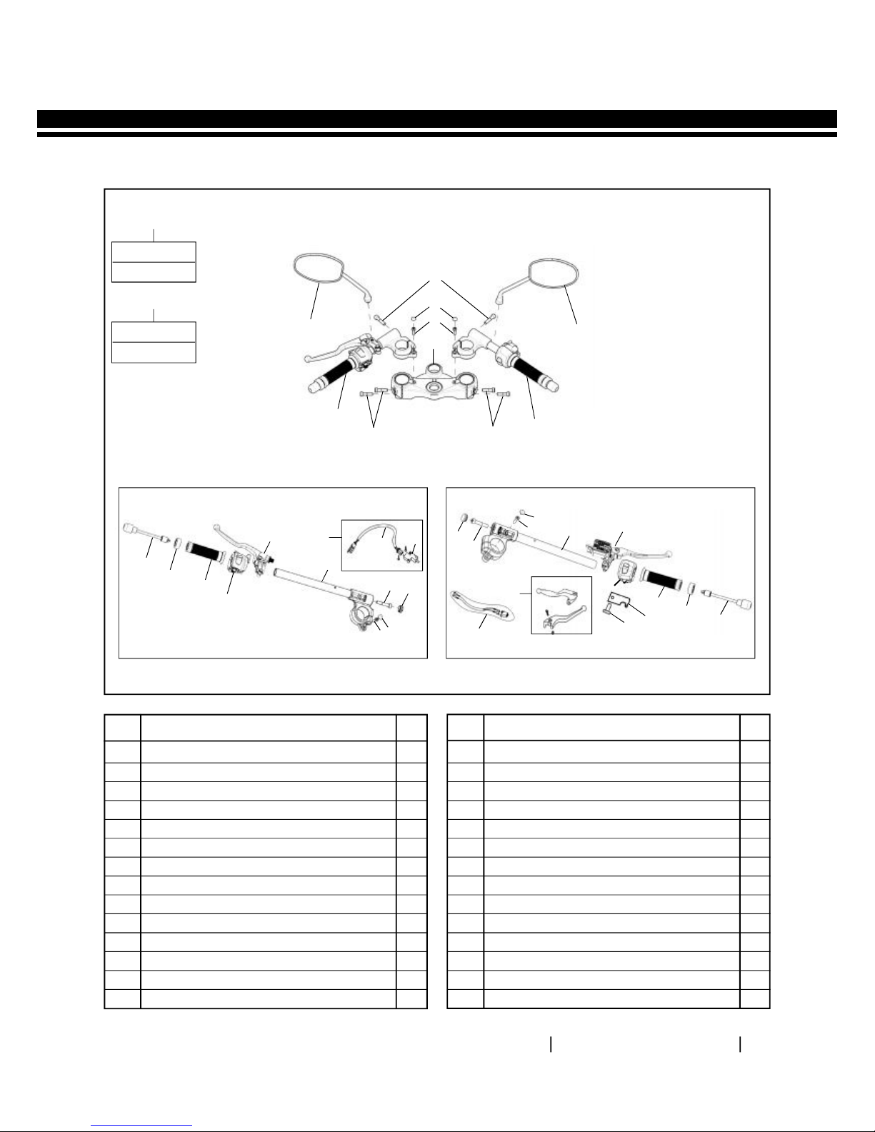
SECTION 6.3 – HANDLE BAR
7
5
10
9
12
13
14
8
2
1
3
2
1
17
18
4
ES
6
11
A1
16
15
S. NO.
DESCRIPTION
QTY. S. NO.
DESCRIPTION
QTY.
A1 Handle Bar Assembly Complete 1
1 Hex Socket Head Screw M8 X 50 2
2 Damper Weight 2
3 Hand Grip LH 1
4 Cable Strap 6" 2
Cable Strap 8" 3
5 Handle Bar Complete 1
6 Rear View Mirror LH 1
7 Rear View Mirror RH 1
8 Grip Complete - Throttle RH 1
9 Lever & Holder Assy. LH 1
10 Clutch Lever 1
11 Switch Module LH 1
12 Switch Module RH 1
13 Rotor Plate 1
14 Pan Head Screw M5 X 10 1
15 Front Brake Lever kit 1
16 Add On Lead, Front Brake Switch 1
17 Add On Lead, Clutch Switch 1
18 Clutch Switch 1
EXPLODED VIEWS
BULLET CLASSIC EFI / BULLET EFI
KS MOTORCYCLES - http://ksmotorcycles.com
ROYAL ENFIELD VEHICLE SERVICE MANUAL - EURO IV
61
CONTINENTAL GT
A1
Key Nos.
1 & 2
A2
Key Nos.
24 & 25
4
5
3
6
LH
8
3
3
2
1
7
9
10
11
12
13
14
A2
25
15
24
16
4
5
23
A3
16
15
17
4
5
18
19
20
10
9
21
22
RH
S. NO.
DESCRIPTION
QTY. S. NO.
DESCRIPTION
QTY.
A1 Mirror Set OE - Continental GT 1
A2 Clutch Switch Repair Kit 1
A3 Clutch & Front Brake Lever Kit (Clear Coated) 1
1 Rear View Mirror - LH 1
2 Rear View Mirror - RH 1
3 Hex. Socket Head Screw M8 X 35 6
4 Grommet - Clip ON 2
5 Hex. Socket Head Cap Screw M6 X 20 4
6 Top Yoke 1
7 Handle Bar Assy. - LH 1
8 Handle Bar Assy. - RH 1
9 Counter Weight Assy. 2
10 Mirror Dummy Ring 2
11 Handle Grip - LH 1
12 Switch Module - LH 1
13 Lever & Holder Assy. - LH 1
14 Handle Bar Complete - LH 1
15 Hex. Socket Head Bolt M8 X 40 2
16 Rubber Sleeve - Handle Bar 2
17 Handle Bar Complete - RH 1
18 Master Cylinder - Front 1
19 Switch Module - RH 1
20 Grip Complete - Throttle RH 1
21 Rotor Plate - Throttle Cable 1
22 Pan Head Screw M5 X 10 1
23 Add On Lead, Brake Switch 1
24 Clutch Switch 1
25 Add On Lead, Clutch Switch 1
KS MOTORCYCLES - http://ksmotorcycles.com

ROYAL ENFIELD VEHICLE SERVICE MANUAL - EURO IV
62
S.
No.
Fastener, Size, Tool Usage, Precautions, Photos
Aggregate to Dismantle /
Instructions
6.3 Handle Bar
Bullet Classic EFI /
Bullet EFI
Remove Headlamp from
the headlamp casing
and disconnect wire
terminals.
Philips head screw driver
Double end spanner
15mm
Disconnect wire couplers
from handle bar inside
the head lamp casing.
Remove Rear view
mirrors LH & RH.
Disconnect all control
cables from the handle
bar.
KS MOTORCYCLES - http://ksmotorcycles.com

ROYAL ENFIELD VEHICLE SERVICE MANUAL - EURO IV
63
S.
No.
Fastener, Size, Tool Usage, Precautions, Photos
Aggregate to Dismantle /
Instructions
6.3 Handle Bar
Bullet Classic EFI /
Bullet EFI
Remove the 2 hex bolts
on the clamp holding
Front brak e master
cylinder to handle bar.
CAUTION:
Ensure the brake lever is not
depressed while removing
from handle bar.
Hex SS Bolt : M12
Socket spanner: 14 mm
Hex bolts: M6
Socket spanner: 10 mm
Hex Nut: M8
Socket spanner: 12mm
Remove master cylinder
asse mbly from the
handle bar and support
suitably to prevent
hydraulic oil leak from
master cylinder.
Loos en and remove 2
Hex bolts along with
washers from the
handle bar clip top.
Loos en and remove 2
hex nuts along with
washers from the
handle bar clip bottom.
Remove handle bar clip
from the stu ds in the
headlamp casing and the
handle bar.
KS MOTORCYCLES - http://ksmotorcycles.com

ROYAL ENFIELD VEHICLE SERVICE MANUAL - EURO IV
64
S.
No.
Fastener, Size, Tool Usage, Precautions, Photos
Aggregate to Dismantle /
Instructions
6.3 Handle Bar
Continental GT
Remove Headlamp from
the headlamp housing
and disconnect wire
terminals.
Philips head screw driver
Double end spanner
15mm
Disconnect handle bar
LH & RH wire couplers
inside the he ad lamp
housing.
Remove Rear view
mirrors LH & RH.
Disconnect all control
cables from the handle
bar.
Remove the 2 hex bolts
on the clamp holding
Front brak e master
cylinder to handle bar.
KS MOTORCYCLES - http://ksmotorcycles.com

ROYAL ENFIELD VEHICLE SERVICE MANUAL - EURO IV
65
S.
No.
Fastener, Size, Tool Usage, Precautions, Photos
Aggregate to Dismantle /
Instructions
6.3 Handle Bar
Continental GT
Remove master cylinder
asse mbly from the
handle bar and support
suitably to prevent
hydraulic oil leak from
master cylinder.
Hex bolts: M6
Socket spanner: 10 mm
Hex. Socket Head Screw:
M8
Allen Key: 6 mm
Hex. Socket Head Screw:
M6
Allen Key: 5 mm
Loosen the hex socket
scre w clamping the
handle bar assemblies
LH & RH to the fork main
tubes.
Re move the 2 r ubber
grommets on top of the
handle bar LH & RH and
remove the 2 hex socket
head cap screws.
Remove handle bar LH &
RH form the fork main
tubes.
KS MOTORCYCLES - http://ksmotorcycles.com

ROYAL ENFIELD VEHICLE SERVICE MANUAL - EURO IV
66
S.
No.
Fastener, Size, Tool Usage, Precautions, Photos
Aggregate to Assemble /
Instructions
Locate handle bar clip on
the studs in the
headlamp casing and the
handle bar.
Install and locate 2 hex
nuts along with washers
on the handle bar clip
bottom.
Install and locate 2 Hex
bolts along with washers
on the handle bar clip
top.
Locate master cylinder
assembly on the handle
bar and support suitably
to prevent hydraulic oil
leak from ma ster
cylinder while locating.
Install the 2 hex bolts on
the clamp holding Front
brake master cylinder to
handle bar.
6.3 Handle Bar
Bullet Classic EFI /
Bullet EFI
Hex SS Bolt : M12
Socket spanner: 14 mm
Hex Nut: M8
Socket spanner: 12mm
CAUTION:
Ensure the brake lever is not
depressed while removing
from handle bar.
Hex bolts: M6
Socket spanner: 10 mm
KS MOTORCYCLES - http://ksmotorcycles.com

ROYAL ENFIELD VEHICLE SERVICE MANUAL - EURO IV
67
S.
No.
Fastener, Size, Tool Usage, Precautions, Photos
Aggregate to Assemble /
Instructions
Connect all control
cables on the handle bar.
Locate Rear view mirrors
LH & RH.
Connect wire couplers
on handle bar inside the
head lamp casing.
Locate Headlamp in the
headlamp casing an d
connect wire terminals.
6.3 Handle Bar
Bullet Classic EFI /
Bullet EFI
Double end spanner
15mm
Philips head screw driver
KS MOTORCYCLES - http://ksmotorcycles.com

ROYAL ENFIELD VEHICLE SERVICE MANUAL - EURO IV
68
S.
No.
Fastener, Size, Tool Usage, Precautions, Photos
Aggregate to Assemble /
Instructions
Locate handle bar LH &
RH on the fork main
tubes.
Loca te the 2 rubber
grommets on top of the
handle bar LH & RH and
Install the 2 hex socket
head cap screws.
In stal l the hex socket
scre w clamping the
handle bar assemblies
LH & RH to the fork main
tubes.
Locate master cylinder
assembly on the handle
bar and support suitably
to prevent hydraulic oil
leak from ma ster
cylinder.
6.3 Handle Bar
Continental GT
Hex bolts: M6
Socket spanner: 10 mm
Hex. Socket Head Screw:
M8
Allen Key: 6 mm
Hex. Socket Head Screw:
M6
Allen Key: 5 mm
KS MOTORCYCLES - http://ksmotorcycles.com

ROYAL ENFIELD VEHICLE SERVICE MANUAL - EURO IV
69
S.
No.
Fastener, Size, Tool Usage, Precautions, Photos
Aggregate to Assemble /
Instructions
Install 2 hex bolts on the
clamp holding Front
brake master cylinder to
handle bar.
Connect all control
cables from the handle
bar.
Locate Rear view mirrors
LH & RH.
Connect handle bar LH &
RH wire couplers inside
the head lamp housing.
Locate Headlamp on the
headlamp housing and
Connect wire terminals.
6.3 Handle Bar
Continental GT
Philips head screw driver
Double end spanner
15mm
KS MOTORCYCLES - http://ksmotorcycles.com

ROYAL ENFIELD VEHICLE SERVICE MANUAL - EURO IV
70
SECTION 6.4 – FRONT FORK
22
21
20
19
18
17
16
12
10
13
14
15
11
24
23
26
27
28
25
24
1
2
A1
22
21
A2
4
3
5
6
7
8
9
A1
Key Nos.
1 to 3, 5 to 20
A3
Key Nos.
Qty 2 Nos. 2, 7, 9,
11, 15 & 20
A2
Key Nos.
1, 2, 4 to 20
A4
Key Nos.
Qty 2 Nos. 2, 7, 9,
15 & 20
A5
Key Nos.
Qty. 2 Nos. 16,
20 & 22
S. NO.
DESCRIPTION
QTY. S. NO.
DESCRIPTION
QTY.
A1 Front Fork Assy - LH 1
A2 Front Fork Assy - RH 1
A3 Fork Pipe Spining Replacement Kit 1
A4 Fork Oil Seal, ‘O’-Ring & Piston Ring Kit 1
A5 Main Spring Front Fork Replacement Kit 1
1 Socket Headed Bolt 2
2 Copper Packing Washer 2
3 Outer Tube M/C - RH (Fork End) 1
4 Outer Tube M/C - LH (Fork End) 1
5 Guide Bush 2
6 Plain Washer Big 2
7 Oil Seal - LH & RH Front Fork 2
8 Oil Seal Stopper - LH & RH 2
9 Dust Seal - LH & RH 2
10 Slide Bush 1
11 Fork Pipe Spining - Inline Fork 2
12 Cap Oil Lock (Spindle Tapper) 2
13 Rebound Spring 2
14 Seat Pipe 2
15 Piston Ring - Front Fork 2
16 Main Spring 2
17 Washer - Fork Main Spring 2
18 Spacer Tube - Front Fork 2
19 Fork Bolt - Top 2
20 ‘O’ Ring - Fork Bolt Top 2
21 Plain Washer - Fork Bolt 2
22 Flange Bolt 2
23 Hex Nylock Nut M8 X 9.5 1
24 Punched Washer 2
25 Flanged Hex. Bolt M8 X 55 (Special) 1
26 Reflex Reflector (Amber) 2
27 Wheel Speed Sensor-ABS 1
28 Hex.Socket Button Head Screrw M6X1X16 1
EXPLODED VIEWS
BULLET CLASSIC EFI / BULLET EFI
KS MOTORCYCLES - http://ksmotorcycles.com

ROYAL ENFIELD VEHICLE SERVICE MANUAL - EURO IV
71
CONTINENTAL GT
25
26
24
22
A2
2
A1
3
18
15
16
17
14
13
12
4
10
20
21
1
19
11
9
8
7
6
5
23
26
25
24
A2
Key Nos.
All Except 1 & 19
A3
Key Nos.
Each Qty. 2 Nos.
3, 7, 9, 11, 17 & 20
A1
Key Nos.
All Except 2
A4
Key Nos.
QEach Qty. 2 Nos.
7, 9, 11, 17 & 20
A5
Key Nos.
(Qty. 2 Nos. 13),
16 & 17
S. NO.
DESCRIPTION
QTY. S. NO.
DESCRIPTION
QTY.
A1 Fork End LH assy 1
A2 Fork End RH assy 1
A3 Fork Pipe Spinning Replacement Kit 1
A4 Fork Oil Seal, ‘O’ Ring & Piston Ring Kit 1
A5 Main Spring Fork Major Kit 1
1 Outer Tube - RH 1
2 Outer Tube - LH 1
3 Inner Tube Assy. 2
4 Piston - Front Fork 2
5 Bush (Outer Tube) 2
6 Bush Washer 2
7 Oil Seal 2
8 Circlip (Snap - Ring) 2
9 Dust Seal 2
10 Spindle Taper 2
11 Gasket 2
12 Bolt M10X1 2
13 Spring – 1 2
14 Washer Spring Top 2
15 Spacer 2
16 Bolt Cap 2
17 ‘O’ Ring 2
18 Washer - 2 2
19 Bolt M8 X 1.25 X 45 2
20 Piston Ring 2
21 Spring - 2 2
22 Cable Guide - Brake 1
23 Cable Guide - Speedo Cable 1
24 Hex. Bolt M6 X 12 2 2
25 Plain Washer 2
26 Lock Washer, M6 2
27 Reflex Reflector Amber 2
28 Wheel Speed Sensor-ABS 2
29 Hex.Socket Button Head Screrw M6 X1 X16 1
KS MOTORCYCLES - http://ksmotorcycles.com

ROYAL ENFIELD VEHICLE SERVICE MANUAL - EURO IV
72
S.
No.
Fastener, Size, Tool Usage, Precautions, Photos
Aggregate to Dismantle /
Instructions
6.4 Front Fork LH & RH
Bullet EFI / Bullet
Classic EFI
Remove Front wheel as
described in F ron t
Wheel section 6.1.
Remove front mud-
guard as deta iled in
Section 6.2.
Ensure wheel speed
sensor is removed from
the fork end LH.
Discon nect Trafficator
couplers LH & RH inside
headlamp casing.
Loosen Hex Nylock nuts
on steering stem pinch
bolt L H & RH remove
trafficator assembly
with bracket on LH & RH
side.
Hold the pinch bolts LH
& RH and loosen hex nut
Loosen nut by holding
fork pinch bolt in bottom
yoke (steering stem) on
RH & LH side.
Hex Nylock Nut: M8
Ring spanner: 12mm
Hex bolt M8
Hex Nylock Nut: M8
Double end spanner:
12mm
Ring spanner: 12mm
KS MOTORCYCLES - http://ksmotorcycles.com

ROYAL ENFIELD VEHICLE SERVICE MANUAL - EURO IV
73
S.
No.
Fastener, Size, Tool Usage, Precautions, Photos
Aggregate to Dismantle /
Instructions
6.4 Front Fork LH & RH
Bullet EFI / Bullet
Classic EFI
Loos en and remove 2
Hex socket screws from
the top of the front forks
on the head lamp casing.
Gently rotate and
remove the fork
assembly LH & RH from
the head lamp c asin g
and the steering stem.
Hex Hd Cap screw M10
Allen Key 8 mm
KS MOTORCYCLES - http://ksmotorcycles.com

ROYAL ENFIELD VEHICLE SERVICE MANUAL - EURO IV
74
S.
No.
Fastener, Size, Tool Usage, Precautions, Photos
Aggregate to Dismantle /
Instructions
6.4 Front Fork LH & RH
Continental GT
Hex bolt M8
T spanner 12 mm
Hex. Socket Screw M8
Allen key 6 mm
Remove Front wheel as
described in F ron t
Wheel section 6.1.
Remove front mud-
guard as detailed above
in Section 6.2.
Ensure front brake
caliper is disma ntle d
from the fork LH.
Ensure wheel speed
sensor is removed from
the fork end LH.
Remove Headlamp from
the headlamp housing
and disc onne ct all
elec trical connections
inside headlamp housing.
Loosen and remove the
2 hex bolts holding head
lamp housing to the
holder RH & LH.
Loosen the 2 hex socket
screws inside the head
lamp holder R H & LH.
Ensure the head lamp
holders are free on the
front fork main tube.
KS MOTORCYCLES - http://ksmotorcycles.com

ROYAL ENFIELD VEHICLE SERVICE MANUAL - EURO IV
75
S.
No.
Fastener, Size, Tool Usage, Precautions, Photos
Aggregate to Dismantle /
Instructions
6.4 Front Fork LH & RH
Continental GT
Loosen the 4 hex socket
head cap bolts (2 each
on LH & RH sides) from
the steering stem.
Loosen the 4 hex socket
head cap bolts (2 each
on LH & RH sides) from
the top yoke.
Gently rotate and
remove the forks LH &
RH f rom the s teering
stem and top yoke.
NOTE:
Support the head la mp
holders with the trafficators
while removing the forks LH
& RH from the steering stem.
Hex Screw M6
Allen key 5 mm
KS MOTORCYCLES - http://ksmotorcycles.com

ROYAL ENFIELD VEHICLE SERVICE MANUAL - EURO IV
76
S.
No.
Fastener, Size, Tool Usage, Precautions, Photos
Aggregate to Assemble /
Instructions
6.4 Front Fork LH & RH
Bullet EFI / Bullet
Classic EFI
Gently rotate and locate
the fork assembly LH &
RH on the head lamp
casing and the steering
stem.
Install and locate 2 Hex
socket screws in the top
of the front forks on the
head lamp casing.
Hex Screw M10
Allen Key 8 mm
Hex Nylock Nut: M8
Ring spanner: 12mm
Hex bolt M8
Hex Nylock Nut: M8
Double end spanner:
12mm
Ring spanner: 12mm
Hold the pinch bolts LH
& RH and Install hex nut
Loosen nut by holding
fork pinch bolt in bottom
yoke (steering stem) on
RH & LH side.
Install Hex Nylock nuts
on steering stem pinch
bolt LH & RH and locate
trafficator assembly with
bracket on LH & RH side.
Connect Tra fficator
couplers LH & RH inside
headlamp casing.
KS MOTORCYCLES - http://ksmotorcycles.com

ROYAL ENFIELD VEHICLE SERVICE MANUAL - EURO IV
77
S.
No.
Fastener, Size, Tool Usage, Precautions, Photos
Aggregate to Assemble /
Instructions
6.4 Front Fork LH & RH
Bullet EFI / Bullet
Classic EFI
Ensure wheel speed
sensor is located in the
fork end LH.
Locate front mudguard
as detailed above.
Assemble Front whe el
as described in Fron t
Wheel section 6.1.
KS MOTORCYCLES - http://ksmotorcycles.com

ROYAL ENFIELD VEHICLE SERVICE MANUAL - EURO IV
78
S.
No.
Fastener, Size, Tool Usage, Precautions, Photos
Aggregate to Assemble /
Instructions
6.4 Front Fork LH & RH
Continental GT
Locate the fork assem-
bly LH & RH on the head
lamp casing and t he
steering stem.
Gently rotate and locate
the forks LH & RH on the
steering stem and top
yoke.
Install the 4 hex socket
head cap bolts (2 each
on LH & RH sides) on the
top yoke.
NOTE:
Support the head la mp
holders with the trafficators
while removing the forks LH
& RH from the steering stem.
Hex Socket Screw M6
Allen key 5 mm
Hex Socket Screw M8
Allen key 6 mm
Install the 4 hex socket
head cap bolts (2 each
on LH & RH sides) on the
steering stem.
Install the 2 hex socket
screws inside the head
lamp holder R H & LH.
Ensure the head lamp
holders are fixed on the
front fork main tube.
Install and locate the 2
hex bolts holding head
lamp housing to the
holder RH & LH.
Locate Headlamp in the
headlamp housing and
connect a ll electr ical
connections inside
headlamp housing.
KS MOTORCYCLES - http://ksmotorcycles.com

ROYAL ENFIELD VEHICLE SERVICE MANUAL - EURO IV
79
S.
No.
Fastener, Size, Tool Usage, Precautions, Photos
Aggregate to Assemble /
Instructions
6.4 Front Fork LH & RH
Continental GT
Ensure wheel speed
sensor is located in the
fork end LH.
Ensure front brake
caliper is located in the
fork LH.
Locate front mudguard
as detailed above.
Assemble Front whe el
as described in Fron t
Wheel section 6.1.
Hex bolt M8
T spanner 12 mm
KS MOTORCYCLES - http://ksmotorcycles.com

ROYAL ENFIELD VEHICLE SERVICE MANUAL - EURO IV
80
S.
No.
Fastener, Size, Tool Usage, Precautions, Photos
Aggregate to Dismantle /
Instructions
6.4 Front Fork Oil
Draining
Hold the fork assembly
in bench vice with soft
jaws, approx imately 6
inches from the top and
loosen top nut.
Remove fork assembly
from the bench vise.
Hold upright and gently
remove fork top nut with
washer, allowing spring
to expand slowly.
Hex nut M16
Double end spanner
24 mm
Remove washer, spacer
and washer spring top
from the inner tube.
NOTE:
Replace all Rubber parts, ,
plastic bushe s, O rings,
washers whenever they are
removed.
Re move long spring
from inner tube.
KS MOTORCYCLES - http://ksmotorcycles.com

ROYAL ENFIELD VEHICLE SERVICE MANUAL - EURO IV
81
S.
No.
Fastener, Size, Tool Usage, Precautions, Photos
Aggregate to Dismantle/
Instructions
6.4 Front Fork Oil
Draining
Invert the fork assembly
to drain out the oil from
the fork.
Gently pump main tube
into the bottom tube to
drain out the oil
completely.
Repeat the above process
to drain oil from t he
other fork assembly.
KS MOTORCYCLES - http://ksmotorcycles.com

ROYAL ENFIELD VEHICLE SERVICE MANUAL - EURO IV
82
S.
No.
Fastener, Size, Tool Usage, Precautions, Photos
Aggregate to Assemble /
Instructions
6.4 Front Fork Oil
Filling
Fill Fork oil 195 ml/leg
(For Bullet & Classic
Models) and 430 ml/leg
(For Con ti-GT Model)
with 2W 35 Grade.
Locate long spring into
the inner tube.
NOTE:
Replace all Rubber parts, ,
plastic bushe s, O rings,
washers whenever they are
removed.
Locate washer, space r
and washer spring top in
the inner tube.
KS MOTORCYCLES - http://ksmotorcycles.com

ROYAL ENFIELD VEHICLE SERVICE MANUAL - EURO IV
83
S.
No.
Fastener, Size, Tool Usage, Precautions, Photos
Aggregate to Assemble /
Instructions
6.4 Front Fork Oil
Filling
Locate fork top nut with
washer, allowing spring
to compress slowly.
Repeat the above
process to fill oil and
assemble the other fork
assembly.
Hex nut M16
Double end spanner
24 mm
KS MOTORCYCLES - http://ksmotorcycles.com

ROYAL ENFIELD VEHICLE SERVICE MANUAL - EURO IV
84
S.
No.
Fastener, Size, Tool Usage, Precautions, Photos
Aggregate to Assemble/
Instructions
6.4 Front Fork
Assembling
Remove the pinch bolt
and nut on Fork RH.
Loca te s pecial tool
inside inner tube such
that it engages with the
nut on th e seat pipe
inside.
Loosen and remove the
hex socket head nut
inside the outer tube.
Hex bolt & nut: M6
Ring spanners: 10mm
Special Tool: ST-25834-2
Allen Key: 10mm
Remove the special tool
from the inner tube.
Remove the dust seal,
reta iner clip, and fork
seal from the outer tube.
Pull out the inner tube
from the outer tube
sharply to remove the
inner tube along with the
guide bush, sea t pipe
asse mbly, rebound
spring and cap oil lock.
KS MOTORCYCLES - http://ksmotorcycles.com

ROYAL ENFIELD VEHICLE SERVICE MANUAL - EURO IV
85
S.
No.
Fastener, Size, Tool Usage, Precautions, Photos
Aggregate to Dismantle/
Instructions
6.4 Front Fork
Dismantling
Pull in the inner tube on
the outer tube sharply
to locate the inner tube
along with the guide
bush, seat pipe assembly,
rebound spring and cap
oil lock.
Loca te the dust s eal,
reta iner clip, and fork
seal in the outer tube.
Locate the special tool in
the inner tube.
Loca te and in stal l the
hex socket head nut
inside the outer tube.
Loca te s pecial tool
inside inner tube such
that it engages with the
nut on the seat pipe inside.
Loca te the pinch bolt
and nut on Fork RH.
Special Tool: ST-25834-2
Allen Key: 10mm
Hex bolt & nut: M6
Ring spanners: 10mm
KS MOTORCYCLES - http://ksmotorcycles.com

ROYAL ENFIELD VEHICLE SERVICE MANUAL - EURO IV
86
INSPECTION
Inspect front fork inner tube for any damages and bends.
Inspect front fork outer tube for any damages, cracks at oil seal seating area.
WEAR LIMIT
Main tube straightness
Fork spring long
Long Pitch
Short Pitch
Spring Length ------ mm
Fork spring short
Service Limit: 0.15 mm
Guide Bush
Length
New Spring: --------mm
Service Limit: -------mm
KS MOTORCYCLES - http://ksmotorcycles.com

ROYAL ENFIELD VEHICLE SERVICE MANUAL - EURO IV
87
8
7
8
7
9
6
9
1
2
4
1
4
5
3
3
22
23
24
22
24
23
26
27
25
20
19
18
28
14
15
16
14
15
16
12
10
11
13
12
17
21
SECTION 6.5 – STEERING STEM
S. NO.
DESCRIPTION
QTY. S. NO.
DESCRIPTION
QTY.
1 Cover 2
2 Ball Race, Head Lamp Casing 1
3 Steering Stem Ball Cage 2
4 Ball Race, Frame 2
5 Ball Race, Fork Crown 1
6 Steering Stem Assy. 1
7 Flanged Hex Nut M8 x 7.7 X 8 2
8 Hex Nut with Nylock insert - M8 X 9.5 2
9 Flange Bolt (M8 × 75) 2
10 Stem Lock Nut 1
11 Steering Stem Lock Nut Washer 1
12 Washer 2
13 Hex SS Bolt M8 x 48 2
14 Stud (M8×32) 2
15 Washer 2
16 Nut 2
17 Clip, Handle Bar 1
18 Sleeve, Threaded 1
19 Sleeve, Plain 1
20 Hex Socket head Cap Screw M10 x 1.5 x 35 1
21 Adaptor AHO 1
22 Rubber Spacer 2
23 Bush 2
24 Cover Tube 2
25 Head Lamp Casing 1
26 Rr Cover Comp C5 1
27 Slotted Rd. Hd.Screw 2
28 Rubber Grommet 2
EXPLODED VIEWS
BULLET CLASSIC EFI / BULLET EFI
KS MOTORCYCLES - http://ksmotorcycles.com

ROYAL ENFIELD VEHICLE SERVICE MANUAL - EURO IV
88
CONTINENTAL GT
1
6
7
10
11
12
3
3
9
8
8
5
4
7
3
3
2
S. NO.
DESCRIPTION
QTY. S. NO.
DESCRIPTION
QTY.
1 Lock Nut 1
2 Top Yoke 1
3 Hex. Socket Head Bolt M8 X 35 8
4 Ring Nut 2
5 Dust Cap - Top Yoke 1
6 Ball Race - Top Yoke 1
7 Steering stem - Ball Cage 2
8 Ball Race - Frame Head Tube 2
9 Dust Cap - Frame 1
10 Steering Stem Assembly 1
11 Ball Race - Bottom Yoke 1
12 Dust Seal - Bottom Yoke 1
KS MOTORCYCLES - http://ksmotorcycles.com

ROYAL ENFIELD VEHICLE SERVICE MANUAL - EURO IV
89
S.
No.
Fastener, Size, Tool Usage, Precautions, Photos
Aggregate to Assemble /
Instructions
6.5 Steering Play
Adjustment
Bullet Classic EFI /
Bullet EFI
Rock the front end and
feel the play at stem top
end.
NOTE:
Every 6,000 KMS, Steering
Ball race adjustment should
be done and on Ever y
12,00 0 Km Lubrication is
recommended.
Lock Nut M20
Socket Spanner - 30 mm
Dome Lock Nut M24
Socket Spanner – 30 mm
Torque – 50 Nm
Finally tighten all the
nuts and bolts in reverse
order.
If felt, adjust as follows:
Loosen steering bottom
bridge pinch bolt and
nuts of Right & Left side.
Loosen the stem lock nut
and then tight steering
stem tapper n ut t o
adjust excess play.
Again re-check play, it
should be free without
any play.
KS MOTORCYCLES - http://ksmotorcycles.com

ROYAL ENFIELD VEHICLE SERVICE MANUAL - EURO IV
90
S.
No.
6.5 Steering Play
Adjustment
Continental GT
Fastener, Size, Tool Usage, Precautions, Photos
Aggregate to Assemble /
Instructions
Place Motorcycle on
Center Stand.
Ke ep a wooden plank
under the stand to Rise
the Front Wheel.
CAUTION:
Do not Use Sockets
Directly.
Hex Socket Screw M5
Allen Key 6mm
Steering
Dome Nut
X
Don’t
CAUTION:
Do n ot Use Sockets
Directly.
Dome Lock Nut M24
Socket Spanner – 30 mm
If felt, adjust as follows :
Loos en the steeri ng
dome nut with long
extension rod.
Loosen the pinch bolts in
bottom yoke on LH and
then RH side.
Hold the Fork pipe (Main
Tube ) pull and push
simultaneously lift the
front whe el upw ards
and check for Steering
play.
Rock th e fr ont wheel
down wards and feel the
play / sound at stem top
dome nut by fingers.
KS MOTORCYCLES - http://ksmotorcycles.com

ROYAL ENFIELD VEHICLE SERVICE MANUAL - EURO IV
91
S.
No.
Fastener, Size, Tool Usage, Precautions, Photos
Aggregate to Assemble /
Instructions
6.5 Steering Play
Adjustment
Continental GT
C Spanner
CAUTION:
Do not use Ring spanner
directly to tig hten dome
nut.
Dome Lock Nut M24
Socket Spanner – 30 mm
Torque – 50 Nm
Loosen the lock ring nut
before a djusting
Steering play.
Again check and confirm
the steering free play.
After adjusting the play
then tighten Dome nut
to Torque.
After adjusting the play
then tighten loc k nut
against ring nut.
In case of excessive
steering play tighten the
stee ring ring nut by
using spe cial tool (C
spanner).
KS MOTORCYCLES - http://ksmotorcycles.com

ROYAL ENFIELD VEHICLE SERVICE MANUAL - EURO IV
92
S.
No.
Fastener, Size, Tool Usage, Precautions, Photos
Aggregate to Assemble /
Instructions
6.5 Steering Play
Adjustment
Continental GT
Hex Socket Screw M5
Allen Key 6mm
Torque 25 NM
NOTE:
Take a small test ride to
ensure that
- Steering free movement.
- No dragging.
- No sound from steering
stem / mounting area.
Now check the handle
bar free movement by
turning extreme Left to
Right side.
Tighten the pinch bolts
in bottom yoke LH and
then RH by using Allen
key.
KS MOTORCYCLES - http://ksmotorcycles.com

ROYAL ENFIELD VEHICLE SERVICE MANUAL - EURO IV
93
S.
No.
Fastener, Size, Tool Usage, Precautions, Photos
Aggregate to Dismantle /
Instructions
6.5 Headlamp Casing &
Steering Stem
Bullet Classic EFI /
Bullet EFI
Disconnect speedometer
ca ble fr om t he
spee dometer.
Disconn ect wiring
couplers of the speedomete r, MIL meter,
ignition switch a nd
parking lamps from the
main wiring harness.
Re move the clu tch,
thrott le and bi-starter
cables from the hole in
the headlamp casing.
Loos en & remove the
hex Nylock nut and bolt
holding RR cover and
cover tube to th e
steering stem.
Hex Soc Hd Cap screw:
M10
Allen key 12 mm
Loosen and remove the
steering stem lock nut
from the headlamp
casi ng along with the
washer.
Remove the fork cover
tubes LH & RH along with
the rubber spacers and
plastic bushes.
Loos en soc ket head
screw in the head lamp
casing inner side by 3 to
4 threads.
Support t he ste ering
stem at the bottom.
Hex nut (Steering stem
lock nut) : M24
Ring spanner: 30mm
KS MOTORCYCLES - http://ksmotorcycles.com

ROYAL ENFIELD VEHICLE SERVICE MANUAL - EURO IV
94
S.
No.
Fastener, Size, Tool Usage, Precautions, Photos
Aggregate to Dismantle/
Instructions
6.5 Headlamp Casing &
Steering Stem
Bullet Classic EFI /
Bullet EFI
Gently lower the
stee ring ste m and
remove from the frame.
Remove the Headlamp
casing from the frame.
Using a long chisel, gently
tap and drive out the top
and bottom races from
the frame h ead tube
along with the dust cap.
Re move the top and
bottom ball cage from
the ball races.
Using a short chisel, drive
out the ball race along
with dust cap from the
headlamp casing and the
ball race from steering
stem.
KS MOTORCYCLES - http://ksmotorcycles.com

ROYAL ENFIELD VEHICLE SERVICE MANUAL - EURO IV
95
S.
No.
Fastener, Size, Tool Usage, Precautions, Photos
Aggregate to Assemble /
Instructions
6.5 Headlamp Casing &
Steering Stem
Bullet Classic EFI /
Bullet EFI
Using a short chisel, drive
in the ball race along with
dust cap on th e
headlamp casing and the
ball race in steering
stem.
Loosen and remove the
steering stem lock nut
from the headlamp
casi ng along with the
washer.
Remove the fork cover
tubes LH & RH along with
the rubber spacers and
plastic bushes.
Loca te stee ring stem
and assemble on the
frame.
Using a long chisel, gently
tap and drive in at the
top and bottom races on
the frame h ead tube
along with the dust cap.
Loca te the top and
bottom ball cage from
the ball races.
Loca te the Headlamp
casing in the frame.
KS MOTORCYCLES - http://ksmotorcycles.com

ROYAL ENFIELD VEHICLE SERVICE MANUAL - EURO IV
96
S.
No.
Fastener, Size, Tool Usage, Precautions, Photos
Aggregate to Assemble /
Instructions
6.5 Headlamp Casing &
Steering Stem
Bullet Classic EFI /
Bullet EFI
Loca te the fork cover
tubes LH & RH along with
the rubber spacers and
plastic bushes.
Loca te and in stal l the
steering stem lock nut in
the headlamp casing
along with the washer.
In stal l socket head
screw in the head lamp
casing inner side by 3 to
4 threads.
Locate & Install the hex
Nylock nut and bolt
holding RR cover and
cover tube to th e
steering stem.
Loca te the fork cover
tubes LH & RH along with
the rubber spacers and
plastic bushes.
Loca te and in stal l the
steering stem lock nut in
the headlamp casing
along with the washer.
Hex Soc Hd Cap screw:
M10
Allen key 12 mm
Loca te the clutch,
thrott le and bi-starter
cables on the hole in the
headlamp casing.
Connect wiring couplers
of the speedometer, MIL
meter, ignition switch,
and parking lamps in the
main wiring harness.
Connect speedom eter
cable from the speedometer.
Hex nut (Steering stem
lock nut) : M24
Ring spanner: 30mm
Torque: 70 Nm
KS MOTORCYCLES - http://ksmotorcycles.com

ROYAL ENFIELD VEHICLE SERVICE MANUAL - EURO IV
97
S.
No.
Fastener, Size, Tool Usage, Precautions, Photos
Aggregate to Dismantle /
Instructions
6.5 Top Yoke & Steering
Stem
Continental GT
Disconn ect a ll wirin g
couple rs of th e
inst rument cluster to
main wiring harness.
Re move speed se nsor
wire coupler from wiring
harness.
Remove the top lock nut
on the top yoke.
Re move the top yoke
along with th e
instrument cluster and
ignition switch.
Support steering stem
and th e bottom and
loosen and remove the
top ring nut first and the
second ring nut next.
KS MOTORCYCLES - http://ksmotorcycles.com

ROYAL ENFIELD VEHICLE SERVICE MANUAL - EURO IV
98
S.
No.
Fastener, Size, Tool Usage, Precautions, Photos
Aggregate to Dismantle/
Instructions
6.5 Top Yoke & Steering
Stem
Continental GT
Gently lower the
stee ring ste m and
remove from the frame.
Re move the top and
bottom ball cage from
the ball races.
Using a long chisel, gently
tap and drive out the top
and bottom races from
the frame h ead tube
along with the dust cap.
Using a short chisel, drive
out the ball race along
with dust cap from the
top y oke and the ball
race from steering stem.
KS MOTORCYCLES - http://ksmotorcycles.com

ROYAL ENFIELD VEHICLE SERVICE MANUAL - EURO IV
99
S.
No.
Fastener, Size, Tool Usage, Precautions, Photos
Aggregate to Assemble /
Instructions
6.5 Top Yoke & Steering
Stem
Continental GT
Using a short chisel, drive
in the ball race along with
dust cap in the top yoke
and the ball race on
steering stem.
Using a long chisel, gently
tap and drive in at the
top a nd bottom ra ces
from the frame head
tube along with the dust
cap.
Loca te the top and
bottom ball cage in the
ball races.
Loca te stee ring stem
and assemble on the
frame.
NOTE:
Replace all Rubber parts, ,
plastic bushe s, O rings,
washers whenever they are
removed.
KS MOTORCYCLES - http://ksmotorcycles.com
 Loading...