

Page 1
CLAUDIA - IVANA - ANTONELLA - KLIMA12
ISTRUZIONI USO E MANUTENZIONE
INSTRUCTIONS FOR USE AND MAINTENANCE
GEBRAUCHS- UND WARTUNGSANLEITUNG
La stufa a combustione ecologica che riscalda la tua casa
The eco-friendly combustion stove that heats your home
Der Heizofen mit der umweltfreundlichen Verbrennung, der Ihr ganzes Haus heizt
Page 2
Le apparecchiature da riscaldamento (denominate
in seguito “stufe”) Royal (di seguito ROYAL) sono
costruite e collaudate seguendo le prescrizioni di
sicurezza indicate nelle direttive europee di
riferimento.
Questo manuale è indirizzato ai proprietari, agli
installatori, operatori e manutentori delle stufe.
In caso di dubbi sul contenuto e per ogni chiarimento
contattare il costruttore o il servizio di assistenza
tecnica autorizzato citando il numero del paragrafo
dell'argomento in discussione.
La stampa, la traduzione e la riproduzione anche
parziale del presente manuale s'intendono vincolata
dall'autorizzazione Royal.
Le informazioni tecniche, le rappresentazioni grafiche
e le specifiche presenti in questo manuale non sono
divulgabili.
IT
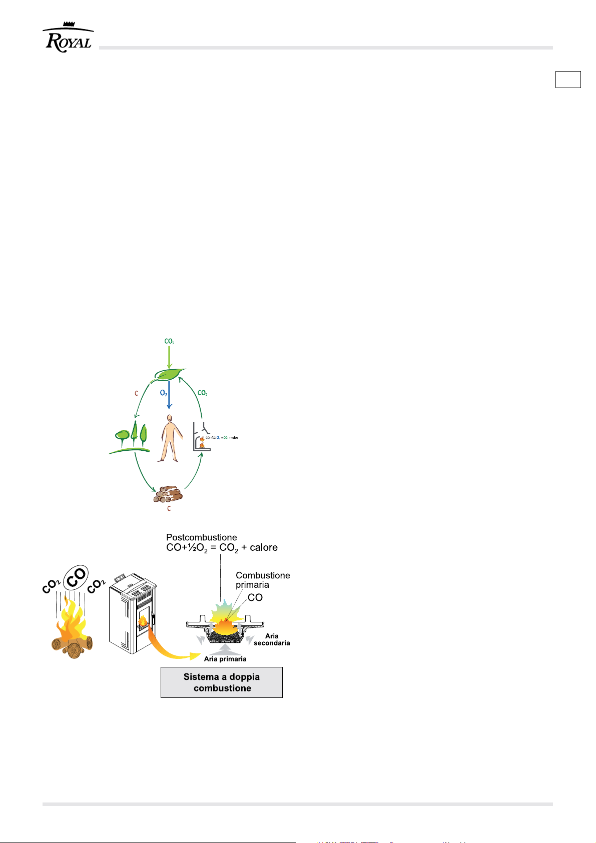
IL SISTEMA A DOPPIA COMBUSTIONE
La fiamma prodotta dalla legna che brucia correttamente in
una stufa emette la stessa quantità di anidride carbonica (CO
che si sarebbe liberata in seguito alla naturale
decomposizione del legno stesso.
La quantità di CO
decomposizione di una pianta corrisponde alla quantità di
CO
che la pianta stessa è in grado di prelevare dall’ambiente
2
e trasformare in ossigeno per l’aria e carbonio per la pianta,
nel corso del suo ciclo di vita.
L’uso di combustibili fossili non rinnovabili (carbone, gasolio,
gas), a differenza di quanto avviene con la legna, libera nell’aria
enormi quantità di CO
aumentando la formazione dell’effetto serra. L’uso della legna
come combustibile, quindi, è in perfetto equilibrio con
l’ambiente in quanto viene utilizzato un combustibile rinnovabile
ed in armonia con il ciclo ecologico della natura.
Il principio della combustione pulita risponde in pieno a questi
obiettivi e la Royal vi ha fatto riferimento nella progettazione
dei propri prodotti.
Cosa intendiamo per combustione pulita e come avviene? Il
controllo e la regolazione di aria primaria e l’immissione
dell’aria secondaria provoca una seconda combustione, o
post-combustione caratterizzata da una seconda fiamma più
viva e più limpida che si sviluppa al di sopra della fiamma
principale. Essa, grazie all’immissione di nuovo ossigeno,
brucia i gas incombusti migliorando sensibilmente il
rendimento termico e riducendo al minimo le emissioni nocive
di CO (monossido di carbonio) dovute alla combustione
incompleta. È questa una caratteristica esclusiva delle stufe e
di altri prodotti ROYAL.
prodotta dalla combustione o
2
accumulate nel corso di milioni di anni,
2
)
2
cod. 004771021 - Claudia - Ivana - Antonella - Klima 122
Page 3

Royal's series of heating appliances are made and
GB D
tested following the safety rules and regulations as
laid down in the relative European directives.
This manual is for owners, installers, operators and
maintenance engineers of the series of stoves.
If you have any doubts about the contents or need
some clarifications, do not hesitate to contact the
manufacturer or an authorised technical assistance
centre, giving the number of the paragraph in
question.
The printing, translation and reproduction, even partial,
of this manual are bound by Royal's authorisation.
Die Heizgeräte (anstehend „Heizofen“ genannt) der
ROYAL (in Folge ROYAL) Serie werden unter
Einhaltung der von den diesbezüglichen europäische
Richtlinien vorgegebenen Sicherheitsbestimmungen
hergestellt und geprüft.
Dieses Handbuch richtet sich an den Eigentümer des
Heizofens Mod. , sowie an die Installateure, Bediener
und das Wartungspersonal.
Im Zweifelsfalle bzw. für jede weitere Erklärung zum
Handbuch ist mit dem Hersteller oder der befugten
Kundendienststelle Kontakt aufzunehmen. Dabei
bitte die Absatznummer und das betroffene Thema
angeben.
The technical information, graphs and specifications
in this manual are not to be disclosed.
Der Druck, die Übersetzung und auch nur die
teilweise Vervielfältigung dieses Handbuchs
unterstehen der Genehmigung seitens der Fa. Royal.
Die in diesem Handbuch enthaltenen technischen
Informationen, grafischen Darstellungen und
Spezifikationen dürfen nicht verbreitet werden.
DAS SYSTEM DER DOPPELTEN
VERBRENNUNG
DUAL COMBUSTION SYSTEM
In a wood burning stove, a correctly burning flame emits the
same amount of carbon dioxide (CO
through the natural decomposition of the same wood.
The quantity of CO
of a tree corresponds to the quantity of CO
capable of extracting from the environment and transforming
into oxygen for the air and carbon for itself during its lifetime.
Unlike wood, when fossil fuels are burned - which are not
renewable, like coal, diesel oil, gas - a huge amount of C0
accumulated in the course of millions of years is emitted into
the atmosphere, increasing the green-house effect.
Consequently, the use of wood as fuel maintains the perfect
equilibrium of nature because it is a renewable fuel whose
burning is compatible with nature's life cycle.
The principle of clean combustion is in perfect harmony with
these characteristics and Royal always refers to it when
designing its products.
What exactly do we mean by clean combustion and how does
it come about? By controlling the flow of primary air and by
adding secondary air, a second level of combustion, or postcombustion, takes place. This is indicated by a second
characteristically clearer and stronger flame above the main
flame. By adding new oxygen, this flame consumes the
unburned gasses, greatly improving heat production and
reducing the harmful emission of CO (carbon monoxide)
caused by incomplete combustion. This is a unique feature of
the stoves and other ROYAL products.
produced by combustion or decomposition
2
) as would be emitted
2
that the tree itself is
2
Eine in einem Heizofen korrekt brennende Flamme gibt die
gleiche Menge an Kohlendioxyd (CO
natürliche Zersetzung des Holzes selbst hätte erzeugt werden
können.
Die von der Verbrennung oder Zersetzung einer Pflanze
erzeugte CO
Pflanze während ihres Lebenszyklus aus der Atmosphäre
entnimmt und für die Luft in Sauerstoff bzw. für die Pflanze in
Kohlenstoff umwandeln kann.
Bei der Verwendung von nicht erneuerbaren Fossilbrennstoffen
(Kohle, Dieselöl, Gas) werden im Gegenteil zum Holz enorme
Mengen an CO
2
angesammelt hat, an die Atmosphäre abgegeben, was zur
Erhöhung des “Treibhauseffekts” beiträgt. Demnach kann die
Anwendung von Holz als Brennstoff als umweltfreundlich
angesehen werden, da ein erneuerbarer Brennstoff verwendet
wird, der sich harmonisch in den natürlichen, ökologischen
Zyklus einfügt.
Das von Royal für Heizöfen und Kamine angewandte Prinzip
der sauberen Verbrennung entspricht voll und ganz diesen
Zielsetzungen, wonach man sich auch in der Planung der
Produkte hält.
Was versteht man unter sauberer Verbrennung und wie
funktioniert sie? Die Kontrolle der Primärluft und die Zufuhr von
Sekundärluft bewirken eine zweite Verbrennung bzw. eine so
genannte Nachverbrennung, bei der sich eine zweite Flamme
über der ersten entwickelt und lebendiger und auch klarer brennt.
Sie verbrennt durch die Zufuhr der Sekundärluft die
unverbrannten Gase, wodurch die Heizleistung wesentlich
verbessert wird: die schädlichen, durch die unvollständige
Verbrennung bedingten CO-Emissionen (Kohlenmonoxyd)
werden auf ein Minimum reduziert. Es handelt sich hierbei um
ein exklusives Merkmal der Öfen und anderen Produkte der
Fa. ROYAL.
-Menge entspricht der Menge, die eben diese
2
, das sich im Laufe von Millionen Jahren
2
) ab, die durch die
2
3cod. 004771021 - Claudia - Ivana - Antonella - Klima 12
Page 4
INDICE
1 PREMESSA
1.1 SIMBOLOGIA
1.2 DESTINAZIONE D’USO
1.3 SCOPO E CONTENUTO DEL MANUALE
1.4 CONSERVAZIONE DEL MANUALE
1.5 AGGIORNAMENTO DEL MANUALE
1.6 GENERALITÀ
1.7 PRINCIPALI NORME ANTIFORTUNISTICHE
RISPETTATE E DA RISPETTARE
1.8 GARANZIA LEGALE
1.9 RESPONSABILITÀ DEL COSTRUTTORE
1.10 CARATTERISTICHE DELL’UTILIZZATORE
1.11 ASSISTENZA TECNICA
1.12 PARTI DI RICAMBIO
1.13 TARGHETTA DI IDENTIFICAZIONE
1.14 CONSEGNA DELLA STUFA
2 AVVERTENZE PER LA SICUREZZA
2.1 AVVERTENZE PER L’INSTALLATORE
2.2 AVVERTENZE PER L’UTILIZZATORE
2.3 AVVERTENZE PER IL MANUTENTORE
3 CARATTERISTICHE DEL COMBUSTIBILE E
DESCRIZIONE DELLA STUFA
3.1 CARATTERISTICHE DEL COMBUSTIBILE
3.2 STOCCAGGIO DEL PELLET
3.3 DESCRIZIONE DELLE PARTI PRINCIPALI DELLA
STUFA
4 MOVIMENTAZIONE E TRASPORTO
5 PREPARAZIONE DEL LUOGO
DI INSTALLAZIONE
5.1 PRECAUZIONI PER LA SICUREZZA
5.2 CONSIDERAZIONI GENERALI
5.3 LUOGO DI INSTALLAZIONE DELLA STUFA
5.4 ARIA COMBURENTE
5.5 SCARICO FUMI
5.5.1 Scarico a tetto mediante canna fumaria
6 INSTALLAZIONE
6.1 LIVELLAMENTO DELLA STUFA
6.2 ALLACCIAMENTO AGLI IMPIANTI
6.2.1 Collegamento elettrico
6.2.1.1 Messa a terra
6.2.1.2 Avviamento
7 MESSA IN SERVIZIO ED USO DELLA STUFA
7.1 CARICAMENTO PELLET
7.2 DESCRIZIONE PANNELLO COMANDI
7.3 FASE DI AVVIO DELLA COMBUSTIONE
7.3.1 Alimentazione elettrica
7.3.2 Fase di AVVIO (accensione stufa)
7.4 FASE DI LAVORO
7.5 FASE DI SPEGNIMENTO DELLA STUFA
7.6 USO AVANZATO DEL PANNELLO COMANDO
7.6.1 Orologio
7.6.2 Cronotermostato
7.7 GESTIONE ALLARMI
7.7.1 Allarme ALAr ACC (allarme accensione)
7.7.2 Allarme CooL FirE (allarme interruzione tensione
di rete)
7.7.3 Allarme ALar Sond (allarme sonda fumi)
7.7.4 Allarme ALar dEP (allarme depressione)
7.7.5 Allarme ALar PELL (allarme temperatura pellet)
7.7.6 Allarme ALar FAn (allarme ventilatore aspirazione)
7.7.7 Allarme ALar hot (allarme sovra temperatura fumi)
7.7.8 Allarme ALar FirE (allarme spegnimento durante
la fase di lavoro)
7.7.9 Allarme ALar Sic (allarme termostato generale)
7.8 PULIZIA BRACIERE
8 MANUTENZIONE E PULIZIA
8.1 PRECAUZIONI DI SICUREZZA
8.2 MANUTENZIONE ORDINARIA RIVOLTA
ALL’UTILIZZATORE
8.2.1 Pulizia interna del focolare
8.2.2 Pulizia del cassetto cenere
8.2.2.1 Pulizia del vano raccogli cenere
8.2.3 Pulizia del vetro
8.2.4 Pulizia della canna fumaria
8.2.5 Regolazione della Maniglia
8.3 MANUTENZIONE STRAORDINARIA
9 INFORMAZIONI PER LA DEMOLIZIONE E LO
SMALTIMENTO
10 SCHEMA ELETTRICO
CARATTERISTICHE TECNICHE
cod. 004771021 - Claudia - Ivana - Antonella - Klima 124
Page 5
INDEX
GB
1 GENERAL
1.1 SYMBOLS
1.2 USE OF THE STOVE
1.3 PURPOSE AND CONTENTS OF THE MANUAL
1.4 KEEPING THE MANUAL
1.5 UPDATING THE MANUAL
1.6 GENERAL INFORMATION
1.7 MAIN ACCIDENT PREVENTION REGULATIONS
TO COMPLY WITH
1.8 LEGAL GUARANTEE
1.9 THE MANUFACTURER’S LIABILITIES
1.10 USER CHARACTERISTICS
1.11 TECHNICAL ASSISTANCE
1.12 SPARE PARTS
1.13 IDENTIFICATION PLATE
1.14 DELIVERY OF THE STOVE
2 SAFETY PRECAUTIONS
2.1 INSTRUCTIONS FOR THE INSTALLER
2.2 INSTRUCTIONS FOR THE USER
2.3 INSTRUCTIONS FOR THE MAINTENANCE
ENGINEER
7 COMMISSIONING AND USING THE STOVE
7.1 LOADING THE PELLETS
7.2 DESCRIPTION OF THE CONTROL PANEL
7.3 COMBUSTION START PHASE
7.3.1 Electric power supply
7.3.2 START PHASE (lighting the stove)
7.4 WORKING PHASE
7.5 TURNING THE STOVE OFF PHASE
7.6 ADVANCED USE OF THE CONTROL PANEL
7.6.1 Clock
7.6.2 TIMER/THERMOSTAT
7.7 ALARMS MANAGEMENT
7.7.1 Alarm ALAr ACC (ignition alarm)
7.7.2 Alarm CooL FirE (power outage alarm)
7.7.3 Alarm ALar Sond (smoke probe alarm)
7.7.4 Alarm ALar dEP (depression alarm)
7.7.5 Alarm ALar PELL (pellet temperature alarm)
7.7.6 Alarm ALar FAn (exhaust fan alarm)
7.7.7 Alarm ALar hot (smoke over temperature alarm)
7.7.8 Alarm ALar FirE (shut down during operations
alarm)
7.7.9 Alarm ALar Sic (main thermostat alarm)
7.8 CLEAN GRATE
3 FUEL CHARACTERISTICS AND A
DESCRIPTION OF THE STOVE
3.1 FUEL CHARACTERISTICS
3.2 STORING THE PELLETS
3.3 DESCRIPTION OF THE STOVE’S MAIN PARTS
4 HANDLING AND TRANSPORT
5 PREPARING THE PLACE OF INSTALLATION
5.1 SAFETY PRECAUTIONS
5.2 GENERAL CONSIDERATIONS
5.3 CLEARANCE AROUND THE STOVE
5.4 AIR FOR COMBUSTION
5.5 FLUE
5.5.1 Discharge through the roof with a flue
6 INSTALLATION
6.1 LEVELLING THE STOVE
6.2 CONNECTION TO SYSTEMS
6.2.1 Electrical connection
6.2.1.1 Earthing
6.2.1.2 Starting
8 MAINTENANCE AND CLEANING
8.1 Cleaning the hearth and inside the ash
compartment
8.2 ROUTINE MAINTENANCE FOR THE USER
8.2.1 Cleaning the hearth interior
8.2.2 Getting rid of the ashes
8.2.2.1 Cleaning the ash compartment
8.2.3 Cleaning the glass
8.2.4 Cleaning the flue
8.2.5 Adjusting the handle
8.3 EXTRAORDINARY MAINTENANCE
9 INFORMATION FOR DEMOLITION AND
DISPOSAL
10 WIRING DIAGRAM
TECHNICAL FEATURES
5cod. 004771021 - Claudia - Ivana - Antonella - Klima 12
Page 6
NHALTSVERZEICHNIS
D
1 EINLEITUNG
1.1 SYMBOLE
1.2 ANWENDUNGSZWECK
1.3 ZWECK UND INHALT DES HANDBUCHS
1.4 AUFBEWAHRUNG DES HANDBUCHS
1.5 ERGÄNZUNG DES HANDBUCHS
1.6 ALLGEMEINE INFORMATIONEN
1.7 GRUNDLEGENDE EINGEHALTENE UND
EINZUHALTENDE
UNFALLVERHÜTUNGSNORMEN
1.8 GEWÄHRLEISTUNG
1.9 HAFTBARKEIT DES HERSTELLERS
1.10 EIGENSCHAFTEN DES BENUTZERS
1.11 TECHNISCHER KUNDENDIENST
1.12 ERSATZTEILE
1.13 TYPENSCHILD
1.14 LIEFERUNG DES HEIZOFENS
2 VORBEUGENDE
SICHERHEITSMASSNAHMEN
2.1 HINWEISE FÜR DEN INSTALLATEUR
2.2 HINWEISE FÜR DEN BENUTZER
2.3 HINWEISE FÜR DAS WARTUNGSPERSONAL
3 BRENNSTOFFEIGENSCHAFTEN UND
GERÄTEBESCHREIBUNG
3.1 BRENNSTOFFEIGENSCHAFTEN
3.2 LAGERUNG DER PELLETS
3.3 BESCHREIBUNG DER HAUPTBESTANDTEILE
DES HEIZOFENS
4 HANDLING UND TRANSPORT
5 VORBEREITUNG DES
INSTALLATIONSORTS
5.1 VORBEUGENDE SICHERHEITSMASSNAHMEN
5.2 ALLGEMEINE ANMERKUNGEN
5.3 VORBEREITUNG DES INSTALLATIONSORTS
5.4 VERBRENNUNGSLUFT
5.5 ABGASLEITUNG
5.5.1 Abzug am Dach mit Rauchfang
6 INSTALLATION
6.1 NIVELLIEREN DES HEIZOFENS
6.2 VERSCHIEDENE ANSCHLÜSSE
6.2.1 Stromanschluss
6.2.1.1 Erdung
6.2.1.2 Start
7 INBETRIEBNAHME UND GEBRAUCH DES
HEIZOFENS
7.1 EINFÜLLEN DER PELLETS
7.2 BESCHREIBUNG DER BEDIENBLENDE
7.3 INBETRIEBSETZUNG DER VERBRENNUNG
7.3.1 Stromversorgung
7.3.2 Phase der INBETRIEBNAHME (Einschalten)
7.4 BETRIEBSPHASE
7.5 AUSSCHALTPHASE DES HEIZOFENS
7.6 ERWEITERTER GEBRAUCH DER
BEDIENBLENDE
7.6.1 Uhr
7.6.2 Chronothermostat
7.7 ALARME
7.7.1 Alarm ALAr ACC (Zündalarm)
7.7.2 Alarm CooL FirE (Alarm bei Unterbrechung der
Netzspannung)
7.7.3 Alarm ALar Sond (Alarm Rauchfühler)
7.7.4 Alarm ALar dEP (Alarm Unterdruck)
7.7.5 Alarm ALar PELL (Alarm Pellettemperatur)
7.7.6 Alarm ALar FAn (Alarm Ansauggebläse)
7.7.7 Alarm ALar hot (Alarm Rauchübertemperatur)
7.7.8 Alarm ALar FirE (Abschaltalarm während der
Betriebsphase)
7.7.9 Alarm ALar Sic (Alarm Hauptthermostat)
7.8 REINIGUNG DES GLUTBECKENS
8 INSTANDHALTUNG UND REINIGUNG
8.1 VORBEUGENDE SICHERHEITSMASSNAHMEN
8.2 REGELMÄSSIGE INSTANDHALTUNG (FÜR DEN
BENUTZER)
8.2.1 Interne Reinigung der Feuerstelle
8.2.2 Reinigung des Aschenkastens
8.2.2.1 Reinigung des aschefachs
8.2.3 Reinigung des Glases
8.2.4 Reinigung des Rauchfangs
8.2.5 Griffeinstellung
8.3 AUSSERORDENTLICHE INSTANDHALTUNG
9 INFORMATIONEN FÜR DEN ABRISS UND
DIE ENTSORGUNG
10 ELEKTRISCHER SCHALTPLAN
TECHNISCHE EIGENSCHAFTEN
cod. 004771021 - Claudia - Ivana - Antonella - Klima 126
Page 7
7cod. 004771021 - Claudia - Ivana - Antonella - Klima 12
Page 8
Gentile cliente,
desideriamo innanzitutto ringraziarLa per la
preferenza che ha voluto accordarci acquistando il
nostro prodotto e ci congratuliamo con Lei per la
scelta.
Per consentirLe di utilizzare al meglio la Sua nuova
stufa, la invitiamo a seguire attentamente quanto
descritto nel presente manuale.
1 PREMESSA
Non operare se non si sono ben comprese tutte le
notizie riportate nel manuale; in caso di dubbi
richiedere sempre l’intervento di personale
specializzato ROYAL.
Royal si riserva il diritto di modificare specifiche e
caratteristiche tecniche e/o funzionali della stufa in
qualsiasi momento senza darne preavviso.
1.1 SIMBOLOGIA
Nel presente manuale i punti di rilevante importanza
sono evidenziati dalla seguente simbologia:
IT
)
INDICAZIONE: Indicazioni concernenti il corretto utilizzo
della stufa e le responsabilità dei preposti.
ATTENZIONE: Punto nel quale viene espressa una
!
nota di particolare rilevanza.
PERICOLO: Viene espressa un’importante nota di
comportamento per la prevenzione di infortuni o danni
materiali.
1.2 DESTINAZIONE D’USO
L’apparecchiatura ROYAL è la nuova stufa per il
!
riscaldamento, tecnologicamente avanzata,
funzionante esclusivamente a pellet, che produce
calore in un ambiente sano e sicuro, mediante
funzionamento automatico.
La stufa funziona unicamente con la porta del
focolaio chiusa.
Non si deve mai aprire la portina durante il
funzionamento della stufa.
La stufa è caratterizzata da un doppio sistema di
combustione PRIMARIA e SECONDARIA con effetti
positivi sia sul rendimento che sulla emissione di
“fumi più puliti”.
La destinazione d’uso sopra riportata e le
configurazioni previste della stufa sono le uniche
ammesse dal Costruttore:
disaccordo con le indicazioni fornite.
La destinazione d’uso indicata è valida solo per
apparecchiature in piena efficienza strutturale,
meccanica ed impiantistica. La stufa ROYAL è un
apparecchio solo da interno.
non utilizzare la stufa in
cod. 004771021 - Claudia - Ivana - Antonella - Klima 128
Page 9
GB D
Dear customer,
We would first of all like to thank you for having
chosen one of our products and congratulate you
on your choice.
Inorder for you to get the best out of your new stove,
please follow the advice and instructions given in
this manual.
Sehr geehrter Kunde,
Zuallererst möchten wir Ihnen für den uns
gewährten Vorzug danken und Ihnen zur Wahl
gratulieren.
Damit Sie Ihren neuen Heizofen so gut wie möglich
benutzen können, bitten wir Sie, die in dieser
Bedienungs- und Wartungsanleitung enthaltenen
Angaben genau zu befolgen.
1 GENERAL
Do not start using the stove until you have read and
understood the contents of this manual. If you have
any doubts at any time do not hesitate to call the ROYAL
specialised personnel who are there to help you.
Royal reserves the right to modify the technical and/or
functional specifications and features at any time
without prior notice.
1.1 SYMBOLS
The important points in this manual are highlighted
with the following symbols:
)
CAUTION: Indications concerning the correct use of
the stove and the responsibilities of those using it.
WARNING: A particularly important note is written here.
!
DANGER: Here you are warned of the possibility of
bodily harm or material damage.
1.2 USE OF THE STOVE
1 EINLEITUNG
Keinesfalls vorgehen, wenn sie nicht alle Hinweise
des Handbuchs verstanden haben; im Zweifelsfall
immer den Eingriff von Fachpersonal der Fa. ROYAL
anfordern.
Die Firma Royal behält sich das Recht vor,
Spezifikationen und technische bzw. funktionelle
Eigenschaften des Geräts jederzeit und ohne
Vorbescheid zu ändern.
1.1 SYMBOLE
In diesem Handbuch sind die wichtigen Punkte durch
folgende Symbole gekennzeichnet:
)
HINWEIS: Hinweise zum korrekten Gebrauch des
Heizofens unter Verantwortung des Bedieners.
ACHTUNG: Damit werden besonders wichtige
!
Anmerkungen gekennzeichnet.
GEFAHR: Hierbei handelt es sich um wichtige
Verhaltenshinweise zur Vorbeugung von Verletzungen
oder Materialschäden.
ECOFIRE is the new, technologically advanced ROYAL
!
stove for
healthy and safe way to heat a room automatically.
The stove will only operate when the door of the
combustion chamber is closed.
The door must never be opened while the stove is
operating.
This stove features the dual PRIMARY and
SECONDARY combustion system with positive effects
both on efficiency and on the emission of "cleaner
smoke".
Use of the stove, as described above, and its
configurations are only those allowed by the
manufacturer:
of the indications provided.
The use of the stove indicated is applicable only for
stoves in full structural, mechanical and engineering
efficiency. The ROYAL stove is only an indoor stove.
heating that only burns pellets, providing a
do not use the stove in contravention
1.2 ANWENDUNGSZWECK
Der von ROYAL ist ein neuer, technologisch
!
fortgeschrittener Heizofen, der ausschließlich mit
Pellets beschickt wird und im Automatikbetrieb Wärme
für ein gesundes und sicheres Ambiente erzeugt.
Der Heizofen funktioniert ausschließlich bei
geschlossener Feuerraumtür.
Die Tür während des Heizofenbetriebs nie öffnen.
Der Heizofen zeichnet sich durch ein doppeltes
Verbrennungssystem mit PRIMÄR- UND
SEKUNDÄRVERBRENNUNG aus, was sich nicht nur
auf die Heizleistung positiv auswirkt, sondern auch
„reinere Abgase“ bewirkt.
Der oben genannte Anwendungszweck bzw. die für das
Gerät vorgesehenen Konfigurationen sind die einzigen
vom Hersteller zugelassenen:
die gelieferten Anweisungen verwenden.
Der angegebene Anwendungszweck gilt nur für Geräte
mit einwandfreier Struktur, Mechanik und Anlage. Der
Heizofen von ROYAL ist nur für Innenräume geplant.
das Gerät nicht gegen
9cod. 004771021 - Claudia - Ivana - Antonella - Klima 12
Page 10

1.3 SCOPO E CONTENUTO DEL MANUALE
SCOPO
Lo scopo del manuale è quello di consentire
all’utilizzatore di prendere quei provvedimenti e
predisporre tutti i mezzi umani e materiali necessari
per un suo uso corretto, sicuro e duraturo.
ONTENUTO
C
Questo manuale contiene tutte le informazioni
necessarie per l’installazione, l’impiego e la
manutenzione della stufa.
La scrupolosa osservanza di quanto in esso descritto
garantisce un elevato grado di sicurezza e produttività
della stufa.
1.4 CONSERVAZIONE DEL MANUALE
CONSERVAZIONE E CONSULTAZIONE
Il manuale deve essere conservato con cura e deve
essere sempre disponibile per la consultazione, sia
da parte dell’utilizzatore che degli addetti al montaggio
ed alla manutenzione.
Il manuale Istruzione Uso e Manutenzione è parte
integrante della stufa.
ETERIORAMENTO O SMARRIMENTO
D
In caso di necessità fare richiesta di un’ulteriore copia
a ROYAL.
C
ESSIONE DELLA STUFA
In caso di cessione della stufa l'utente è obbligato a
consegnare al nuovo acquirente anche il presente manuale.
IT
1.5 AGGIORNAMENTO DEL MANUALE
Il presente manuale rispecchia lo stato dell'arte al
momento dell’immissione sul mercato della stufa.
Le stufe già presenti sul mercato, con la relativa
documentazione tecnica, non verranno considerate
da ROYAL carenti o inadeguate a seguito di eventuali
modifiche, adeguamenti o applicazione di nuove
tecnologie su stufe di nuova commercializzazione.
1.6 GENERALITÀ
INFORMAZIONI
In caso di scambio di informazioni con il Costruttore
della stufa fare riferimento al numero di serie ed ai
dati identificativi indicati alla pagina “INFORMAZIONI
GENERALI” alla fine del presente manuale.
ESPONSABILITÀ
R
Con la consegna del presente manuale ROYAL
declina ogni responsabilità, sia civile che penale, per
incidenti derivati dalla non osservanza parziale o totale
delle specifiche in esso contenute.
)
ROYAL declina, altresì, ogni responsabilità derivante
da uso improprio della stufa od uso non corretto da
parte dell’utilizzatore, da modifiche e/o riparazioni non
autorizzate, da utilizzo di ricambi non originali o non
specifici per questo modello di stufa.
M
ANUTENZIONE STRAORDINARIA
Le operazioni di manutenzione straordinaria devono
essere eseguite da personale qualificato ed abilitato
ad intervenire sul modello di stufa a cui fa riferimento
il presente manuale.
cod. 004771021 - Claudia - Ivana - Antonella - Klima 1210
Page 11
GB D
1.3 PURPOSE AND CONTENTS OF THE MANUAL
PURPOSE
The purpose of the manual is to allow the user to take
the necessary precautions and to have all the human
and material means required for its correct, safe and
lasting use.
ONTENTS
C
This manual contains all the information necessary
for installation, use and maintenance of the stove.
By complying scrupulously with the contents of this
manual you will ensure a high degree of safety and
productivity of the stove.
1.4 KEEPING THE MANUAL
KEEPING AND CONSULTING THE MANUAL
The manual must be kept in a safe, dry place and be
available at all times for consultation by the user and
by those who see to its installation and maintenance.
The instructions for use and maintenance manual
is an integral part of the stove.
ETERIORATION OR LOSS
D
I f required, ask Royal for another copy of the manual.
S
ELLING THE STOVE
I f the stove is sold the user must give the manual to the
new owner as well.
1.5 MANUAL UPDATE
This manual reflects the state-of-the-art at the time
the appliance was put on the market.
The appliances already on the market, together with
their technical documentation, will not be considered
as wanting or inadequate simply because changes
or adjustments have been made or new technologies
have been applied to the next generation of appliances.
1.6 GENERAL INFORMATION
INFORMATION
If there is an exchange of information with the stove
manufacturer, please quote the serial number and
identification data which you will find on the "GENERAL
INFORMATION" page at the end of this manual.
IABILITIES
L
Upon delivery of this manual ROYAL declines all
liabilities, both civil and penal, for any accidents that
may derive from the total or partial failure to comply
with the specifications contained in it.
)
ROYAL also declines all liabilities resulting from an
improper use of the stove, incorrect use by the user or
resulting from unauthorised alterations and/or repairs,
or the use of spare parts that are either not genuine or
not specific for this particular model.
E
XTRAORDINARY MAINTENANCE
Extraordinary maintenance must be carried out by
personnel qualified to work on the stove model to
which this manual refers.
1.3 ZWECK UND INHALT DES HANDBUCHS
ZWECK
Zweck des Handbuchs ist es, dem Bediener die
nötigen Grundlagen zu liefern, um für einen korrekten,
sicheren und dauerhaften Gebrauch des Heizofens
die geeigneten Maßnahmen zu treffen bzw. alle
menschlichen und materiellen Mittel zur Verfügung zu
stellen.
NHALT
I
Dieses Handbuch enthält alle für die Installation, den
Gebrauch und die Wartung des Heizofens nötigen
Informationen.
Die gewissenhafte Beachtung aller Anweisungen
gewährleistet einen hohen Sicherheits- und
Produktivitätsgrad des Heizofens.
1.4 AUFBEWAHRUNG DES HANDBUCHS
AUFBEWAHRUNG UND NACHSCHLAGEN
Die Betriebsanleitungen müssen sorgfältig aufbewahrt
werden und sollten sowohl dem Benutzer, als auch den
mit der Montage und der Wartung beauftragten
Fachleuten ständig zur Einsichtnahme zur Verfügung
stehen.
Das Handbuch “Gebrauchs- und
Wartungsanleitung” ist integrierender
Gerätebestandteil.
ERSCHLEISS ODER VERLUST
V
Bei Notwendigkeit bei der Fa. ROYAL eine Ersatzkopie
anfordern
V
ERKAUF DES HEIZOFENS
Beim eventuellen Verkauf des Heizofens muss dem
neuen Käufer auch das Handbuch ausgehändigt
werden.
1.5 ERWEITERUNG DES HANDBUCHS
Dieses Handbuch entspricht dem technischen Stand
zum Zeitpunkt der Erstvermarktung des Geräts.
Die bereits am Markt befindlichen Geräte und deren
technische Dokumentation werden von der Fa. ROYAL
nach eventuellen Änderungen, Anpassungen oder
Anwendung neuer Technologien für neue Geräte nicht
als überholt bzw. ungeeignet angesehen.
1.6 ALLGEMEINE INFORMATIONEN
INFORMATIONEN
Bei Nachfragen beim Heizofenhersteller immer die
Seriennummer und die Identifikationsdaten angeben.
Diese Daten sind der Seite „ALLGEMEINE
INFORMATIONEN“ am Ende dieses Handbuchs zu
entnehmen.
AFTBARKEIT
H
Mit der Übergabe dieses Handbuchs weist die Fa.
ROYAL jede sowohl zivil- als auch strafrechtliche
Haftbarkeit für Unfälle zurück, die zwecks mangelnder
oder kompletter Nichtbeachtung der darin enthaltenen
Spezifikationen entstehen.
)
Die Firma ROYAL weist des Weiteren jede
Verantwortung zurück, die sich aus einem
unzweckmäßigen oder nicht korrekten Gerätegebrauch
seitens des Benutzers, aus unbefugten Änderungen
11cod. 004771021 - Claudia - Ivana - Antonella - Klima 12
Page 12
RESPONSABILITÀ DELLE OPERE DI INSTALLAZIONE
)
La responsabilità delle opere eseguite per
l'installazione della stufa non può essere considerata
a carico della ROYAL, essa è, e rimane, a carico
dell’installatore, al quale è demandata l’esecuzione
delle verifiche relative alla canna fumaria e della presa
d’aria ed alla correttezza delle soluzioni di installazione
proposte. Inoltre devono essere rispettate tutte le
norme di sicurezza previste dalla legislazione
specifica vigente nello stato dove la stessa è installata.
U
SO
L'uso della stufa è subordinato, oltre che alle
prescrizioni contenute nel presente manuale, anche
al rispetto di tutte le norme di sicurezza previste dalla
legislazione specifica vigente nello stato dove la
stessa è installata.
1.7 PRINCIPALI NORME ANTIFORTUNISTICHE
RISPETTATE E DA RISPETTARE
A) Direttiva 2006/95/CE: "Materiale elettrico destinato ad
essere adoperato entro taluni limiti di tensione ".
B) Direttiva 2004/108/CE: "Ravvicinamento delle
legislazioni degli Stati membri relative alla
compatibilità elettromagnetica".
C) Direttiva 89/391/CEE: "Attuazione delle misure volte a
promuovere il miglioramento della sicurezza e della
salute dei lavoratori durante il lavoro".
D) Direttiva 89/106/CEE: "Concernente il riavvicinamento
delle disposizioni legislative, regolamentari ed
amministrative degli stati membri concernenti i prodotti
da costruzione".
E) Direttiva 85/374/CEE: "Concernente il riavvicinamento
delle disposizioni legislative, regolamentari ed
amministrativee degli stati membri in materia di
responsabilità per danno da prodotti difettosi".
F) Direttiva 1999/5/CE: “Riguardante le apparecchiature
radio e le apparecchiature terminali di
telecomunicazione e il reciproco riconoscimento della
loro conformità”.
IT
1.8 GARANZIA LEGALE
L'utente per poter usufruire della garanzia legale, di
cui alla Direttiva CEE 1999/44/CE deve osservare
scrupolosamente le prescrizioni indicate nel presente
manuale, ed in particolare:
- operare sempre nei limiti d'impiego della stufa;
- effettuare sempre una costante e diligente
manutenzione;
- autorizzare all’uso della stufa persone di provata
capacità, attitudine ed adeguatamente addestrate
allo scopo.
L'innosservanza delle prescrizioni contenute in questo
manuale implicherà l’immediata decadenza della
garanzia.
1.9 RESPONSABILITÀ DEL COSTRUTTORE
Il Costruttore declina ogni responsabilità civile e
!
penale, diretta o indiretta, dovuta a:
- installazione non conforme alle normative vigenti
nel paese ed alle direttive di sicurezza;
cod. 004771021 - Claudia - Ivana - Antonella - Klima 1212
Page 13
GB D
)
RESPONSIBILITY FOR INSTALLATION
It is not ROYAL's responsibility to carry out the work
needed to install the stove. Such work is entirely up to
the installer who is required to check the flue and air
intake and to check if the installation solutions
proposed are feasible. In addition, all the safety
standards established by the relevant law in force in
the place of installation must be complied with.
U
SE
Use of the stove is subject to compliance with all the
safety standards established by the relevant laws in
force in the place of installation besides the
prescriptions contained in this manual.
)
1.7 MAIN ACCIDENT PREVENTION REGULATIONS
TO COMPLY WITH
A) Directive 2006/95/CE: “On the harmonization of the
laws of Member States relating to electrical equipment
designed for use within certain voltage limits”.
B) Directive 2004/108/CE: “On the approximation of the
laws of the Member States relating to electromagnetic
compatibility”.
C) Directive 89/391/EEC: “On the introduction of
measures to encourage improvements in the safety
and health of workers at work”.
D) Directive 89/106/EEC: “On the approximation of laws,
regulations and administrative provisions of the
Member States relating to construction products”.
E) Directive 85/374/EEC: “On the approximation of the
laws, regulations and administrative provisions of the
Member States concerning liability for defective
products”.
F) Directive 1999/5/EC: “On radio equipment and
telecommunications terminal equipment and the
mutual recognition of their conformity”.
1.8 LEGAL GUARANTEE
The user may only make use of the legal guarantee,
as under the EEC directive 1999/44/CE, if he has
scrupulously complied with the regulations indicated
in this manual, and more specifically:
- to work always within the stove's range of use
- maintenance must be constant and accurate
- only allow people who are capable and who have
been suitably trained to use the stove.
Failure to comply with the regulations contained in
this manual will invalidate the guarantee immediately.
1.9 THE MANUFACTURER'S LIABILITIES
The manufacturer declines all civil and penal
!
liabilities, direct or indirect, due to:
- an installation that fails to comply with the laws in
force in the country and with the safety rules and
regulations;
- failure to comply with the instructions given in
themanual;
- an installation by unqualified and untrained
personnel;
bzw. Reparaturen, dem Einsatz von NichtOriginalersatzteilen oder nicht spezifisch für dieses
Modell geeigneten Ersatzteilen ergibt.
USSERORDENTLICHE WARTUNG
A
Die außerordentlichen Wartungsarbeiten müssen von
Fachpersonal, das für den Eingriff auf dem in diesem
Handbuch beschriebenen Heizofenmodell befugt ist,
ausgeführt werden.
AFTUNG FÜR DIE INSTALLATION
H
Die Haftung für die Installation des Heizofens geht
keinesfalls zu Lasten der Fa. ROYAL. Sie geht zu
Lasten des Installateurs, dem die Ausführung der
Kontrollen des Rauchfangs und der Lüftungsöffnung
bzw. der Korrektheit der Installationsvorschläge
übertragen wird. Außerdem sind alle im
Installationsland vorgesehenen Sicherheitsnormen
einzuhalten.
G
EBRAUCH
Der Gebrauch des Geräts untersteht nicht nur den
präzisen Anweisungen dieses Handbuchs, sondern
auch der Beachtung aller im Installationsland
vorgesehenen Sicherheitsnormen.
1.7 GRUNDLEGENDE EINGEHALTENE UND
EINZUHALTENDE
UNFALLVERHÜTUNGSNORMEN
A) Richtlinie 2006/95/EWG: “zur Angleichung der
Rechtsvorschriften der Mitgliedstaaten betreffend
elektrische Betriebsmittel zur Verwendung innerhalb
bestimmter Spannungsgrenzen”.
B) Richtlinie 2004/108/EWG: “zur Angleichung der
Rechtsvorschriften der Mitgliedstaaten über die
elektromagnetische Verträglichkeit”.
C) Richtlinie 89/391/EWG: “über die Durchführung von
Maßnahmen zur Verbesserung der Sicherheit und des
Gesundheitsschutzes der Arbeitnehmer bei der
Arbeit”.
D) Richtlinie 89/106/EWG: “zur Angleichung der Rechts-
und Verwaltungsvorschriften der Mitgliedstaaten über
Bauprodukte”.
E) Richtlinie 85/374/EWG: “zur Angleichung der Rechts-
und Verwaltungsvorschriften der Mitgliedstaaten über
die Haftung für fehlerhafte Produkte”.
F) Richtlinie 1999/5/EG: “über Funkanlagen und
Telekommunikationsendeinrichtungen und die
gegenseitige Anerkennung ihrer Konformität”.
1.8 GEWÄHRLEISTUNG
Damit der Benutzer die gesetzliche Garantie laut
Richtlinie 1999/44/EG beanspruchen kann, hat er die
Anweisungen dieses Handbuchs gewissenhaft zu
befolgen und insbesondere:
- immer innerhalb der Betriebsgrenzen des
Heizofens vorzugehen;
- die Wartung regelmäßig und sorgfältig
auszuführen;
- nur Personen mit den geeigneten Kapazitäten und
Befähigungen bzw. zu diesem Zweck geschulte
Personen mit der Heizofenbedienung zu
beauftragen.
13cod. 004771021 - Claudia - Ivana - Antonella - Klima 12
Page 14
- inosservanza delle istruzioni contenute nel
manuale;
- installazione da parte di personale non qualificato
e non addestrato;
- uso non conforme alle direttive di sicurezza;
- modifiche e riparazioni non autorizzate dal
Costruttore effettuate sulla stufa;
- utilizzo di ricambi non originali o non specifici per
il modello di stufa;
- carenza di manutenzione;
- eventi eccezionali.
1.10 CARATTERISTICHE DELL’UTILIZZATORE
L'utilizzatore della stufa deve essere una persona
adulta e responsabile provvista delle conoscenze
tecniche necessarie per la manutenzione ordinaria
dei componenti meccanici ed elettrici della stufa.
Fare attenzione che i bambini non si avvicinino alla
stufa, mentre è in funzione, con l’intento di giocarvi.
1.11 ASSISTENZA TECNICA
ROYAL è in grado di risolvere qualunque problema
tecnico riguardante l’impiego e la manutenzione
nell'intero ciclo di vita della stufa.
La sede centrale è a vostra disposizione per indirizzarvi
al più vicino centro di assistenza autorizzato.
IT
1.12 PARTI DI RICAMBIO
Impiegare esclusivamente parti di ricambio originali.
Non attendere che i componenti siano logorati dall’uso
prima di procedere alla loro sostituzione.
Sostituire un componente usurato prima della rottura
favorisce la prevenzione degli infortuni derivanti da
incidenti causati proprio dalla rottura improvvisa dei
componenti, che potrebbero provocare gravi danni a
persone e cose.
)
Eseguire i controlli periodici di manutenzione come
indicato nel capitolo “MANUTENZIONE E PULIZIA”.
1.13 TARGHETTA DI IDENTIFICAZIONE
La targhetta matricola posta sulla stufa riporta tutti i
dati caratteristici relativi al prodotto, compresi i dati
del Costruttore, il numero di Matricola e la marcatura
.
1.14 CONSEGNA DELLA STUFA
La stufa viene consegnata perfettamente imballata
con cartone e fissata ad una pedana in legno che ne
permette la movimentazione mediante carrelli elevatori
e/o altri mezzi.
All’interno della stufa viene allegato il seguente
materiale:
- libretto di uso, installazione e manutenzione;
- spazzolino per la pulizia del focolare (fori
aspirazione fumi).
cod. 004771021 - Claudia - Ivana - Antonella - Klima 1214
Page 15
GB D
- use that fails to conform to the safety directives;
- alterations and repairs on the appliance not
authorised by the manufacturer;
- use of spare parts that are either not genuine or
specific for this particular model;
- lack of maintenance;
- exceptional events.
1.10 USER CHARACTERISTICS
The person who uses the stove must be an adult and
responsible, with all the necessary technical knowhow to carry out routine maintenance of the
mechanical and electrical components of the stove.
Do not let children near the appliance to play with it
when it is working.
1.11 TECHNICAL ASSISTANCE
ROYAL is able to solve any technical problem
concerning the use and maintenance of the
appliance's whole life cycle.
The main office will help you find the nearest
authorised assistance centre.
Das fehlende Einhalten der Anweisungen dieses
Handbuchs führt zum unverzüglichen Garantieverfall.
1.9 HAFTBARKEIT DES HERSTELLERS
Der Hersteller lehnt in folgenden Fällen jede direkte
!
oder indirekte zivil- und strafrechtliche Haftung ab:
- Nicht konform mit den im Aufstellungsland gültigen
Bestimmungen und den Sicherheitsrichtlinien
erfolgte Installation;
- Fehlendes Einhalten der im Handbuch enthaltenen
Anweisungen;
- Installation durch nicht qualifiziertes bzw. nicht
geschultes Personal;
- Nicht mit den Sicherheitsrichtlinien konformer
Gebrauch;
- Nicht vom Hersteller befugte Änderungen und
Reparaturen am Gerät;
- Einsatz von Nicht-Originalersatzteilen oder nicht
spezifisch für dieses Heizofenmodell geeigneten
Ersatzteilen;
- Mangelnde Wartung;
- Außerordentliche Geschehen.
1.12 SPARE PARTS
Use genuine spare parts only.
Do not wait until the components are worn from use
before changing them.
Changing a worn component before it breaks makes
it easier to prevent accidents that could otherwise lead
to serious injury to people or damage to things.
)
Carry out routine maintenance checks as described
in the "STOVE MAINTENANCE AND REPAIR"
chapter.
1.13 ID PLATE
The serial number plate is at the back of the stove. It
gives all the information about the stove including the
Manufacturer's details, the Serial number and
marking.
1.14 DELIVERY OF THE STOVE
The stove is delivered packed in cardboard and fixed
to a wooden pallet so it can be handled by elevator
trucks and/or other means.
You will find the following items inside the stove:
- use, installation and maintenance manual;
- brush for cleaning the hearth (smoke suction
holes).
1.10 EIGENSCHAFTEN DES ANWENDERS
Bei dem Benutzer des Heizofens sollte es sich um eine
erwachsene und verantwortungsbewußte Person
handeln, mit den nötigen technischen Kenntnissen zur
regelmäßigen Wartung der mechanischen und
elektrischen Bestandteile des Heizofens zugelassen
werden.
Sicherstellen, dass sich keine Kinder dem betriebenen
Heizofen nähern bzw. damit spielen wollen.
1.11 TECHNISCHER KUNDENDIENST
Die Fa. ROYAL ist dazu in der Lage, jedes technische
Problem bezüglich der Benutzung oder der Wartung
während der gesamten Lebensdauer des Geräts zu
lösen.
Unser Firmensitz teilt Ihnen gerne mit, wo sich die
nächstgelegene befugte Kundendienststelle befindet.
1.12 ERSATZTEILE
Ausschließlich Original-Ersatzteile verwenden.
Vor dem Austausch gewisser Bestandteile nicht erst
abwarten, bis sie komplett abgenutzt sind.
Wird ein verschlissener Bestandteil vor seinem
kompletten Kaputtgehen ersetzt, können Unfälle, die
eben auf das plötzliche Kaputtgehen von Teilen
zurückzuführen sind und schwere Personen- und
Sachschäden verursachen könnten, vermieden
werden.
)
Die regelmäßigen Kontrollen zur Instandhaltung
laut Kapitel „WARTUNG UND REINIGUNG“
durchführen.
15cod. 004771021 - Claudia - Ivana - Antonella - Klima 12
Page 16

2 AVVERTENZE PER LA SICUREZZA
2.1 AVVERTENZE PER L’INSTALLATORE
- Verificare che le predisposizioni all’accoglimento
2.2 AVVERTENZE PER L’UTILIZZATORE
della stufa siano conformi ai regolamenti locali,
nazionale ed europei.
- Osservare le prescrizioni indicate nel presente
manuale.
- Verificare che le predisposizioni della canna
fumaria e della presa d’aria siano conformi al
tipo di installazione.
- Non effettuare collegamenti elettrici volanti con
cavi provvisori o non isolati.
- Verificare che la messa a terra dell’impianto
elettrico sia efficiente.
- Usare sempre i dispositivi di sicurezza individuale
e gli altri mezzi di protezione previsti per legge.
- Predisporre il luogo d’installazione della stufa
secondo i regolamenti locali, nazionale ed
europei.
- La stufa, essendo un prodotto da riscaldamento,
presenta delle superfici esterne particolarmente
calde.
Per questo motivo si raccomanda la massima
cautela durante il funzionamento in particolare:
- non toccare e non avvicinarsi al vetro della
porta, potrebbe causare ustioni;
- non toccare lo scarico dei fumi;
- non eseguire pulizie di qualunque tipo;
- non scaricare le ceneri;
- non aprire la porta a vetro;
- fare attenzione che i bambini non si avvicinino.
- Osservare le prescrizioni indicate nel presente
manuale.
- Rispettare le istruzioni e gli avvertimenti evidenziati
dalle targhette esposte sulla stufa.
- Le targhette sono dispositivi antinfortunistici,
pertanto devono essere sempre perfettamente
leggibili. Qualora risultassero danneggiate ed
illeggibili è obbligatorio sostituirle, richiedendone
il ricambio originale al Costruttore.
- Utilizzare solo il combustibile conforme alle
indicazioni riportate sul capitolo relativo alle
caratteristiche del combustibile stesso.
- Seguire scrupolosamente il programma di
manutenzione ordinaria e straordinaria.
- Non impiegare la stufa senza prima avere
eseguito l’ispezione giornaliera come prescritto
al capitolo “Manutenzione” del presente manuale.
- Non utilizzare la stufa in caso di funzionamento
anomalo, sospetto di rottura o rumori insoliti.
- Non gettare acqua sulla stufa in funzionamento o
per spegnere il fuoco nel braciere.
- Non spegnere la stufa scollegando la
connesione elettrica di rete.
IT
cod. 004771021 - Claudia - Ivana - Antonella - Klima 1216
Page 17
GB D
2 SAFETY PRECAUTIONS
2.1 INSTRUCTIONS FOR THE INSTALLER
- Check that the systems for connecting the stove
conform to local, national and European rules and
regulations.
- Comply with the indications given in this manual.
- Check that the flue and air intake are suitable for
the type of installation opted for.
- The electrical connection must not be done using
temporary or non-insulated leads.
- Make sure the electrical system's earthing is
effective.
- Always use individual safety devices and other
protection means established by law.
1.13 TYPENSCHILD
Das Typenschild befindet sich auf der Rückseite
des Heizofens und beinhaltet alle wichtigen Daten
des Apparats einschließlich der Angaben des
Herstellers und der Seriennummer.
1.14 LIEFERUNG DES HEIZOFENS
Der Heizofen wird einwandfrei im Karton verpackt und
auf einem Holzpodest fixiert geliefert, wodurch der
Transport mittels Hubstapler oder andere Mittel möglich
ist.
Im Heizofen wird folgendes Material mitgeliefert:
- Installations-, Gebrauchs- und Wartungsanleitung
- Bürste zur Reinigung der Feuerstelle (Öffnungen
des Rauchabzugs).
2.2 INSTRUCTIONS FOR THE USER
- Prepare the place of installation of the stove in
accordance with the local, national and European
rules and regulations.
- Since the stove is an appliance that heats, its
outer surfaces can get very hot.
For this reason we advise maximum caution when
it is working, in particular:
- do not touch or go near the glass door as you
could get burnt;
- do not touch the smoke discharge;
- do not do any type of cleaning;
- do not empty the ashes;
- do not open the glass door;
- make sure that children are kept away.
- comply with the indications given in this manual.
- comply with the instructions and warnings given
on the plates on the stove.
- the plates are accident prevention devices and
as such must be easily and perfectly legible at all
times. Should they be damaged and rendered
illegible it is compulsory to change them, asking
the manufacturer for an original plate.
- Only use fuel that complies with the indications
given in the chapter referring to fuel characteristics.
- Keep strictly to the routine and extraordinary
maintenance programme.
- do not use the stove without first having carried
out the daily inspection as specified in the
"Maintenance" chapter in this manual.
- Do not use the stove if there is a malfunction, a
suspicion of breakage or unusual noises.
- Do not throw water on the stove when it is lit or to
put the fire out in the hearth.
- Do not turn the stove off by pulling the power lead
out of the mains.
- Do not lean against the open door, it could weaken
its stability.
- Do not use the stove as a support or anchor of
any type.
2 VORBEUGENDE
SICHERHEITSMASSNAHMEN
2.1 HINWEISE FÜR DEN INSTALLATEUR
- Sicherstellen, ob die Vorbereitungen für die
2.2 HINWEISE FÜR DEN BENUTZER
Aufstellung des Heizofens den örtlichen, nationalen
und europäischen Vorschriften entsprechen.
- Die Anweisungen dieses Handbuchs beachten.
- Sicherstellen, dass sich der Rauchfang und die
Lüftungsöffnung für die Installation eignen.
- Keine losen Stromanschlüsse mit provisorischen
oder nicht isolierten Kabeln durchführen
- Sicherstellen, dass die Erdung der Stromleitung
wirksam ist.
- Immer die persönlichen Sicherheitsausrüstungen
und die gesetzlich vorgesehenen Schutzmittel
verwenden.
- Den Installationsort des Heizofens gemäß den
örtlichen, nationalen und europäischen Normen
vorbereiten.
- Die Oberflächen des Heizofens werden sehr heiß.
Aus diesem Grund ist während des Betriebs
folgenden Punkten besondere Aufmerksamkeit zu
gewähren:
- das Glas der Tür nicht anfassen oder sich
diesem nähern - es kann Verbrennungen
verursachen;
- den Rauchfang nicht anfassen;
- das Gerät keinesfalls reinigen;
- die Asche nicht entleeren;
- die Glastür nicht öffnen;
- darauf achten, dass sich keine Kinder dem
Heizofen nähern.
- Die Anweisungen dieses Handbuchs beachten.
- Die Anweisungen und Hinweise der am Heizofen
befindlichen Schilder beachten.
- Die Schilder gehören zur Unfallverhütung und
17cod. 004771021 - Claudia - Ivana - Antonella - Klima 12
Page 18

- Non appoggiarsi sulla porta aperta, potrebbe
comprometterne la stabilità.
- Non usare la stufa come supporto od ancoraggio
di qualunque tipo.
- Non pulire la stufa fino a completo raffreddamento
di struttura e ceneri.
- Toccare la porta solo a stufa fredda.
- Eseguire tutte le operazioni nella massima
sicurezza e calma.
- In caso di incendio del camino spegnere la stufa
con la procedura di spegnimento indicata nel
capitolo 7.
- In caso di malfunzionamento della stufa dovuto
ad un tiraggio non ottimale della canna fumaria
effettuarne la pulizia seguendo la procedura
descritta in 8.2.5.
La pulizia della canna fumaria deve essere
effettuata comunque almeno due volte all'anno
secondo quanto descritto nel paragrafo 8.2.5.
- Non toccare le parti verniciate durantre il
funzionamento per evitare danneggiamenti alla
verniciatura.
2.3 AVVERTENZE PER IL MANUTENTORE
IT
- Osservare le prescrizioni indicate nel presente
manuale.
- Usare sempre i dispositivi di sicurezza individuale
e gli altri mezzi di protezione.
- Prima di iniziare qualsiasi operazione di
manutenzione assicurarsi che la stufa, nel caso
in cui sia stata utilizzata, si sia raffreddata.
- Qualora anche uno solo dei dispositivi di sicurezza
risultasse starato o non funzionante, la stufa è da
considerasi non funzionante.
- Togliere l’alimentazione elettrica prima di
intervenire su parti elettriche, elettroniche e
connettori.
cod. 004771021 - Claudia - Ivana - Antonella - Klima 1218
Page 19

GB D
- Touch the door only when the stove is cold.
- Do not clean the stove until the structure and
ashes are completely cold.
- All work must be carried out with the maximum
safety and care.
- If the flue catches fire, turn the stove off following
the procedure described in Chapter 7.
- In the event of a malfunction in the stove resulting
from insufficient draft in the flue carry out the
cleaning procedure of the flue as described in fig.
8.2.5.
Cleaning must be carried out at least twice a year
in accordance with paragraph 8.2.5.
- Do not touch the painted parts when the stove is
working to avoid damaging the paint.
2.3 INSTRUCTIONS FOR THE MAINTENANCE
ENGINEER
- Comply with the indications given in this manual.
- Always use individual safety devices and other
protection means.
- Before embarking on any maintenance work the
stove must be completely cold.
- Even if only one of the safety devices is incorrectly
calibrated or not working, the stove is to be
considered as "not functioning".
- The electricity must be disconnected before any
work is done on electrical, electronic parts and
connectors.
müssen aus diesem Grund immer einwandfrei
leserlich sein. Sollten die Schilder beschädigt
oder unleserlich sein, besteht die Pflicht zum
Ersatz dieser. Die Original-Ersatzschilder beim
Hersteller anfordern.
- Nur mit den Anweisungen im diesbezüglichen
Kapitel konformen Brennstoff verwenden.
- Die programmierte regelmäßige und
außerordentliche Wartung gewissenhaft
durchführen.
- Das Gerät nie benutzen, ohne die tägliche Kontrolle
laut Kapitel “Wartung” dieses Handbuchs
durchgeführt zu haben.
- Den Heizofen bei Betriebsstörungen, Verdacht auf
kaputte Teile oder ungewöhnlichen Geräuschen
nicht verwenden.
- Kein Wasser auf den betriebenen Heizofen bzw.
zum Löschen des Feuers in die Feuerstelle
schütten.
- Den Heizofen nicht durch Ziehen des
Stromsteckers ausschalten.
- Sich nicht auf die offene Tür lehnen - ihre Stabilität
wird beeinträchtigt.
- Den Heizofen nicht als Stütze oder Verankerung
verwenden.
- Die Tür erst rühren wann der Ofen kalt ist.
- Den Heizofen nicht reinigen, solange die Struktur
und die Asche nicht komplett ausgekühlt sind.
- Alle Eingriffe unter größter Sicherheit und mit Ruhe
ausführen.
- Bei Brand des Kamins den Heizofen laut den
Anweisungen im Kapitel 7 ausschalten.
- Im Fall von unkorrekter Wirkung des Ofens wegen
ungenügendes Kaminzugs, soll man den
Schornstein, laut der Vorschriften in Absatz 8.2.5
beschrieben reinigen lassen.
Jedenfalls soll die Schornsteinreinigung
mindestens zweimal pro Jahr durchgeführt werden.
- Die lackierten Teil dürfen während des Betriebs
nicht berührt werden, um ein Beschädigung der
Lackierung zu vermeiden.
2.3 HINWEISE FÜR DAS WARTUNGSPERSONAL
- Die Anweisungen dieses Handbuchs beachten.
- Immer die geeignete Schutzkleidung tragen und
alle anderen Schutzvorrichtungen anwenden.
- Vor jedem Wartungseingriff sicherstellen, dass der
Heizofen - sollte er betrieben worden sein ausgekühlt ist.
- Sollte auch nur eine der Sicherheitsvorrichtungen
falsch eingestellt sein oder nicht funktionieren, ist
der Heizofen als „nicht funktionierend“ zu
betrachten.
- Vor jedem Eingriff an elektrischen und
elektronischen Teilen sowie Verbindern muss die
Stromzufuhr unterbrochen werden.
19cod. 004771021 - Claudia - Ivana - Antonella - Klima 12
Page 20
3 CARATTERISTICHE DEL
COMBUSTIBILE E DESCRIZIONE
DELLA STUFA
3.1 CARATTERISTICHE DEL COMBUSTIBILE
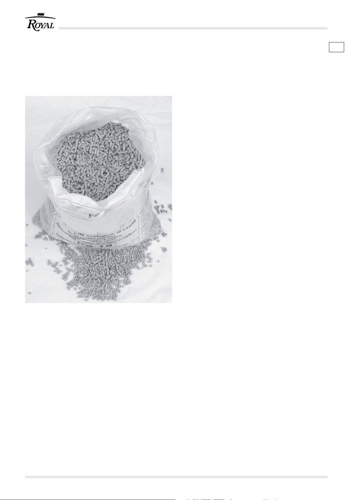
- Il pellet od ovuli di legno (Fig. 3.1) sono un
composto costituito da varie tipologie di legno
pressato con procedimenti meccanici nel rispetto
delle normative a tutela dell’ambiente.
È l’unico combustibile previsto per questo tipo
di stufa.
- L’efficienza e la potenzialità termica della stufa
possono variare in relazione al tipo ed alla qualità
degli ovuli in legno utilizzati.
La stufa richiede, per un corretto funzionamento,
ovuli che presentino le seguenti caratteristiche:
- dimensioni Ø 6 - 7 mm
- lunghezza max. 30 mm
- contenuto max. umidità 8 ÷ 9%
- La stufa è dotata di un serbatoio di contenimento
degli ovuli di legna della capacità indicata nella
tabella dati caratteristici.
Il portello di caricamento è posizionato nella parte
superiore.
)
- Il coperchio deve essere sempre apribile per
poter effettuare le cariche degli ovuli.
IT
Fig. 3.1
Per motivi di controllo della temperatura di esercizio
non è possibile il funzionamento a legna tradizionale.
È vietato usare la stufa come inceneritore.
3.2 STOCCAGGIO DEI PELLET
Il pellet deve essere conservato in un ambiente
!
asciutto e non troppo freddo.
Si consiglia di conservare alcuni sacchi di pellet nel
locale di utilizzo della stufa o in un locale attiguo purché
sia a temperatura e umidità accettabili.
Il pellet umido e/o freddo (5°C) riduce la potenzialità
termica del combustibile ed obbliga ad effettuare
maggiore manutenzione di pulizia del braciere
(materiale incombusto) e del focolare.
Porre particolare attenzione nello stoccaggio e
!
movimentazione dei sacchi di pellet. Deve essere
evitata la sua frantumazione e la formazione di
segatura.
Se viene immessa segatura nel serbatoio della stufa,
questa potrebbe causare il blocco del sistema di
carica del pellet.
cod. 004771021 - Claudia - Ivana - Antonella - Klima 1220
Page 21

GB D
3 FUEL CHARACTERISTICS AND A
DESCRIPTION OF THE STOVE
3 BRENNSTOFFEIGENSCHAFTEN
UND GERÄTEBESCHREIBUNG
3.1 FUEL CHARACTERISTICS
- The wood pellets (Fig. 3.1) are made with a
compound of different types of wood pressed by
means of mechanical procedures in compliance
with standards to safeguard the environment.
It is the only fuel to be used with this type of
stove.
- Stove heat output and efficiency may vary according
to the type and quality of wood pellets used.
For to work correctly you have to burn pellets with
the following characteristics:
- Ø 6 - 7 mm
- maximum 30 mm long
- max. humidity content: 8 ÷ 9%
- The wooden pellet storage box is on top of the
stove. The quantity of pellets for each stove model
is given in the technical features.
The hatch to open for filling up is at the top
)
- It must be possible to open the hatch lid at all
times for filling up with pellets.
Ordinary wood cannot be used for reasons linked to
controlling burning temperature.
3.1 BRENNSTOFFEIGENSCHAFTEN
- Die Pellets (Abb. 3.1) bestehen aus
verschiedenen Holzarten und werden durch ein
mechanisches Verfahren und unter Beachtung
der Umweltschutznormen aus Holzspänen
gepresst.
Für diesen Heizofen ist ausschließlich dieser
Brennstoff vorgesehen.
- Die Effizienz und Wärmeleistung des Heizofens
können je nach Art und Qualität der verwendeten
Holzpellets variieren.
Der benötigt für einen einwandfreien Betrieb
Pellets mit folgenden Eigenschaften:
- Maße Ø 6 - 7 mm
- Länge max. 30 mm
- Max. Feuchtigkeitsgehalt 8 ÷ 9%
- Im oberen Bereich des Heizofens befindet sich
der Behälter der Holzpellets.
Unter den technischen Merkmalen ist auch die
Menge für jedes Heizofenmodell angeführt.
Die Ladeklappe befindet sich im oberen Bereich.
)
- Der Deckel muss immer hindernisfrei zum
Einfüllen der Pellets geöffnet werden können.
It is forbidden to use the stove as an incinerator.
3.2 STORING THE PELLETS
Keep the pellets in a dry place, not too cold.
!
We suggest keeping a few bags of pellets in the same
room as the stove or in an adjacent room provided
both the temperature and humidity levels are
acceptable.
Damp and/or cold pellets (5°C) will not burn particularly
well and consequently the heat output will be reduced.
It also means more cleaning of the brazier (unburnt
material) and hearth.
Take particular care in storing and handling the bags
!
of pellets. Avoid breaking them, forming sawdust.
If sawdust builds up in the stove's pellet container, it
could block the pellet feeding system.
Aufgrund der Betriebstemperaturkontrolle kann der
Heizofen nicht mit traditionellem Holz beschickt
werden.
Es ist verboten, den Heizofen als
Verbrennungsanlage zu verwenden.
3.2 LAGERUNG DER PELLETS
Die Pellets müssen in einem trockenen, nicht allzu
!
kalten Raum gelagert werden.
Es ist empfehlenswert, einige Säcke Pellets im selben
Raum des Heizofens oder in einem nahe gelegenen
Raum mit geeigneter Temperatur und Feuchtigkeit
aufzubewahren.
Feuchte oder kalte (5°C) Pellets haben eine geringere
Heizleistung und bewirken, dass Kohlenbecken
(unverbranntes Material) und Feuerstelle häufiger
gereinigt werden müssen.
Bei der Lagerung und dem Handling der Pelletssäcke
!
immer Acht geben. Sie dürfen nicht in Sägespäne
zerkleinert werden.
Sägespäne im Behälter des Heizofens können zum
Blockieren des Pellets-Beschickungssystems führen.
21cod. 004771021 - Claudia - Ivana - Antonella - Klima 12
Page 22

A
B
D
L
E
C
Fig. 3.3.1
DELLA STUFA
A) Serbatoio pellet
B) Porta con maniglia
C) Camera di combustione
D) Cassetto cenere
E) Pannello comandi
F) Braciere
G) Ventilatore riscaldamento ambiente
È inserito nella parte posteriore della stufa. Si
avvia automaticamente quando la struttura della
stufa è calda e si spegne automaticamente
quando si raffredda.
F
H) Ventilatore espulsione fumi
Consente l’espulsione forzata dei fumi e
contemporaneamente l’aspirazione di aria
comburente al braciere.
Lavora in parallelo al sistema di caricamento e
varia la potenzialità di scarico dei fumi in funzione
della potenza termica.
I) Condotto d’aspirazione aria comburente
L) Vacuostato
M) Termostato a riarmo manuale, posto sul
montante della stufa.
N) Sistema di caricamento
È composto da un motoriduttore e da un dosatore
e permette la discesa del pellet nel braciere.
O) Scheda elettronica
P) Interruttore accensione stufa
Q) Resistenza elettrica
3.3 DESCRIZIONE DELLE PARTI PRINCIPALI
IT
O
N
G
Q
I
P
M
H
Fig. 3.3.2
4 MOVIMENTAZIONE E TRASPORTO
La stufa viene consegnata completa di tutte le parti
previste.
Fare attenzione alla tendenza allo sbilanciamento
della stufa.
Il baricentro della stufa è spostato verso la parte
!
anteriore.
Tenere ben presente quanto sopra anche durante lo
spostamento della stufa sul supporto di trasporto.
Durante il sollevamento evitare strappi o bruschi
movimenti.
Accertarsi che il carrello sollevatore abbia una
portata superiore al peso della stufa da sollevare.
Al manovratore dei mezzi di sollevamento spetterà
tutta la responsabilità del sollevamento dei carichi.
Fare attenzione che i bambini non giochino con i
componenti dell’imballo (es. pellicole e polistirolo).
Pericolo di soffocamento!
Fig. 3.3.3
cod. 004771021 - Claudia - Ivana - Antonella - Klima 1222
Page 23

GB D
3.3 DESCRIPTION OF THE STOVE'S MAIN PARTS
A) Pellet storage box
B) Door with handle
C) Combustion chamber
D) Ash box
E) Control panel
F) Hearth
G) Room heating fan
It is at the back of the stove. It starts automatically
when the stove structure is hot and switches
itself off when it has cooled down.
H) Smoke expulsion fan
It allows the forced expulsion of smoke and the
simultaneous intake of air for combustion to the
hearth.
It works in parallel with the loading system and
varies the volume discharged according to the
heat output.
I) Combustion air intake pipe
L) Vacuum switch
M) Manually resettable thermostat, placed on the
side of the stove.
N) Loading system
It consists of a gear motor and screw for dosing
the hearth with pellets.
O) Electronic card
P) Stove ignition switch
Q) Electric heating element
3.3 BESCHREIBUNG DER HAUPTBESTANDTEILE
DES HEIZOFENS
A) Pellets-Behälter
B) Tür mit Griff
C) Feuerraum
D) Aschenkasten
E) Bedienblende
F) Feuerbecken
G) Ventilator zur Raumheizung
Befindet sich an der Heizofenrückseite. Schaltet
sich bei warmem Heizofen automatisch ein und
beim Abkühlen wieder aus.
H) Rauchabsauggebläse
Ermöglicht die forcierte Rauchableitung und
gleichzeitig die Ansaugung von Verbrennungsluft
ins Feuerbecken.
Arbeitet parallel zur Beschickungsschnecke und
regelt den Rauchabzug je nach Wärmeleistung.
I) Ansaugungsleitung für Verbrennungsluft
L) Vakuummessgerät
M) Sicherheitstemperaturbegrenzer mit manueller
Rückstellung, im Seitenteil des Ofens platziert.
N) Beschickungssystem
Bestehend aus einem Getriebemotor und einer
Schnecke - ermöglich das Dosieren der Pellets
im Feuerbecken.
O) Elektronik-Platine
P) Schalter zum Einschalten des Heizofens
Q) Elektrischer Widerstand
4 HANDLING AND TRANSPORT
The stove is delivered complete with all the parts
specified.
Pay attention to the stove’s tendency to oscillate.
The stove’s barycentre is towards the front.
!
Bear the above well in mind also when moving the
stove on the transport stand.
Avoid sudden movements and sharp tugs when lifting
the stove.
Make sure the lifting capacity of the lift truck is more
than the weight of the stove.
The person manoeuvring the lifting means is held
completely responsible for lifting loads.
Do not let children play with the packaging materials
(film, polystyrene). Suffocation hazard!
4 HANDLING UND TRANSPORT
Das Gerät wird mit allen vorgesehenen Teilen geliefert.
Achtung, das Gerät kippt leicht.
Der Schwerpunkt des Heizofens liegt im vorderen
!
Bereich.
Dies ist auch beim Verstellen des Heizofens auf seinem
Transport-Untergestell zu beachten.
Nicht mit abrupten oder ruckartigen Bewegungen
anheben.
Sicherstellen, dass die Belastbarkeit des
Hubstaplers über dem Gerätegewicht liegt.
Der Bediener der Hebevorrichtung hat die gesamte
Verantwortung für das Anheben der Lasten.
Sicherstellen, dass keine Kinder mit den
Verpackungsteilen spielen (z.B. Folien und
Polystyrol). Es besteht Erstickungsgefahr!
23cod. 004771021 - Claudia - Ivana - Antonella - Klima 12
Page 24

5 PREPARAZIONE DEL LUOGO
DI INSTALLAZIONE
5.1 PRECAUZIONI PER LA SICUREZZA
La responsabilità delle opere eseguite nello spazio
d’ubicazione della stufa è, e rimane, a carico
dell’utilizzatore; a quest’ultimo è demandata anche
l’esecuzione delle verifiche relative alle soluzioni
d’installazione proposte.
L’utilizzatore deve ottemperare a tutti i regolamenti di
sicurezza locali, nazionale ed europei.
L’apparecchio dovrà essere installato su pavimenti
con adeguata capacità portante.
Le istruzioni di montaggio e smontaggio della stufa
sono riservate ai soli tecnici specializzati.
È sempre consigliabile che gli utenti si rivolgano al
nostro servizio di assistenza per le richieste di tecnici
qualificati.
Nel caso in cui intervengano altri tecnici si
raccomanda di accertarsi sulle loro reali capacità.
L’installatore, prima di avviare le fasi di montaggio o
di smontaggio della stufa, deve ottemperare alle
precauzioni di sicurezza previste per legge ed in
particolare a:
A) non operare in condizioni avverse;
B) deve operare in perfette condizioni psicofisiche e
deve verificare che i dispositivi antinfortunistici
individuali e personali, siano integri e
perfettamente funzionanti;
C) deve indossare i guanti antiinfortunistici;
D) deve indossare scarpe antiinfortunistiche;
E) deve usufruire di utensili muniti di isolamento
elettrico;
F) deve accertarsi che l’area interessata alle fasi di
montaggio e di smontaggio sia libera da ostacoli.
IT
5.2 CONSIDERAZIONI GENERALI
Molti sono i fattori che concorrono per rendere efficace
la combustione in termini di prestazioni termiche e
basse emissioni di sostanze inquinati (CO Monossido di carbonio).
Alcuni fattori dipendono dall’apparecchiatura nella
quale avviene la combustione
da caratteristiche ambientali, di installazione e dal
grado di manutenzione ordinaria effettuato sul
prodotto.
Alcuni fattori importanti sono:
- aria comburente;
caratteristiche del sistema di evacuazione dei
-
prodotti della combustione;
- qualità del pellet (umidità e dimensioni).
Nei paragrafi successivi sono riportate alcune
indicazioni da rispettare per ottenere il massimo
rendimento del prodotto acquistato.
cod. 004771021 - Claudia - Ivana - Antonella - Klima 1224
altri invece dipendono
Page 25

GB D
5 PREPARING THE PLACE OF
INSTALLATION
5 VORBEREITUNG DES
INSTALLATIONSORTS
5.1 SAFETY PRECAUTIONS
O The responsibility for any work done in the space
where the stove is to be installed is, and remains,
user’s. The user is also entrusted with carrying out
the checks regarding the proposed installation
solutions.
The user must comply with all the local, national and
European rules and regulations.
The appliance must be installed on a floor with an
adequate carrying capacity.
Stove assembly and dismantling instructions are for
specialized technicians only.
It is always advisable for the user to call our assistance
service when they need qualified technicians.
If other technicians are called in, please make sure
they are truly qualified.
Before starting the assembly or dismantling phases
of the stove, the installer must comply with the safety
precautions as established by law, and in particular
as regards:
A) he must not work in adverse conditions;
B) he must be in perfect psychophysical condition to
work and ensure that the individual and personal
accident prevention devices are sound and in
perfect working order;
C) he must wear accident prevention gloves;
D) he must wear safety shoes;
E) he must use electrically insulated tools;
F) he must make sure that the area he is working in
for assembling/dismantling the stove is free from
obstacles.
5.2 GENERAL CONSIDERATIONS
There are many factors that contribute to good
combustion in terms of heat performance and low
emission of polluting substances (CO - carbon
monoxide).
Some of these factors depend on the stove itself while
others depend on the environmental and installation
conditions and on the routine maintenance carried
out.
Some of the important factors are:
- air for combustion;
features of the combustion products evacuation
-
system;
- pellet quality (humidity content and size).
Some indications are given in the following
paragraphs that should be complied with to achieve
maximum stove performance.
5.1 VORBEUGENDE SICHERHEITSMASSNAHMEN
Die Verantwortung für die Arbeiten im
Aufstellungsraum des Heizofens ist und bleibt die
des Benutzers; diesem wird auch die Ausführung
der Kontrolle bezüglich der Installationsvorschläge
übertragen.
Der Benutzer hat alle örtlichen, nationalen und
europäischen Sicherheitsregelungen einzuhalten.
Das Gerät muss auf einem Fußboden mit
entsprechender Ladefähigkeit installiert werden.
Die Anleitung zur Montage und zum Zerlegen des
Heizofens ist ausschließlich fürs Fachpersonal
vorbehalten.
Es ist immer empfehlenswert, sich für die Anforderung
von qualifizierten Technikern an eine unserer
Kundendienststellen zu wenden.
Sollten andere Techniker eingreifen, sind deren
Fähigkeiten unbedingt sicherzustellen.
Der Installateur hat vor der Montage oder dem
Zerlegen des Geräts alle gesetzlich vorgesehenen
Sicherheitsmaßnahmen und insbesondere die
Folgenden zu beachten:
A) Nicht bei ungünstigen Bedingungen vorgehen;
B) Unter einwandfreien psychophysischen
Bedingungen arbeiten und sicherstellen, dass die
individuellen und persönlichen
Unfallverhütungsvorrichtungen ganz sind und
einwandfrei funktionieren;
C) Schutzhandschuhe tragen;
D) Schutzschuhe tragen;
E) Elektrisch isoliertes Werkzeug verwenden;
F) Sicherstellen, dass der für die Montage bzw. das
Zerlegen nötige Bereich keine Hindernisse
aufweist.
5.2 ALLGEMEINE ANMERKUNGEN
Viele Faktoren spielen für eine im Sinne von
Wärmeleistung und niedrige Schadstoffabgabe (CO Kohlenmonoxyd) effiziente Verbrennung eine
bedeutende Rolle.
Einige Faktoren hängen vom Gerät ab, in dem die
Verbrennung vor sich geht, andere hingegen hängen
von den Umwelt- und Installationsbedingungen bzw.
der Regelmäßigkeit der Gerätewartung ab.
Einige wichtige Faktoren sind:
- Verbrennungsluft;
Eigenschaften des Rauchabzugsystems.
-
- Qualität der Pellets (Feuchtigkeit und Größe).
In den anstehenden Absätzen sind einige Anweisungen
enthalten, die einzuhalten sind, damit der Heizofen
mit maximaler Leistung funktioniert.
25cod. 004771021 - Claudia - Ivana - Antonella - Klima 12
Page 26

B
20 cm
A
30 ÷ 50 cm
MIN
20 cm
20 cm
C
D
Fig. 5.3.1
P A
5.3 LUOGO DI INSTALLAZIONE DELLA STUFA
In figura (Fig. 5.3.1) sono indicate le distanze minime
che devono essere rispettate nel posizionamento
della stufa rispetto a materiali e oggetti combustibili.
A) Parete adiacente.
B) Parete posteriore.
C) Parete laterale.
D) Protezione del pavimento.
Proteggete dalle radiazioni calde del fuoco tutte le
strutture che potrebbero incendiarsi se esposte a
eccessivo calore.
Pavimenti in legno o costituiti da materiale infiammabile,
devono essere protetti con materiale non combustibile;
ad esempio lamiera con spessore 2-3 mm.
La protezione dovrà ricoprire tutta la zona del
pavimento davanti alla stufa.
La stufa può essere installata fra due pareti.
La distanza minima da rispettare tra la stufa e le
superfici delle pareti deve essere di 20 cm.
Eventuali travi in legno situate al di sopra della stufa
vanno protette con materiale ignifugo.
Prevedere uno spazio tecnico accessibile per
!
eventuali manutenzioni.
IT
5.4 ARIA COMBURENTE
La stufa, durante il suo funzionamento, preleva una
!
quantità di aria (se pur modesta) dall’ambiente in cui
è collocata; quest’aria dovrà essere reintegrata
attraverso una presa d’aria esterna al locale stesso
(Fig. 5.4.1 - PA = Presa d’Aria).
Fig. 5.4.1
G
C
S
Se la parete posteriore della stufa è una parete
esterna, realizzare un foro per l’aspirazione dell’aria
comburente ad una altezza dal suolo di circa 20-30
cm.
Esternamente deve essere messa una griglia di
aerazione permanente; in zone particolarmente
ventose ed esposte alle intemperie, prevedere una
protezione antipioggia ed antivento.
Accertarsi che la presa d'aria sia posizionata in modo
da non essere ostruita accidentalmente.
Nel caso fosse impossibile realizzare la presa d’aria
esterna nella parete posteriore alla stufa (parete non
perimetrale) deve essere realizzato un foro in una parete
esterna del locale dove viene posizionata la stufa.
Se non fosse possibile realizzare la presa d’aria
esterna nel locale, è possibile realizzare il foro esterno
in un locale adiacente purché comunicante in maniera
permanente con griglia di transito.(Fig. 5.4.2 - C =
Cassonetto, G = Griglia, S = Serranda)
La normativa UNI 10683 vieta il prelievo di aria
comburente da garage, magazzini di materiale
combustibile o ad attività con pericolo di incendio.
Fig. 5.4.2
Il foro di presa d’aria esterna comburente non deve
essere collegato alla stufa mediante tubazione.
Qualora nel locale ci siano altri apparecchi di
riscaldamento le prese dell’aria comburente devono
garantire il volume necessario di aria al corretto
funzionamento di tutti i dispositivi.
cod. 004771021 - Claudia - Ivana - Antonella - Klima 1226
Page 27

GB D
5.3 WHERE TO INSTALL THE STOVE
Figure 5.3.1 shows the minimum clearance there
should be around the stove in relation to materials
and flammable objects.
A) Adjacent wall.
B) Rear wall.
C) Side wall.
D) Floor protection.
Protect all structures that could burn if exposed to the
heat radiated by the stove.
Wood flooring or floors made with flammable
materials must be protected with a material that will
not burn like, for instance, a 2-3 mm thick sheet of
metal.
Such protection should cover the whole floor in front of
the stove.
The stove can be installed between two walls.
The minimum clearance between the stove and wall
surfaces must be 20 cm.
If there are wooden beams above the stove they must
be protected with fire-retardant material.
Leave enough room for maintenance.
!
5.3 AUFSTELLUNGSORT DES HEIZOFEN
In der Abbildung (Abb. 5.3.1) sind die Mindestabstände
zu brennbaren Materialien oder Gegenständen
angegeben, die bei der Aufstellung des Heizofens
einzuhalten sind.
A) Angrenzende Wand.
B) Hintere Wand.
C) Seitliche Wand.
D) Fußbodenschutz.
Alle Strukturen, die Feuer fangen können, vor der Hitze
des Feuers schützen.
Fußböden aus Holz oder anderen brennbaren
Materialien müssen mit einem feuerfesten Material
abgedeckt werden; z.B. Ein Blech mit 2-3 mm Stärke.
Das Schutzblech muss den gesamten
Fußbodenbereich vor dem Heizofen abdecken.
Der Heizofen kann zwischen zwei Wänden installiert
werden.
Der Mindestabstand zwischen dem Heizofen und den
angrenzenden Oberflächen muss 20 cm betragen.
Eventuelle Holzbalken über dem Heizofen sind mit
feuerfestem Material zu verkleiden.
Genügend Freiraum für eventuelle
!
Wartungseingriffe lassen.
5.4 AIR FOR COMBUSTION
When the stove is working it takes a quantity of air
!
(although it is not very much) from the room it is installed
in; there should be an external air intake to make sure
there is always enough air in the room (Fig. 5.4.1 - PA
= Air Intake).
If the rear wall of the stove is an external wall, drill an
hole for the intake of air for combustion about 20-30
cm from the floor.
Fit a permanent aeration grille on the outside of the air
intake. In areas that are windy and exposed to the
weather, it should also be protected against the rain
and wind.
Make sure that the air intake is located in a way that it
cannot be obstructed by accident.
If an air intake cannot be made on the rear wall of the
stove (a non-perimeter wall) then drill one in an
external wall of the room where the stove is installed.
If it is impossible to have an external air intake in the
room, an external hole can be made in an adjacent
room provided it communicates permanently with a
transit grille. (Fig. 5.4.2 - C = Box, G = Grille, S =
Damper)
The UNI 10683 standard forbids taking air for
combustion from garages, rooms where flammable
materials are stored or where there is danger of
fire.
The external intake hole for combustion air must
not be connected to the stove with a pipe.
5.4 VERBRENNUNGSLUFT
Der Heizofen entnimmt dem Raum, in dem er steht,
!
während des Betriebs eine gewisse, wenn auch geringe
Luftmenge; diese Luft muss durch eine Lüftungsöffnung
von außen wieder dem Raum zugeführt werden (Abb.
5.4.1 - PA = Lüftungsöffnung).
Sollte die Wand hinter dem Heizofen eine Außenwand
sein, auf ca. 20-30 cm vom Boden eine Öffnung zur
Zuführung der Verbrennungsluft vorsehen.
Außen ist ein fixes Schutzgitter anzuordnen; an
besonders windigen bzw. der Witterung ausgesetzten
stellen ist ein Regen- und Windschutz vorzusehen.
Die Frischluftzufuhr muss so durchgeführt werden, dass
es auf keinen Fall zufällig verstopft werden kann.
Sollte es nicht möglich sein, die Lüftungsöffnung nach
außen hinter dem Heizofen anzulegen, d.h. heißt, wenn
die Wand hinter dem Heizofen keine Außenwand ist, muss
die Öffnung an einer anderen Außenwand im Raum, in
dem der Heizofen aufgestellt ist, angeordnet werden.
Sollte es nicht möglich sein, die Lüftungsöffnung nach
außen in diesem Raum anzulegen, kann die Öffnung
in einem angrenzenden Raum angeordnet werden,
wobei dieser Raum jedoch ständig durch ein
Lüftungsgitter mit dem Aufstellungsraum des
Heizofens in Verbindung stehen muss. (Abb. 5.4.2 - C
= Kasten, G = Gitter, S = Rollladen)
Die UNI-Norm 10683 untersagt die Frischluftzufuhr
aus Garagen, Brennstoff-Lagerräumen oder
Räumen in denen feuergefährliche Aktivitäten
ausgeführt werden.
If there are other heating appliances in the same
room, the combustion air intakes must be able to
guarantee the necessary volume of air to ensure
correct operation of all the devices.
Die Öffnung zur Verbrennungsluftzufuhr darf nicht
mittels Rohrleitung an den Heizofen angeschlossen
werden.
27cod. 004771021 - Claudia - Ivana - Antonella - Klima 12
Page 28
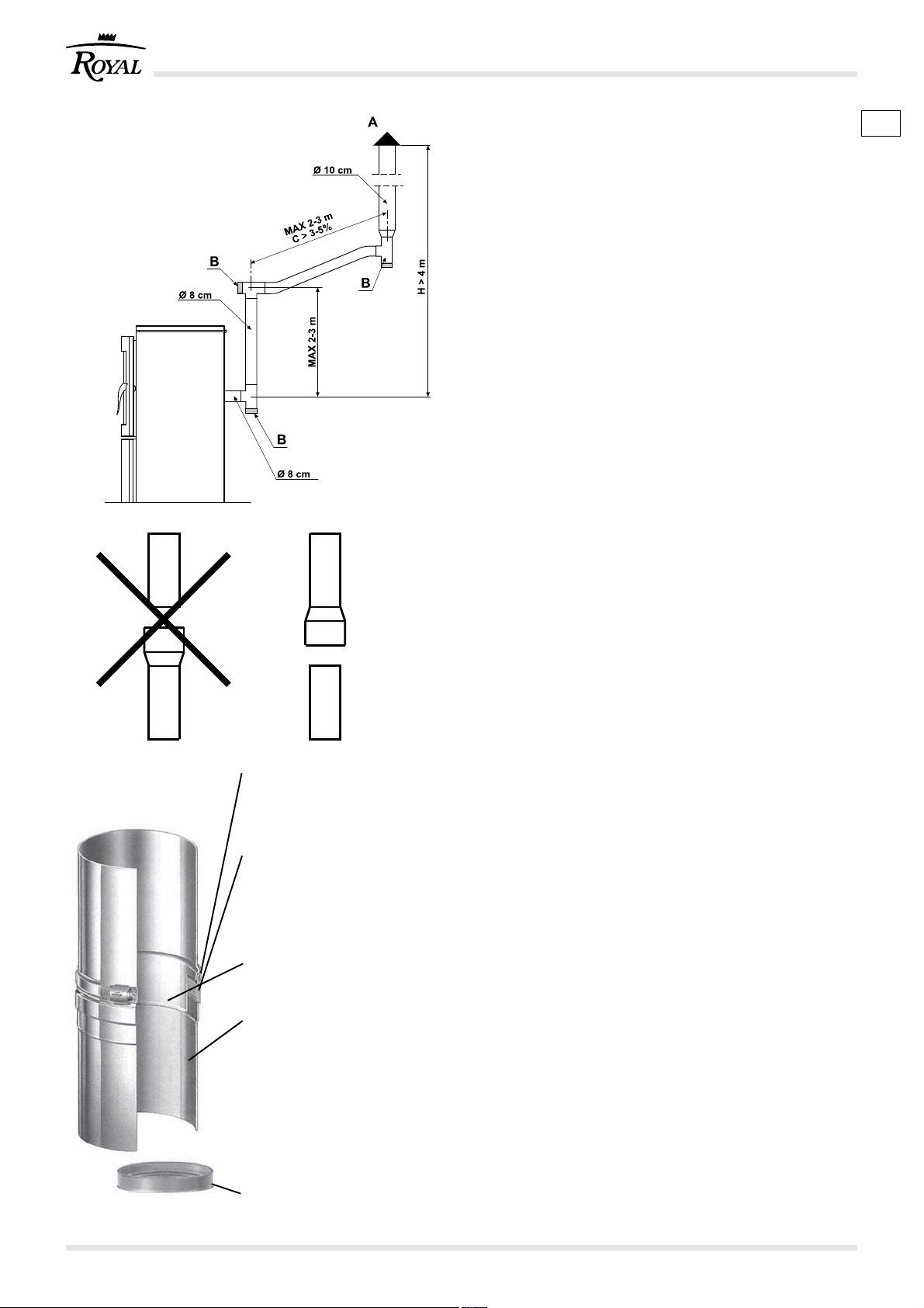
A) Comignolo antivento
Windproof chimney top
Windschutz-Schornstein
B) Ispezione, Inspection, Inspektion
C) Pendenza, Slope, Neigung
H) Altezza, Height, Höhe
A) Fascetta di sicurezza a
serraggio rapido.
Quick connect safety clamp.
Sicherheitsschelle mit
Schnellverschluss.
B) Alloggiamento guarnizione per
funzionamento in
sovrapressione.
Seal housing for working in
overpressure.
Dichtungssitz für Betrieb in
Überdruck.
C) Sistema di connessione “a
bicchiere”.
“Socket” connecting system.
Muffenverbindung.
D) Acciaio inossidabile AISI 316L.
Finitura lucida BA con saldatura
longitudinale certificata, al laser
o al TIG.
AISI 316L stainless steel.
BA gloss finish with certified
laser or tig longitudinal welding.
Glänzende Ausführung BA mit
zertifizierter Längsschweißung
- Laser- oder TIG-Technik.
E) Guarnizione siliconica.
Silicone seal.
Silikondichtung.
Fig. 5.5.1
Fig. 5.5.2
Fig. 5.5.3
Nel caso in cui nella stanza dove è ubicata la stufa
siano presenti e funzionanti uno o più ventilatori di
estrazione (cappe di aspirazione) si potrebbero
verificare malfunzionamenti alla combustione
causati dalla scarsità di aria comburente.
5.5 SCARICO FUMI
La stufa funziona con la camera di combustione in
depressione è indispensabile assicurarsi che lo
scarico sia a tenuta ermetica.
- Dopo aver scelto il luogo adatto per l’installazione
e considerando le misure riportate nel paragrafo
5.3, individuare il percorso della tubazione di
scarico dei fumi.
- I tubi da utilizzare per lo scarico dei fumi devono
essere rigidi in acciaio alluminato verniciato
(spessore minimo 1,5 mm) o in acciaio inox
(spessore minimo 0,5 mm) con diametro
nominale di 8 cm con guarnizioni (fino a 5 metri di
percorso) o di 10 cm con guarnizioni (con percorsi
superiori a 5 metri) (Fig. 5.5.1).
È consigliato isolare la tubazione con materiale
isolante (lana di roccia con uno spessore minimo
di 2 cm) oppure utilizzare tubi in acciaio a doppia
parete, escluso eventualmente il primo tratto
verticale se interno.
- È obbligatorio realizzare un primo tratto verticale
!
!
di 1,5 metri minimi per garantire la corretta
espulsione dei fumi.
Si consiglia di effettuare un massimo di 5/6 variazioni
di direzione utilizzando delle curve a 45-90° o dei
raccordi e Tee.
- I tubi devono essere collegati con l’attacco
femmina verso il basso per garantire la tenuta al
fumo e la condensa mediante guarnizione (Fig.
5.5.2).
- Utilizzare sempre un raccordo a Tee con tappo di
ispezione ad ogni variazione orizzontale e verticale
del percorso di scarico fumi.
- I tratti orizzontali devono avere una lunghezza
massima di 2-3 m con una pendenza verso l’alto
del 3-5%.
- Ancorare le tubazioni con appositi collari alla
parete.
Il raccordo di scarico dei fumi NON DEVE ESSERE
collegato:
- ad una canna fumaria utilizzata da altri
generatori (caldaie, stufe, caminetti, ecc....);
- a sistemi di estrazione d’aria (cappe, sfiati,
ecc....) anche se “intubato”.
È vietato installare valvole di interruzione e di tiraggio.
Con un percorso di scarico fumi superiore a 5 metri
e in condizioni di scarso tiraggio (presenza di molte
curve, terminale di scarico inadeguato, ecc.)
l’espulsione dei fumi può non essere ottimale. In
questi casi sarà necessario effettuare la variazione
dei parametri di funzionamento (espulsione fumi e
carica pellet) per adattare la stufa alle reali
caratteristiche impiantistiche della canna fumaria.
Contattare il servizio di assistenza tecnica.
IT
cod. 004771021 - Claudia - Ivana - Antonella - Klima 1228
Page 29

In case in the room where the stove is installed there
GB D
are one or more extractors (such as kitchen
aspirators), some troubles to the combustion due
to the lack of comburent air might occur.
Sollten im gleichen Raum noch weitere Heizgeräte
vorhanden sein, müssen die Lüftungsöffnungen für
die Zufuhr der Verbrennungsluft das für den
korrekten Betrieb aller Geräte notwendige Volumen
gewährleisten.
5.5 FLUE
The stove works with the combustion chamber
under vacuum: it is essential to ensure that the
discharge is HERMETICALLY SEALED.
- Once you have chosen the most suitable place to
install the stove, and considering the
measurements given in paragraph 5.3, see
exactly where the flue pipe must go.
- The pipes to use for discharging smoke must be
in varnished rigid aluminate steel (minimum 1.5
mm thick) or in stainless steel (minimum 0.5 mm
thick) with a nominal diameter of 8 cm with seals
(up to a maximum length of 5 metres) or 10 cm
with seals (for lengths beyond 5 metres) (Fig.
5.5.1).
We recommend either lagging the pipes (with rock
wool minimum 2 cm thick) or using dual-walled
steel pipes, except for the first vertical section if
indoors.
- the first section must be vertical (at least 1.5
!
metres) to guarantee correct expulsion of the
smoke.
Up to a maximum of 5-6 variations in direction are
recommended, utilising 45-90° eblows or couplings
and T-pieces.
- the pipes must be connected with a female fitting
downwards to guarantee it is smoke and
condensate tight with a seal (Fig. 5.5.2).
- always use a union tee with inspection cap at
each horizontal and vertical variation in the smoke
discharge path.
- the horizontal sections must be no longer than 23 m with an upward slant of 3-5%.
- anchor the pipes to the wall with the relative
collars.
The smoke discharge fitting MUST NOT BE
connected:
- to a flue used by other heat generators (boilers,
stoves, fireplaces, etc.);
- to air extraction systems (hoods, breather pipes,
etc.) even if ducted.
Falls im Raum wo der Ofen installiert wurde, ein oder
mehr Absaugsysteme (wie Küchensauggebläsen)
sich befinden, könnten einige Störungen der
Verbrennung wegen Mängel an Verbrennungsluft
sich ereignen.
5.5 RAUCHABZUGSLEITUNG
Der Heizofen funktioniert mit Feuerraum in
Unterdruck - unbedingt sicherstellen, dass die
Abgasleitung HERMETISCH VERSCHLOSSEN ist.
- Nachdem der geeignete Platz für die Installation
des Heizofens gewählt wurde, unter Beachtung der
Maße aus Absatz 5.3 die geeignete Verlegung der
Abgasleitung ausfindig machen.
- Die Rohre für den Rauchabzug müssen aus
starrem, lackiertem Aluminiumstahl (mindestens
1,5 mm Stärke) oder Edelstahl (mindestens 0,5 mm
Stärke) mit 8 cm Nenndurchmesser mit Dichtungen
(bis zu 5 m langen Strecken) oder 10 cm mit
Dichtungen (für Strecken über 5 m) gefertigt
werden (Abb. 5.5.1).
Es ist empfehlenswert, die Rohrleitung mit
geeignetem Material (Steinwolle mit einer
Mindeststärke von 2 cm) zu isolieren oder
doppelwandige Stahlrohre zu verwenden ausgeschlossen davon ist natürlich der erste
vertikale Streckenabschnitt, wenn er innen verläuft.
- Zur korrekten Rauchableitung muss die
!
Rohrleitung mindestens die ersten 1,5 Meter
vertikal verlegt werden
Es ist empfehlenswert, maximal 5/6
Richtungsänderungen einzubauen und dafür 45-90°Krümmungen bzw. T-Anschlüsse zu verwenden.
- Die Rohre müssen mit der Muffe nach unten
angeschlossen werden, damit kein Rauch bzw.
Kondenswasser (Dichtung vorsehen) austreten
kann (Abb. 5.5.2).
- Immer einen prüfbaren T-Anschluss bei jeder
vertikalen oder horizontalen Streckenänderung der
Abgasleitung verwenden.
- Die horizontalen Strecken dürfen max. 2-3 m lang
sein und 3-5% Steigung aufweisen.
- Die Rohre mit geeigneten Schellen an der Wand
befestigen.
It is forbidden to install shutdown and draught valves.
If the smoke discharge path is longer than 5 metres
!
and the draught is not very good (many bends,
inadequate discharge terminal, etc.), smoke
discharge will not be optimal. In such cases the
operating parameters will have to be altered (smoke
expulsion and pellet loading) to adapt the stove to
the flue’s characteristics. Contact the technical
assistance centre.
Der Anschluss der Abgasleitung darf nicht an
folgende Leitungen angeschlossen werden:
- einen bereits durch andere Heizungen (Kessel,
Heizöfen, Kamine usw.) verwendeten
Rauchfang;
- an Entlüftungssysteme (Dunstabzugshauben,
Entlüftung usw.), auch nicht, wenn extra
verlaufend.
29cod. 004771021 - Claudia - Ivana - Antonella - Klima 12
Page 30

Fig. 5.5.4
5.5.1 Scarico a tetto mediante canna fumaria
La canna fumaria per lo scarico dei fumi deve essere
realizzata in osservanza alle norme EN 10683 - EN
1856-1-2 - EN 1857 - EN 1443 - EN 13384-1-3 - EN
12391-1 sia per quanto riguarda le dimensioni che
per i materiali utilizzati nella sua costruzione.
Canne fumarie FATISCENTI, costruite con materiale
non idoneo (fibrocemento, acciaio zincato, ecc... con
superficie interna ruvida e porosa) sono fuorilegge e
pregiudicano il buon funzionamento della stufa.
Lo scarico dei fumi attraverso la canna fumaria
tradizionale (Fig. 5.5.4) può essere fatto purché siano
rispettate le seguenti regole:
- assicurarsi sullo stato di manutenzione della
canna fumaria; in caso di canna fumaria vecchia
si consiglia di provvedere al risanamento
introducendo una tubazione in acciaio
opportunamente isolata (lana di roccia,
vermiculite).
- I fumi possono essere scaricati direttamente in
canna fumaria solo se questa ha una sezione
massima di 15 × 15 cm o diametro 15 cm ed è
provvista di uno sportello di ispezione.
A) Comignolo antivento.
B) Sezione massima di 15 × 15 cm o diametro 15
cm e altezza massima di 4 - 5 metri.
C) Sigillare.
D) Ispezione.
- In caso di canna fumaria di sezione maggiore è
!
necessario “intubare” la canna fumaria con una
tubazione in acciaio (con diametro in funzione
del percorso) opportunamente isolata (Fig. 5.5.5).
- Assicurarsi che il collegamento alla canna
fumaria in muratura sia opportunamente sigillato
- Evitare il contatto con materiale combustibile (travi
in legno) e in ogni caso provvedere al loro
isolamento con materiale ignifugo.
A) Vermiculite e/o lana di roccia.
B) Tubazione in acciaio.
C) Pannello di chiusura.
IT
Fig. 5.5.5
cod. 004771021 - Claudia - Ivana - Antonella - Klima 1230
Page 31

5.5.1 Discharge through the roof with a flue
GB D
The flue for discharging smoke must be made in
compliance with the EN 10683 - EN 1856-1-2 - EN
1857 - EN 1443 - EN 13384-1-3 - EN 12391-1
standards both as regards the dimensions and the
materials used to make it.
DETERIORATING flues made with unsuitable
materials (such as asbestos cement, galvanised
steel, etc., with a rough or porous internal surface)
are illegal and can jeopardise the correct operation of
the stove.
Smoke may be discharged through a traditional flue
(fig. 5.5.4) provided the following rules are observed:
- make certain the flue is in a good state of repair. If
the flue is old we suggest inserting a suitably
lagged steel pipe (rock wool, vermiculite).
- Smoke can be discharged directly through the flue
only if it has a maximum cross section of 15 × 15
cm or 15 cm in diameter and is fitted with an
inspection hatch.
A) Windproof chimney top.
B) Maximum cross section of 15 × 15 cm or 15 cm in
diameter and maximum 4-5 metres high.
C) Seal.
D) Inspection.
- If the flue section is bigger it must be ducted
!
using an adequately insulated steel pipe (the
diameter depends on the length of the path) (Fig.
5.5.5).
- Make sure the connection to the brickwork flue is
perfectly sealed.
- Avoid contact with flammable materials (timber
beams) which must, in any case, be insulated
with a fire-retardant material.
A) Vermiculite and/or rock wool.
B) Steel piping.
C) Closing panel.
5.5.1 Abzug am Dach mit Rauchfang
Die Installation von Absperrventilen und
Luftregelklappen ist verboten.
Bei einer über 5 Meter langen Rauchabzugsleitung
!
und bei schlechten Abzugsbedingungen (mehrfache
Krümmungen, Schornstein nicht geeignet usw.),
kann der Rauchabzug nicht optimal erfolgen. In
diesem Fall sind die Betriebsparameter zu ändern
(Rauchabzug und Pelletsbeschickung), um den
Heizofen an die realen Anlageneigenschaften des
Rauchfangs anzupassen. Den technischen
Kundendienst dafür kontaktieren.
Abzug am Dach mit „traditionellem“ Rauchfang Der
Rauchfang muss bezüglich der Maße und der
verwendeten Materialien den in den Normen EN 10683
- EN 1856-1-2 - EN 1857 - EN 1443 - EN 13384-1-3 EN 12391-1 genannten Auflagen entsprechen.
BAUFÄLLIGE Rohre aus ungeeignetem Material, wie
Asbestzement, verzinktem Stahl usw... mit rauen und
porösen Innenflächen entsprechen nicht den geltenden
Gesetzen und beeinträchtigen den einwandfreien
Betrieb des Heizkamins.
Die Abgasleitung über einen traditionellen Rauchfang
(Abb. 5.5.4) kann unter Beachtung folgender Regeln
erfolgen:
- den Rauchfang auf seinen Zustand prüfen; bei
einem alten Rauchfang ist eine Sanierung durch
Einführung eines isolierten Stahlrohrs (mit
Steinwolle oder Vermiculit) empfehlenswert.
- Der Rauch kann nur dann direkt in den Rauchfang
abgeleitet werden, wenn dieser einen maximalen
Querschnitt von 15 × 15 cm oder einen
Durchmesser von 15 cm aufweist und über eine
Inspektionsklappe verfügt.
A) Windschutzkamin.
B) Maximaler Querschnitt 15×15 cm oder
Durchmesser 15 cm, maximale Höhe 4-5 Meter.
C) Versiegeln.
D) Inspektion.
- Bei einem Rauchfang mit größeren Innenmaßen
!
muss ein dementsprechend isoliertes Stahlrohr
(mit Durchmesser je nach Strecke) eingeführt
werden (Abb. 5.5.5).
- Sicherstellen, dass der Anschluss an den
gemauerten Rauchfang versiegelt ist
- Den Kontakt mit brennbarem Material (Holzbalken)
vermeiden und diese auf jeden Fall mit feuerfestem
Material isolieren.
A) Vermiculit bzw. Steinwolle.
B) Stahlrohr.
C) Verschlussplatte.
31cod. 004771021 - Claudia - Ivana - Antonella - Klima 12
Page 32

6 INSTALLAZIONE
IT
AB
Fig. 6.1.1
L'installazione deve essere effettuata da personale
qualificato in osservanza alla norma EN 10683-05.
6.1 LIVELLAMENTO DELLA STUFA
La stufa deve essere livellata, con l’ausilio di un’asta
a bolla, agendo sui piedini di regolazione (Fig. 6.1.1).
A B = Asta a Bolla
6.2 ALLACCIAMENTO AGLI IMPIANTI
6.2.1 Collegamento elettrico
È sufficiente collegare la stufa all’impianto elettrico
attraverso la spina in dotazione.
)
Il collegamento elettrico (spina) deve essere
facilmente accessibile anche dopo l’installazione
della stufa.
Se il cavo di alimentazione risulta danneggiato deve
!
essere sostituito dal servizio di assistenza tecnica
o da un tecnico qualificato in modo da prevenire
ogni rischio.
Fig. 6.2.1
6.2.1.1 Messa a terra
È obbligatorio che l’impianto sia provvisto di messa
a terra e di interruttore differenziale in ottemperanza
alle leggi vigenti (Fig. 6.2.1).
Il condotto di scarico fumi deve essere dotato di
!
proprio collegamento a terra.
6.2.1.2 Avviamento
Per l’avviamento posizionare l’interruttore su “I”
(acceso) (Fig. 6.2.2).
Fig. 6.2.2
cod. 004771021 - Claudia - Ivana - Antonella - Klima 1232
Page 33

GB D
6 INSTALLATION
6 INSTALLATION
The installation must be carried out by qualified
personnel in compliance with the EN 10683-05.
6.1 LEVELLING THE STOVE
The stove must be levelled by turning the adjustment
feet (Fig. 6.1.1), with the aid of a spirit level.
A B = Spirit Level
6.2 CONNECTION TO SYSTEMS
6.2.1 Electrical connection
Simply connect the stove to the electricity mains with
the plug supplied.
)
The electrical connection (plug) must be easy to
access also after the stove has been installed.
If the power lead is damaged it must be replaced by
!
the technical assistance service or a qualified
electrician to prevent all risks.
Die Installation muss von qualifiziertem Fachpersonal
durchgeführt werden den in den Normen EN 10683-
05.
6.1 NIVELLIEREN DES HEIZOFENS
Der Heizofen muss unter Einsatz einer Wasserwaage
anhand der Stellfüße nivelliert werden (Fig. 6.1.1).
A B = Wasserwaage
6.2 VERSCHIEDENE ANSCHLÜSSE
6.2.1 Stromanschluss
Den Heizofen einfach mit dem Stecker an die häusliche
Stromleitung anschließen.
)
Der Elektroanschluss (Stecker) muss auch nach der
Installation des Heizofens mühelos zugänglich
sein.
Sollte das Netzkabel beschädigt sein, muss es vom
!
Personal des Technischen Kundendiensts oder von
einem Fachmann ersetzt werden, um jedes Risiko
zu vermeiden.
6.2.1.1 Earthing
The system must be earthed and fitted with a circuit
breaker as provided for by current laws (Fig. 6.2.1).
The flue must have its own earth connection.
!
6.2.1.2 Starting
To start, press the switch down, "I", (On) (Fig. 6.2.2).
6.2.1.1 Erdung
Die Anlage muss obligatorisch mit einer Erdung und
einem Schutzschalter gemäß den gültigen
Bestimmungen ausgestattet sein (Abb. 6.2.1).
Die Rauchabzugsleitung muss direkt mit dem
!
Fußboden verbunden sein.
6.2.1.2 Start
Für die Inbetriebnahme den Schalter auf „I“ (ein)
stellen (Abb. 6.2.2).
33cod. 004771021 - Claudia - Ivana - Antonella - Klima 12
Page 34

Fig. 6.3.1
6.3 COLLEGAMENTO AD UN IMPIANTO DI
DISTRIBUZIONE DELL’ARIA
(solo per i modelli canalizzabili o provvisti di kit di
canalizzazione)
E’ possibile collegare i modelli ad aria canalizzabili
ad un condotto di distribuzione del calore. Si consiglia
di utilizzare preferibilmente condotti a sezione circolare
con interno liscio e adeguatamente isolati per evitare
dispersioni di calore.
Nel caso una stufa canalizzabile o predisposta per
montare il kit di canalizzazione, non sia collegata ad
un condotto di distribuzione del calore, assicurarsi
che il deviatore sia in posizione tale da convogliare
l’aria nell’ambiente in cui è installata la stufa stessa.
S
TUFE CANALIZZABILI
Attraverso l’attrezzo in dotazione o alla leva di
deviazione dell’aria (in base al modello) è possibile
agire sul comando per deviare il flusso dell’aria calda
dall’ambiente dove è installata la stufa al condotto di
canalizzazione e viceversa (Fig. 6.3.1).
Per collegare la stufa all’impianto di canalizzazione
rimuovere il tappo svitando le due viti di fissaggio che
fissano il tappo di chiusura della canalizzazione, sul
posteriore della stufa.
TUFE PREDISPOSTE PER IL KIT DI CANALIZZAZIONE
S
Per il montaggio del kit di canalizzazione far riferimento
alle istruzioni contenute nel kit stesso.
è possibile deviare il flusso dell’aria dall’ambiente al
condotto di canalizzazione, attraverso l’attrezzo in
dotazione del kit, agendo sul comando posto sul
frontale della stufa.
IT
cod. 004771021 - Claudia - Ivana - Antonella - Klima 1234
Page 35

GB D
6.3 CONNECTION TO AN AIR DISTRIBUTION
SYSTEM
(only for ducted models or provided with ducting kit)
Ducted models can be connected to a hot air
distribution system. The pipes used should preferably
be circular with a smooth inner surface and suitably
insulated to avoid heat loss.
For ducted stoves or models ready to fit a ducting
kit that are not connected to a hot air distribution
pipe, make sure the deflector is positioned so as to
deviate the hot air into the room where the stove is
installed.
D
UCTED STOVES
Using the tool supplied or the air deflector lever (based
on the model), the flow of hot air can be deviated from
the room where the stove is installed to the ducting,
and vice-versa (Fig. 6.3).
To connect the stove to the ducting system, remove
the cap by unscrewing the two fastening screws that
secure the duct closure cap on the rear of the stove
(Fig. 6.4).
TOVES READY TO FIT A DUCTING KIT
S
To assemble the ducting kit see the instructions
provided with the kit.
The flow of hot air can be deviated from the room to
the ducting using the tool supplied with the kit to adjust
the deflector control located on the front of the stove.
6.3 ANSCHLUSS AN EIN LUFTLEITSYSTEM
(nur für kanalisierbare Modelle bzw. Modelle mit
Kanalisierungsset)
Die kanalisierbaren luftgeführten Modelle können an
ein Wärmeverteilsystem angeschlossen werden. Wir
empfehlen, vorzugsweise Rohrleitungen mit rundem
Querschnitt und glatter Innenwand zu verwenden, die
angemessen isoliert werden müssen, um
Wärmeverluste zu vermeiden.
Wenn ein kanalisierbarer Ofen oder ein für die
Montage des Kanalisierungsset vorgesehener Ofen
nicht an einem Wärmeverteilsystem angeschlossen
ist, muss sichergestellt werden, dass der Umlenker
so positioniert ist, dass die Luft in den
Aufstellungsraum des Ofens geleitet wird.
K
ANALISIERBARE ÖFEN
Mit dem mitgelieferten Werkzeug oder mit dem
Luftumlenkhebel (je nach Modell) kann die Steuerung
zur Umlenkung des warmen Luftstroms aus dem
Aufstellungsraum zum Kanalisierungsrohr und
umgekehrt betätigt werden (Abb. 6.3).
Für den Anschluss des Ofens an die
Kanalisierungsanlage die zwei
Befestigungsschrauben, mit denen die Abdeckung der
Kanalisierung an der Ofenrückseite befestigt ist,
aufdrehen und die Abdeckung abnehmen (Abb. 6.4).
ÜR DAS KANALISIERUNGSSET AUSGELEGTE ÖFEN
F
Bezüglich der Montage des Kanalisierungs-Sets wird
auf die im Set enthaltenen Anleitungen verwiesen.
Durch Betätigung der Steuerung an der Frontseite des
Ofens kann der Luftstrom mit dem im Set enthaltenen
Werkzeug vom Raum zum Kanalisierungsrohr
umgelenkt werden.
35cod. 004771021 - Claudia - Ivana - Antonella - Klima 12
Page 36

Fig. 7.1.1
7 MESSA IN SERVIZIO ED USO DELLA
STUFA
7.1 CARICAMENTO PELLET
La prima operazione da eseguire per accendere la
stufa è quella di riempire il serbatoio di combustibile
(pellet).
Il pellet deve essere versato nel serbatoio con una
!
paletta. (Fig. 7.1.1). Non svuotare il sacco
direttamente nel serbatoio.
7.2 DESCRIZIONE PANNELLO COMANDI
Il pannello è costituito da due display LCD
retroilluminati, dal tasto di accensione/spegnimento
ON/OFF (D), dal tasto funzione MENU (C), dai quattro
tasti menù A, B, E, F e da 6 LED indicanti lo stato di
funzionamento della stufa.
Il pannello consente l'accensione e lo spegnimento
della stufa, ne regola il funzionamento e permette il
settaggio dei programmi di gestione e manutenzione.
IT
A
B
C D E
HO
FI L MNG
Fig. 7.2
Leggenda comandi:
A = Incremento temperatura
B = Decremento temperatura
C = Set menù - Conferma parametri
D = On/Off
E = Decremento potenza
F = Incremento potenza
G = Display stato / potenza / nome parametro
H = Display stato/orario/temperatura/val. parametro
I = Led resistenza ON
L = Led crono termostato attivo
M = Led funzionamento coclea
N = Led inattivo
O = Led termostato ambiente
Per accedere ai menù.
1) Premere il tasto menù (C).
2) Premere ripetutamente il tasto menù (C) per
scorrere i vari menù.
Sul display G comparirà il Set/ parametro.
Sul display H la temperatura o il valore parametro.
Per confermare i valori dei parametri premere il tasto
menù (C).
cod. 004771021 - Claudia - Ivana - Antonella - Klima 1236
Page 37

GB D
7 COMMISSIONING AND USING THE
STOVE
7 INBETRIEBNAHME UND GEBRAUCH
DES HEIZOFENS
7.1 LOADING THE PELLETS
Before the stove can be lit the fuel storage container
must be filled with pellets.
Use a shovel to fill the pellet container up. (Fig. 7.1.1).
!
Do not empty the bag directly into the container.
7.2 DESCRIPTION OF THE CONTROL PANEL
The panel is made up of two backlit LCD screens, an
ON/OFF (D) button, a MENU (C) function key, four A, B,
E, F menu keys and 6 LED that indicate stove operating
conditions.
By way of the panel you can turn the stove on and off,
adjust operation and set the management and
maintenance programmes.
Legend of the commands:
A = Increase temperature
B = Decrease temperature
C = Set menu - Confirm parameters
D = On/Off
E = Decrease power
F = Increase power
G = Parameter status/power/name display
H = Parameter status/time/temperature display
I = Resistance ON led
L = Thermostat timer on led
M = Feed screw on led
N = Off led
O = Room thermostat led
To access the menus.
1) Press the menu (C) key.
2) Press the menu (C) key repeatedly to scroll the
various menus.
Set/parameter appears on display G.
The temperature or parameter value appears on
display H.
To confirm parameter values, press menu key (C).
7.1 EINFÜLLEN DER PELLETS
Die erste Maßnahme zur Inbetriebnahme des
Heizofens ist das Anfüllen des Brennstoffbehälters
(Pellets).
Die Pellets mit einer Schaufel einfüllen. (Abb. 7.1.1).
!
Die Pellets nicht direkt aus dem Sack einschütten.
7.2 BESCHREIBUNG DER BEDIENBLENDE
Die Blende besteht aus zwei LCD-Displays mit
Hintergrundbeleuchtung, der Ein-/Ausschalttaste ON/
OFF (D), der Funktionstaste MENU (C), den vier
Menütasten A, B, E, F sowie 6 LED zur Anzeige des
Betriebsstatus des Heizkamins.
Über die Blende können der Heizkamin ein- und
ausgeschaltet, der Betrieb geregelt sowie die
Betriebs- und Wartungsprogramme eingestellt
werden.
Verzeichnis der Befehle:
A = Erhöhung der Temperatur
B = Verringerung der Temperatur
C = Menükonfiguration - Parameterbestätigung
D = On/Off
E = Verringerung der Leistung
F = Erhöhung der Leistung
G = Display Status/Leistung/Parameterbezeichnung
H = Display Status/Uhrzeit/Temperatur Wert des
Parameters
I = Led Widerstand ON
L = Led Chronothermostat aktiv
M = Led BetriebFörderschnecke
N = Led nicht aktiv
O = Led Raumthermostat
Zum Zugriff auf die Menüs:
1) Betätigen Sie die Taste Menü (C).
2) Betätigen Sie wiederholt die Taste Menü (C), um
die verschiedenen Menüs durchzublättern.
Auf dem Display G erscheint der Sollwert/Parameter.
Auf dem Display H erscheint die Temperatur oder der
Parameterwert.
BetätigenSie zur Bestätigung der Parameterwerte die
Taste Menü (C).
37cod. 004771021 - Claudia - Ivana - Antonella - Klima 12
Page 38

Fig. 7.3.1
Fig. 7.3.2
Fig. 7.3.3
Fig. 7.3.4
7.3 FASE DI AVVIO DELLA COMBUSTIONE
7.3.1 Alimentazione elettrica
Collegare la stufa alla rete elettrica, posizionando in
“I” l’interruttore di accensione (par 6.2).
Se il collegamento è corretto si accende il display e
compare la scritta “OFF” con l’ora impostata (Fig. 7.3.1).
)
7.3.2 Fase di AVVIO (accensione stufa)
)
È possibile impostare i parametri di funzionamento
della stufa solo durante la fase di lavoro.
Per accendere la stufa tenere premuto il tasto On/Off
(D) per qualche secondo.
Sui display appaiono le scritte “Fan” e “ACC”.
Questa fase è automatica e completamente gestita
dalla stufa, non è quindi possibile la variazione di
alcun parametro (Fig. 7.3.2).
Si avvia la coclea per il caricamento pellet. L’attivazione
della coclea è segnalata dall’accensione del Led (M).
Sui display appaiono le scritte “Load” e “Wood”.
Accensione automatica: la stufa è dotata di un
dispositivo automatico che consente l’accensione
del pellet senza l’utilizzo di altri accenditori
tradizionali.
Quando si innesca la fiamma la stufa si porta in
modalità accensione.
Sui display appaiono le scritte “Fire” e “on”.
Quando la stufa è nuova (oppure quando il serbatoio
!
è stato completamente svuotato) l’accensione
potrebbe non avvenire perché la coclea di
caricamento del pellet ha bisogno di alcuni minuti
per riempirsi e alimentare il braciere.
Per risolvere il problema è sufficiente mettere una
manciata di pellet nel braciere prima di premere il
tasto ON.
In caso di malfunzionamento o di non corretta
accensione del pellet comparirà l’allarme accensione.
Sui display appaiono le scritte “Alar” e “ACC”.
Nel capitolo Allarmi viene spiegato la procedura per
lo sblocco della stufa.
IT
Fig. 7.3.5
Fig. 7.3.6
cod. 004771021 - Claudia - Ivana - Antonella - Klima 1238
Page 39

GB D
7.3 COMBUSTION START PHASE
7.3.1 Electric power supply
Connect the stove to the electricity mains and turn the
switch to “I” (on) (par 6.2).
If connections are correct, the display turns on and
“OFF” appears with the set time (Fig. 7.3.1).
)
STOVE operating parameters can only be set when
operating.
7.3 INBETRIEBSETZUNG DER VERBRENNUNG
7.3.1 Stromversorgung
Versorgen Sie den Heizofen mit Strom versorgen,
indem der Hauptschalter auf “I” gestellt wird (Abs. 6.2).
Bei richtigem Anschluss schaltet sich das Display ein
und erscheint die Meldung “OFF” mit der eingerichteten
Uhrzeit (Abb. 7.3.1).
)
DIE Betriebsparameter des Heizofens können erst
während der Betriebsphase eingerichtet werden.
7.3.2 START PHASE (lighting the stove)
To turn on the stove, hold down the On/Off (D) button
for several seconds.
“Fan” and “ACC” appear on the display.
This phase is automatic and controlled completely by
the stove itself which means no parameters can be
altered (Fig. 7.3.2).
The feed screw starts to load pellets. Led (M) turns on
to indicate that the feed screw has started.
“Load” and “Wood” appear on the display.
)
Automatic lighting: the stove is equipped with an
automatic device which enables the pellets to be lit
without using other traditional lighters.
When the flame is lit, the stove automatically ignites.
“Fire” and “on” appear on the display.
When the stove is new (or when the container is
!
completely empty) it might not light because the pellet
loading screw needs a few minutes to fill up and
feed the pellets.
To solve this problem simply place a handful of pellets
in the hearth before pressing the ON key.
The ignition alarm appears in the event of malfunction
or incorrect pellet ignition.
“Alar” and “ACC” appear on the display.
The Alarms chapter explains how to reset the stove.
If there are any unpleasant smells or fumes they are
caused by the evaporation or drying of some of the
materials used.
This phenomenon will last for several days but will
gradually disappear.
7.3.2 Phase der INBETRIEBNAHME (Einschalten
des Heizofens)
Halten Sie zum Zünden des Heizofens die Taste ON/
Off (D) einige Sekunden lang gedrückt.
Auf dem Display erscheinen die Meldungen “Fan” und
“ACC”.
Diese Phase funktioniert automatisch und wird
komplett vom Heizofen selbst gesteuert, wodurch auch
keiner der Parameter geändert werden kann (Abb.
7.3.2).
Die Förderschnecke wird zum Laden der Pellets
gestartet. Die Aktivierung der Förderschnecke wird
durch das Aufleuchten der Led (M) angezeigt.
Auf dem Display erscheinen die Meldungen “Load”
und “Wood”.
)
Automatische Zündung: Der Heizofen ist mit einer
automatischen Vorrichtung ausgestattet, die das
Zünden der Pellets ohne den Gebrauch
herkömmlicher Zündvorrichtungen ermöglicht.
Bei Zündung der Flamme schaltet der Heizofen zum
Zündmodus.
Auf dem Displ erscheinen die Meldungen “Fire” und
“on”.
Wenn der Heizofen ganz neu ist (oder der
!
Brennstoffbehälter komplett entleert wurde), könnte
die Zündung nicht erfolgen, da die
Beschickungsschnecke einige Minuten lang
braucht, um sich anzufüllen und das Feuerbecken
zu versorgen.
Handvoll Pellets ins Feuerbecken legen, bevor die
ON-Taste gedrückt wird.
Bei Funktionsstörungen oder falscher Zündung der
Pellets erscheint der Zündalarm.
Auf dem Display erscheinen die Meldungen “Alar” und
“ACC”.
Im Kapitel Alarme wird die Vorgehensweise zur
Entstörung des Heizofens erläutert.
39cod. 004771021 - Claudia - Ivana - Antonella - Klima 12
Page 40

Fig. 7.4.1
7.4 FASE DI LAVORO
Ad accensione avvenuta sui display sono visualizzati
la potenza impostata e la temperatura ambiente.
Ad esempio sui display appaiono le scritte “on 1” e
“17°C”.
Durante questa fase la stufa si regola
automaticamente in funzione dei valori impostati per
la potenza della stufa, per la velocità dello scambiatore
aria e per il valore della temperatura ambiente
impostate nell’ultima accensione.
A questo punto se si desidera si possono modificare
i parametri di lavoro.
POTENZA STUFA (valore impostabile compreso tra 1
- 5).
Definisce la potenza a cui lavora la stufa (Fig. 7.4.2).
Agire su tasti (E) e (F) per aumentare o diminuire la
potenza di lavoro. Dopo tre secondi i valori verranno
automaticamamente memorizzati.
IT
Fig. 7.4.2
Fig. 7.4.3
Fig. 7.4.4
)
TEMPERATURA AMBIENTE (valore compreso tra 7°C
e 41°C)
Definisce la temperatura ambiente desiderata.
Premere il tasto (C).
Ad esempio sui display appaiono le scritte “SET” e
“20°C”.
Agire su tasti (A) e (B) per aumentare o diminuire la
temperatura.Dopo tre secondi i valori verranno
automaticamente memorizzati.
VELOCITÀ ARIA (valore compreso tra A, 1 - 5)
Definisce la velocità dello scambiatore aria.
Premere il tasto (C) finchè il parametro lampeggerà.
Sul display appare la scritta “SET 2”.
Agire su tasti (E) e (F) per aumentare o diminuire la
temperatura.Dopo tre secondi i valori verranno
automaticamamente memorizzati.
Impostando “SET A” la velocità del ventilatore si
adegua in modo automatico alla potenza di lavoro
impostata (CONSIGLIATO).
I valori impostati verranno mantenuti fino alla
successiva variazione, anche a stufa spenta o
scollegata dall'alimentazione elettrica.
Fig. 7.4.5
Fig. 7.4.6
VISUALIZZAZIONE DELLA TEMPERATURA AMBIENTE
Per visualizzare la temperatura ambiente impostata
premere il tasto (C).
Dopo due secondi ricomparirà la temperatura
dell’ambiente.
LA TEMPERATURA AMBIENTE RAGGIUNGE LA
TEMPERATURA IMPOSTATA
Quando la temperatura ambiente raggiunge il valore
impostato la POTENZA viene portata
automaticamente al valore minimo.
Ad esempio sui display appaiono le scritte “ECO” e
“22°C”.
Il Led termostato ambiente (O) si accende.
cod. 004771021 - Claudia - Ivana - Antonella - Klima 1240
Page 41

GB D
7.4 WORKING PHASE
When lit, the set power and room temperature appear
on the display.
For example, “on 1” and “17°C” appear on the display.
During this phase the stove automatically adjusts to
the values set for stove power, air exchanger speed
and room temperature set the last time the stove was
turned on.
At this point, operating parameters can be changed if
required.
STOVE POWER (settings range between 1 - 5).
Sets stove operating power (Fig. 7.4.2).
Use keys (E) and (F) to increase or decrease operating
power. Settings are automatically saved after three
seconds.
ROOM TEMPERATURE (range from 7°C to 41°C)
Sets the required room temperature.
Press the key (C).
For example, “SET” and “20°C” appear on the display.
Use keys (A) and (B) to increase or decrease the
temperature. Settings are automatically saved after
three seconds.
AIR SPEED (range from A, 1 - 5)
Sets air exchanger speed.
Press key (C) until the parameter blinks.
“SET 2” appears on the display.
Use keys (E) and (F) to increase or decrease the
temperature. Settings are automatically saved after
three seconds.
Fan speed automatically adjusts when set to “SET
A”.
)
The values set will be maintained up to the next
variation, even if the stove is off or disconnected
from the electricity supply.
ROOM TEMPERATURE DISPLAY
To display the set room temperature press the key
(C).
Actual room temperature is displayed after two
seconds.
ROOM TEMPERATURE REACHES SET TEMPERATURE
When room temperature reaches the set value,
POWER automatically drops to minimum.
For example, “ECO” and “22°C” appear on the display.
The room thermostat led (O) turns on.
7.4 BETRIEBSPHASE
Nach erfolgter Zündung werden auf dem Display die
eingestellte Leistung und die Umgebungstemperatur
angezeigt.
Zum Beispiel erscheinen auf dem Display die
Meldungen “on 1” und “17°C”.
Während dieser Phase regelt sich der Heizofen
automatisch in Abhängigkeit der für die Leistung
eingerichteten Werte, der Geschwindigkeit des
Luftwärmetauschers und des Wertes der
Umgebungstemperatur, die bei der letzten Zündung
eingerichtet wurden.
Jetzt können die Betriebsparameter geändert werden.
HEIZOFENLEISTUNG (Wert einstellbar zwischen 1 - 5).
Legt die Leistung fest, mit der der Heizofen arbeitet
(Abb. 7.4.2).
Betätigen Sie die Tasten (E) und (F), um die
Betriebsleistung zu erhöhen oder zu verringern. Nach
drei Sekunden werden die Werte automatisch
gespeichert.
UMGEBUNGSTEMPERATUR (Wert zwischen 7°C und
41°C)
Legt die gewünschte Umgebungstemperatur fest.
Betätigen Sie die Taste (C).
Zum Beispiel erscheinen auf dem Display die
Meldungen “SET” und “20°C”.
Betätigen Sie die Tasten (A) und (B), um die
Temperatur zu erhöhen oder zu verringern. Nach drei
Sekunden werden die Werte automatisch gespeichert.
LUFTGESCHWINDIGKEIT (Wert ywischen A, 1 - 5)
Legt die Geschwindigkeit des Luftwärmetauschers fest.
Betätigen Sie die Taste (C) bis der Parameterwert blinkt.
Auf dem Display erscheint die Meldung “SET 2”.
Betätigen Sie die Tasten (E) und (F), um die Temperatur
zu erhöhen oder zu verringern. Nach drei Sekunden
werden die Werte automatisch gespeichert.
Beim Einrichten von “SET A” wird die Gebläsedrehzahl
automatisch angepasst.
)
Die eingestellten Werte werden auch bei
ausgeschaltetem Heizofen oder fehlender
Stromzufuhr bis zur nächsten Änderung gespeichert.
ANZEIGE DER UMGEBUNGSTEMPERATUR
Betätigen Sie die Taste (C), um die eingerichtete
Umgebungstemperatur anzuzeigen.
Nach zwei Sekunden wird wieder die
Umgebungstemperatur angezeigt.
DIE UMGEBUNGSTEMPERATUR ERREICHT DIE
EINGERICHTETE TEMPERATUR
Wenn die Umgebungstemperatur den eingerichteten
Wert erreicht, wird die LEISTUNG automatisch auf den
Mindestwert gebracht.
Zum Beispiel erscheinen auf dem Display die
Meldungen “ECO” und “22°C”.
Die Led des Raumthermostats (O) schaltet sich ein.
41cod. 004771021 - Claudia - Ivana - Antonella - Klima 12
Page 42
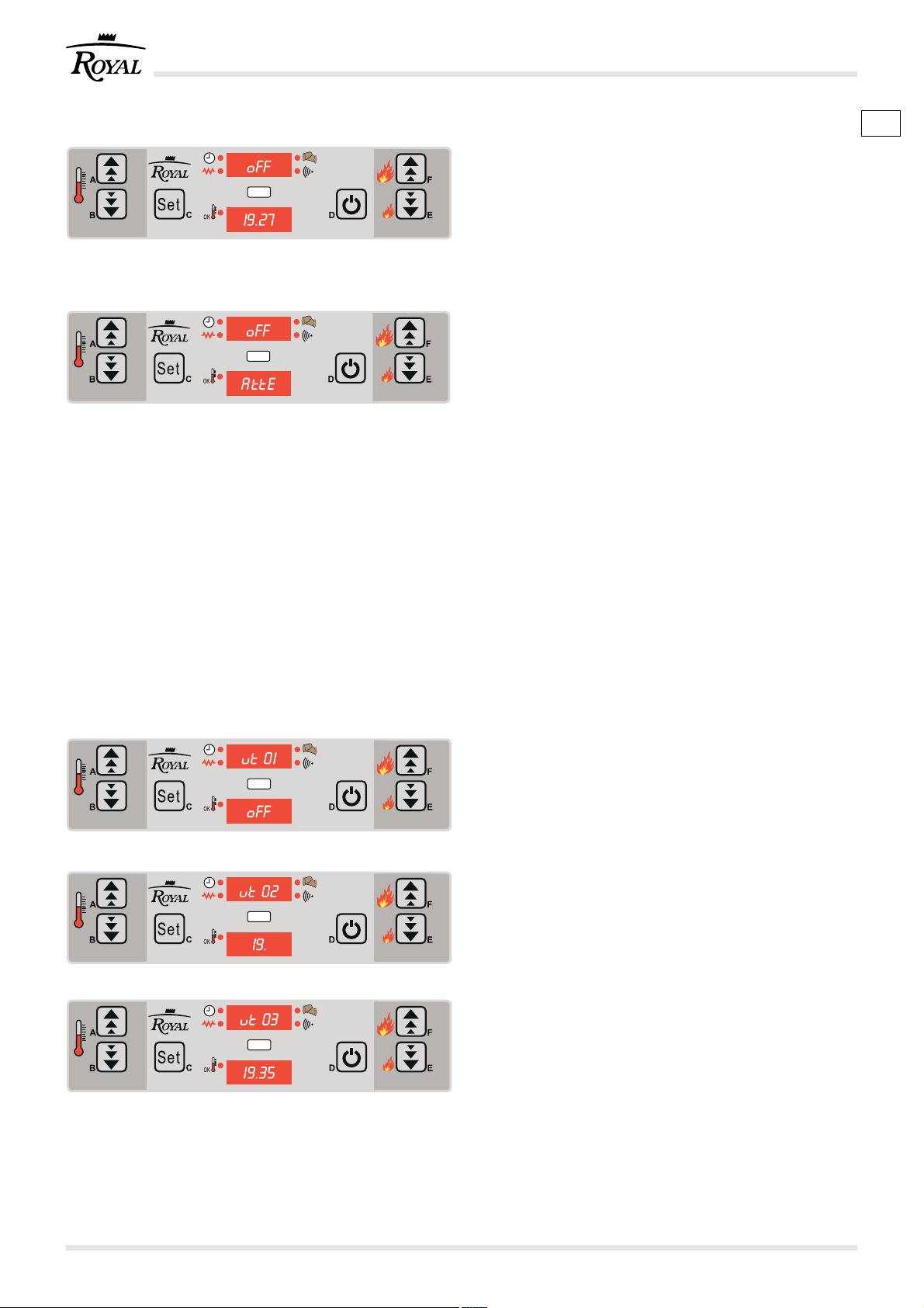
Fig. 7.5.1
Fig. 7.5.2
7.5 FASE DI SPEGNIMENTO DELLA STUFA
Per spegnere la stufa tenere premuto per alcuni
secondi il tasto On/Off (D).
Ad esempio sui display appaiono le scritte “OFF” e
“19.27”.
La coclea di caricamento dei pellet si fermerà subito
mentre il ventilatore si fermerà automaticamente a
stufa fredda.
)
Per effettuare una nuova accensione è necessario
attendere che la stufa si sia completamente
raffreddata.
Nel caso si tenti una nuova accensione a stufa non
completmente fredda
sui display appaiono le scritte “OFF” e “Atte”
che invitano l’utente ad aspettare il completo
spegnimento.
Non disconnettere la presa elettrica per spegnere
!
la stufa. Lasciare ultimare il ciclo di spegnimento. Il
funzionamento protratto del ventilatore di scarico
fumi è normale.
7.6 USO AVANZATO DEL PANNELLO COMANDO
In questo capitolo saranno illustrate e spiegate le
funzioni per la gestione avanzata della stufa, come la
programmazione dell’accensione e dello
spegnimento automatico.
IT
Fig. 7.6.1
Fig. 7.6.2
Fig. 7.6.3
1) premere il tasto menù (C);
7.6.1 Orologio
2) Selezionare “UT01” GIORNO valori compresi tra
OFF, Day1 e Day7.
3) Selezionare il giorno agendo sui tasti (A) e (B).
4) Per confermare la scelta premere il tasto menu
(C).
5) Selezionare “UT02” ORA CORRENTE valori
compresi tra 00 e 23.
6) Selezionare l’ora agendo sui tasti (A) e (B).
7) Per confermare la scelta premere il tasto menu
(C).
8) Selezionare “UT03” MINUTO CORRENTE valori
compresi tra 00 e 60.
9) Selezionare il minuto agendo sui tasti (A) e (B).
10) Per confermare la scelta premere il tasto menu
(C).
cod. 004771021 - Claudia - Ivana - Antonella - Klima 1242
Page 43

GB D
7.5 TURNING THE STOVE OFF PHASE
To turn the stove off, hold down the On/Off (D) key for
several seconds.
For example, “OFF” and “19.27” appear on the display.
The pellet loading screw stops immediately while the
fan stops automatically when the stove is cold.
)
The stove operating parameters can be set in all
three phases.
When attempting to light the stove when it has not fully
cooled “OFF” and “Atte” appear on the display to inform
the user to wait until fully off.
Do not take the plug out of the mains to turn the
!
stove off. Let the automatic turning off phase finish.
Protracted functioning of the smoke outlet fan is
normal.
7.6 ADVANCED USE OF THE CONTROL PANEL
The functions for the advanced management of the
stove will be illustrated and explained in this chapter
like, for instance, programming automatic turning on
and turning off.
1) Press the menu (C) key.
7.5 AUSSCHALTPHASE DES HEIZOFENS
Halten Sie zum Ausschalten des Heizofens die Taste
On/Off (D) einige Sekunden gedrückt.
Zum Beispiel erscheinen auf dem Display die
Meldungen “OFF” und “19.27”.
Die Beschickungsschnecke bleibt sofort stehen,
während das Gebläse automatisch bei ausgekühltem
Heizofen angehalten wird.
)
Die Betriebsparameter des Heizofens können in
allen drei Phasen eingestellt werden.
Sollte ein neuer Zündversuch bei nicht vollständig
abgekühltem Heizofen eingeleitet werden, erscheinen
auf dem Display die Meldungen “OFF” und “Atte”, die
den Anwender auffordern, die vollständige
Abschaltung abzuwarten.
Zum Ausschalten des Heizofens nicht den Stecker
!
aus der Dose ziehen. Den automatischen
Abschaltzyklus unbedingt beenden lassen. Ein länger
andauernder Betrieb des Rauchabzugventilators gilt
als normal.
7.6 ERWEITERTER GEBRAUCH DER
BEDIENBLENDE
In diesem Kapitel werden die Funktionen für die
erweiterte Heizofensteuerungen, wie die
Programmierung der Zündung und das automatische
Abschalten bzw.
1) Betätigen Sie die Taste Menü (C).
7.6.1 Clock
2) Select “UT01” DAY values include OFF, Day1 and
Day7.
3) Select the day using the (A) and (B) keys.
4) To confirm your selection, press the menu (C) key.
5) Select “UT02” CURRENT HOUR values between
00 and 23.
6) Select the hour using the (A) and (B) keys.
7) To confirm your selection, press the menu (C) key.
8) Select “UT03” CURRENT MINUTE values between
00 and 60.
9) Select the minute using the (A) and (B) keys.
10) To confirm your selection, press the menu (C) key.
7.6.1 Uhr
2) Wählen Sie “UT01” TAG mit Werten zwischen OFF,
Day1 und Day7.
3) Wählen Sie den Tag durch Betätigen der Tasten
(A) und (B).
4) Betätigen Sie zur Bestätigung der Auswahl die
Taste Menü (C).
5) Wählen Sie “UT02” AKTUELLESTUNDE mit Werten
zwischen 00 und 23.
6) Wählen Sie die Stunde durch Betätigen der Tasten
(A) und (B).
7) Betätigen Sie zur Bestätigung der Auswahl die
Taste Menü (C).
8) Wählen Sie “UT03” AKTUELLEMINUTE mit Werten
zwischen 00 und 60.
9) Wählen Sie die Minute durch Betätigen der Tasten
(A) und (B).
10) Betätigen Sie zur Bestätigung der Auswahl die
Taste Menü (C).
43cod. 004771021 - Claudia - Ivana - Antonella - Klima 12
Page 44

Fig. 7.6.4
7.6.2 Cronotermostato
Attraverso questo menù si programma l’accensione
e lo spegnimento automatico della stufa.
Per accedere ai parametri di programmazione è
indispensabile impostare il parametro “UT01” diverso
da OFF.
La funzione cronotermostato è attiva quando il
parametro “UT01” è impostato sul giorno corrente della
settimana.
Quando l’orologio è attivo si accende il LED “L”.
Le selezioni effettuate sono memorizzate
automaticamente passando al parametro successivo.
É possibile impostare quattro fasi di accensione e
spegnimento: Programma 1, Programma 2,
Programma 3 e Programma 4.
Il Programma 1 è definito dai parametri UT05 (Ora di
accensione), UT06 (ora di spegnimento), UT07 (ONOFF giorno).
Il Programma 2 è definito dai parametri UT08 (Ora di
accensione), UT09 (ora di spegnimento), UT10 (ONOFF giorno).
Il Programma 3 è definito dai parametri UT11 (Ora di
accensione), UT12 (ora di spegnimento), UT13 (ONOFF giorno).
Il Programma 4 è definito dai parametri UT14 (Ora di
accensione), UT15 (ora di spegnimento), UT16 (ONOFF giorno).
All’interno dei parametri UT05, UT06, UT08, UT09,
UT011, UT12, UT14 e UT15 agendo sui tasti (A) e (B)
si imposta l’orario aumentando o diminuiendo, con
passo di 10 minuti, l’ora che viene visualizzata sul
display inferiore (H).
I parametri UT07, UT10
I’accensione o lo spegnimento nei vari giorni.
Agendo sul tasto (A) si visualizza lo stato dei singoli
giorni.
Agendo sul tasto (B) si attiva o si disattiva il programma
del giorno da (on1/off1) a (on7/off7).
IT
, UT13, UT16 definiscono
ESEMPIO
Se voglio accendere e spegnere la stufa in questi
orari:
Lunedì 6.30 - 20.30
Martedi 5.00 - 22.00
Mercoledì 6.30 - 20.30
Giovedì 6.30 - 22.00
Venerdì 6.30 - 22.00
Sabato 8.00 - 20.00
Domenica 8.00 - 20.00
Devo impostare i parametri cosi:
UT05 6.30, UT06 20.30, UT07 (on1, off2, on3, off4,
off5, off6, off7)
UT08 5.00, UT09 22.00, UT10 (off1, on2, off3, off4,
off5, off6, off7)
UT011 6.30, UT12 22.00, UT13 (off1, off2, off3, on4,
on5, off6, off7)
UT014 8.00, UT15 20.00, UT16 (off1, off2, off3, off4,
off5, on6, on7)
cod. 004771021 - Claudia - Ivana - Antonella - Klima 1244
Page 45

7.6.2 Timer/Thermostat
GB D
This menu is used to programme automatic start-up
and shutdown of the stove.
To access programming parameters, set parameter
“UT01” to anything but OFF.
The timer/thermostat is on when the “UT01” parameter
is set to the current day of the week.
LED “L” turns on when the clock is on.
Selections are automatically saved when moving to
the next parameter.
FOUR operating programs can be set: Programme
1, Programme 2, Programme 3 and Programme 4.
Programme 1 is set using parameters UT05 (On time),
UT06 (off time), UT07 (ON-OFF day).
Programme 2 is set using parameters UT08 (On time),
UT09 (off time), UT10 (ON-OFF day).
Programme 3 is set using parameters UT11 (On time),
UT12 (off time), UT13 (ON-OFF day).
Programme 4 is set using parameters UT14 (On time),
UT15 (off time), UT16 (ON-OFF day).
In parameters UT05, UT06, UT08, UT09, UT011, UT12,
UT14 and UT15 use the (A) and (B) keys to set the
time, increasing or decreasing it by 10 minute intervals.
The time is displayed underneath (H).
Parameters UT07, UT10, UT13, UT16 set when the
stove turns on and off on the various days.
Use the (A) key to display conditions on single days.
Use key (B) to turn the day program from (on1/off1) to
(on7/off7).
EXAMPLE
To turn the stove on and off at the following times:
Monday 6.30 - 20.30
Tuesday 5.00 - 22.00
Wednesday 6.30 - 20.30
Thursday 6.30 - 22.00
Friday 6.30 - 22.00
Saturday 8.00 - 20.00
Sunday 8.00 - 20.00
Set parameters as follows:
UT05 6,30, UT06 20,30, UT07 (on1, off2, on3, off4,
off5, off6, off7)
UT08 5,00, UT09 22,00, UT10 (on1, off2, on3, off4,
off5, off6, off7)
UT011 6.30, UT12 22.00, UT13 (off1, off2, off3, on4,
on5, off6, off7)
UT014 8.00, UT15 20.00, UT16 (off1, off2, off3, off4,
off5, on6, on7)
7.6.2 Chronothermostat
In diesem Menü wird das automatische Ein- und
Ausschalten des Heizofens programmiert.
Zum Aufrufen der Programmierparameter ist es
unerlässlich, den Parameter “UT01” von OFF
verschieden einzurichten.
Die FunktionChronothermostat ist aktiv, wenn der
Parameter “UT01” auf den aktuellen Wochentag
eingerichtet ist.
Wenn die Uhr aktiv ist, schaltet sich die LED “L” ein.
Die getroffene Auswahl wird automatisch beim
Umschalten zum nächsten Parameter gespeichert.
ES ist möglich, vier Zünd- und Ausschaltphasen
einzurichten: Programm 1, Programm 2, Programm
3 und Programm 4.
Das Programm 1 wird durch die Parameter UT05
(Einschaltzeit), UT06 (Ausschaltzeit), UT07 (ON-OFF
Tag) bestimmt.
Das Programm 2 wird durch die Parameter UT08
(Einschaltzeit), UT09 (Ausschaltzeit), UT10 (ON-OFF
Tag) bestimmt.
Das Programm 3 wird durch die Parameter UT11
(Einschaltzeit), UT12 (Ausschaltzeit), UT13 (ON-OFF
Tag) bestimmt.
Das Programm 4 wird durch die Parameter UT14
(Einschaltzeit), UT15 (Ausschaltzeit), UT16 (ON-OFF
Tag) bestimmt.
Innerhalb der Parameter UT05, UT06, UT08, UT09,
UT011, UT12, UT14 und UT15 wird durch Betätigen
der Tasten (A) und (B) die Uhrzeit durch Erhöhen oder
Verringern inSchritten von 10 min eingerichtet, die auf
dem unteren Display (H) angezeigt wird.
Die Parameter UT07, UT10, UT13, UT16 legen das Ein-
oder Ausschalten an den verschiedenen Tagen fest.
Beim Betätigen der Taste (A
einzelnen Tage angezeigt.
BeimBetätigen der Taste (B) wird das Programm des
Tages von (on1/off1) bis (on7/off7) aktiviert oder
deaktiviert.
BEISPIEL
Wenn der Heizofen zu folgenden Zeiten ein- und
ausgeschaltet werden soll:
Montag 6:30 - 20:30
Dienstag 5:00 - 22:00
Mittwoch 6:30 - 20:30
Donnerstag 6:30 - 22:00
Freitag 6:30 - 22:00
Sonnabend 8:00 - 20:00
Sonntag 8:00 - 20:00
Dazu sind die Parameter wie folgt einzurichten:
UT05 6.30, UT06 20.30, UT07 (on1, off2, on3, off4,
off5, off6, off7)
UT08 5.00, UT09 22.00, UT10 (off1, on2, off3, off4,
off5, off6, off7)
UT011 6.30, UT12 22.00, UT13 (off1, off2, off3, on4,
on5, off6, off7)
UT014 8.00, UT15 20.00, UT16 (off1, off2, off3, off4,
off5, on6, on7)
) wird der Status der
45cod. 004771021 - Claudia - Ivana - Antonella - Klima 12
Page 46

Fig. 7.7.1
Fig. 7.7.1
Fig. 7.7.2
7.7 GESTIONE ALLARMI
Nel caso si verifichi un’anomalia nel funzionamento,
viene attivata la seguente procedura:
1) il caricamento dei pellet viene bloccato;
3) il ventilatore espulsione fumi viene portato alla
massima potenza.
Per poter effettuare una nuova accensione è
necessario aspettare che la stufa sia completamente
raffreddata, dopodichè si preme il tasto “D” (on/Off).
Se la stufa non è fredda si visualizza “OFF Atte”.
Di seguito sono riportati i vari messaggi di allarme
che possono apparire sul display.
7.7.1 Allarme ALAr ACC (allarme accensione)
Si verifica se la fase di accensione fallisce e si
visualizza il messaggio “ALAr ACC”.
Viene immediatamente attivata la procedura di
spegnimento.
7.7.2 Allarme CooL FirE (allarme interruzione
tensione di rete)
Si verifica se avviene una interruzione della tensione
di rete.
Al suo ripristino si visualizza il messaggio “CooL FirE”
e la stufa rimane in attesa fino a che la temperatura
fumi si riporta allo stato normale.
A questo punto viene riproposto il normale ciclo di
lavoro.
IT
Fig. 7.7.3
Fig. 7.7.4
Fig. 7.7.5
Fig. 7.7.6
7.7.3 Allarme ALar Sond (allarme sonda fumi)
Si verifica nel caso di guasto o scollegamento della
sonda per il rilevamento dei fumi.
Durante la condizione di allarme la stufa esegue la
procedura di spegnimento.
7.7.4 Allarme ALar dEP (allarme depressione)
Si manifesta nel caso in cui si verifichino le anomalie
relative a:
- tiraggio nella canna fumaria e dunque
depressione insufficiente.
Se l’allarme persiste controllare che la stufa o la canna
fumaria abbiano bisogno di manutenzione.
7.7.5 Allarme ALar PELL (allarme temperatura
pellet)
Si verifica quando la temperatura della sonda pellet è
troppo elevata.
Per ripristinare il normale funzionamento attendere
che la stufa si sia raffreddata.
7.7.6 Allarme ALar FAn (allarme ventilatore
aspirazione)
Si attiva quando si verifica un’anomalia nel
funzionamento del ventilatore fumi.
Durante la condizione di allarme la stufa esegue la
procedura di spegnimento.
cod. 004771021 - Claudia - Ivana - Antonella - Klima 1246
Page 47

7.7 ALARMS MANAGEMENT
GB D
In the case of a malfunction the following procedure is
activated:
1) Shutdown of automatic pellet loading system;
2) the smoke discharge fan works at maximum
capacity for a maximum time of twenty minutes.
To turn the stove on again, wait until it is fully cooled
and then press the key “D” (on/Off).
If the stove is not cool, “OFF Atte” is displayed.
Below are the various alarm messages that can
appear on the display.
7.7.1 Alarm ALAr ACC (ignition alarm)
This occurs when ignition fails and message “ALAr
ACC” is displayed.
The shut down procedure is immediately started.
7.7.2 Alarm CooL FirE (power outage alarm)
This occurs if there is a power outage.
When power is restored “CooL FirE” is displayed and
the stove waits until smoke temperature returns to
normal.
Normal operations can resume at this point.
7.7.3 Alarm ALar Sond (smoke probe alarm)
This occurs in the event of smoke detection probe
fault or disconnection.
The stove runs the shut down procedure during alarm
conditions.
7.7 ALARME
Bei Auftreten von Betriebsstörungen wird folgende
Prozedur eingeleitet:
1) Anhalten des automatischen Befüllsystems der
Pellets;
2) der Ventilator zur Rauchableitung wird max.
zwanzig Minuten auf Höchstleistung betrieben.
Um eine neue Zündung vornehmen zu können, ist es
notwendig, abzuwarten, dass sich der Heizofen
vollständig abgekühlt hat. Danach wird die Taste “D”
(on/Off) gedrückt.
Ist der Heizofen nicht kalt, wird “OFF Atte” angezeigt.
Anstehend die verschiedenen Alarmmeldungen, die
am Display erscheinen können.
7.7.1 Alarm ALAr ACC (Zündalarm)
Tritt auf, wenn die Zündphase fehlschlägt. Angezeigt
wird die Meldung “ALAr ACC”.
In diesem Fall wird sofort der Ausschaltvorgang
ausgelöst.
7.7.2 Alarm CooL FirE (Alarm bei Unterbrechung
der Netzspannung)
Tritt auf, wenn es zu einer Unterbrechung der
Netzspannung kommt.
Bei ihrer Wiederherstellung wird die Meldung “CooL
FirE” angezeigt und der Heizofen bleibt im Wartestatus,
bis die Rauchtemperatur wieder den normalen Wert
erreicht.
Jetzt wird der normale Betriebszyklus angeboten.
7.7.4 Alarm ALar dEP (depression alarm)
This occurs if there are anomalies concerning:
- draught in the flue pipe and hence low pressur,
insufficient.
If the alarm persists, see if the stove or flue need
servicing.
7.7.5 Alarm ALar PELL (pellet temperature alarm)
This happens when the pellet probe temperature
reaches an excessively high temperature.
To restore normal operations, wait until the stove cools.
7.7.6 Alarm ALar FAn (exhaust fan alarm)
This triggers if the smoke discharge fan is not working
properly.
The stove runs the shut down procedure during alarm
conditions.
7.7.3 Alarm ALar Sond (Alarm Rauchfühler)
Tritt imFalle eines Defekts oder eine Unterbrechung
des Rauchfühlers auf.
Während des Alarms führt der Heizofen den
Abschaltvorgang aus.
7.7.4 Alarm ALar dEP (Alarm Unterdruck)
Wird ausgelöst, wenn Störungen auftreten durch:
- Zug im Rauchfang und somit ungenügendem
Unterdruck.
Prüfen Sie, wenn der Alarm weiter vorliegt, ob der
Heizofen oder der Rauchfang gewartet werden müssen.
7.7.5 Alarm ALar PELL (Alarm Pellettemperatur)
Tritt auf, wenn die Temperatur der Pelletssonde eine
zu hohe Temperatur erreicht.
WartenSie zur Wiederherstellung des
normalenBetriebs ab, dass sich der Heizofen abkühlt.
7.7.6 Alarm ALar FAn (Alarm Ansauggebläse)
Dieser Alarm tritt bei Betriebsstörungen des
Rauchventilators auf.
Während des Alarms führt der Heizofen den
Abschaltvorgang aus.
47cod. 004771021 - Claudia - Ivana - Antonella - Klima 12
Page 48

7.7.7 Allarme ALar hot (allarme sovra temperatura
fumi)
Si manifesta quando la sonda fumi rileva una
temperatura troppo elevata.
IT
A
Fig. 7.7.7
Fig. 7.7.8
Fig. 7.7.9
Fig. 7.8.1
B
7.7.8 Allarme ALar FirE (allarme spegnimento
durante la fase di lavoro)
Si manifesta durante la fase di lavoro se la fiamma si
spegne e la temperatura fumi scende al di sotto della
soglia minima di funzionamento.
È immediatamente attivata la procedura si
spegnimento.
7.7.9 Allarme ALar Sic (allarme termostato
generale)
Si manifesta se il termostato di sicurezza generale
rilevi una temperatura superiore a quella consentita.
Si visualizza il messaggio “ALar Sic” e il sistema viene
arrestato.
7.8 PULIZIA BRACIERE
Può accadere che durante la normale operatività nella
modalità lavoro, a intervalli stabiliti, viene attivata la
modalità “PULIZIA BRACIERE”.
Si visualizza il messaggio “StoP FirE”.
7.9 CANALIZZAZIONE DELL’ARIA
(solo per i modelli canalizzabili o provvisti di kit di
canalizzazione)
Le stufe Ecofire canalizzabili o dotate di kit di
canalizzazione hanno la possibilità di essere
configurate in modo da deviare l’aria calda su due
canalizzazioni diverse.
Una è quella di riscaldamento della stanza in cui è
posizionata la stufa Fig.7.9.1 (A) attraverso le griglie
frontali o superiori (in base al modello). L’altra è quella
che permette di riscaldare anche ambienti distanti
dalla stufa Fig.7.9.1 (B) predisponendo un impianto
di canalizzazione dell’aria.
Per deviare il flusso dell’aria calda (completamente o
parzialmente) da una parte o dall’altra utilizzare
l’apposito utensile in dotazione con la stufa e agire
sul comando posto tra le griglie frontali.
Fig. 7.9.1
cod. 004771021 - Claudia - Ivana - Antonella - Klima 1248
Page 49

7.7.7 Alarm ALar hot (smoke over temperature
GB D
alarm)
This occurs when the smoke probe detects too high
temperature.
7.7.7 Alarm ALar hot (Alarm
Rauchübertemperatur)
Tritt auf, wenn der Rauchfühler eine zu hohe
Temperatur ermittelt.
7.7.8 Alarm ALar FirE (shut down during
operations alarm)
This occurs during operations if the flame goes out
and the smoke temperature drops under the minimum
operating threshold.
The shut down procedure is immediately initiated.
7.7.9Alarm ALar Sic (main thermostat alarm)
This occurs if the main safety thermostat reads a
temperature over the permitted one.
Message “ALar Sic” is displayed and the system is
stopped.
7.8 CLEAN GRATE
“CLEAN GRATE” mode may be activated, at set
intervals, during normal operations.
Message “StoP FirE” is displayed.
7.9 AIR DUCTS
(only for ducted models or provided with ducting kit)
Ducted Ecofire stoves or fitted with ducting kit can be
configured to deviate the hot air produced to two
different outlets.
One is for heating the room where the stove is installed,
Fig.7.9.1 (A) through the front or top grills (according
to the model). The other is used to heat other rooms
away from the stove, Fig.7.9.1 (B), through a system of
air ducts.
To deviate the flow of hot air (completely or partially)
from one outlet to the other, use the special tool
supplied with the stove and adjust the control placed
between the front grills.
7.7.8 Alarm ALar FirE (Abschaltalarm während der
Betriebsphase)
Tritt während der Betriebsphase auf, wenn die
Flamme verlischt und die Rauchtemperatur unter die
minimale Betriebsgrenze sinkt.
Dabei wird unverzüglich der Ausschaltvorgang
eingeleitet.
7.7.9 Alarm ALar Sic (Alarm Hauptthermostat)
Tritt auf, wenn das Sicherheitsthermostat eine höhere
Temperatur als zulässig ermittelt.
Es erscheint die Meldung “ALar Sic” und das System
wird angehalten.
7.8 REINIGUNG DES GLUTBECKENS
Es kann dazu kommen, dass während des normalen
Betriebs im Betriebsmodus in festgelegten Abständen
der Modus “REINIGUNGGLUTBECKEN” ausgelöst
wird.
Es wird die Meldung “StoP FirE” angezeigt.
7.9 LUFTKANALISIERUNG
(nur für kanalisierbare Modelle bzw. Modelle mit
Kanalisierungsset)
Die kanalisierbaren oder mit Kanalisierungsset
ausgestatteten Öfen Ecofire können so konfiguriert
werden, dass die Warmluft zu zwei verschiedenen
Kanalisierungen geleitet wird.
Eine ist die Kanalisierung, mit der der
Aufstellungsraum des Ofens über die (je nach Modell)
frontseitig oder oben befindlichen Gitter geheizt wird,
siehe Abb. 7.9.1 (A) Die andere ist die Kanalisierung,
mit der auch entfernte Räume geheizt werden können,
siehe Abb. 7.9.1 (B). Hierzu ist ein Luftleitsystem
anzulegen.
Um den Warmluftstrom (ganz oder teilweise) von
einem Ort zum anderen umzuleiten, muss mit dem
Werkzeug, das dem Ofen beiliegt, die Umsteuerung
zwischen den frontseitigen Gittern verstellt werden.
49cod. 004771021 - Claudia - Ivana - Antonella - Klima 12
Page 50

8 MANUTENZIONE E PULIZIA
8.1 PRECAUZIONI DI SICUREZZA
Prima di effettuare qualsiasi operazione di
!
manutenzione adottare le seguenti precauzioni:
A) Assicurarsi che tutte le parti della stufa siano
fredde.
B) Accertarsi che le ceneri siano completamente
spente.
C) Utilizzare i dispositivi di protezione individuale
previsti dalla direttiva 89/391/CEE.
D) Accertarsi che l'interruttore generale di linea sia
disinserito.
E) Accertarsi che l’alimentazione non possa essere
riattivata accidentalmente. Staccare la spina dalla
presa a muro.
F) Operare sempre con attrezzature appropriate per
la manutenzione.
G) Terminata la manutenzione o le operazioni di
riparazione, prima di rimettere la stufa in servizio,
reinstallare tutte le protezioni e riattivare tutti i
dispositivi di sicurezza.
IT
8.2 MANUTENZIONE ORDINARIA RIVOLTA
ALL’UTILIZZATORE
8.2.1 Pulizia interna del focolare
La stufa necessita di una semplice ma frequente ed
accurata pulizia per poter garantire sempre un
efficiente rendimento ed un regolare funzionamento.
Eseguire la pulizia con l’apparecchiatura fredda.
PULIZIA GIORNALIERA.
Asportare la cenere che si deposita all’interno del
focolare. (Fig. 8.2.1)
Questa pulizia ha lo scopo di assicurare il libero
afflusso dell’aria di combustione dai fori del
BRACIERE.
L’uso di un aspirapolvere può semplificare la pulizia
delle ceneri.
Utilizzare aspirapolvere adatti tipo “bidone”, dotati di
filtro a maglie fini per evitare di:
- riversare in ambiente parte delle ceneri aspirate;
- danneggiare l'aspirapolvere stesso.per
aspirazione di particelle di una certa dimensione).
Fig. 8.2.1
cod. 004771021 - Claudia - Ivana - Antonella - Klima 1250
Page 51

GB D
8 MAINTENANCE AND CLEANING
8 INSTANDHALTUNG UND REINIGUNG
8.1 SAFETY PRECAUTIONS
Prior to embarking on any maintenance work the
!
following precautions must be taken:
A) Make sure all parts of the stove are cold.
B) Make sure the ashes are completely cold and not
burning.
C) Use the individual protective gear as established
by the EEC directive 89/391.
D) Check that the main line switch is off.
E) Make sure the power supply cannot be switched
on accidentally. Take the plug out of the wall socket.
F) Always use the most appropriate maintenance
tools.
G) Once the maintenance or repair work is finished
reinstall all the protections and reactivate all the
safety devices before turning the stove back on.
8.2 ROUTINE MAINTENANCE FOR THE USER
8.2.1 Cleaning the inside of the firebox
The stove requires a simple but frequent and thorough
clean to guarantee it will work properly and to ensure
constant heat efficiency.
Clean only when the stove is cold.
8.1 VORBEUGENDE SICHERHEITSMASSNAHMEN
Vor jedem Wartungseingriff unbedingt folgende
!
Sicherheitsmaßnahmen treffen:
A) Sicherstellen, dass alle Heizofenteile kalt sind.
B) Sicherstellen, dass die Asche komplett erloschen
ist.
C) Die laut Richtlinie 89/391/EWG vorgesehenen
individuellen Schutzvorrichtungen anwenden.
D) Sicherstellen, dass der Hauptschalter
ausgeschaltet ist.
E) Sicherstellen, dass die Stromversorgung nicht
ungewollt wieder hergestellt werden kann. Den
Stecker aus der Dose ziehen.
F) Für die Wartung immer geeignetes Werkzeug
verwenden.
G) Nach den Wartungs- oder Reparaturarbeiten
wieder alle Abdeckungen installieren und
Schutzvorrichtungen aktivieren, bevor der Heizofen
wieder in Betrieb genommen wird.
8.2 REGELMÄSSIGE INSTANDHALTUNG (FÜR
DEN BENUTZER)
8.2.1 Interne Reinigung der Feuerstelle
Der Heizofen benötigt nur eine einfache
Instandhaltung, die aber häufig und sorgfältig
durchzuführen ist, um eine effiziente Leistung und
einen ungestörten Betrieb zu gewährleisten.
DAILY CLEANING.
Remove the ask from the inside the firebox. (Fig. 8.2.1)
By throwing away the ashes every day the air for
combustionxwill flow freely through the holes in the
HEARTH.
Use a suitable type of vacuum cleaner, fitted with a
fine mesh filter to prevent:
- any of the ash dirtying the room;
- damaging the vacuum cleaner.
Die Reinigung bei kaltem Gerät durchführen.
TÄGLICHE REINIGUNG.
Die Asche, die sich innerhalb der Feuerstelle und im
Aschenkasten ablagert (Abb. 8.2.1), jeden Tag bzw.
wenn nötig entfernen; dazu einen Metallbehälter
verwenden.
Der Einsatz eines Staubsaugers kann die Reinigung
vereinfachen.
Nur geeignete Staubsauger mit feinem Filter
verwenden, um zu vermeiden, dass:
- ein Teil der angesaugten Asche wieder in den
Raum gelangt;
- der Staubsauger selbst beschädigt wird.
51cod. 004771021 - Claudia - Ivana - Antonella - Klima 12
Page 52

Fig. 8.2.2
IT
PERIODICAMENTE
Eseguire periodicamente una pulizia completa della
CALDAIA rimuovendo a freddo lo schienale di fondo
in ghisa.
Per estrarre lo schienale procedere come segue:
1) estrarre il braciere (Fig. 8.2.2);
2) far presa sull'asola presente nella parte
superiore;
3) sollevare la ghisa in modo che esca dagli appositi
incastri posti nella parte inferiore;
4) inclinare la parte inferiore della ghisa verso la
portina ed estrarla completamente. (Fig. 8.2.3 e
8.2.4).
Fig. 8.2.3
)
La presenza di condensa è indice di eventuali
infiltrazioni di acqua o di raffreddamento eccessivo
dei fumi. Si consiglia di individuare le possibili cause
per ripristinare il corretto funzionamento del
prodotto.
Fig. 8.2.4
cod. 004771021 - Claudia - Ivana - Antonella - Klima 1252
Page 53

GB D
)
PERIODICALLY
Clean the BOILER thoroughly, removing the back cast
iron panel when it is cold.
To remove the back panel, proceed as follows:
1) pull the hearth out (Fig. 8.2.2);
2) grip and lever on the slot at the top;
3) lift the cast iron panel so it slips out of the slots at
the bottom;
4) slant the bottom of the cast iron panel towards
the door and pull it right out. (Figs. 8.2.3 and 8.2.4)
Condensation means water is seeping in or the
smoke is being cooled excessively. Find the cause(s)
and restore correct operation of the stove.
)
REGELMÄSSIGE REINIGUNG
Der KESSEL ist in regelmäßigen Zeitabständen
vollständig zu reinigen, dazu ist die Rückwand aus
Gusseisen nach ihrem Erkalten zu entfernen.
Zur Entfernung der Rückwand wie folgt vorgehen:
1) das Feuerbecken herausziehen (Abb. 8.2.2);
2) das Feuerbecken über die Öffnung im oberen
Bereich anheben;
3) die Gusseisenplatte anheben und aus den
Steckvorrichtungen im hinteren Bereich lösen;
4) die Gusseisenplatte unten zur Tür hin neigen und
komplett herausziehen. (Abb. 8.2.3 und 8.2.4).
Das Auftreten von Kondenswasser bedeutet, dass
entweder Wasser eindringt oder der Rauch zu stark
abkühlt. Die möglichen Ursachen ausfindig machen
und den Betrieb wieder korrekt herstellen.
53cod. 004771021 - Claudia - Ivana - Antonella - Klima 12
Page 54

Fig. 8.2.5
8.2.2 Pulizia del cassetto cenere
(per i modelli provvisti di cassetto cenere)
La pulizia del cassetto cenere va eseguita ogni
settimana o quando necessario.
Per accedere al cassetto cenere, aprire la porta
cassetto cenere ed estrarre il cassetto (Fig.15.4) con
lo strumento in dotazione. Svuotare il cassetto.
Aspirare le eventuali ceneri residue dal vano che
ospita il cassetto cenere. Reinserire e richiudere il
cassetto. Richiudere le porte.
8.2.2.1 Pulizia del vano raccogli cenere
(per i modelli dotati di vano raccogli cenere)
La pulizia del cassetto cenere va eseguita ogni
settimana o quando necessario.
Aprire la portina del focolare e aspirare con un apposito
aspiracenere l’accumulo di cenere depositatosi nel
vano raccogli cenere lateralmente al braciere
(Fig.15.5).
8.2.3 Pulizia del vetro
Si effettua con un panno umido o con della carta
inumidita e passata nella cenere.
Strofinare finchè il vetro è pulito.
Si possono anche usare dei detergenti adatti per la
pulizia dei forni da cucina.
Non pulire il vetro durante il funzionamento della stufa
e non utilizzare spugne abrasive.
Non inumidire la guarnizione della portina perchè
potrebbe deteriorarsi.
IT
Fig. 8.2.5
8.2.4 Pulizia della canna fumaria
Da effettuarsi almeno due volte all’anno, inizio e metà
stagione invernale, e comunque ogni volta sia
necessario.
Se esistono dei tratti orizzontali, é necessario verificare
e asportare l’eventuale deposito di cenere e fuliggine
prima che le stesse otturino il passaggio dei fumi.
In caso di mancata o inadeguata pulizia la stufa può
avere problemi di funzionalità quali:
- cattiva combustione;
- annerimento del vetro;
- intasamento del braciere con accumulo di ceneri
e pellet;
- deposito di ceneri ed eccessive incrostazioni sullo
scambiatore con conseguente scarso
rendimento.
A) Comigolo antivento (Fig. 8.2.6).
B) Ispezione. (Fig. 8.2.6).
Fig. 8.2.6
cod. 004771021 - Claudia - Ivana - Antonella - Klima 1254
Page 55

8.2.2 Cleaning the ash box
GB D
(for models fitted with ash bin)
The ash bin should be cleaned every week or
whenever necessary.
To access the ash bin, open the ash bin door and
remove the bin (Fig.15.4) using the tool provided. Empty
the bin. Vacuum any residual ash from the
compartment that houses the ash bin. Reposition and
close the ash bin. Close the doors.
8.2.2.1 Cleaning the ash compartment
(for models fitted with ash compartment)
The ash compartment should be cleaned every week
or whenever necessary.
Open the firebox door and use a special ash vacuum
cleaner to remove the ash accumulated in the ash
compartment next to the burn pot (Fig.15.5).
8.2.3 Cleaning the glass
Clean the glass with a damp cloth or damp paper
rubbed in ashes.
Rub the glass until it comes clean.
You can also use ordinary oven cleaners.
Do not clean the glass while the stove is working and
do not use abrasive sponges.
8.2.4 Cleaning the flue
The flue should be cleaned at least twice a year at the
beginning and half way through the winter season
and any other time it is necessary.
If there are any horizontal sections you must check
and remove any ash or soot that may have deposited
before they have the chance to close the smoke
passage.
Failure to clean or clean thoroughly will probably lead
to stove operating problems, such as:
- bad combustion;
- blackening of the glass;
- clogging of the hearth with an accumulation of
ash and pellets;
- deposit of ash and encrustation on the exchanger
leading to poor heat efficiency.
A) Windproof chimney top (Fig. 8.2.6).
B) Inspection. (Fig. 8.2.6).
8.2.2 Reinigung der Aschenlade
(Modelle mit Aschekasten)
Die Reinigung des Aschekastens ist einmal
wöchentlich oder bei Bedarf durchzuführen.
Um den Aschekasten freizulegen, die Tür des
Aschekastens öffnen und den Aschekasten mithilfe
des mitgelieferten Werkzeugs herausziehen (Abb.
15.4). Den Aschekasten entleeren. Eventuell in der
Aufnahme des Aschekastens verbliebene
Ascherückstände entfernen. Den Kasten wieder
einschieben und schließen. Die Türen wieder
schließen.
8.2.2.1 Reinigung des aschefachs
(Modelle mit Aschefach)
Die Reinigung des Aschefachs ist einmal wöchentlich
oder bei Bedarf durchzuführen.
Die Tür des Feuerraums öffnen und mit einem
Aschesauger die Asche, die sich in dem Aschefach
neben der Brennschale angesammelt hat, absaugen
(Abb. 15.5).
8.2.3 Reinigung des Glases
Die Glasscheibe mit einem feuchten Lappen oder mit
zusammengeballtem, in Asche gewälztem
Zeitungspapier reinigen.
Solange reiben, bis das Glas sauber ist.
Es können auch Reinigungsmittel verwendet werden,
die für das Säubern von Küchenherden geeignet sind.
Die Glasscheibe nicht bei betriebenem Heizofen
reinigen und keine Scheuerlappen verwenden.
Die Türdichtung nicht feucht machen, da sie sich
verbiegen kann.
8.2.4 Reinigung des Rauchfangs
Der Rauchfang ist mindestens zweimal jährlich zu
reinigen - Anfang und Mitte der Wintersaison
Bei waagrechten Rauchfangleitungen sind eventuelle
Aschen- und Russablagerungen zu entfernen, bevor
sie die Leitung verstopfen.
Bei fehlender oder unzureichender Reinigung kann der
Heizofen folgende Betriebsstörungen aufweisen:
- Schlechte Verbrennung;
- Schwarzwerden der Glasscheibe;
- Verstopfung des Kohlenbeckens durch Aschenund Pelletsansammlung;
- Aschenablagerung und Verkrustungen am
Austauscher mit folgendem Leistungsrückgang.
A) Windschutzkamin (Abb. 8.2.6).
B) Inspektion (Abb. 8.2.6).
55cod. 004771021 - Claudia - Ivana - Antonella - Klima 12
Page 56

C
A
B
8.2.5 Regolazione della Maniglia
La maniglia della portina è regolata già dalla fabbrica
per una chiusura ottimale.
Dopo alcune settimane di utilizzo, in seguito al normale
assestamento delle guarnizioni di tenuta, può rendersi
necessaria una regolazione della maniglia per
ripristinare la perfetta chiusura della portina.
Si dovrà agire in questo modo (Fig. 8.2.7):
- allentare la vite di fissaggio (A) (chiave esagono
incassato 2 mm).
- ruotare il perno di rotazione (C) (utilizzando una
chiave da 15) fino a compensare il gioco causato
dall’assestamento della guarnizione.
- Una volta ottenuta una giusta regolazione del
perno, riavvitare saldamente la vite (A).
- Agendo sulla vite (B) (chiave esagono incassato
da 3,5 mm.) potremo regolare la tensione della
maniglia rendendo più o meno facile la sua
rotazione sul perno. (Questa regolazione si
ottiene dopo aver allentato la vite “A”).
8.3 MANUTENZIONE STRAORDINARIA
La stufa è un generatore di calore a combustibile
solido e come tale necessità di un intervento annuale
di manutenzione straordinaria che deve essere
effettuato dal Centro di Assistenza Tecnica Autorizzato
della Royal una volta all’anno e preferibilmente a inizio
stagione.
Questa manutenzione ha lo scopo di accertare ed
assicurare la perfetta efficienza di tutti i componenti.
)
Si consiglia di concordare con il centro di Assistenza
Tecnica Autorizzato, un contratto annuale di
manutenzione del prodotto.
IT
Fig. 8.2.7
cod. 004771021 - Claudia - Ivana - Antonella - Klima 1256
Page 57

8.2.5 Adjusting the handle
GB D
The handle on the door is already factory-set for
optimum closing. After a few weeks of use and normal
settling of the seals, the handle might need adjusting
to ensure perfect closing of the door.
In such an event proceed as follows:
- loosen the securing screw (A) (with a 2mm Allen
wrench).
- turn the rotation pin (C) (using a size 15 spanner)
until there is no play caused by settling of the seal.
- once the pin is adjusted correctly, tighten the screw
firmly (A).
- by turning screw (B) (with a 3.5 mm Allen wrench)
adjust handle tension, so it turns to the right extent
on the pin. (For this adjustment you first have to
loosen screw "A").
8.2.5 Griffeinstellung
Der Türgriff wird werkseitig für ein optimales
Schließen eingestellt.
Nach einigen Betriebswochen kann aufgrund einer
normalen Setzung der Dichtungen die Notwendigkeit
bestehen, den Griff für den einwandfreien Türverschluss
einzustellen.
Wie folgt vorgehen (Abb. 8.2.7):
- die Schraube (A) lockern (2-mm-Inbusschlüssel)
- den Zapfen (C) mit einem 15er-Schlüssel so
drehen, dass das durch die Setzung der Dichtung
entstandene Spiel ausgeglichen wird.
- nach der richtigen Einstellung des Zapfens die
Schraube (A) wieder gut festschrauben.
- über die Schraube (B) (3,5-mm-Inbusschlüssel)
kann die Griffdrehung am Zapfen eingestellt
werden. (für diese Regelung zuerst die Schraube
„A“ lockern).
8.3 EXTRAORDINARY MAINTENANCE
8.3 AUSSERORDENTLICHE WARTUNG
Der Heizofen ist ein Heizgenerator für die Beschickung
mit festen Brennstoffen und benötigt dadurch eine
jährliche außerordentliche Wartung, die am Besten am
Anfang der Heizsaison von einer autorisierten RoyalKundendienststelle durchgeführt werden sollte.
Diese Wartung überprüft und gewährleistet die
perfekte Leistungsfähigkeit aller eingesetzten
Bestandteile.
)
Es wird empfohlen, mit einer autorisierten
Kundendienststelle einen jährlichen
Wartungsvertrag abzuschließen.
)
The stove is a heat generator that uses solid fuel and
therefore requires annual extraordinary maintenance
that has to be done by an authorised Royal Technical
Assistance Centre either once a year or preferably at
the beginning of the season.
The reason for this maintenance is to ascertain and
ensure the perfect efficiency of all the components.
We recommend drawing up an annual maintenance
contract for the product with the Authorised
Technical Assistance Centre.
57cod. 004771021 - Claudia - Ivana - Antonella - Klima 12
Page 58

9 INFORMAZIONI PER LA
DEMOLIZIONE E LO SMALTIMENTO
La demolizione e lo smaltimento della stufa sono ad
esclusivo carico e responsabilità del proprietario che
dovrà agire in osservanza delle leggi vigenti nel proprio
Paese in materia di sicurezza, rispetto e tutela
dell’ambiente.
Smantellamento e smaltimento possono essere
affidati anche a terzi, purchè si ricorra sempre a ditte
autorizzate al recupero ed all'eliminazione dei
materiali in questione.
IT
)
!
!
INDICAZIONE: attenersi sempre e comunque alle
normative in vigore nel Paese dove
si opera per lo smaltimento dei
materiali ed eventualmente per la
denuncia di smaltimento.
ATTENZIONE: Tutte le operazioni di smontaggio per
la demolizione devono avvenire a
stufa ferma e privata dell’energia
elettrica di alimentazione.
- asportare tutto l’apparato elettrico;
- separare gli accumulatori presenti
nelle schede elettroniche;
- rottamare la struttura della stufa
tramite le ditte autorizzate;
ATTENZIONE: L'abbandono della stufa in aree
accessibili costituisce un grave
pericolo per persone ed animali.
La responsabilità per eventuali danni
a persone ed animali ricade sempre
sul proprietario.
All’atto della demolizione la marcatura CE, il presente
manuale e gli altri documenti relativi a questa stufa
dovranno essere distrutti.
cod. 004771021 - Claudia - Ivana - Antonella - Klima 1258
Page 59

GB D
9 INFORMATION FOR DEMOLITION
AND DISPOSAL
9 INFORMATIONEN FÜR DEN ABRISS
UND DIE ENTSORGUNG
)
!
!
Demolition and disposal is the sole responsibility of
the owner who must comply with the relative laws in
force in his country on the matter of safety and
safeguarding the environment.
Dismantling and disposal may be entrusted to a third
party provided we are talking about a company
authorised to salvage and eliminate said materials.
INDICATION: in all cases you must abide by the
laws in force in the country of
installation as regards the disposal of
materials and, if necessary, the report
of disposal.
ATTENTION: all dismantling operations for
demolition must be carried out when
the stove is not working and not
electrically powered.
- remove all the electrical parts;
- separate the storage batteries from
the electronic cards;
- scrap the stove's structure by way of
authorised companies;
ATTENTION: dumping the stove in accessible areas
is a serious hazard for both people
and animals.
The responsibility for harm caused to
people or animalsis always on the
shoulders of the owner.
When the stove is demolished, the CE mark, this
manual and other documents concerning this stove,
must be destroyed.
)
!
!
Der Abriss und die Entsorgung des Heizofens geht
ganz und gar zu Lasten des Eigentümers, der auch
dafür verantwortlich ist und gemäß den gültigen
Sicherheits- und Umweltschutzvorschriften des
Aufstellungslands vorzugehen hat.
Mit dem Abriss und der Entsorgung können auch
Firmen beauftragt werden, die für die Sammlung und
Entsorgung der betroffenen Materialien befugt sind.
HINWEIS: Immer die einschlägigen Normen
des jeweiligen Lands für die
Entsorgung und eventuelle
Entsorgungsmeldung einhalten.
ACHTUNG: Alle zum Abriss nötigen
Zerlegungsarbeiten müssen bei
stillstehendem Gerät und
unterbrochener Stromzufuhr
vorgenommen werden.
- die ganze Elektroanlage
abnehmen;
- die Batterien aus den
Elektronikkarten nehmen;
- die Gerätestruktur über befugte
Unternehmen verschrotten;
ACHTUNG: Die Verwahrlosung des Geräts an
zugänglichen Stellen stellt eine große
Gefahr für Personen und Tiere dar.
Die Verantwortung für eventuelle
Schäden an Personen und Tieren
trägt immer der Eigentümer.
Beim Abriss müssen das CE-Markenzeichen, dieses
Handbuch und alle Unterlagen zu diesem Gerät
vernichtet werden.
59cod. 004771021 - Claudia - Ivana - Antonella - Klima 12
Page 60
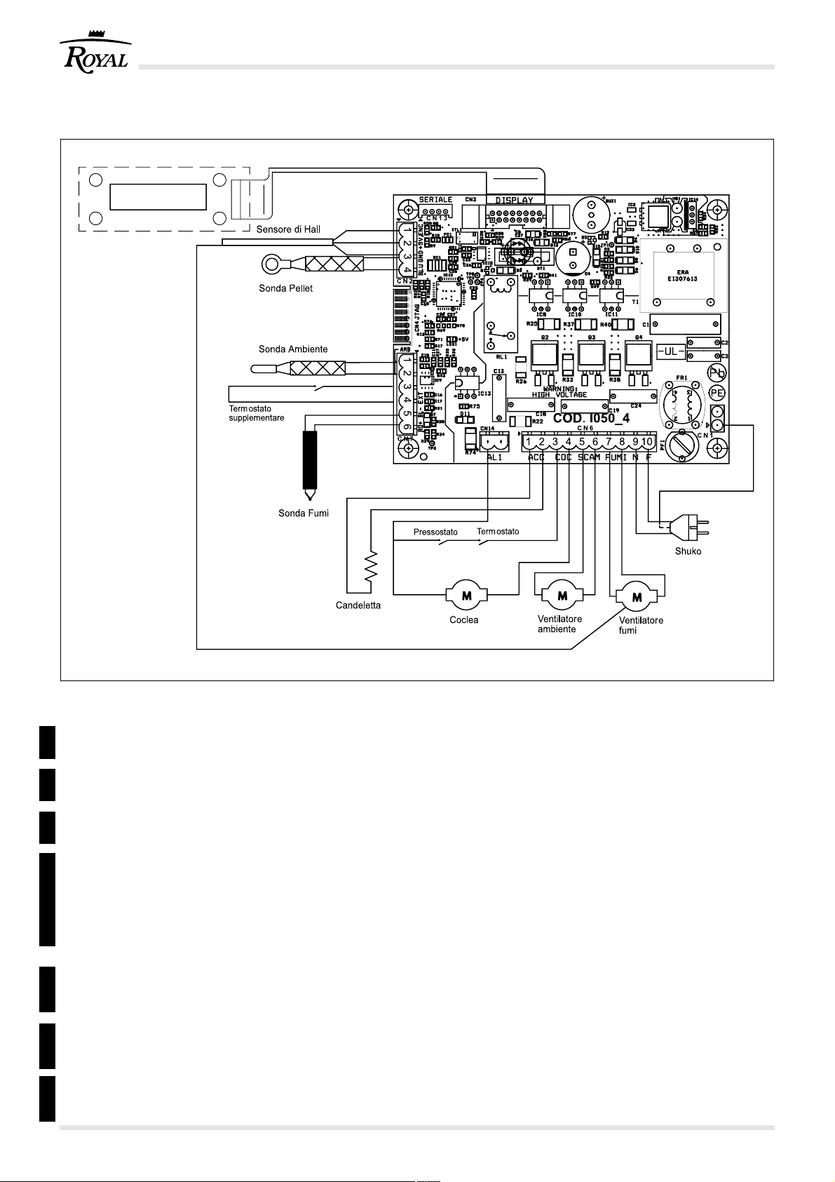
10 SCHEMA ELETTRICO - WIRING DIAGRAM - ELEKTRISCHER SCHALTPLAN
Pannello di controllo
SCHEMA ASSEMBLAGGIO ELETTRICO
....... MASSA ALIMENTAZIONE
....... SENSORE DI HALL (1) (2) (3)
....... SONDA PELLET (3) (4)
CN2CN3CN6CN7CN14
....... PANNELLO COMANDI
....... RESISTENZA AD INCANDESCENZA (1) (2)
....... DOSATORE CARICAMENTO (3) (4)
....... TERMOSTATO (3)
....... VENTILATORE SCARICO FUMI (7) (8)
....... VENTILATORE AMBIENTE (5) (6)
....... ALIMENTAZIONE 230 V 50 Hz (9) (10)
....... SONDA FUMI (5) Rosso (+) - (6) Blu (-)
....... TERMOSTATO AMBIENTE (3) (4)
....... SONDA AMBIENTE (1) (2)
....... USCITA SERIALE
CN13 CN1
....... PRESSOSTATO
WIRING DIAGRAM
....... GROND
....... EXHAUST FAN SPEED SENSOR (1) (2) (3)
....... PELLET PROBE (3) (4)
....... DISPLAY
....... IGNITER (1) (2)
....... FEEDING SYSTEM (3) (4)
....... THERMOSTAT (3)
....... EXHAUST FAN (7) (8)
....... ROOM FAN (5) (6)
....... SUPPLY 230 V 50 Hz (9) (10)
....... SMOKE PROBE (5) Red (+) - (6) Blue (-)
....... ROOM THERMOSTAT (3) (4)
....... ROOM PROBE (1) (2)
....... SERIAL PORT
....... VACUUM SWITCH
cod. 004771021 - Claudia - Ivana - Antonella - Klima 1260
Page 61
ELEKTRISCHES MONTAGESCHEMA
....... MASSE
....... HALL FUEHLER (1) (2) (3)
.......
PELLETSONDE (3) (4)
....... STEUERPANEEL
....... GLUTFEST (1) (2)
....... SPENDER (3) (4)
....... RAUMTEMPERATURREGLER (3)
....... ABGASVENTILATOR (7) (8)
....... RAUMLUFTGEBLAESE (5) (6)
....... VERSORGUNG 230 V 50 Hz (9) (10)
....... RAUCHSONDE (5) Rot (+) - (6) Blau (-)
....... RAUMTEMPERATURREGLER (3) (4)
....... RAUMSONDE (1) (2)
....... SERIENAUSGANG
CN13 CN1CN2CN3CN6CN7CN14
....... DRUCKWAECHTER
61cod. 004771021 - Claudia - Ivana - Antonella - Klima 12
Page 62

) a
2
) a
2
) à (ref. 13% O
2
) (réf 13% O
2
) à (ref. 13% O
) (réf 13% O
) puissance nominale potencia nominal
) Teillast (13% O
2
2
puissance partielle potencia parcial
2
2
) heat output (13% O
2
LEGEND ETIQUETTE PRODUIT – LEYENDA PLACA DE CARACTERISTÍCAS
all’ambiente heat output Raumnennwärmeleistung a l’aìr a la aìre
all’ambiente heat output a l’aìr a la aìre
all’acqua to water Nennwärmeleistung à l’eau al agua
all’acqua to water Teilwärmeleistung à l’eau al agua
di esercizio waterpressure Betriebsdruck d’utilisation de utilizaciòn
nominale heat output Nennwärmel puissance nominale potencia nominal
potenza ridotta heat output puissance partielle potencia parcial
) heat output (13% O
2
nominale (13% O
materiali infiammabili and combustible materials brennbaren Bauteilen mind. matériaux inflammables materiales inflammables
in funzionamento absorbed when working Leistung (Betrieb) utilisée en phase de travail en fase de trabajo
in accensione absorbed for ignition Leistung (Zündung) en phase d’allumage en fase de arranque
L’apparecchio non può The appliance cannot be Ofen kann nicht mit andere L’appareil ne peut pas Être No se puede utilizàr
LEGENDA TARGHETTA MATRICOLA – LEGEND PRODUCT LABEL – BESCHREIBUNG TYPENSCHILD
SIMBOLOGIA ITALIANO ENGLISH DEUTSCH FRANCAIS ESPAÑOL
F Combustibile Fuel type Brennstoff Combustible Combustible
Pmax Potenza termica nominale Nominal space Max. Puissance nominale Potencia nominal
Pmin Potenza termica ridotta Reduced space Raumteilwärmeleistung Puissance partielle Potencia parcial
Pwmax Potenza nominale Nominal heat output Wasserseitig Max. Puissance nominale Potencia nominal
p Pressione massima Maximum operating Maximaler Pression maximale Presìon màxima
Pwmin Potenza ridotta Reduced heat output Wasserseitig Puissance partielle Potencia parcial
EFFmin Rendimento alla Efficiency at reduced Wirkungsgrad Teillast Rendement à Rendimiento a
EFFmax Rendimento alla Efficiency at nominal Wirkungsgrad Rendement à Rendimiento a
) alla potenza at nominal Nennwärmel (13% O
2
COmax Emissioni di CO CO emmissions Emissionen bei CO Emissions de CO Emisiones de CO
(13% O
) potenza ridotta (13% O
2
d Distanza minima da Distance between sides Mindestabstand zu Distance minimum avec. Distancia mínima con
COmin Emissioni di CO alla CO emmissions at partial Emissionen bei CO Emissions de CO Emisiones de CO
(13% O
V Tensione Voltage Spannung Tension Tensión
cod. 004771021 - Claudia - Ivana - Antonella - Klima 1262
f Frequenza Frequency Frequenz Fréquence Frecuencia
Wmin Potenza Max assorbita Maximum power Max. aufgenommene Puissance maximale Potencia máxima utilizada
Wmax Potenza Max assorbita Maximum power Max. aufgenommene Puissance maximale utilisée Potencia máxima utilizada
canna fumaria condivisa Kamin funktionieren partagé avec autres appareils canòn compartido
essere utilizzato in una used in a shared flue in ein gemeinsames utilisé dans un conduit el aparato en
Usare solo il combustibile Use only Brennstoff verwenden Nur Utiliser seulement les Utilizen solamente
raccomandato recommended fuel den vorgeschriebenen combustibles prescrites combustibles otorgados
L’apparecchio funziona a The appliance is capable Der ofen ist ein L’appareil fonctionne à El aparato funciòna a
Leggere e seguire le istruzioni Read and follow the Bedienungsanleitung Lire et suivre le livre Lean y sigan el
di uso e manutenzione user’s instructions lesen und befolgen d’instruction manual de instruciones
combustione intermittente of discontinuous operation Zeitbrand feuerstatt combustion intermittente combustion intermitente
Page 63

CARATTERISTICHE TECNICHE / TECHNICAL FEATURES / CARACTÉRISTIQUES
TECHNIQUES / TECHNISCHE EIGENSCHAFTEN / CARACTERÍSTICAS TÉCNICAS
DATI TECNICI/ TECHNICAL SPECIFICATIONS / DONNÉES TECHNIQUES / TECHNISCHE DATEN / DATOS TÉCNICOS
CLAUDIA
Potenza, Heat output, Wärmeleistung,
Puissance, Potencia
Ridotta Nominale
reduced/verringerte/reduite/reducida nominal/Nwl/nominal/nominal
Potenza termica globale (resa)
Total Thermal power (yield) / Puissance thermique globale (rendement)
Gesamtwärmeleistung (resa) / Potencia calorífica total (cedida)
Rendimento
Efficiency / Rendement / Wirkungsgrad / Rendimiento
Temperatura fumi
Smoke temperature, Tempèrature fumèes, Rauchtemperature, Temperatura humos
Portata fumi
Smoke flow rate, Débit de fumée, Rauchmenge, Volumen de humos
Consumo orario di combustibile
Hourly consumptiono / Consommation horaire
Emissioni di CO (al 13% di O
CO emission (at 13% of O2) / CO Abgabe (13% des O2) 674 mg/Nm
Émissions de CO (à 13% d’O2) / Emisiones de CO (al 13% de O2)
)
2
2150 kcal/h 5332 kcal/h
2,5 kW 6,2 kW
95,7% 89,7%
78°C 194°C
1,8 g/s 3,6 g/s
0,55 kg/h 1,42 kg/h
Uscita fumi
Smoke outlet / Évacuation fumées / Rauchaustritt / Salida humo
Tubo presa d’aria
Air inlet pipe / Tubes prise d’air / Luftansaugrohr / Tubo toma de aire
Peso
Weight / Poids / Gewicht / Peso
3
Ø 8 cm
Ø 10 cm
135 kg
321 mg/Nm
3
Combustibile
Fuel / Combustible / Brennstoff / Combustible
Pellet
Capacità serbatoio di alimentazione,
Feeding container capacity / Capacité réservoir d’alimentation / Max. ~13 kg
Fassungsvermögen Beschickungsbehälter / Capacidad depósito de alimentación
Tiraggio della canna fumaria
Draft / Zug / Tirage / Tiro
Superficie riscaldabile
Heatable surface / Behehizbare Fläche / Surfaces chauffées / Superficie calentable
Stufa adatta per locali non inferiori a
Stove suitable for rooms of no less than / Heizofen für Räume mit mindestens 30 m
Foyer indiqué pour del volumes non inférieurs à / Chimenea adecuada para cuartos no inferiors a
12(±2) Pa
2
50 m
3
REQUISITI ELETTRICI, ELECTRICAL REQUIREMENTS, STANDARDS ÉLECTRIQUES, STROMDATEN, REQUISITOS ELÉCTRICOS
Tensione
Voltage, Tension, Spannung, Tensión
Frequenza
Frequency, Fréquence, Frequenz, Frecuencia
230 V
50 Hz
Potenza max assorbita in funzionamento
Max. power absorbed when working / Puissance maximum absorbée en fonctionnement / 60 W
max. aufgenommene Leistung (Betrieb) / Potencia máx. absorbida en funcionamiento
Potenza assorbita all’accensione elettrica
Electric ignition / Allumage électrique / Elektrische Zündung / Encendido eléctrico
400 W
63cod. 004771021 - Claudia - Ivana - Antonella - Klima 12
Page 64

CARATTERISTICHE TECNICHE / TECHNICAL FEATURES / CARACTÉRISTIQUES
TECHNIQUES / TECHNISCHE EIGENSCHAFTEN / CARACTERÍSTICAS TÉCNICAS
DATI TECNICI/ TECHNICAL SPECIFICATIONS / DONNÉES TECHNIQUES / TECHNISCHE DATEN / DATOS TÉCNICOS
IVANA
Potenza, Heat output, Wärmeleistung,
Puissance, Potencia
Ridotta Nominale
reduced/verringerte/reduite/reducida nominal/Nwl/nominal/nominal
Potenza termica globale (resa)
Total Thermal power (yield) / Puissance thermique globale (rendement)
Gesamtwärmeleistung (resa) / Potencia calorífica total (cedida)
Rendimento
Efficiency / Rendement / Wirkungsgrad / Rendimiento
Temperatura fumi
Smoke temperature, Tempèrature fumèes, Rauchtemperature, Temperatura humos
Portata fumi
Smoke flow rate, Débit de fumée, Rauchmenge, Volumen de humos
Consumo orario di combustibile
Hourly consumptiono / Consommation horaire
Emissioni di CO (al 13% di O
CO emission (at 13% of O2) / CO Abgabe (13% des O2) 674 mg/Nm
Émissions de CO (à 13% d’O2) / Emisiones de CO (al 13% de O2)
)
2
2150 kcal/h 7912 kcal/h
2,5 kW 9,2 kW
95,7% 85,4%
78°C 257°C
1,8 g/s 5,6 g/s
0,55 kg/h 2,2 kg/h
Uscita fumi
Smoke outlet / Évacuation fumées / Rauchaustritt / Salida humo
Tubo presa d’aria
Air inlet pipe / Tubes prise d’air / Luftansaugrohr / Tubo toma de aire
Peso
Weight / Poids / Gewicht / Peso
3
Ø 8 cm
Ø 10 cm
128 kg
248 mg/Nm
3
Combustibile
Fuel / Combustible / Brennstoff / Combustible
Pellet
Capacità serbatoio di alimentazione,
Feeding container capacity / Capacité réservoir d’alimentation / Max. ~19 kg
Fassungsvermögen Beschickungsbehälter / Capacidad depósito de alimentación
Tiraggio della canna fumaria
Draft / Zug / Tirage / Tiro
Superficie riscaldabile
Heatable surface / Behehizbare Fläche / Surfaces chauffées / Superficie calentable
Stufa adatta per locali non inferiori a
Stove suitable for rooms of no less than / Heizofen für Räume mit mindestens 30 m
Foyer indiqué pour del volumes non inférieurs à / Chimenea adecuada para cuartos no inferiors a
12(±2) Pa
2
70 m
3
REQUISITI ELETTRICI, ELECTRICAL REQUIREMENTS, STANDARDS ÉLECTRIQUES, STROMDATEN, REQUISITOS ELÉCTRICOS
Tensione
Voltage, Tension, Spannung, Tensión
Frequenza
Frequency, Fréquence, Frequenz, Frecuencia
230 V
50 Hz
Potenza max assorbita in funzionamento
Max. power absorbed when working / Puissance maximum absorbée en fonctionnement / 60 W
max. aufgenommene Leistung (Betrieb) / Potencia máx. absorbida en funcionamiento
Potenza assorbita all’accensione elettrica
Electric ignition / Allumage électrique / Elektrische Zündung / Encendido eléctrico
400 W
cod. 004771021 - Claudia - Ivana - Antonella - Klima 1264
Page 65

CARATTERISTICHE TECNICHE / TECHNICAL FEATURES / CARACTÉRISTIQUES
TECHNIQUES / TECHNISCHE EIGENSCHAFTEN / CARACTERÍSTICAS TÉCNICAS
DATI TECNICI/ TECHNICAL SPECIFICATIONS / DONNÉES TECHNIQUES / TECHNISCHE DATEN / DATOS TÉCNICOS
ANTONELLA - KLIMA 12
Potenza, Heat output, Wärmeleistung,
Puissance, Potencia
Ridotta Nominale
reduced/verringerte/ reduite/reducida nominal/Nwl/nominal/nominal
Potenza termica globale (resa)
Total Thermal power (yield) / Puissance thermique globale (rendement)
Gesamtwärmeleistung (resa) / Potencia caloríca total (cedida)
Rendimento
Eciency / Rendement / Wirkungsgrad / Rendimiento
Temperatura fumi
Smoke temperature, Tempèrature fumèes, Rauchtemperature, Temperatura humos
Portata fumi
Smoke ow rate, Débit de fumée, Rauchmenge, Volumen de humos
Consumo orario di combustibile
Hourly consumptiono / Consommation horaire
Emissioni di CO (al 13% di O
CO emission (at 13% of O2) / CO Abgabe (13% des O2) 472 mg/Nm
Émissions de CO (à 13% d’O2) / Emisiones de CO (al 13% de O2)
)
2
2563 kcal/h 10492 kcal/h
2,98 kW 12,2 kW
90,1% 85,6%
111°C 272°C
3,6 g/s 7,7 g/s
0,67 kg/h 2,9 kg/h
Uscita fumi
Smoke outlet / Évacuation fumées / Rauchaustritt / Salida humo
Tubo presa d’aria
Air inlet pipe / Tubes prise d’air / Luftansaugrohr / Tubo toma de aire
Peso
Weight / Poids / Gewicht / Peso
3
Ø 8 cm
Ø 10 cm
132 kg
194 mg/Nm
3
Combustibile
Fuel / Combustible / Brennsto / Combustible
Pellet
Capacità serbatoio di alimentazione,
Feeding container capacity / Capacité réservoir d’alimentation / Max. ~19 kg
Fassungsvermögen Beschickungsbehälter / Capacidad depósito de alimentación
Tiraggio della canna fumaria
Draft / Zug / Tirage / Tiro
Supercie riscaldabile
Heatable surface / Behehizbare Fläche / Surfaces chauées / Supercie calentable
12(±2) Pa
90 m
Stufa adatta per locali non inferiori a
Stove suitable for rooms of no less than / Heizofen für Räume mit mindestens 30 m
Foyer indiqué pour del volumes non inférieurs à / Chimenea adecuada para cuartos no inferiors a
REQUISITI ELETTRICI, ELECTRICAL REQUIREMENTS, STANDARDS ÉLECTRIQUES, STROMDATEN, REQUISITOS ELÉCTRICOS
Tensione
Voltage, Tension, Spannung, Tensión
Frequenza
Frequency, Fréquence, Frequenz, Frecuencia
230 V
50 Hz
Potenza max assorbita in funzionamento
Max. power absorbed when working / Puissance maximum absorbée en fonctionnement / 60 W
max. aufgenommene Leistung (Betrieb) / Potencia máx. absorbida en funcionamiento
Potenza assorbita all’accensione elettrica
Electric ignition / Allumage électrique / Elektrische Zündung / Encendido eléctrico
400 W
2
3
65cod. 004771021 - Claudia - Ivana - Antonella - Klima 12
Page 66

DIMENSIONI - DIMENSIONS - DIMENSIONS - ABMESSUNGEN - DIMENSIONES
CLAUDIA
*Dimensione minima, variabile
in funzione della regolazione
dei piedini
cod. 004771021 - Claudia - Ivana - Antonella - Klima 1266
Dimensioni (cm)
Dimensions (cm)
Abmessungen (cm)
Dimensions (cm)
Dimensiones (cm)
Page 67

DIMENSIONI - DIMENSIONS - DIMENSIONS - ABMESSUNGEN - DIMENSIONES
IVANA
*Dimensione minima, variabile
in funzione della regolazione
dei piedini
Dimensioni (cm)
Dimensions (cm)
Abmessungen (cm)
Dimensions (cm)
Dimensiones (cm)
67cod. 004771021 - Claudia - Ivana - Antonella - Klima 12
Page 68

DIMENSIONI - DIMENSIONS - DIMENSIONS - ABMESSUNGEN - DIMENSIONES
KLIMA 12
ARIA CANALIZZABILE
31
50
47
27
48
52
115 *
110 *
90
0
8
21
46
*Dimensione minima, variabile
in funzione della regolazione
dei piedini
10
Dimensioni ( cm )
Dimensions ( cm )
Abmessungen ( cm )
Dimensions ( cm )
Dimensiones ( cm )
20
USCITA
FUMI
51
cod. 004771021 - Claudia - Ivana - Antonella - Klima 1268
Page 69

DIMENSIONI - DIMENSIONS - DIMENSIONS - ABMESSUNGEN - DIMENSIONES
ANTONELLA
*Dimensione minima, variabile
in funzione della regolazione
dei piedini
Dimensioni (cm)
Dimensions (cm)
Abmessungen (cm)
Dimensions (cm)
Dimensiones (cm)
69cod. 004771021 - Claudia - Ivana - Antonella - Klima 12
Page 70

Gruppo Palazzetti
Via Roveredo, 103 - 33080 Porcia/PN - ITALY
Internet: www.royal1915.it
E-mail: info@ royal1915.it
La Ditta Palazzetti non si assume alcuna responsabilità per
eventuali errori del presente opuscolo e si ritiene libera di
variare senza preavviso le caratteristiche dei propri prodotti.
Palazzetti accepts no liability for any mistakes in this handbook
and is free to modify the features of its products without prior
notice.
!!
Die Firma Palazzetti übernimmt für eventuelle Fehler in diesem
Heft keine Verantwortung und behält sich das Recht vor, die
Eigenschaften ihrer Produkte ohne Vorbescheid zu ändern.
Palazzetti décline toute responsabilité en cas d’erreurs dans
la présente documentation et conserve la faculté de modifier
sans préavis les caractéristiques de l’appareil.
La empresa Palazzetti no se responsabiliza de los errores
eventuales de este manual y tiene el derecho de modificar sin
previo aviso las características de sus productos.
 Loading...