

Page 1
ROXXY Navy Control 700 – Bedienungsanleitung # 31 8616
Leistungsregler mit Vorwärts-Stopp-Rückwärts-Funktion und einfacher Programmierung. Geeignet für 600-700-er, Pro-, Sports- und Ultra-Motoren oder
Mehrmotorenbetrieb mit 400-600-er Motoren.
ROXXY Navy Control 700
Technische Daten
Reglertyp
Antriebsakku
Motorstrom
Taktfrequenz
Abmessungen
Gewicht
Stecksystem
• Unter Motorstrom ist der mittlere Dauerstrom bei „Vollgas vorwärts“ zu verstehen, der für die Dauer einer Akkuentladung (2000 mAh) fl ießen kann.
• Die tatsächlichen Ströme sind abhängig vom Modell und den individuellen
Steuergewohnheiten. Kurzzeitige, höhere Spitzenströme sind problemlos
möglich.
Vorwärts-Stopp-Rückwärts
6-18 NC/NiMH, 6-24 V Blei
40 A
1 kHz
75 x 67 x 39 mm
231 g
Akkuanschluss: direkt
Motoranschluss: direkt
Merkmale
FET
OPTO
POR
TP
PCO
RX-Filter
LED
WP
POWER-MOS-Feldeffekttransistoren
Galvanische Trennung von Empfänger- und Motorstrom-
kreis zur Vermeidung von motorbedingten Empfangsstö-
rungen.
Anlaufschutz, verhindert ungewolltes Anlaufen des Motors
Thermischer Überlastschutz
Unterspannungsabschaltung
Abschaltung des Reglers bei fehlendem oder gestörtem
Sendersignal
Anzeige von Betriebs- und Programmierfunktion
Spritzwasserschutz
Mögliche Fehlerursachen
• Falls sich der Regler nicht wie oben beschrieben programmieren lässt,
die Schritte 4 bis 10 mit leicht geänderten Gasknüppelpositionen wiederholen.
• Gegebenenfalls die Drehrichtung des Motors durch Vertauschen der
Motoranschlüsse anpassen, dass das Modell in Gasknüppelstellung
VORWÄRTS auch tatsächlich vorwärts fährt.
Der Regler im Einsatz
Für den praktischen Einsatz ist es sinnvoll, über folgende Zusammenhänge
Bescheid zu wissen:
• Der Regler ist mit verschiedenen Schutzfunktionen ausgestattet. Bei
Überhitzung z. B. durch zu starke Motoren, ständigem Betrieb unter Teil-
last oder schlechter Kühlung, bei zu geringer Akkuspannnung oder bei
fehlendem bzw. gestörtem Sendersignal schaltet der Regler während des
Betriebs den Motor ab. Sobald die Ursache für das Abschalten beseitigt
ist, kann durch erneutes Gasgeben, aus dem STOPP-Bereich heraus,
der Regler erneut aktiviert werden.
• Ein solcher „AUS-Zustand“ wird durch Blinken der LED im 2 Sekunden-
takt angezeigt.
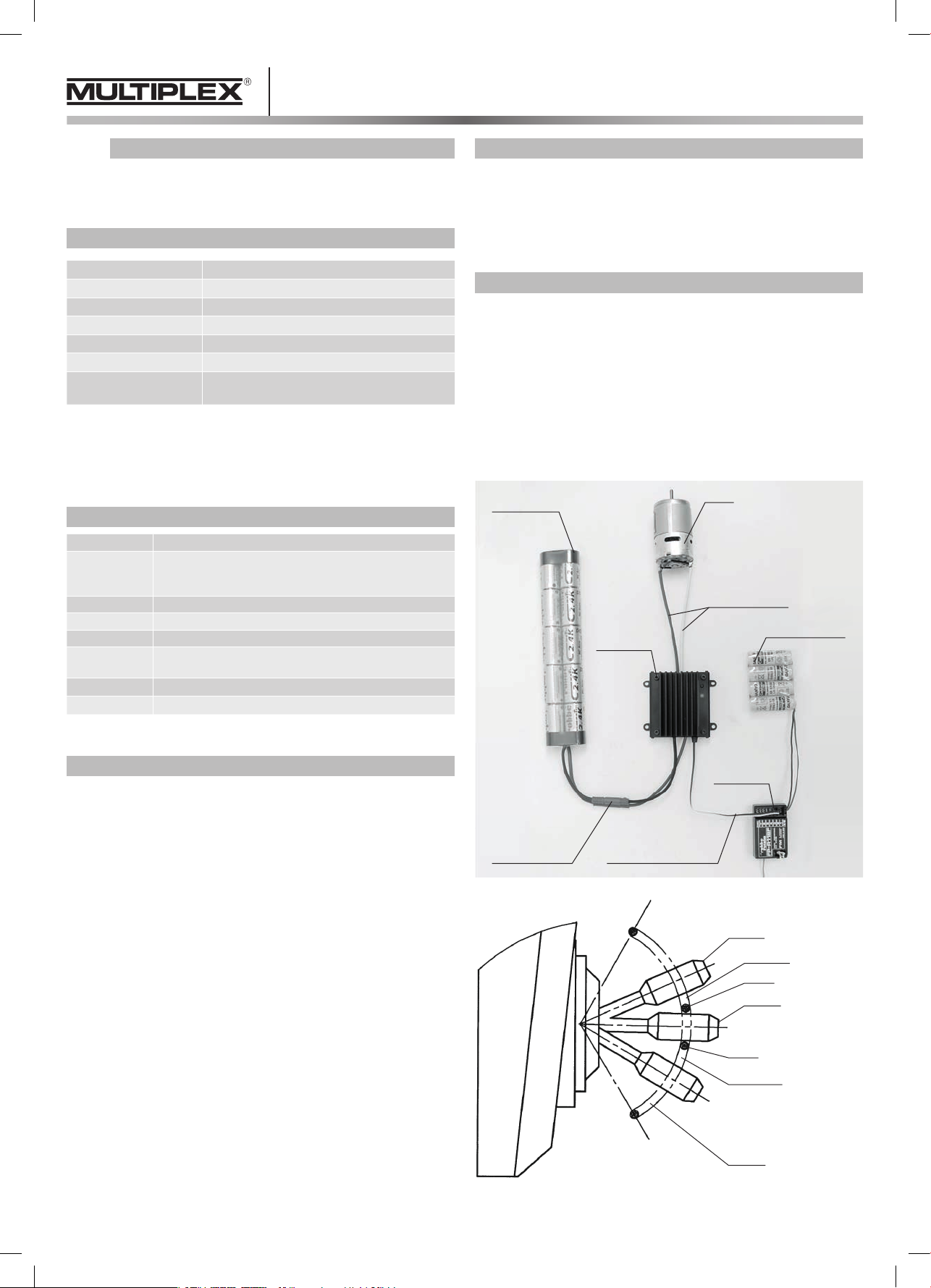
Antriebsakku
Fahrtregler
Motor
Motoranschluss
Empfängerakku
• Besonders feinfühliges, quasi stufenloses Regelverhalten.
Anschluss, Programmierung und Inbetriebnahme
1. Die blau/weissen Motoranschlusskabel sind an die Motoranschlüsse
anzulöten.
2. Für die folgenden Schritte ist unbedingt sicherzustellen, dass sich der
Motor und eventuell montierte Schrauben ungehindert drehen und
niemanden verletzen können.
3. Empfängerkabel des Fahrtreglers mit dem Gaskanal des Empfängers
verbinden.
4. Fernsteuersender einschalten.
5. Empfangsanlage einschalten, Gasknüppel nicht bewegen.
6. Antriebsakku anschließen.
7. Taster ca. 2 Sekunden gedrückt halten. Nach dem loslassen des
Tasters blinkt die LED einmal im Sekundentakt.
8. Gasknüppel in VOLLGAS-VORWÄRTS-Position bringen und Taster zum
Programmieren der VOLLGAS-VORWÄRTS-Position kurz betätigen, die
LED blinkt zweimal im Sekundentakt.
9. Gasknüppel in NEUTRAL-Position bringen und Taster zum Programmieren der NEUTRAL-Position kurz betätigen, die LED blinkt dreimal im
Sekundentakt.
10. Gasknüppel in VOLLGAS-RÜCKWÄRTS-Position bringen und Taster
zum Programmieren der VOLLGASRÜCKWÄRTS-Position kurz betätigen.
• Die Programmierung ist beendet. Wird jetzt der Gasknüppel durch den
VORWÄRTS-Bereich bewegt, muss die Motordrehzahl entsprechend folgen. Dies wird durch gleichmäßiges Leuchten der LED mit zur Drehzahl
proportionaler Intensität angezeigt. Befindet sich der Steuerknüppel im
STOPP-Bereich ist die LED aus.
• Be ndet sich der Gasknüppel im RÜCKWÄRTS-Bereich blinkt die LED im
2 Sekundentakt.
Empfänger
Akkuanschluss Empfängeranschluss
Vollgas
Vorwärts
Stopp
Neutral
Stopp
Rückwärts
Vollgas
Page 2
ROXXY Navy Control 700 – Operating instructions # 31 8616
High-performance speed controller with forward/stop/reverse functions and
easy programming. Suitable for 600- to 700-size motors, Pro, Sports and
Ultra motors or multi-motor models with 400- to 600-size motors.
ROXXY Navy Control 700
Specifi cation
Controller type
Drive battery
Motor current
Pulse frequency
Dimensions
Weight
Connector system
• The term „Motor current“ means the average continuous current at „full throttle
forward“, which flows for the duration of one battery charge (2000 mAh).
• The actual current varies according to the model and the individual operator’s
driving style. The controller can tolerate brief current peaks above this value
without problem.
Forward/stop/reverse
6-18 NC/NiMH, 6-24 V lead-acid
40 A
1 kHz
75 x 67 x 39 mm
231 g
Battery: direct
Motor: direct
Special features
FET
OPTO
POR
TP
PCO
RXF
LED
WP
POWER MOS eld effect transistors (FETs)
Galvanic separation of receiver power circuit and motor
power circuit, to eliminate receiver interference caused by
the electric motor.
Power On Reset – prevents the motor starting when the
battery is connected.
Thermal overload protection
Low voltage shut-off
RX lter – controller shuts down if transmitter signal fails
or suffers interference.
Display of operating and programming functions
Splashproof construction
Fault fi nding
• If it proves impossible to program the controller as described above,
repeat steps 4 to 10 using slightly different stick positions.
• If the motor spins in the wrong direction, i.e. the model moves backwards
when you advance the throttle, swap over the power leads at the motor
terminals.
The speed controller in use
The controller features a range of protective functions, and in everyday operations the unit may shut the motor down for a variety of reasons. You should
be aware of the possible causes:
• The speed controller will shut off the motor (brake active) if it overheats
(e.g. if the motors are too powerful, are run constantly at part-load, or if
cooling is inadequate), if battery voltage falls below a certain level, or if
the transmitter signal fails or suffers interference. The controller can be
re-activated by moving it to the STOP range and then forward again, but
only after you have removed the cause of the shut-off.
• If the controller is in the „OFF“ state as described above, the LED fl ashes
at two-second intervals.
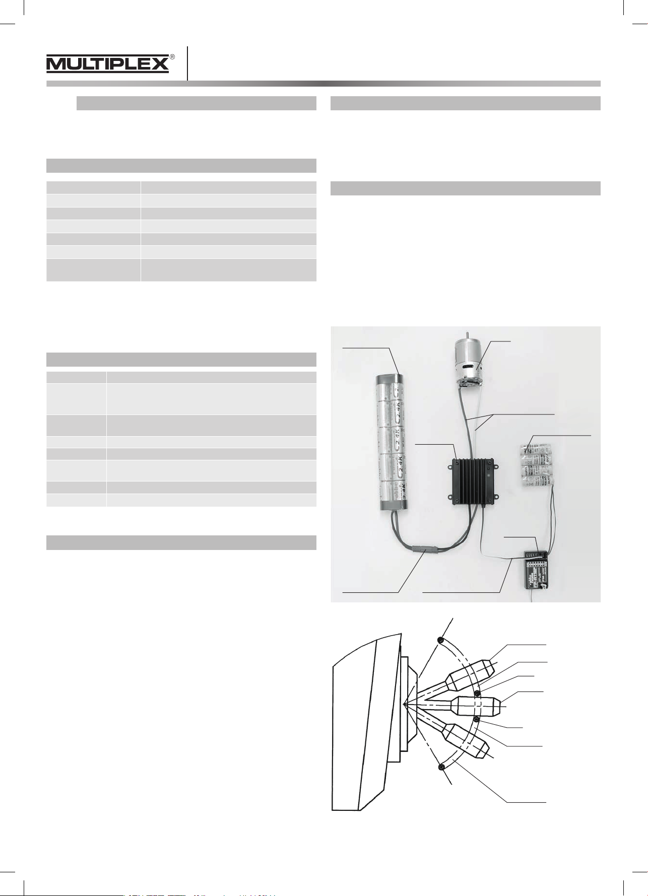
Drive battery
Motor
controller
Motor
Motor connection
Receiver battery
• Ultra-fine, super-smooth control characteristics.
Connecting, programming and using the controller
1. Solder the blue/white power leads to the motor terminals.
2. Before you carry out the following procedure it is absolutely essential to
ensure that the motor (and any propeller mounted on it) is free to spin
without causing damage or injury.
3. Locate the receiver lead attached to the speed controller and connect it
to the receiver throttle channel socket.
4. Switch on the radio control system transmitter.
5. Switch on the receiving system. Do not move the throttle stick.
6. Connect the drive battery.
7. Hold the button pressed in for about 2 seconds. When you release the
button, the LED will fl ash once.
Move the throttle stick to the FULL THROTTLE FORWARD position; press
8.
the button once briefl y to program the FULL THROTTLE FORWARD
position. The LED will fl ash twice with a one-second interval.
9. Move the throttle stick to the NEUTRAL position; press the button once
briefl y to program the NEUTRAL position. The LED will fl ash three
times at one-second intervals.
10.
Move the throttle stick to the FULL THROTTLE REVERSE position; press
the button once briefl y to program the FULL THROTTLE REVERSE
position.
• This completes the programming procedure. If you now move the throttle
stick forward through the FORWARD range, motor speed should rise proportionally. At the same time the LED should glow, its intensity increasing
as speed rises. At the STOP position of the stick the LED is off.
• When you move the throttle stick to the REVERSE range the LED will fl ash
at intervals of 2 seconds.
Battery
connection Receiver connection
Receiver
Full throttle
Forward
Stop
Neutral
Stop
Backward
Full throttle
Page 3
ROXXY Navy Control 700 – Notice d’utilisation # 31 8616
Variateur puissant à faible encombrement disposant des fonctions marche
avant, arrêt et marche arrière et d’une programmation simple pour un mon-
tage sur les moteurs de type 600 à 700 ou les moteurs Pro, Sport et Ultra
ou une exploitation combinée de plusieurs moteurs (des séries 400 à 600).
ROXXY Navy Control 700
Caractéristiques techniques
Fonctions
Accu d’entraînement
Courant du moteur
Fréquence d’impulsion
Encombrement
Poids
Système de connexion
•
Par courant moteur on entend le courant permanent moyen à « plein régime
marche avant » qui est fourni pour la durée de la charge de l’accu (2000 mAh).
• Le courants effectifs dépendent du modèle et des habitudes d’asservisse-
ment individuelles. Brièvement des pics de courant plus élevés ne posent
pas de problèmes.
marche avant – arrêt – arrière
6 à 18 éléments Cd-Ni/NiMH ou 6 à
24 volts accu au plomb
40 A
1 kHz
75 x 67 x 39 mm
231 g
connexion directe de l’accu,
connexion directe du moteur
Particularités
Origine possible des anomalies
• Lorsqu’il ne s’avère pas possible de programmer le variateur comme
décrit ci-dessus, reprendre les étapes de programmation de 4 à 10 en
modi ant légèrement la position du manche.
• S’il s’avère indispensable d’inverser le sens de rotation du moteur a n
que la marche avant du manche corresponde effectivement à la marche
avant du moteur.
Le variateur en marche
Pour la mise en oeuvre pratique du variateur, il faut connaître les relations
décrites ci-dessous :
• Le variateur est équipé de diverses fonctions de protection. En présence
d’une température excessive, par exemple avec des moteurs trop puissants,
en charge permanente ou en charge partielle ou en présence d’un
refroidissement insuf sant, lorsque la tension de l’accu est insuf sante
ou lorsque le signal de l’émetteur est absent ou défectueux, le variateur
commute automatiquement sur freinage en coupant le moteur. Dès que
l’origine de la perturbation est supprimée, le fait de redonner des gaz
permet de quitter la zone d’ARRET et de réactiver le variateur.
• L’état « ARRET » est signalé par le clignotement de la LED au rythme de
deux secondes.
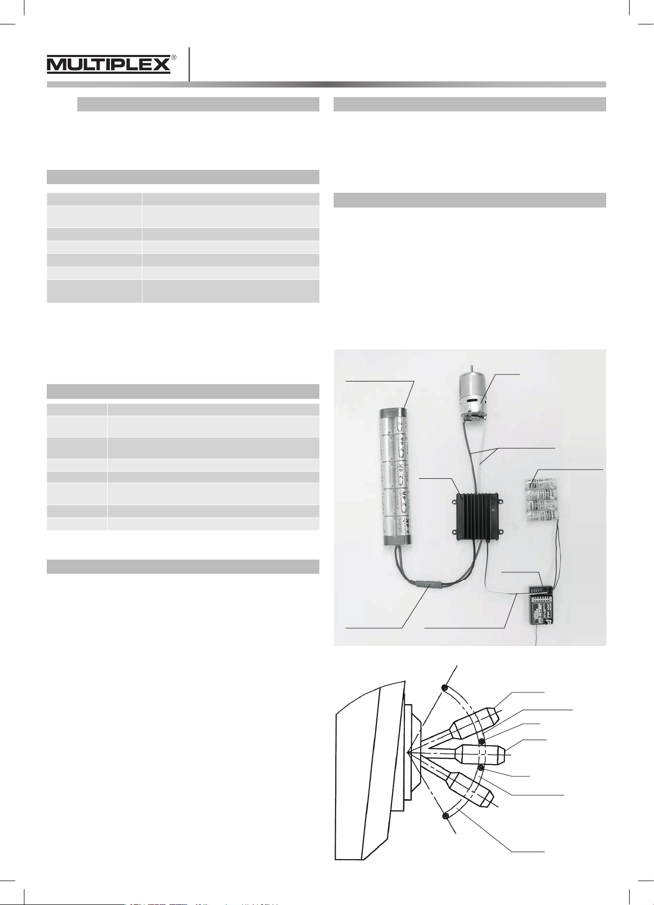
Accu de propulsion
Moteur
FET
OPTO
POR
TP
PCO
RXF
LED
WP
• Comportement pratiquement sans étages et très précis de la régulation.
transistors à effet de champ POWER-MOS
séparation galvanique des circuits de réception et du moteur
pour éviter les pannes de réception dues au moteur
protection au démarrage empêchant le démarrage inopiné
du moteur
protection contre les températures excessives
commutation de sous-tension
ltre RX, arrêt du variateur en l’absence de signal de
l’émetteur ou lorsque le signal de l’émetteur est défectueux
af chage des fonctions de service et de programmation
protection contre les projections d’eau
Branchement, programmation et mise en service
1. Raccorder les brins bleu/blanc du cordon de connexion du moteur aux
contacts du moteur.
2. Pour les étapes suivantes il faut s’assurer absolument que le moteur et
l’hélice éventuellement déjà en place ne tournent pas et ne soient pas
susceptibles de présenter un danger.
3. Raccorder vers le cordon du récepteur du variateur à la voie des gaz du
récepteur.
4. Mettre l’ensemble de radiocommande en marche.
5. Mettre le récepteur en marche sans déplacer le manche des gaz.
6. Raccorder l’accu du récepteur
7. Maintenir la touche enfoncée approx. 2 secondes. Lorsque la touche
est relâchée, la LED clignote au rythme de la seconde.
8. Amener le manche des gaz en position PLEIN RÉGIME MARCHE
AVANT, actionner brièvement la touche pour la programmation de la
position PLEIN RÉGIME MARCHE AVANT. La LED clignote deux fois
au rythme de la seconde.
9. Amener le manche des gaz en position NEUTRE, actionner brièvement
la touche pour la programmation de la position NEUTRE. La LED clignote
trois fois au rythme de la seconde.
10. Amener le manche des gaz en position PLEIN RÉGIME MARCHE
ARRIERE, actionner brièvement la touche pour la programmation de la
position PLEIN RÉGIME MARCHE ARRIÈRE.
• La programmation est terminée. Maintenant lorsque le manche est poussé
dans le secteur de la MARCHE AVANT, le moteur suit la progression. Cet
état est signalé par la luminosité proportionnelle de la LED. Lorsque le
manche se trouve en position ARRET, la LED est éteinte.
• Lorsque le manche des gaz se trouve en position MARCHE ARRIÈRE, la
LED clignote au rythme de 2 secondes.
Variateur
Raccord accu Raccord du récepteur
Raccord moteur
Alim. du récepteur
Récepteur
Plein gaz
Marche avant
Arrêt
Neutre
Arrêt
Marche arrière
Plein gaz
Page 4
Sicherheitshinweise
!
• Beachten Sie die technischen Daten des Reglers.
• Polung aller Anschlusskabel beachten.
• Kurzschlüsse unbedingt vermeiden.
• Den Regler so einbauen bzw. verpacken, dass er nicht mit Fett,
Öl oder Wasser in Berührung kommen kann.
• Für ausreichende Luftzirkulation sorgen.
• Antriebsmotor wirkungsvoll entstören.
• Der Regler ist nur spritzwassergeschützt. Einwirkung von Feuchtigkeit
ist zu vermeiden.
Consignes de sécurité
!
• Tenir compte des caractéristiques techniques du variateur.
• Respecter la polarité de tous les câbles de raccordement.
• É viter absolument les courts-circuits.
• Installer ou emballer le variateur de telle sorte qu’il ne puisse entrer
en contact avec de la graisse, de l’huile ou de l’eau.
• Etablir une circulation d’air sufsante.
• Antiparasiter efcacement le moteur.
• La variateur est certes protégé contre les projections d’eau
mais il faut éviter l’humidité.
Entsorgung
Dieses Symbol bedeutet, dass elektrische und elektronische
Geräte am Ende ihrer Nutzungsdauer vom Hausmüll getrennt,
entsorgt werden müssen. Entsorgen Sie das Gerät bei Ihrer örtlichen, kommunalen Sammelstelle oder Recycling-Zentrum. Dies
gilt für alle Länder der Europäischen Union sowie in anderen Eu-
ropäischen Ländern mit separatem Sammelsystem.
CE-Konformitätserklärung
Die Bewertung des Gerätes erfolgte nach europäisch harmonisierten
nien. Sie besitzen daher ein Produkt, das hinsichtlich der Konstruktion die
Schutzziele der Europäischen Gemeinschaft zum sicheren Betrieb der Geräte erfüllt. Die Konformitätserklärung des Gerätes kann bei der MULTIPLEX
Modellsport GmbH & Co.KG angefordert werden.
Irrtum und technische Änderungen vorbehalten
Copyright Multiplex Modellsport 2015
Kopie und Nachdruck, auch auszugsweise, nur mit schriftlicher Genehmigung der Multiplex Modellsport GmbH & Co.KG
Multiplex Modellsport GmbH & Co. KG
Westliche Gewerbestr. 1
75015 Bretten · Germany
Multiplex Service: +49 (0) 7252 - 5 80 93 33
www.multiplex-rc.de
Safety notes
!
• Keep within the limits stated in the speed controller specication.
• Maintain correct polarity of all connecting leads.
• Take great care to avoid short-circuits.
• Install and protect the speed controller in such a way that it cannot
come into contact with grease, oil or water.
• Ensure that air circulation is adequate.
• Fit effective suppression measures to the electric motor.
• The controller is only splashproof. As far as possible keep it
well away from water.
Richtli-
À noter
• Après avoir quitté la marche avant, la marche arrière est utilisée
d’abord brièvement pour effectuer un freinage proportionnel.
• Perturbations dans la transmission, sous-tension et surchauffe
provoquent la coupure du moteur. Le fait de changer la position
du manche des gaz (marche arrière – marche avant) permet de
remettre le moteur en marche.
Mise au rebut
Ce symbole signie que les appareils électriques et électroniques
irréparables ou en n de cycle d’exploitation doivent être mis au
rebut non pas avec les ordures ménagères mais dans les déchet-
teries spécialisées. Portez-les dans les collecteurs communaux
appropriés ou un centre de recyclage spécialisé. Cette remarque
pays européens pourvus d’un système de collecte spécique.
s’applique aux pays de la Communauté européenne et aux autres
Déclaration de conformité CE
Le produit cité ci-dessus est conforme par rapport aux impératifs des di-
rectives harmonisées de l’union euro-péenne. De ce fait vous possédez un
produit qui, de par sa construction, respecte la restriction de sécurités en
vigueurs au niveau de l’union européenne concernant l’utilisation sécurisée
des appa-reils électroniques. Vous pouvez demander la déclaration de conformité de votre modèle auprès de la société MULTIPLEX Modellsport GmbH
& Co.KG.
Sous réserve d‘erreur d‘impression et de modification technique
Copyright Multiplex Modellsport 2015
La copie et la reproduction, même partielles, sont soumises à l‘autorisation écrite
de la Sté Multiplex Modellsport GmbH & Co.KG
Multiplex Modellsport GmbH & Co. KG
Westliche Gewerbestr. 1
75015 Bretten
Germany
Multiplex Service: +49 (0) 7252 - 5 80 93 33
www.multiplex-rc.de
Disposal
This symbol means that it is essential to dispose of electrical and electronic
equipment separately from the domestic refuse when it reaches
the end of its useful life. Take your unwanted equipment to your
local communal collection point or recycling centre. This applies
to all countries of the European Union, and to other European
countries with separate waste collection systems.
CE Conformity Declaration
This device has been assessed and approved in accordance with European
harmonised directives. This means that you possess a product whose design
and construction full the protective aims of the European Community designed to ensure the safe operation of equipment. If required, you can request
MULTIPLEX Modellsport
formity Declaration.
the foot of the page.
Errors and omissions excepted.
Technical modifications reserved.
Copyright Multiplex Modellsport 2015
Duplication and copying of the text, in whole or in part, is only
with the prior written approval of Multiplex Modellsport
Multiplex Modellsport GmbH & Co. KG
Westliche Gewerbestr. 1
75015 Bretten · Germany
Multiplex Service: +49 (0) 7252 - 5 80 93 33
www.multiplex-rc.de
GmbH & Co.KG to supply a copy of the unit’s Con-
Please contact the company using the contact details at
permitted
GmbH & Co.KG
 Loading...